

Page 1

DX-1S DIGITAL PABX
Installation Manual
Version 6 - Draft 01
Revised
on
18 August, 1999
CONNECTION ELECTRONICS LTD.
Page 2
DX-1S DIGITAL PABX - Installation Manual
NOTICE
The information contained in this document is believed to accurate in all respects but is not
warranted by Connection Electronics Limited. The information is subject to change without notice
and should not be construed in any way as a commitment by Connection Electronics Limited or its
affiliates and subsidiaries assume no responsibility for any errors or omissions in this document.
Revisions of this document or new editions of it may be issued to incorporate such changes.
ii
Page 3

DX-1S DIGITAL PABX - Installation Manual
TABLE OF CONTENTS
1.INTRODUCTION........................................................................................................................................1
2.INSTALLATION SITE REQUIREMENTS..................................................................................................1
2.1ENVIRONMENT REQUIREMENTS.........................................................................................................1
2.2SPACE REQUIREMENTS.......................................................................................................................1
2.3LOCATION REQUIREMENTS.................................................................................................................2
2.4AC POWER REQUIREMENTS FOR AC/DC POWER SUPPLY.............................................................2
2.5GROUNDING REQUIREMENTS.............................................................................................................2
2.6REQUIREMENTS OF AC POWER FOR MFC-1S CONSOLE................................................................3
3.CABLING...................................................................................................................................................1
3.1GENERAL PRECAUTIONS.....................................................................................................................1
3.2MAXIMUM LENGTH OF EXTENSION CABLE & DOOR PHONE CABLE..............................................1
3.3MAXIMUM LENGTH OF CONSOLE CABLE...........................................................................................1
4.HARDWARE OVERVIEW..........................................................................................................................1
4.1SYSTEM HARDWARE ASSEMBLY CODE.............................................................................................1
4.2HARDWARE CONFIGURATION.............................................................................................................1
4.3DX-1S MODULE MOTHER BOARD........................................................................................................2
4.4DX-1S MODULE ACCESSORIES............................................................................................................2
4.5DX-1S CABINET......................................................................................................................................3
4.6DX-1S MODULE SYSTEM CABINET......................................................................................................4
4.7DX-1S MODULE CONTROL CARD (MCC).............................................................................................5
4.8DX-1S POWER SUPPLY CARD (PSC)...................................................................................................6
4.9DX-1S TRK/EXT CARD - 4 TRK + 12 EXT (T/E).....................................................................................7
4.10DX-1S EXT CARD - 16 EXT (EXT)........................................................................................................8
4.11DX-1S CALLER ID CARD (CIC)............................................................................................................9
4.12SPS-4820 BATTERY BACKUP POWER SUPPLY..............................................................................10
4.13CAD600A BATTERY BACKUP POWER SUPPLY..............................................................................14
4.14MFC-1S PC INTERFACE CARD WITH CONSOLE SOFTWARE...................................................... 17
4.15MFC-1S CONSOLE..............................................................................................................................18
4.16DX-1S DISA VOICE CARD..................................................................................................................19
4.17DX-1S POWER FAILURE TRANSFER MODULE...............................................................................19
5.HARDWARE INSTALLATION...................................................................................................................1
5.1BASIC PRECAUTIONS FOR INSTALLATION........................................................................................1
5.2PREPARE BASIC INSTALLATION..........................................................................................................1
5.3SYSTEM GROUND TERMINAL...............................................................................................................3
5.4BACKUP BATTERIES INSTALLATION...................................................................................................3
5.5MODULE SYSTEM CABINET INSPECTION...........................................................................................3
5.6MOTHER BOARD DIP SWITCH SETTING.............................................................................................3
5.7SPS-4820 POWER SUPPLY INSPECTION............................................................................................4
5.8CONNECTION BETWEEN SYSTEM CABINET AND SPS-4820 POWER SUPPLY..............................4
5.9VERIFY GROUND CONNECTION..........................................................................................................6
5.10CONNECTORS IN REAR PANEL OF MODULE SYSTEM CABINET..................................................7
5.11CONNECT CONSOLE CABLE FOR MODULE SYSTEM CABINET.....................................................8
5.12CONNECT MUSIC/PAGE/RELAY CABLE FOR MODULE SYSTEM CABINET...................................9
5.13CONNECT LINE CONNECTOR CABLES FOR MODULE SYSTEM CABINET................................. 10
5.14INSTALL POWER FAILURE TRANSFER MODULE...........................................................................26
5.15INSTALL POWER SUPPLY CARD......................................................................................................30
5.16INSTALL MODULE CONTROL CARD.................................................................................................30
5.17INSTALL DISA VOICE CARD..............................................................................................................30
5.18INSTALL TRK/EXT CARD AND EXT CARD.......................................................................................32
5.19INSTALL CALLER ID CARD................................................................................................................32
5.20INSTALL MFC-1S PC INTERFACE CARD..........................................................................................34
5.21INSTALL MFC-1S CONSOLE..............................................................................................................35
5.22PRINTER CONNECTION....................................................................................................................41
5.23EXTERNAL MUSIC SOURCE IMPEDANCE REQUIREMENT...........................................................41
5.24PAGING SYSTEM OUTPUT IMPEDANCE REQUIREMENT..............................................................41
5.25DOOR LOCK CONNECTION REQUIREMENT...................................................................................42
6.BASIC HARDWARE TEST........................................................................................................................1
6.1CHECKING...............................................................................................................................................1
6.2POWER ON TEST...................................................................................................................................1
iii
Page 4

DX-1S DIGITAL PABX - Installation Manual
6.3MFC-1S CONSOLE POWER ON TEST..................................................................................................2
6.4POWER FAILURE TRANSFER MODULE TEST....................................................................................2
6.5EXTENSION FUNCTIONAL TEST..........................................................................................................2
6.6TRUNK LINE FUNCTIONAL TEST..........................................................................................................2
6.7CALLER ID CARD FUNCTION TEST......................................................................................................3
6.8EXTERNAL MUSIC PORT FUNCTIONAL TEST....................................................................................3
6.9PAGING PORT FUNCTIONAL TEST......................................................................................................3
6.10DOOR PHONE FUNCTIONAL TEST....................................................................................................3
6.11DOOR LOCK FUNCTIONAL TEST.......................................................................................................3
7.UPGRADE SYSTEM SOFTWARE............................................................................................................1
7.1DESCRIPTION.........................................................................................................................................1
7.2BACKUP PROGRAMMING DATA...........................................................................................................1
7.3INTEGRATED CIRCUITS FOR UPGRADE.............................................................................................1
7.4BASIC PRECAUTIONS FOR UPGRADE................................................................................................2
7.5REWRITE I.C. U2 FOR SOFTWARE UPGRADE...................................................................................2
7.6REPLACE I.C. U37 FOR SOFTWARE UPGRADE.................................................................................2
7.7REWRITE I.C. U79 FOR SOFTWARE UPGRADE.................................................................................2
7.8POWER ON TEST...................................................................................................................................2
8.DX-1SU.......................................................................................................................................................1
8.1DESCRIPTION.........................................................................................................................................1
8.2DX-1SU MODULE SYSTEM CABINET...................................................................................................1
8.3DX-1SU POWER SUPPLY......................................................................................................................1
8.4INSTALLATION........................................................................................................................................2
LIST OF FIGURES
FIGURE 2-2.1 TOP AND SIDE PANEL CLEARANCE REQUIREMENT.....................................................1
FIGURE 2-2.2 FRONT AND REAR PANEL CLEARANCE REQUIREMENT..............................................2
FIGURE 4-4.1 DX-1S CABINET PHYSICAL DIMENSION..........................................................................3
FIGURE 4-4.2 DX-1S MODULE SYSTEM CABINET FRONT VIEW...........................................................4
FIGURE 4-4.3 SPS-4820 POWER SUPPLY FRONT PANEL....................................................................11
FIGURE 4-4.4 CAD600A POWER SUPPLY FRONT PANEL....................................................................14
FIGURE 4-4.5 MFC-1S PC INTERFACE CARD........................................................................................17
FIGURE 4-4.6 DX-1S POWER FAILURE TRANSFER MODULE CIRCUIT DIAGRAM............................20
FIGURE 5-5.1 HARDWARE PLACEMENT SUGGESTION (WITH SPS-4820 POWER SUPPLY)............ 2
FIGURE 5-5.2 HARDWARE PLACEMENT SUGGESTION (WITH SPS-4820A POWER SUPPLY)..........3
FIGURE 5-5.3 MODULE SYSTEM CABINET & POWER SUPPLY CONNECTION DIAGRAM.................5
FIGURE 5-5.4 VERIFY GROUND CONNECTION DIAGRAM.....................................................................6
FIGURE 5-5.5 DX-1S MODULE SYSTEM CABINET REAR PANEL VIEW................................................8
FIGURE 5-5.6 CONSOLE CONNECTOR DIAGRAM..................................................................................9
FIGURE 5-5.7 MUSIC/PAGE/RELAY CONNECTOR DIAGRAM................................................................9
FIGURE 5-5.8 LINE CONNECTOR DIAGRAM..........................................................................................10
FIGURE 5-5.9 DX-1S POWER FAILURE TRANSFER MODULE PANEL................................................26
FIGURE 5-5.10 POWER FAILURE TRANSFER MODULE INSTALLATION............................................27
iv
Page 5

DX-1S DIGITAL PABX - Installation Manual
FIGURE 5-5.11 PFT LINE CONNECTOR DIAGRAM................................................................................28
FIGURE 5-5.12 DISA VOICE CARD INSTALLATION...............................................................................31
FIGURE 5-5.13 CIC CHANNEL CONNECT TO C.O. LINE IN PARALLEL WITH TRUNK PORT........... 32
FIGURE 5-5.14 REAR PANEL OF MFC-1S CONSOLE (VERSION A).....................................................36
FIGURE 5-5.15 REAR PANEL OF MFC-1S CONSOLE (VERSION B).....................................................36
FIGURE 5-5.16 CONSOLE-IN AND CONSOLE-OUT (MJ-66) CONNECTOR DIAGRAM.......................37
FIGURE 5-5.17 MFC-1S CONSOLES CONNECTION DIAGRAM............................................................39
FIGURE 5-5.18 CONSOLE LOOP TESTING PLUG DIAGRAM................................................................40
FIGURE 5-5.19 DC DOOR LOCK CONNECTION.....................................................................................42
FIGURE 5-5.20 AC DOOR LOCK CONNECTION.....................................................................................42
FIGURE 7-7.1 MODULE CONTROL CARD LAYOUT.................................................................................1
FIGURE 8-8.1 DX-1SU SYSTEM CABINET, POWER & BATTERY CONNECTION DIAGRAM................3
LIST OF TABLES
TABLE 2-1 ENVIRONMENT REQUIREMENTS..........................................................................................1
TABLE 3-1 MAXIMUM LENGTH OF EXTENSION CABLE........................................................................1
TABLE 3-2 MAXIMUM LENGTH OF CONSOLE CABLE...........................................................................1
TABLE 4-1 SYSTEM HARDWARE ASSEMBLY CODE..............................................................................1
TABLE 4-2 HARDWARE CONFIGURATION...............................................................................................1
TABLE 4-3 DX-1S MODULE MOTHER BOARD ASSEMBLY....................................................................2
TABLE 4-4 MODULE MOTHER BOARD DIP SWITCH SETTING..............................................................2
TABLE 4-5 DX-1S CABINET ASSEMBLY...................................................................................................3
TABLE 4-6 DX-1S MODULE SYSTEM CABINET ASSEMBLY..................................................................4
TABLE 4-7 MODULE SYSTEM CABINET CARD SLOTS..........................................................................4
TABLE 4-8 DX-1S MODULE CONTROL CARD ASSEMBLY.....................................................................5
TABLE 4-9 LED INDICATION IN MODULE CONTROL CARD..................................................................5
TABLE 4-10 DX-1S POWER SUPPLY CARD ASSEMBLY........................................................................6
TABLE 4-11 POWER SUPPLY CARD FUSES VALUE...............................................................................6
TABLE 4-12 DX-1S TRK/EXT CARD ASSEMBLY......................................................................................7
TABLE 4-13 INDICATION OF TRUNK LED IN TRK/EXT CARD................................................................7
TABLE 4-14 INDICATION OF EXTENSION LED IN TRK/EXT CARD........................................................7
TABLE 4-15 DX-1S EXT CARD ASSEMBLY..............................................................................................8
v
Page 6

DX-1S DIGITAL PABX - Installation Manual
TABLE 4-16 LED INDICATION IN EXT CARD............................................................................................8
TABLE 4-17 DX-1S CALLER ID CARD ASSEMBLY..................................................................................9
TABLE 4-18 LED INDICATION IN CALLER ID CARD................................................................................9
TABLE 4-19 SPS-4820 BATTERY BACKUP POWER SUPPLY ASSEMBLY.........................................10
TABLE 4-20 SPS-4820 POWER SUPPLY SPECIFICATION....................................................................13
TABLE 4-21 BACKUP TIME AGAINST BATTERY CAPACITY................................................................13
TABLE 4-22 CAD600A BATTERY BACKUP POWER SUPPLY ASSEMBLY..........................................14
TABLE 4-23 CAD600A POWER SUPPLY SPECIFICATION....................................................................16
TABLE 4-24 BACKUP TIME AGAINST BATTERY CAPACITY................................................................16
TABLE 4-25 MFC-1S PC INTERFACE CARD ASSEMBLY......................................................................17
TABLE 4-26 MFC-1S CONSOLE ASSEMBLY..........................................................................................18
TABLE 4-27 DX-1S DISA VOICE CARD ASSEMBLY...............................................................................19
TABLE 4-28 DX-1S POWER FAILURE TRANSFER MODULE ASSEMBLY...........................................19
TABLE 5-1 SPS-4820 POWER OUTPUT TERMINAL.................................................................................4
TABLE 5-2 MODULE SYSTEM CABINET POWER INPUT TERMINAL....................................................4
TABLE 5-3 MODULE SYSTEM CABINET REAR PANEL CONNECTORS...............................................7
TABLE 5-4 CONSOLE CONNECTOR PIN ASSIGNMENT.........................................................................8
TABLE 5-5 M/P/R CONNECTOR PIN ASSIGNMENT.................................................................................9
TABLE 5-6 LINE CONNECTOR L01 PIN ASSIGNMENT.........................................................................11
TABLE 5-7 LINE CONNECTOR L02 PIN ASSIGNMENT.........................................................................12
TABLE 5-8 LINE CONNECTOR L03 PIN ASSIGNMENT.........................................................................13
TABLE 5-9 LINE CONNECTOR L04 PIN ASSIGNMENT.........................................................................14
TABLE 5-10 LINE CONNECTOR L05 PIN ASSIGNMENT.......................................................................15
TABLE 5-11 LINE CONNECTOR L06 PIN ASSIGNMENT.......................................................................16
TABLE 5-12 LINE CONNECTOR L07 PIN ASSIGNMENT.......................................................................17
TABLE 5-13 LINE CONNECTOR L08 PIN ASSIGNMENT.......................................................................18
TABLE 5-14 LINE CONNECTOR L09 PIN ASSIGNMENT.......................................................................19
TABLE 5-15 LINE CONNECTOR L10 PIN ASSIGNMENT.......................................................................20
TABLE 5-16 LINE CONNECTOR L11 PIN ASSIGNMENT.......................................................................21
TABLE 5-17 LINE CONNECTOR L12 PIN ASSIGNMENT.......................................................................22
TABLE 5-18 LINE CONNECTOR L13 PIN ASSIGNMENT.......................................................................23
TABLE 5-19 LINE CONNECTOR L14 PIN ASSIGNMENT.......................................................................24
vi
Page 7

DX-1S DIGITAL PABX - Installation Manual
TABLE 5-20 LINE CONNECTOR L15 PIN ASSIGNMENT.......................................................................25
TABLE 5-21 POWER FAILURE TRANSFER MODULE PANEL CONNECTORS...................................26
TABLE 5-22 PFT LINE CONNECTOR PIN ASSIGNMENT.......................................................................29
TABLE 5-23 LINE CONNECTOR PIN ASSIGNMENT OF CALLER ID CARD.........................................33
TABLE 5-24 PC STATION REQUIREMENTS FOR MFC-1S CONSOLE.................................................34
TABLE 5-25 MFC-1S CONSOLE CONNECTORS....................................................................................35
TABLE 5-26 MODULE SYSTEM CABINET TO 1ST MFC-1S CONSOLE CONNECTION......................37
TABLE 5-27 MFC-1S CONSOLE TO CONSOLE CONNECTION.............................................................38
TABLE 5-28 CONSOLE LOOP TESTING PLUG PIN ASSIGNMENT......................................................40
TABLE 5-29 SERIAL PRINTER PORT SPECIFICATION......................................................................... 41
TABLE 5-30 COM 1 CONNECTOR PIN ASSIGNMENT...........................................................................41
TABLE 5-31 DOOR LOCK RELAY CONTACT.........................................................................................42
TABLE 7-1 INTEGRATED CIRCUIT FOR UPGRADE.................................................................................1
TABLE 8-2 DX-1SU SYSTEM CABINET POWER OUTPUT TERMINAL...................................................3
vii
Page 8

Page 9

DX-1S DIGITAL PABX - Installation Manual
1.INTRODUCTION
This manual provides general installation procedures for DX-1S Digital PABX System. It is suggested that
the technical persons should read these information thoroughly before beginning the installation. Also
refer to Programming Manual for information about customizing the system for a particular site.
The Installation Manual is divided into the following sections :
Introduction
Installation Site Requirements
Cabling
Hardware Overview
Hardware Installation
Basic Hardware Test
Upgrade System Software
DX-1SU
1
Page 10

Page 11
DX-1S DIGITAL PABX - Installation Manual
2.INSTALLATION SITE REQUIREMENTS
The DX-1S Digital PABX System should be installed in any location which fulfill the following
requirements.
2.1ENVIRONMENT REQUIREMENTS
The temperature and humidity of the operating environment should be within the following range :
Operation Conditions Storage Conditions
Temperature 0°C to 50°C 0°C to 50°C
Relative Humidity 0% to 90% noncondensing 20% to 95% noncondensing
Table 2-1 ENVIRONMENT REQUIREMENTS
2.2SPACE REQUIREMENTS
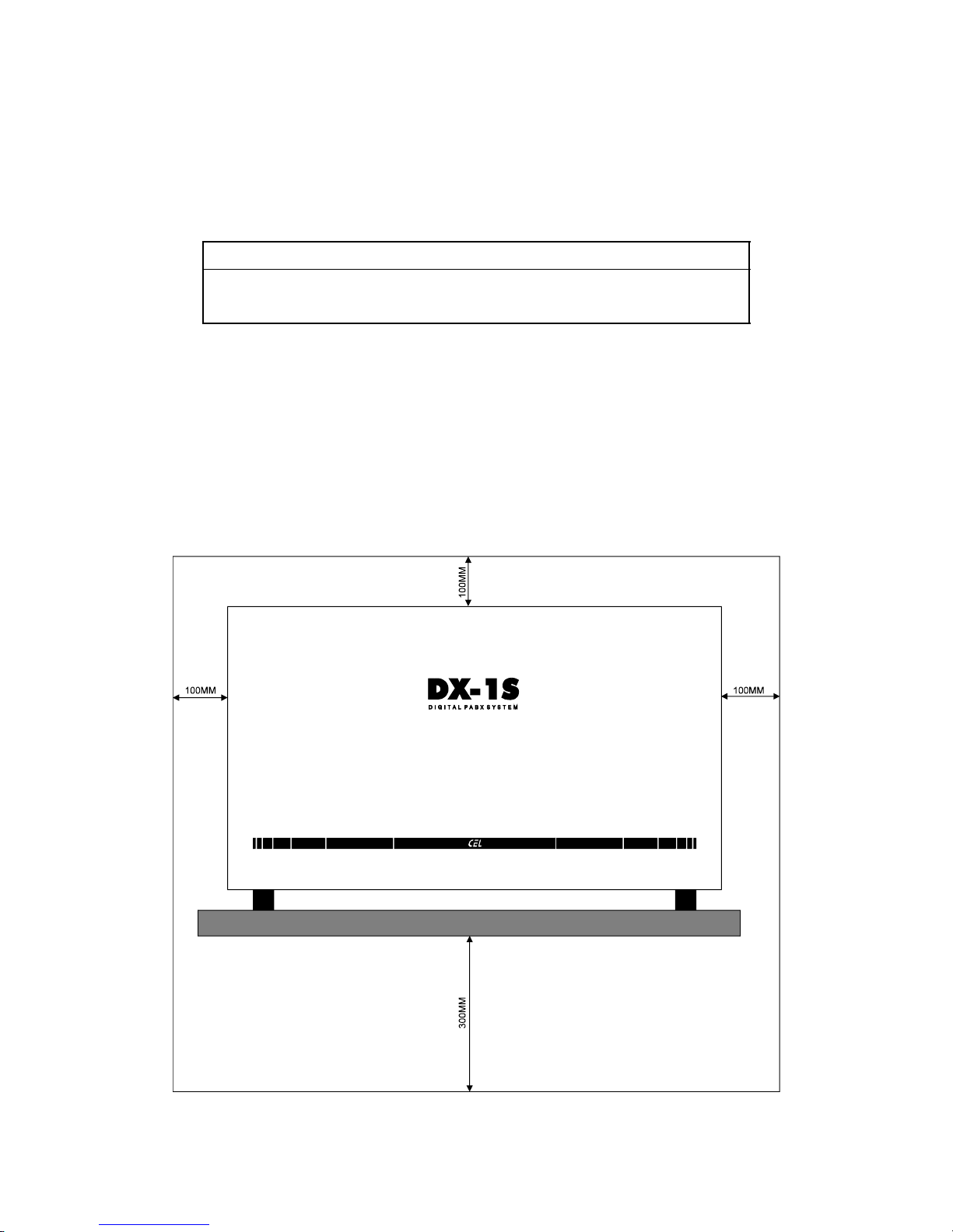
The minimum space between the surrounding surface and left panel, right panel and top panel of DX-1S
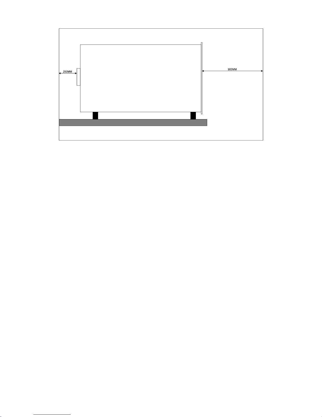
System Cabinet should be greater than 100mm. The minimum space between the rear wall and the back
panel should be greater than 250mm. The clearance is for ventilation and cables installation. It should
leave at least 900mm space in front of the System Cabinet for the technician to install and replace the
cards. It is advised to install the System Cabinet 300mm above the floor to avoid possible flooding. The
Battery Backup Power Supply SPS-4820 and CAD600A have similar space requirement.
Figure 2-2.1 TOP AND SIDE PANEL CLEARANCE REQUIREMENT
1
Page 12
DX-1S DIGITAL PABX - Installation Manual
Figure 2-2.2 FRONT AND REAR PANEL CLEARANCE REQUIREMENT
2.3LOCATION REQUIREMENTS
There are some guide lines for location selection :
Dry, clean and good ventilated.
Easy accessible
Not extreme heat or cold
No direct sunlight
No corrosive fumes or exhaust from machinery
Not near a sprinkler system, sweating pipes, steam pipes or steam vents
Not near a photocopier machine, blueprint equipment
Not in passageways
AC power available
2.4AC POWER REQUIREMENTS FOR AC/DC POWER SUPPLY
The AC/DC Power Supply requires a single phase 220V 50Hz AC main power. The AC power should
meet the following requirements :
The power socket is dedicated for system use and should not share with other equipment.
The power socket should be able to draw 8A current capacity.
The power socket must be a 3-wire type with ground wire connected to the ground of the electrical
system.
The power cord, power socket and plug should meet the electrical safety standard and requirement.
It is advised to install an AC Surge Protector between power supply and AC power.
The AC power regulation should meet the requirement of the AC/DC Power Supply. For SPS-4820
Power Supply, the AC power should be within AC 220V 15 %, 50~60 Hz.
For the region where the AC power is very unstable and fluctuate, it is advised to install the AC
Regulator for the system.
2.5GROUNDING REQUIREMENTS
The System need a low resistance grounding system to bypass surge current. If the system ground is not
well connected or the resistance is too high, the system will be damaged by external surge voltage, such as
lightning, power line surge etc.. The grounding system should include a System Ground Terminal to
concentrate all the hardware ground and connect to an approved building ground (such as cold water pipe
etc.) directly using a #6 AWG insulated green wire. The total resistance must not be over 5 ohms.
2
Page 13

DX-1S DIGITAL PABX - Installation Manual
2.6REQUIREMENTS OF AC POWER FOR MFC-1S CONSOLE
The MFC-1S Console requires a single phase 220V 50Hz AC main power. The AC power should meet the
following requirements :
The power socket is dedicated for system use and should not share with other equipment.
The power socket should be able to draw 2A current capacity.
The power socket must be a 3-wire type with ground wire connected to the ground of the electrical
system.
The power cord, power socket and plug should meet the electrical safety standard and requirement.
It is advised to install an AC Surge Protector between the console and the AC power.
The AC power regulation should be within AC 220V 15 %, 50~60 Hz.
For the region where the AC power is very unstable and fluctuate, it is advised to install the AC
Regulator for the Console.
3
Page 14

Page 15

DX-1S DIGITAL PABX - Installation Manual
3.CABLING
3.1GENERAL PRECAUTIONS
Use Module Distribution Frame (MDF) to concentrate all incoming and outgoing cables.
Must install Gas Arrestor or Surge Protector for all the trunk lines to protect the system from surge
damage.
Must install Gas Arrestor or Surge Protector for extension lines which are installed outside the building.
Must install Gas Arrestor or Surge Protector in all extension lines when the system is installed in the
region where lightning happen very often.
Verify there is no short circuit between the cables and ground. The short circuit may cause the system
to damage or wrong operation.
Verify there is no short circuit between cables after installation. The short circuit may cause the system
to damage or wrong operation.
The ground cables of MDF and Module System Cabinet must be well connected to low resistance
approval building ground, otherwise the protective function of surge protection device will degrade or
malfunction.
Telephone cables run alongside or cross electricity power cables, the minimum separations shown
below should be followed :
a) 460mm from the high voltage (exceeding 650V measured to earth) cables.
b) 102mm from the medium voltage (between 200V and 650V measured to earth) cables.
c) 51mm from the low voltage (under 200V measured to earth) cables.
3.2MAXIMUM LENGTH OF EXTENSION CABLE & DOOR PHONE CABLE
The loop resistance for the extension lines including the telephone resistance should not be over 1200
ohms. The following table indicate a typical condition :
Maximum allow
loop resistance
Telephone
resistance
Conductor
diameter
Cable loop
resistance
per km
Maximum
cable length
1200 ohms 400 ohms 0.63mm 136 ohm/km 5.9km
Table 3-1 MAXIMUM LENGTH OF EXTENSION CABLE
3.3MAXIMUM LENGTH OF CONSOLE CABLE
The loop resistance for the console cable should not be over 40 ohms. The following table indicates a
typical condition :
Maximum allow
loop resistance
Conductor
diameter
Cable loop
resistance per km
Maximum
cable length
40 ohm 0.63mm 136 ohm/km 294 meter
Table 3-2 MAXIMUM LENGTH OF CONSOLE CABLE
1
Page 16

Page 17

DX-1S DIGITAL PABX - Installation Manual
4.HARDWARE OVERVIEW
4.1SYSTEM HARDWARE ASSEMBLY CODE
Stock Code Description Marking
500-09004-1 DX-1S Module Mother Board MMB
500-09005-1 DX-1S Module Control Card MCC
500-09006-1 DX-1S Power Supply Card PSC
500-09012-1 DX-1S TRK/EXT Card (4 Trk + 12 Ext) T/E
500-09013-1 DX-1S EXT Card (16 Ext) EXT
500-09015-1 DX-1S Module Accessories
500-09020-1 DX-1S Cabinet
500-09021-1 DX-1S DISA Voice Card DVC
500-09025-1 MFC-1S Console
500-09026-1 MFC-1S PC Interface Card
500-09027-1 DX-1S Power Failure Transfer Module PFT
500-09045-1 DX-1S Caller ID Card CIC
Table 4-1 SYSTEM HARDWARE ASSEMBLY CODE
4.2HARDWARE CONFIGURATION
Every system with 240 lines installed should include the following hardware :
Item No. of Module
DX-1S Module Mother Board
1
DX-1S Module Control Card
1
DX-1S Power Supply Card
1
DX-1S Module Accessories
1
DX-1S Cabinet
1
TRK/EXT Card + EXT Card 15
MFC-1S Console 1
Table 4-2 HARDWARE CONFIGURATION
1
Page 18
DX-1S DIGITAL PABX - Installation Manual
4.3DX-1S MODULE MOTHER BOARD
4.3.1HARDWARE ASSEMBLY
DX-1S Module Mother Board includes the following hardware :
Assembly Included Qty
DX-1S Module Mother Board 1
Table 4-3 DX-1S MODULE MOTHER BOARD ASSEMBLY
4.3.2DESCRIPTION
Module Mother Board is installed in the Cabinet. There are 17 slots connectors in the soldering side of the
printed circuit board. The first slot is for Module Control Card and the last slot (17th slot) is for Power
Supply Card. The remaining 15 slots (2nd to 16th) are universal to accommodate TRK/EXT Card and EXT
Card. There are about 35 pieces of connectors for connection with line connectors, power input and
console and external music input etc..
4.3.3DIP SWITCH SETTING
There is a 4-position Dip Switch in the Module Mother Board for system features setting.
Position Function ON OFF Factory
Setting
1 Programming Mode
Password
System
default
User define OFF
2 Hardware System
Initialization
Initiate
Programming
Data
Normal OFF
3 Expanded Mode Slave Master OFF
4 Expanded Mode Slave Master OFF
Table 4-4 MODULE MOTHER BOARD DIP SWITCH SETTING
4.4DX-1S MODULE ACCESSORIES
4.4.1DESCRIPTION
The Module Accessories include the connectors, card guides and accessories installed in the cabinet.
2
Page 19
DX-1S DIGITAL PABX - Installation Manual
4.5DX-1S CABINET
4.5.1HARDWARE ASSEMBLY
DX-1S Cabinet includes the following hardware :
Assembly Included Qty
DX-1S Cabinet 1
Hex Key 1
Table 4-5 DX-1S CABINET ASSEMBLY
4.5.2DESCRIPTION
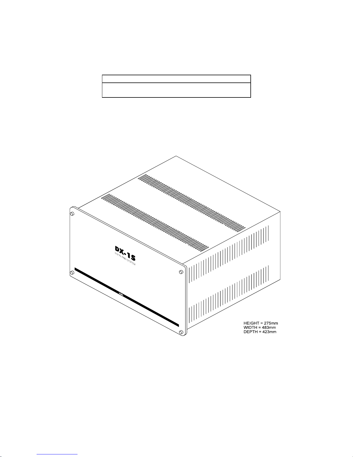
The Cabinet includes a 19 inches (483mm) width metal cabinet. All the cards and boards should install
inside the cabinet. The physical dimension is as following :
Figure 4-4.1 DX-1S CABINET PHYSICAL DIMENSION
4.5.3POWER SWITCH AND FUSE
A power switch and fuse are located at the rear panel of the cabinet and next to the power input connector.
They are the power control of the module. In case of two or more module share one AC / DC power
supply, the switch can turn on / off individual module.
The fuse rating is 5A slow blown type.
3
Page 20
DX-1S DIGITAL PABX - Installation Manual
4.6DX-1S MODULE SYSTEM CABINET
4.6.1HARDWARE ASSEMBLY
DX-1S Module System Cabinet includes the following hardware :
Assembly Included Qty
DX-1S Module Mother Board 1
DX-1S Module Accessories 1
DX-1S Cabinet 1
Hex Key 1
Table 4-6 DX-1S MODULE SYSTEM CABINET ASSEMBLY
4.6.2DESCRIPTION
The Module Mother Board, Module Accessories and Cabinet is assembled together to form a Module
System Cabinet. The Module System Cabinet is ready for the cards to plug in and for the external cables to
connect.
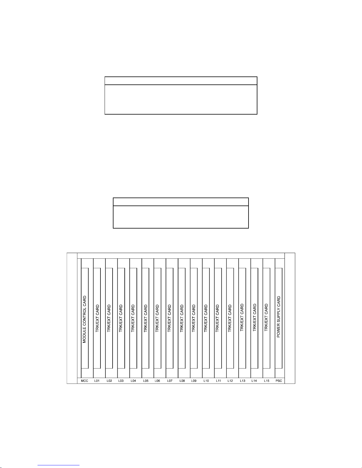
4.6.3CARD POSITION IN MODULE SYSTEM CABINET
There are 17 slots in the Module System Cabinet for the Power Supply Card, Module Control Card,
Peripheral Cards installation as following :
Slot Card Type Marking Qty
1 Module Control Card MCC 1
2 - 16 Peripheral Cards L01 - L15 15
17 Power Supply Card PSC 1
Table 4-7 MODULE SYSTEM CABINET CARD SLOTS
Figure 4-4.2 DX-1S MODULE SYSTEM CABINET FRONT VIEW
4
Page 21

DX-1S DIGITAL PABX - Installation Manual
4.7DX-1S MODULE CONTROL CARD (MCC)
4.7.1HARDWARE ASSEMBLY
DX-1S Module Control Card includes the following hardware :
Assembly Included Qty
DX-1S Module Control Card 1
Table 4-8 DX-1S MODULE CONTROL CARD ASSEMBLY
4.7.2DESCRIPTION
The Module Control Card is labeled as MCC in the card ejectors and is installed in the first slot of Module
System Cabinet. This card includes the Central Processor (CPU), memory, system clock, digital switching
crosspoint, DTMF receivers, tone generator and system control circuit. It performs all call processing and
controls the peripherals for the entire system.
4.7.3INDICATION
There are one Green LED and one Red LED in the front edge of the card to indicate the card status as
following :
Green LED Red LED Status
Flash
(0.2s On, 2.8s Off)
Off System is in initialization
process
Flash
(0.5s On, 0.5s Off)
Off System running in Basic
Mode
Flash
(1.0s On, 1.0s Off)
Off System running in Expanded
Mode
On On CPU do not operate
Flash Flash
(0.5s On, 0.2s Off)
The system has found error in
Programming Data and reset
the data to default value.
Flash Flash
(0.2s On, 0.2s Off,
0.2s On, 0.5s Off)
The system has found the
Flash PROM is failed.
Table 4-9 LED INDICATION IN MODULE CONTROL CARD
4.7.4SYSTEM SOFTWARE UPGRADE
The system may need to upgrade the system software to include the latest features. In order to upgrade the
system software, U2, U37 and U79 integrated circuits in Module Control Card may need to be rewritten the
content with new data or replaced with new version chips (Reference to Upgrade System Software section
for details).
5
Page 22
DX-1S DIGITAL PABX - Installation Manual
4.8DX-1S POWER SUPPLY CARD (PSC)
4.8.1HARDWARE ASSEMBLY
DX-1S Power Supply Card includes the following hardware :
Assembly Included Qty
DX-1S Power Supply Card 1
Table 4-10 DX-1S POWER SUPPLY CARD ASSEMBLY
4.8.2DESCRIPTION
The Module Power Supply Card is installed in the last slot (17th slot) of Module System Cabinet and is
labeled as PSC in the card ejectors. This card inputs DC -48V from the external AC/DC Power Supply
and generates DC +5V, -5V and AC 75V 25Hz Ringing Voltage for the system.
4.8.3FUSE SETTING
There are three fuses for over current protection :
Fuse Value Function
F1 1.5A Quick Acting Fuse Ring Module Input Protection
F2 2A Quick Acting Fuse
5V Power Module Input Protection
F3 0.5A Quick Acting Fuse Ring Module Output Protection
Table 4-11 POWER SUPPLY CARD FUSES VALUE
4.8.4INDICATION
PSC has 3 LEDs in the front edge of the card. They indicate the +5V, -5V and Ringing voltage output
condition. If the LED turn on, it indicates the output from the card is normal.
6
Page 23
DX-1S DIGITAL PABX - Installation Manual
4.9DX-1S TRK/EXT CARD - 4 TRK + 12 EXT (T/E)
4.9.1HARDWARE ASSEMBLY
DX-1S TRK/EXT Card includes the following hardware :
Assembly Included Qty
DX-1S TRK/EXT Card 1
Table 4-12 DX-1S TRK/EXT CARD ASSEMBLY
4.9.2DESCRIPTION
TRK/EXT Card is one of the peripheral cards and is labeled as T/E in the card ejectors. It can be installed
in second to sixteenth line card slots. Each card has 4 trunk interfaces and 12 telephone interfaces. The
trunk and extension lines are connected to the card through the Line Connectors of Module System
Cabinet.
4.9.3INDICATION
There are 16 Green LEDs in the front edge of the card to indicate the status of each trunk and extension.
As the card is installed in Module System Cabinet, counting from up to down, the first four LEDs are
Trunk LED and indicate the status of first four trunks. The following LEDs are Extension LED and
indicate the hook status of the extensions. The first LED indicates the status of the first trunk and the
second one indicates the second trunk and so on. The fifth LED indicates the hook status of the first
extension in this card and the status of the following extensions are represented by the following LED.
The indication of Trunk LED is related to the polarity of trunk line. The polarity reversal and clear-back
signal also affect the LED indication. The Trunk LED indicates the trunk status as following :
Trunk Status LED Indication (Tip is
positive and Ring is
negative in idle condition)
LED Indication (Tip is
negative and Ring is
positive in idle condition)
On-Hook On On
Ringing Flash in ring frequency Flash in ring frequency
Off-Hook Off On
Polarity Reversed From Off change to On From On change to Off
Clear-Back From On change to Off From Off change to On
Table 4-13 INDICATION OF TRUNK LED IN TRK/EXT CARD
When the Extension LED turn on, it indicates the telephone connected to this extension is off-hook. The
LED turn off indicates the extension is ringing or in on-hook status.
LED Extension Status
On Off-Hook
Off On-Hook
Off Ringing
Table 4-14 INDICATION OF EXTENSION LED IN TRK/EXT CARD
7
Page 24

DX-1S DIGITAL PABX - Installation Manual
4.10DX-1S EXT CARD - 16 EXT (EXT)
4.10.1HARDWARE ASSEMBLY
DX-1S EXT Card includes the following hardware :
Assembly Included Qty
DX-1S EXT Card 1
Table 4-15 DX-1S EXT CARD ASSEMBLY
4.10.2DESCRIPTION
EXT Card is one of the peripheral cards and is labeled as EXT in the card ejectors. It can be installed in
any line card slots (2nd ~ 16th slots). Each card has 16 telephone interfaces. The extension lines are
connected to the card through the Line Connectors of Module System Cabinet.
4.10.3INDICATION
There are 16 Green LEDs in the front edge of the card to indicate the hook status of each extension. As the
card is installed in Module System Cabinet, counting from up to down, the first LED indicates the first
extension hook status and the second one indicates the second extension and so on.
The LED turn on indicates the telephone connected to this extension is in off-hook status. The LED turn
off indicates the extension is ringing or in on-hook status.
LED Extension Status
On Off-Hook
Off On-Hook
Off Ringing
Table 4-16 LED INDICATION IN EXT CARD
8
Page 25
DX-1S DIGITAL PABX - Installation Manual
4.11DX-1S CALLER ID CARD (CIC)
4.11.1HARDWARE ASSEMBLY
DX-1S Caller ID Card includes the following hardware :
Assembly Included Qty
DX-1S Caller ID Card 1
Table 4-17 DX-1S CALLER ID CARD ASSEMBLY
4.11.2DESCRIPTION
Caller ID Card is one of the peripheral cards and is labeled as CIC in the card ejectors. It can be installed
in any line card slots (2nd ~ 16th slots). Caller ID card provides Caller ID display of intercom call and also
incoming trunk call. Each card has 8 CIC channels and each CIC channel include a FSK and DTMF Caller
ID receiver and a FSK Caller ID transmitter.
The CIC channels are required to connect to trunk lines (in parallel) in order to provide Caller ID display
of incoming trunk call. CIC channels are output at the Line Connectors of Module System Cabinet.
4.11.3INDICATION
There are 8 Green LEDs in the front edge of the card to indicate the status of each CIC channel. As the
card is installed in Module System Cabinet, counting from top to bottom, the first LED indicates the first
CIC channel status and the second one indicates the second CIC channel and so on.
The LED turn on indicates the CIC channel is ready. The LED turn off for about two second indicates the
CIC channel is sending out Caller ID information. Blinking LED indicates CIC channel is receiving FSK
Caller ID information at trunk port. If the LED is always off, it indicates the CIC channel has problem.
LED CIC Channel Status
On Ready
2s Off Sending Caller ID information
Blinking Receiving FSK Caller ID information
Always off Has problem
Table 4-18 LED INDICATION IN CALLER ID CARD
9
Page 26

DX-1S DIGITAL PABX - Installation Manual
4.12SPS-4820 BATTERY BACKUP POWER SUPPLY
4.12.1HARDWARE ASSEMBLY
For SPS-4820 Battery Backup Power Supply includes the following hardware :
Assembly Included Qty
SPS-4820 Power Supply 1
Power Cord with Built-in Surge Protection Module 1
Table 4-19 SPS-4820 BATTERY BACKUP POWER SUPPLY ASSEMBLY
4.12.2DESCRIPTION
SPS-4820 Battery Backup Power Supply is a separate device. It should be installed near Module System
Cabinet. The Power Supply inputs 220 AC power, generates DC -48V for the System and charges up the
backup batteries. Once the AC power is failed, the Power Supply will switch to the backup batteries
automatically and draw the current to the System without interruption until the AC power is recovered.
4.12.3OPERATION
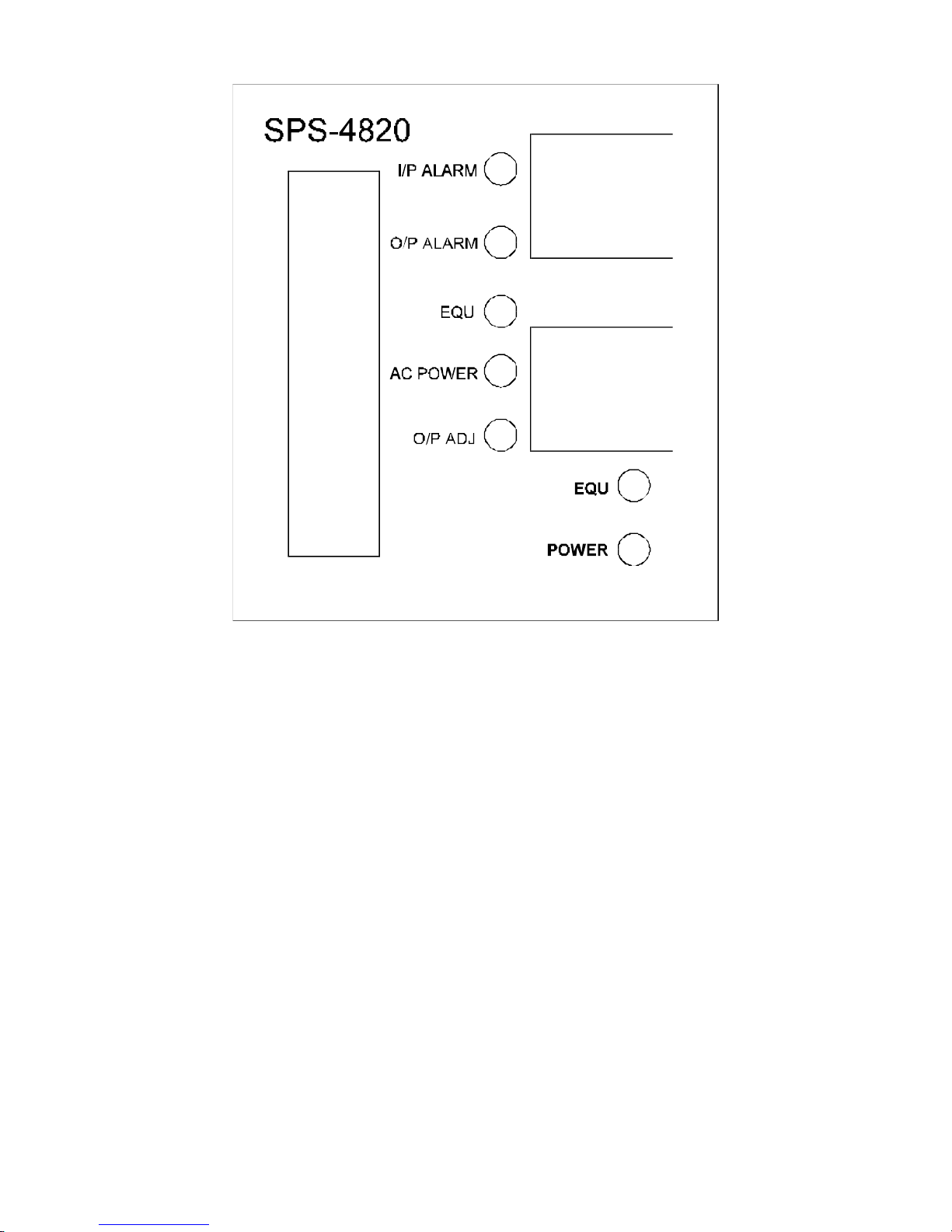
There are a voltmeter and ammeter in the front panel to indicate the output voltage and current.
The push button labeled as “POWER” in the front panel is the power switch of the Power Supply. It is
tackle operation - push the button will turn on the power and push again will turn off. The AC Power LED
will turn on when the power supply is in operation.
If the AC Power is in failure, the Power Supply will switch to the backup batteries automatically and draw
the current to the System without interruption until the AC power is recovered. The internal buzzer will
output alarm signal every 20 seconds to indicate the batteries are in operation if the batteries have
connected.
The push button labeled as “EQU” is to enable the Equalization Charge Mode. The EQU LED indicates if
the Equalization Charge mode is activated.
The I/P ALARM and O/P ALARM LED indicates if the protection function is activated.
The output voltage can be adjusted by the trimmer labeled as “O/P ADJ” in the front panel to meet
different batteries requirement.
10
Page 27
DX-1S DIGITAL PABX - Installation Manual
Figure 4-4.3 SPS-4820 POWER SUPPLY FRONT PANEL
4.12.4INPUT VOLTAGE PROTECTION
If the AC input voltage is lower than 170V or higher than 255V when switching on, the Power Supply will
shut down the output, the I/P Alarm Red LED will light up and the internal buzzer will output alarm signal
to indicate the alarm condition. The Power Supply will restart when the AC input voltage come to normal
range.
When the Power Supply is ON, the Power Supply will still monitor if the AC input voltage is lower than
165V or higher than 285V. When the input voltage is out of the range, the Power Supply will shut down
the output, the I/P Alarm Red LED will light up and the internal buzzer will output alarm signal to indicate
the alarm condition. As the input voltage falls into the acceptable range, the Power Supply will recover to
normal condition.
4.12.5OUTPUT OVER-VOLTAGE PROTECTION
The power supply includes output over-voltage protection. If the output voltage is higher than 59 voltage,
the Power Supply will shut down the output, the O/P Alarm Red LED will light up and the internal buzzer
will output alarm signal to indicate the alarm condition. The Power Supply can be reset to normal
condition by switching off and then switching on the system again.
4.12.6BATTERY OVER-DISCHARGE PROTECTION
The Power Supply also includes output low-voltage protection to protect the backup batteries from over
discharge. Once the AC power is failed, the Power Supply will switch to the backup batteries automatically
and will draw the current to the System without interruption until the AC power is recovered. The
protection circuit will monitor the output voltage. If the output voltage is under 42V, the protection circuit
will shut down the output to avoid damaging the batteries. The O/P Alarm Red LED will light up and the
internal buzzer will output alarm signal to indicate the alarm condition. If the AC power recovers and the
power supply will charge up the batteries. The power supply will not output voltage to the system until the
batteries has charged up to 46V.
11
Page 28

DX-1S DIGITAL PABX - Installation Manual
4.12.7EQUALIZATION CHARGE MODE
Since the backup batteries is always in standby condition but seldom discharge, the batteries will become
inactive and the capacity gradually decrease. The Equalization Charge activates the chemical and
electrochemical of the batteries and recover the capacity. The Equalization Charge is to increase the
charging voltage by 2.5V (56V charging voltage) to charge up the batteries. It is advised to refresh the
batteries by using Equalization Charge once a year. SPS-4820 Power Supply includes the Equalization
Charge mode. Push the EQU button in the front panel and the power supply will activate the Equalization
Charge mode and the EQU LED turn on. The power supply will terminate this mode and switch to normal
condition after 8 hour. It can also terminate the Equalization Charge Mode manually by pushing the EQU
button.
4.12.8INPUT AND OUTPUT
There is a AC inlet for connection with 220V AC power. The 4 Way Output Terminal Block is for battery
and -48V output connection.
4.12.9POWER CORD WITH BUILT-IN SURGE PROTECTOR
There is a Power Cord with Built-in Surge Protector for the Power Supply. The cord connects the Power
Supply to AC power socket, filters out the high voltage surge in AC power line and protects the Power
Supply from damage.
12
Page 29
DX-1S DIGITAL PABX - Installation Manual
4.12.10SPECIFICATION
Parameter Minimum Value Typical Value Maximum Value
AC Input Voltage 170V AC 220V AC 285V AC
AC Input Frequency 47Hz 63Hz
Max. Input Current 8A
Input Undervoltage
Protection Threshold
170V AC
Input Overvoltage
Protection Threshold
265V AC
Output Voltage 53V DC 53.3V DC 54V DC
Adjustable Output
Voltage Range
50V DC 56V DC
Max. Output Current 20A
Load Regulation 1%
Line Regulation 0.5%
Overcurrent Protection
Threshold
20.5A 22A
Output Noise
(0~20MHz)
80mV p-p 150mV p-p
Output Ripple
(weighed)
0.5mV rms 2mV rms
Efficiency 85%
Battery Undervoltage
Protection Threshold
41.5V DC 42V DC 42.5V DC
Output Overvoltage
Protection Threshold
58V DC 59V DC 60V DC
Weight 5.4KG
Table 4-20 SPS-4820 POWER SUPPLY SPECIFICATION
The user can use a similar power supply which has compatible specification to replace SPS-4820.
4.12.11BATTERY CAPACITY
The backup time duration is depended on battery capacity. The battery capacity via backup time is shown
as following table. The Backup time in the table is an approximation only, since different traffic of the
system will give different result.
Battery Capacity Backup time (120 ports) Backup time (240 ports)
10AH 6 hours 4.5 hours
20AH 12 hours 9 hours
40AH 25 hours 18 hours
80AH 50 hours 36 hours
Table 4-21 BACKUP TIME AGAINST BATTERY CAPACITY
13
Page 30
DX-1S DIGITAL PABX - Installation Manual
4.13CAD600A BATTERY BACKUP POWER SUPPLY
4.13.1HARDWARE ASSEMBLY
For CAD600A Battery Backup Power Supply includes the following hardware :
Assembly Included Qty
CAD600A Power Supply 1
Power Cord 1
Table 4-22 CAD600A BATTERY BACKUP POWER SUPPLY ASSEMBLY
4.13.2DESCRIPTION
CAD600A Battery Backup Power Supply is a separate device. It should be installed near Module System
Cabinet. The Power Supply inputs 220 AC power, generates DC -48V for the System and charges up the
backup batteries. Once the AC power is failed, the Power Supply will switch to the backup batteries
automatically and draw the current to the System without interruption until the AC power is recovered.
4.13.3OPERATION
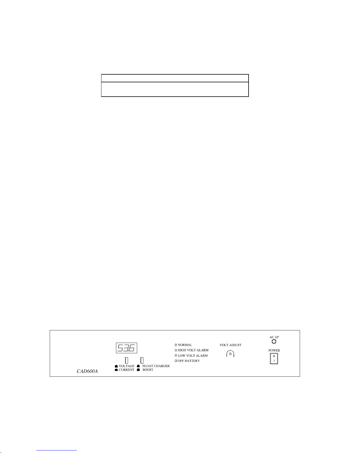
There has a 3 digits LED display in the front panel to indicate the output voltage and current. The push
button labeled VOLTAGE / CURRENT under the LED display is used to toggle the display between
voltage and current.
The switch labeled as “POWER” in the front panel is the power on/off switch. The AC I/P LED will turn
on when AC power input is presence.
If the AC Power is in failure, the Power Supply will switch to the backup batteries automatically and draw
the current to the System without interruption until the AC power is recovered
The push button labeled as “FLOAT CHARGER / BOOST” is to select Float charge or Boost charge
Mode.
The 4 LEDs located in the middle of front panel is for power supply operation condition and alarm
indication.
“NORMAL” : Green LED indicator is on to indicate normal output operation in the presence of AC
input or the battery is discharging without the presence of AC input
“HIGH VOLTS ALARM”: Red LED indicator flashes to indicate output voltage higher than 58V. The
red LED flashes more rapidly as the loading increases
Yellow LED indicator is on to indicate AC input higher than 270V and the power supply has
shutdown.
“LOW VOLTS ALARM”: Red indicator is on to indicate output voltage or battery voltage lower than
43V.
“OFF BATERY”: Red LED indicator is on to indicate battery has discharged to lower than 42V. To
protect the battery from over-discharge, the protection relay is open to cut off the battery discharge.
The output voltage can be adjusted by the trimmer labeled as “VOLT ADJUST” in the front panel to meet
different batteries requirement.
Figure 4-4.4 CAD600A POWER SUPPLY FRONT PANEL
4.13.4INPUT VOLTAGE PROTECTION
If the AC input voltage is higher than 270V when switching on, the Power Supply will shut down the
output, the “HIGH VOLTS ALARM” will change to yellow. The Power Supply will restart when the AC
input voltage return to normal range.
14
Page 31

DX-1S DIGITAL PABX - Installation Manual
4.13.5OUTPUT OVER-VOLTAGE PROTECTION
The power supply includes output over-voltage protection. If the output voltage is higher than 58 voltage,
the output will stay in the “Hiccup” mode. The “HIGH VOLTS ALARM” red LED flashes more rapidly as
the loading increases. The output will recover once it is lower than 58V.
4.13.6BATTERY OVER-DISCHARGE PROTECTION
The Power Supply also includes output low-voltage protection to protect the backup batteries from over
discharge. Once the AC power is failed, the Power Supply will switch to the backup batteries automatically
and will draw the current to the System without interruption until the AC power is recovered. The
protection circuit will monitor the output voltage. If the output voltage is under 42V, the protection circuit
will cut off the battery to avoid damaging the batteries. The “OFF BATTERY” Red LED will light up. If
the AC power recovers and the power supply will charge up the batteries.
4.13.7BOOST CHARGE MODE
Since the backup batteries is always in standby condition but seldom discharge, the batteries will become
inactive and the capacity gradually decrease. The Boost Charge activates the chemical and electrochemical
of the batteries and recover the capacity. The Boost Charge is to increase the charging voltage by 2.5V
(56V charging voltage) to charge up the batteries. It is advised to refresh the batteries by using Boost
Charge once a year. CAD600A Power Supply includes the Boost Charge mode. Push the “FLOAT
CHARGER / BOOST” button in the front panel and the power supply will activate the Boost Charge mode.
It can terminate the Boost Charge Mode by pushing the button again. The Boost Charge process should last
about 8 hours.
4.13.8INPUT AND OUTPUT
There is a AC inlet for connection with 220V AC power. The two 2-Way Output are for battery and -48V
output connection.
15
Page 32
DX-1S DIGITAL PABX - Installation Manual
4.13.9SPECIFICATION
Parameter Minimum Value Typical Value Maximum Value
AC Input Voltage 160V AC 220V AC 270V AC
AC Input Frequency 47Hz 440Hz
Max. Input Current 5A
Input Overvoltage
Protection Threshold
270V AC
Output Voltage 53V DC 53.5V DC 54V DC
Adjustable Output
Voltage Range
43V DC 57V DC
Max. Output Current 10.5A
Load Regulation 0.4% 1%
Line Regulation 0.1% 1%
Overcurrent Protection
Threshold
11A 13A
Output Noise
(0~20MHz)
< 100mV p-p
Efficiency 85%
Battery Undervoltage
Protection Threshold
41V DC 42V DC 43V DC
Output Overvoltage
Protection Threshold
58V DC 59V DC 60V DC
Weight 6.5KG
Table 4-23 CAD600A POWER SUPPLY SPECIFICATION
The user can use a similar power supply which has compatible specification to replace CAD600A.
4.13.10BATTERY CAPACITY
The backup time duration is depended on battery capacity. The battery capacity via backup time is shown
as following table. The Backup time in the table is an approximation only, since different traffic of the
system will give different result.
Battery Capacity Backup time (120 ports) Backup time (240 ports)
10AH 6 hours 4.5 hours
20AH 12 hours 9 hours
40AH 25 hours 18 hours
80AH 50 hours 36 hours
Table 4-24 BACKUP TIME AGAINST BATTERY CAPACITY
16
Page 33
DX-1S DIGITAL PABX - Installation Manual
4.14MFC-1S PC INTERFACE CARD WITH CONSOLE SOFTWARE
4.14.1HARDWARE ASSEMBLY
MFC-1S PC Interface Card includes the following hardware :
Assembly Include Qty
MFC-1S PC Interface Card Installed 1
4-Core Cable with RJ-11 Modular Jack 1
MFC-1S System Software Disk 1
MFC-1S Reset Disk 1
Table 4-25 MFC-1S PC INTERFACE CARD ASSEMBLY
4.14.2CONFIGURING MFC-1S PC INTERFACE CARD
You can install the console in the following order
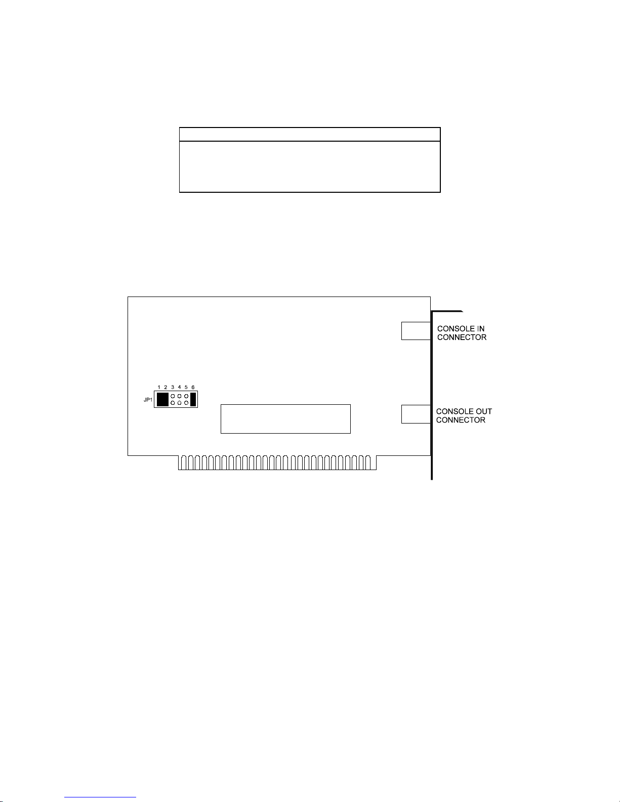
Setup Hardware Interrupt Level (JP1, the jumper block to set interrupt level).
The default hardware interrupt level (IRQ) is 7; PIN1, PIN 2 and PIN 6 are shorted.
Figure 4-4.5 MFC-1S PC INTERFACE CARD
4.14.3DESCRIPTION
The MFC-1S PC Interface Card is an optical isolated serial port card. It installed in a standard PC station
to form a MFC-1S Console. The console system will transmit or receive the system data through the PC
Interface Card to communicate with DX-1S System. Since the communication ports in the card are optical
isolated, they prevent the surge which induces in the console bus to damage the system.
The MFC-1S System Software Package includes a console software diskette and a reset diskette. The
Console Software to operate the Console. The Reset Disk is used to reset the Console Setup Mode
Password to default value in case the user had programmed his/her own password but lost it.
4.14.4CONNECTORS IN MFC-1S
There are two MJ-64 Module Socket connectors on the card for connection with DX-1S System and
another console. The Console-in connector is for connection with DX-1S System or the prior console. The
Console-out connector is to connect the next console.
17
Page 34
DX-1S DIGITAL PABX - Installation Manual
4.15MFC-1S CONSOLE
4.15.1HARDWARE ASSEMBLY
MFC-1S PC Console is a dedicated operator console for DX-1S System. The Console includes the
following hardware :
MFC-1S Console include Qty
PC Computer Station with MFC-1S PC Interface Card Installed 1
9” VGA Monochrome Monitor 1
Numeric Keyboard 1
4-Core Cable with RJ-11 Modular Jack 1
Power Cord 1
MFC-1S System Software Disk 1
MFC-1S Reset Disk 1
Table 4-26 MFC-1S CONSOLE ASSEMBLY
Instead of buying the whole console system, the user can order a MFC-1S PC Interface Card and Console
Software Package to install in a standard PC station to form a MFC-1S Console.
There are two versions of MFC-1S which have the same function but with different type of connectors for
different ports.
4.15.2DESCRIPTION
MFC-1S is a multi-function operator console which provides the following functions :
Display Function : System Status
Busy Lamp Field
Clock Display
` Extension Status Inquiry
Incoming Call Identification
Operator Call Processing
Access System Programming
Access System Maintenance
Access System Diagnostic
Extension Feature Setting
SMDR Data Printout
Programming Data Printout
18
Page 35
DX-1S DIGITAL PABX - Installation Manual
4.16DX-1S DISA VOICE CARD
4.16.1HARDWARE ASSEMBLY
DX-1S DISA Voice Card includes the following hardware :
Assembly Include Qty
DX-1S DISA Voice Card 1
Table 4-27 DX-1S DISA VOICE CARD ASSEMBLY
4.16.2DESCRIPTION
The DISA Voice Card is installed in Module Control Card. Each Module Control Card can install up to
three DISA Voice Cards.
Each card has two channels. Each channel includes a fax signal detector, a voice chip for voice messages
storage, DTMF detector and tone detector. Every channel can record four messages with total length of 90
seconds.
The DISA Voice Card provides the following features :
DISA with Voice Message
Trunk No Answer Voice Announcement
Voice Message Recording
4.17DX-1S POWER FAILURE TRANSFER MODULE
4.17.1HARDWARE ASSEMBLY
DX-1S Power Failure Transfer Module includes the following hardware :
Assembly Include Qty
DX-1S Power Failure Transfer Card 1
DX-1S Power Failure Transfer Module Panel 1
Table 4-28 DX-1S POWER FAILURE TRANSFER MODULE ASSEMBLY
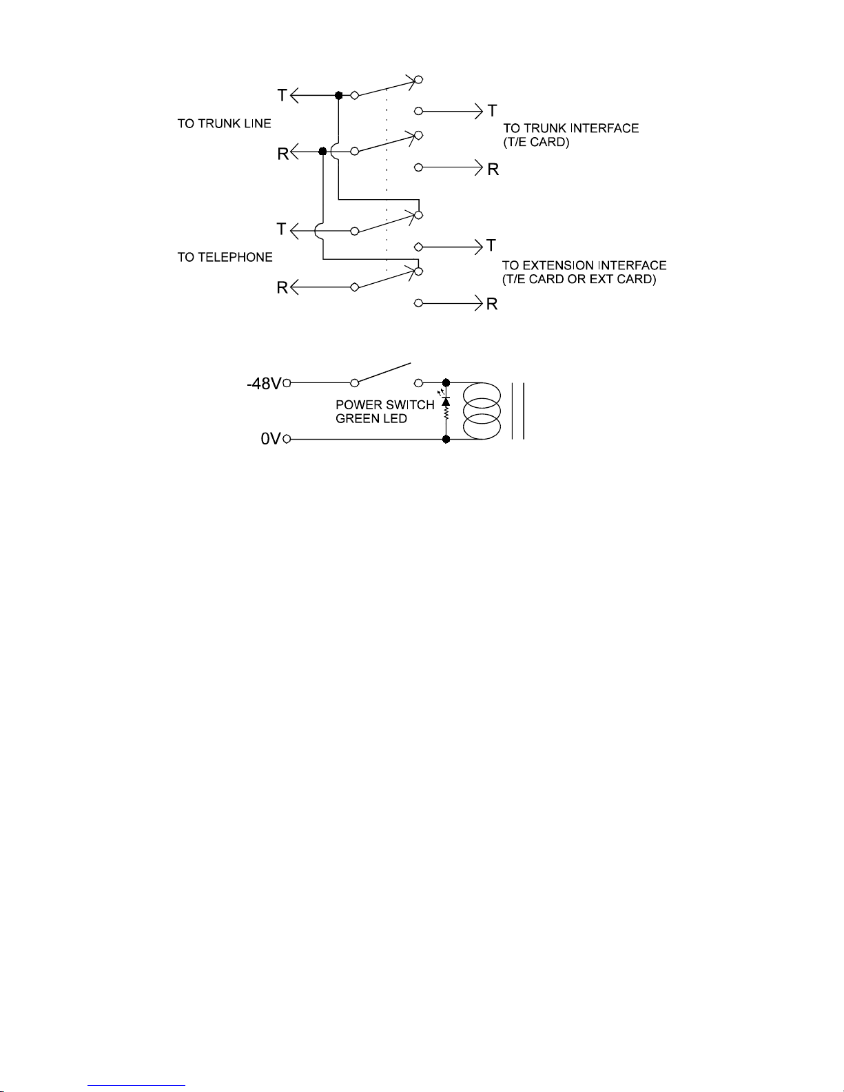
4.17.2DESCRIPTION
The Power Failure Transfer Module is installed in the Lower Rear Panel of Module System Cabinet. The
module includes 12 sets of switch and connect 12 sets of extension telephones to the extension ports in
normal condition to perform extension function. If the power failure condition is happened or the module
is switched to OFF condition manually, the module will disconnect the circuit between the telephones &
extension ports and will connect the telephones directly to the trunk lines. This feature allows the
telephones directly connect to the trunk lines during the system is temporary down for maintenance purpose
or in power failure condition, so that some telephones will be able to make outgoing calls or receive
incoming calls.
19
Page 36
DX-1S DIGITAL PABX - Installation Manual
Figure 4-4.6 DX-1S POWER FAILURE TRANSFER MODULE CIRCUIT DIAGRAM
20
Page 37

DX-1S DIGITAL PABX - Installation Manual
5.HARDWARE INSTALLATION
5.1BASIC PRECAUTIONS FOR INSTALLATION
Before installing or replacing the cards, the ground connection of Module System Cabinet must be well
connected.
When installing or replacing the cards to Module System Cabinet, ensure the power has switched off.
Do not touch the board components or connectors without static-discharge precautions.
Wear antistatic wrist strap when handling the cards.
Handle the cards by the edges and avoid contact the components and connectors.
The cards should be placed in anti-static package when not in use.
Retain the packing material until the installation completed.
5.2PREPARE BASIC INSTALLATION
Identify all trunk lines, extension lines, door phone lines and other equipment to be connected to the
system.
Confirm the system configuration and determine the quantities and types of the cards to be installed.
Prepare the wiring diagram and connection table for the cables in MDF.
Select the location for system installation (Reference to Installation Site Requirements Section).
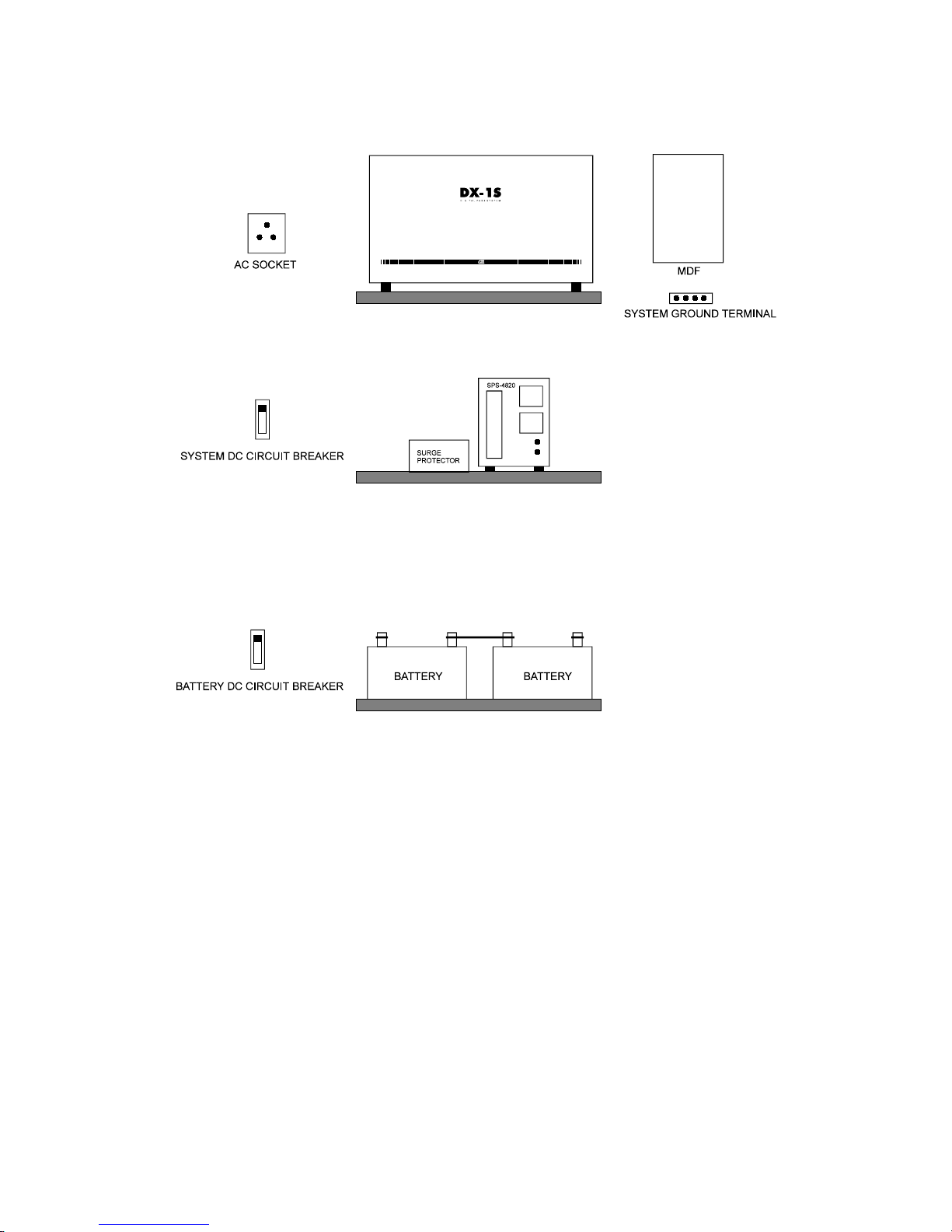
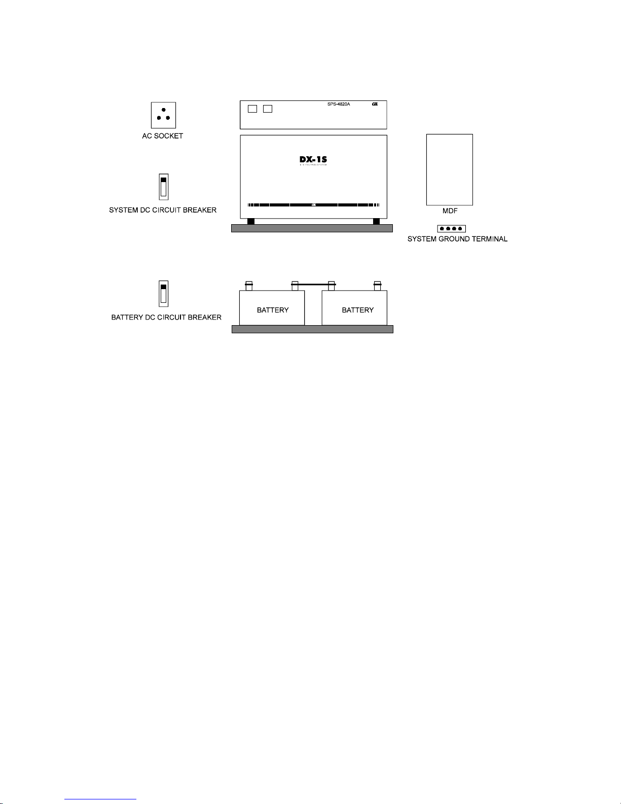
Install the shelf or rack for placing Module System Cabinet, Power Supply, MDF and backup batteries.
Install System Ground Terminal to concentrate all hardware ground.
Use #14 AWG cables to connect different hardware separately to System Ground Terminal.
Connect an approved building ground (cold water pipe etc.) directly using a #6 AWG insulated green
wire to the system location but do not connect to System Ground Terminal before the verification of
ground connection.
The MDF protection ground should be connected to System Ground Terminal directly using a #10
AWG insulated green wire.
All conductive assemblies, such as doors, shelves, racks and similar assemblies should connect to
System Ground Terminal.
Install a 10A circuit breaker for system power ON/OFF control and over-current protection.
Install AC power socket for the system.
Install the trunk lines to MDF.
Install the extension lines of telephones and door phone to MDF.
Install the equipment to provide external music source and connect the output to MDF.
Install the Paging Amplifier System to provide paging function and connect the input to MDF.
Connect the door lock control lines to MDF.
Install the 32-core cables with 36 way centronic plug connectors from MDF to Module System Cabinet
for Line Connectors connection.
Install the 4-core cable with 9 way D-type female connector from MDF to Module System Cabinet for
Console Connector connection.
Install the 6-core cable with 9 way D-type male connector from MDF to Module System Cabinet for
Music/Page/Relay Connector connection.
1
Page 38
DX-1S DIGITAL PABX - Installation Manual
Figure 5-5.1 HARDWARE PLACEMENT SUGGESTION (WITH SPS-4820 POWER SUPPLY)
2
Page 39
DX-1S DIGITAL PABX - Installation Manual
Figure 5-5.2 HARDWARE PLACEMENT SUGGESTION (WITH SPS-4820A POWER SUPPLY)
5.3SYSTEM GROUND TERMINAL
The System Ground Terminal can be a brass rod with several cable mounting screw or a large current
terminal block with all pin short together. The System Ground Terminal must be very low resistance and
able to withstand large current. The function of System Ground Terminal is to concentrate all ground
cables from different hardware and connect to the approval building ground through a #6 AWG wire.
5.4BACKUP BATTERIES INSTALLATION
Place the Backup Batteries to the assigned location.
Never short the battery terminal.
Install a 25A circuit breaker in the Negative Terminal of backup batteries for ON/OFF control and
over-current protection.
Reference to Figure 5-2 for battery connection.
5.5MODULE SYSTEM CABINET INSPECTION
Unpack the Module System Cabinet.
Visually inspect the cabinet if there is any damage during transportation.
Remove the front panel.
Check if all the card guides are in the mounting position.
Check all the connectors in the Rear Panel are in good condition.
5.6MOTHER BOARD DIP SWITCH SETTING
Remove the Upper and Lower Rear Panels from Module System Cabinet.
Check if all the cables of Line Card Connector in the rear panel are well connected to the socket
connectors in the Module Mother Board.
Set all the four positions of Dip Switch SW1 to OFF position.
Install the Upper and Lower Rear Panels to the Cabinet.
3
Page 40
DX-1S DIGITAL PABX - Installation Manual
5.7SPS-4820 POWER SUPPLY INSPECTION
Unpack the SPS-4820 Power Supply.
Visually inspect the Power Supply is free from damage during transportation.
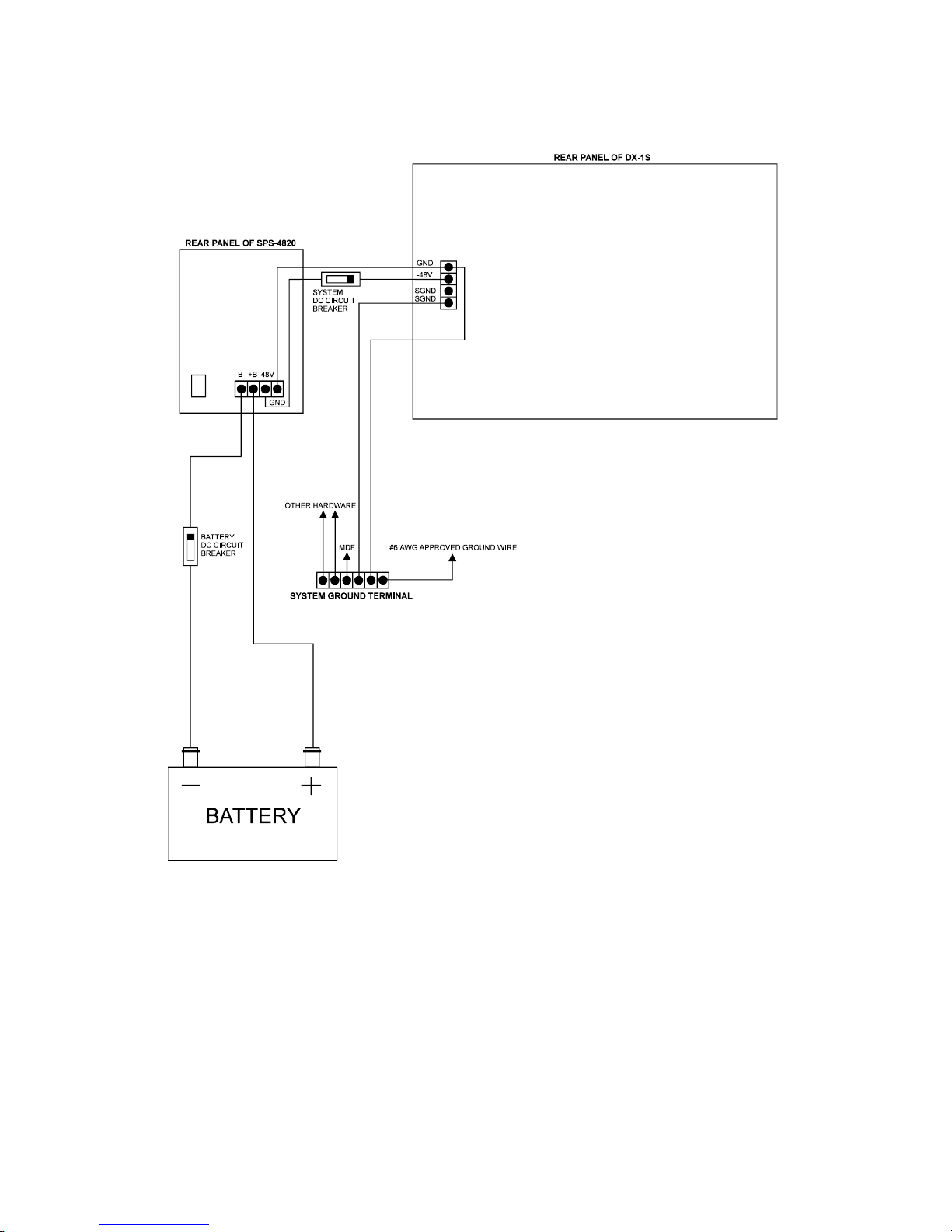
5.8CONNECTION BETWEEN SYSTEM CABINET AND SPS-4820 POWER SUPPLY
Place Module System Cabinet and Power Supply to the assigned position.
Connect Pin 4 - SGND (Surge Ground) of the Power Input Terminal in Module System Cabinet to the
System Ground Terminal with minimum #14 AWG insulated green wires.
Connect Pin 1 - GND (Battery Ground) of the Power Input Terminal in Module System Cabinet to the
System Ground Terminal with minimum #14 AWG insulated green wires.
Connect the Pin 1 - GND of the Power Input Terminal of Module System Cabinet to Pin 4 - GND of
the Power Output Terminal of SPS-4820 Power Supply with minimum #14 AWG insulated black wires.
Connect the Pin 2 - -48V of the Power Input Terminal of Module System Cabinet to the System DC
Circuit Breaker with minimum #14 AWG insulated orange wires.
Connect the Pin 3 - -48V of the Power Output Terminal of SPS-4820 Power Supply to the System DC
Circuit Breaker with minimum #14 AWG insulated yellow wires.
Connect the Pin 2 - BATT+ of the Power Output Terminal of SPS-4820 Power Supply to the Positive
Terminal of backup batteries with minimum #14 AWG insulated gray wires.
Connect the Pin 1 - BATT- of the Power Output Terminal of SPS-4820 Power Supply to the Battery
DC Circuit Breaker with minimum #14 AWG insulated red wires.
Connect the Negative Terminal of backup batteries to the Battery DC Circuit Breaker with minimum
#14 AWG insulated red wires.
Check all the connections are well connected and low resistance.
The length of the cables between Module System Cabinet, Power Supply and backup batteries should
not be over 2 meters. The over length cables will cause unstable to the system.
Verify Ground Connection (Reference to Verify Ground Connection).
Connect the Power Cord with Built-in Surge Protector from SPS-4820 Power Supply to the AC Power
Socket.
Do not power up the Power Supply.
The System Power DC Circuit Breaker is in OFF position.
The Battery DC Circuit Breaker is in OFF position.
Power Output
Terminal
Description
Pin 1 Battery +
Pin 2 Battery Pin 3 -48V output
Pin 4 Ground
Table 5-1 SPS-4820 POWER OUTPUT TERMINAL
Power Input Terminal Description
Pin 1 Battery Ground
Pin 2 -48V input
Pin 3 Surge Ground
Pin 4 Surge Ground
Table 5-2 MODULE SYSTEM CABINET POWER INPUT TERMINAL
4
Page 41
DX-1S DIGITAL PABX - Installation Manual
Figure 5-5.3 MODULE SYSTEM CABINET & POWER SUPPLY CONNECTION DIAGRAM
5
Page 42
DX-1S DIGITAL PABX - Installation Manual
5.9VERIFY GROUND CONNECTION
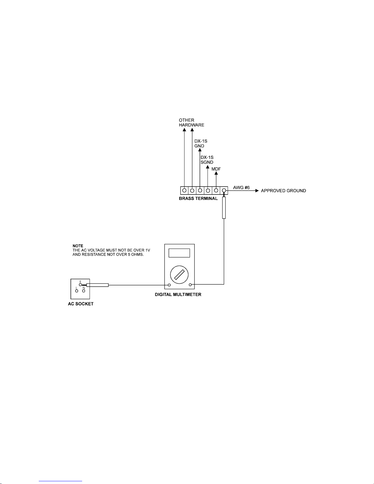
Use a digital multi-meter to measure the AC voltage between the ground pin of the AC power socket
(the Ground of Electrical System) and the #6 AWG approved ground wire. The voltage should not be
over 1V. If the voltage is over 1 voltage, locate another approval ground.
Measure the resistance between the ground pin of the AC power socket (the Ground of Electrical
System) and the #6 AWG approved ground wire that the resistance should not over 5 ohms. If the
resistance is over 5 ohms, take action to reduce the resistance to less than 5 ohms.
Connect the #6 AWG approved round wire to the System Ground Terminal.
Figure 5-5.4 VERIFY GROUND CONNECTION DIAGRAM
6
Page 43

DX-1S DIGITAL PABX - Installation Manual
5.10CONNECTORS IN REAR PANEL OF MODULE SYSTEM CABINET
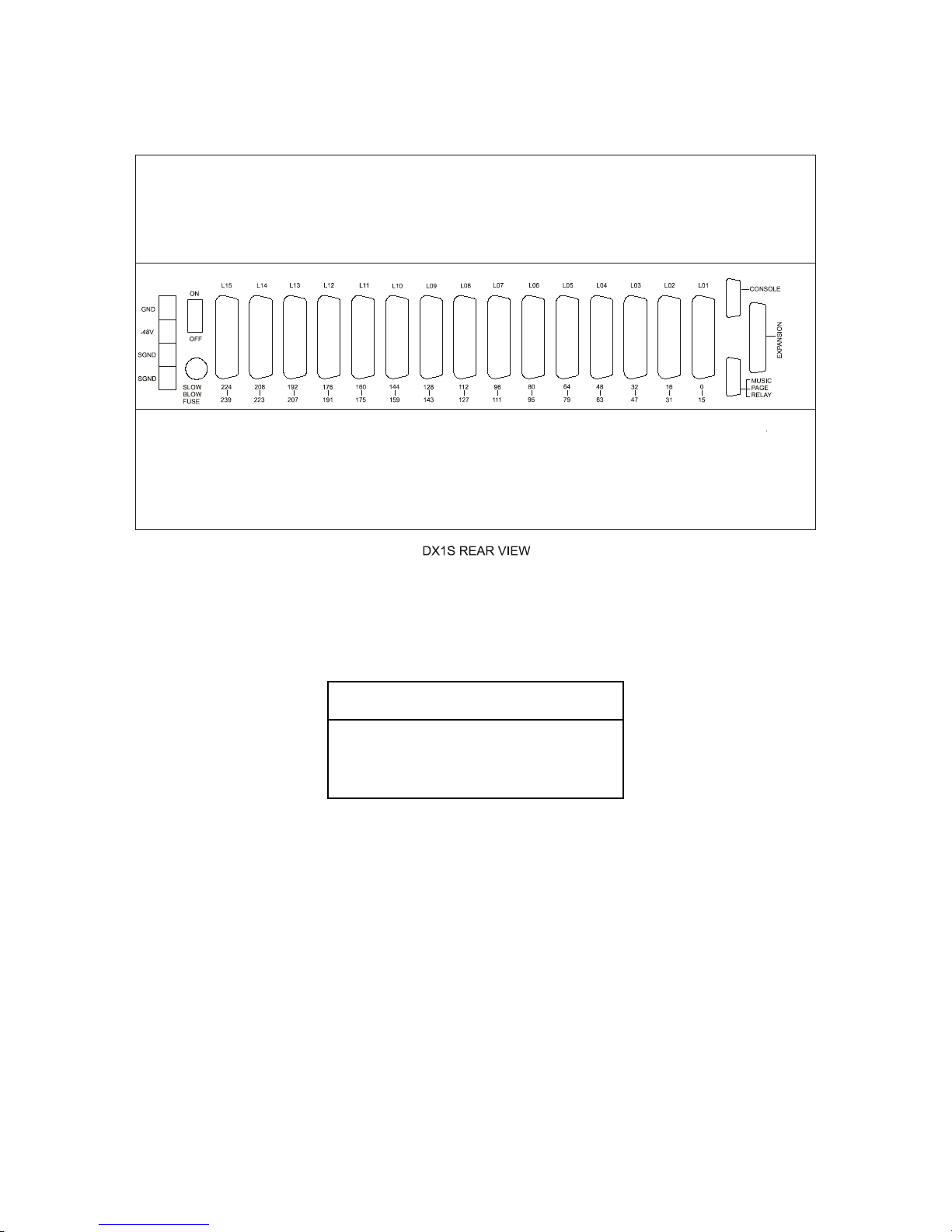
The connectors in the rear panel are for the external cables connection as following :
Connector Type Function
Power Input
Terminal
4 Way Terminal Block For -48V Power Supply &
Surge Ground connection
Console
Connector
9 Way D-Type (DB-9)
Male Connector
For MFC-1S Console
connection
Music/Page/
Relay Connector
9 Way D-Type (DB-9)
Female Connector
For External Music Input,
Page Output & Relay
Contact connection
Expansion
Connector
25 Way D-Type (DB-25)
Female Connector
Reserve for Future
Expansion
Line Connector
L01
36 Way Centronic Socket
Connector
For 1st Peripheral Card
output connection
Line Connector
L02
36 Way Centronic Socket
Connector
For 2nd Peripheral Card
output connection
Line Connector
L03
36 Way Centronic Socket
Connector
For 3rd Peripheral Card
output connection
Line Connector
L04
36 Way Centronic Socket
Connector
For 4th Peripheral Card
output connection
Line Connector
L05
36 Way Centronic Socket
Connector
For 5th Peripheral Card
output connection
Line Connector
L06
36 Way Centronic Socket
Connector
For 6th Peripheral Card
output connection
Line Connector
L07
36 Way Centronic Socket
Connector
For 7th Peripheral Card
output connection
Line Connector
L08
36 Way Centronic Socket
Connector
For 8th Peripheral Card
output connection
Line Connector
L09
36 Way Centronic Socket
Connector
For 9th Peripheral Card
output connection
Line Connector
L10
36 Way Centronic Socket
Connector
For 10th Peripheral Card
output connection
Line Connector
L11
36 Way Centronic Socket
Connector
For 11th Peripheral Card
output connection
Line Connector
L12
36 Way Centronic Socket
Connector
For 12th Peripheral Card
output connection
Line Connector
L13
36 Way Centronic Socket
Connector
For 13th Peripheral Card
output connection
Line Connector
L14
36 Way Centronic Socket
Connector
For 14th Peripheral Card
output connection
Line Connector
L15
36 Way Centronic Socket
Connector
For 15th Peripheral Card
output connection
Table 5-3 MODULE SYSTEM CABINET REAR PANEL CONNECTORS
7
Page 44
DX-1S DIGITAL PABX - Installation Manual
Figure 5-5.5 DX-1S MODULE SYSTEM CABINET REAR PANEL VIEW
5.11CONNECT CONSOLE CABLE FOR MODULE SYSTEM CABINET
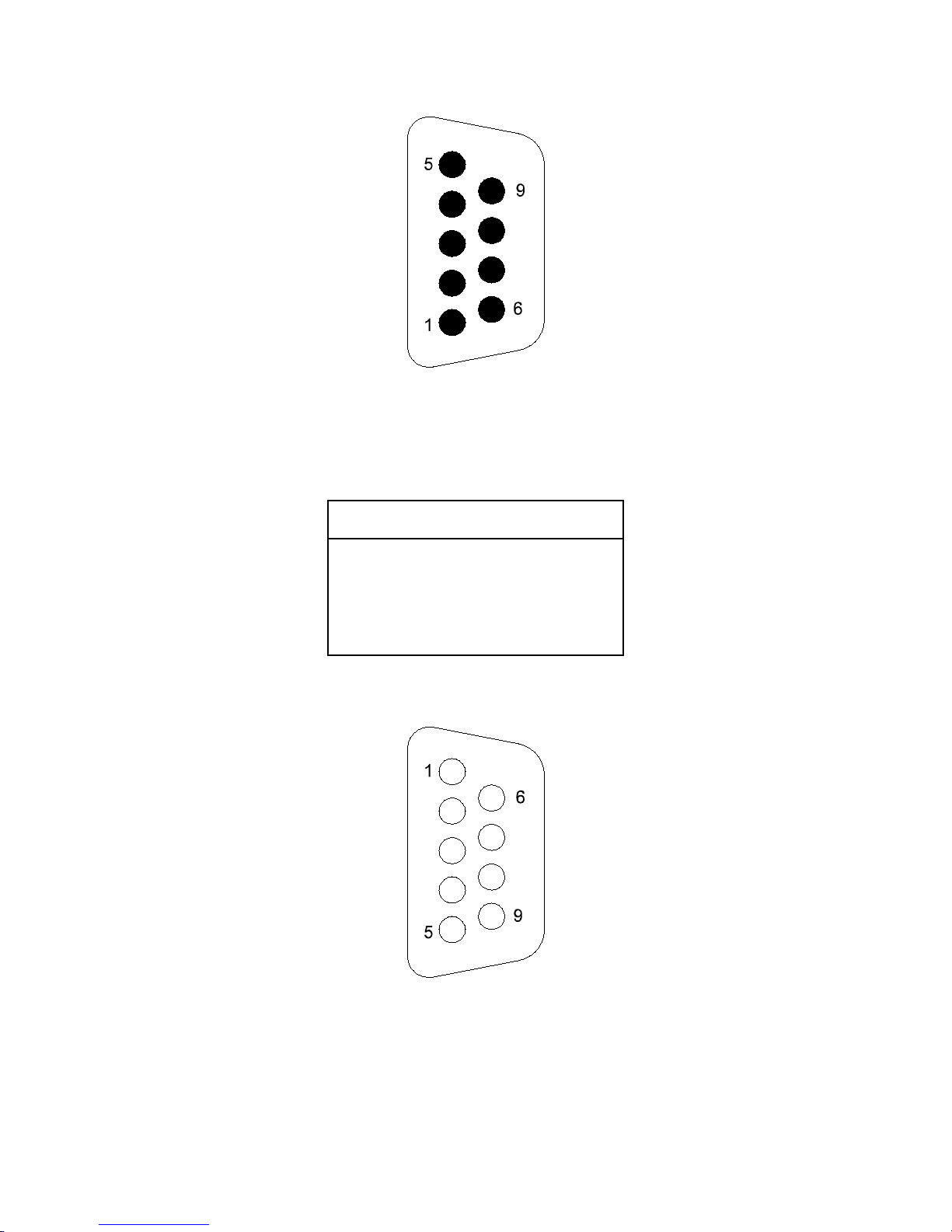
Connect the 4-core cable from Console Connectors of Module System Cabinets to MDF.
Console Connector
(DB-9 Male)
Description
Pin 3 CTX+
Pin 4 CTXPin 2 CRX+
Pin 6 CRX-
Table 5-4 CONSOLE CONNECTOR PIN ASSIGNMENT
8
Page 45
DX-1S DIGITAL PABX - Installation Manual
Figure 5-5.6 CONSOLE CONNECTOR DIAGRAM
5.12CONNECT MUSIC/PAGE/RELAY CABLE FOR MODULE SYSTEM CABINET
Connect the 6-core cable from Music/Page/Relay Connectors of Module System Cabinets to MDF.
M/P/R Connector
(DB-9 Female)
Description
Pin 1 Music Input
Pin 6 Music Input
Pin 2 Paging Output
Pin 7 Paging Output
Pin 4 Contact 1
Pin 9 Contact 2
Table 5-5 M/P/R CONNECTOR PIN ASSIGNMENT
Figure 5-5.7 MUSIC/PAGE/RELAY CONNECTOR DIAGRAM
9
Page 46
DX-1S DIGITAL PABX - Installation Manual
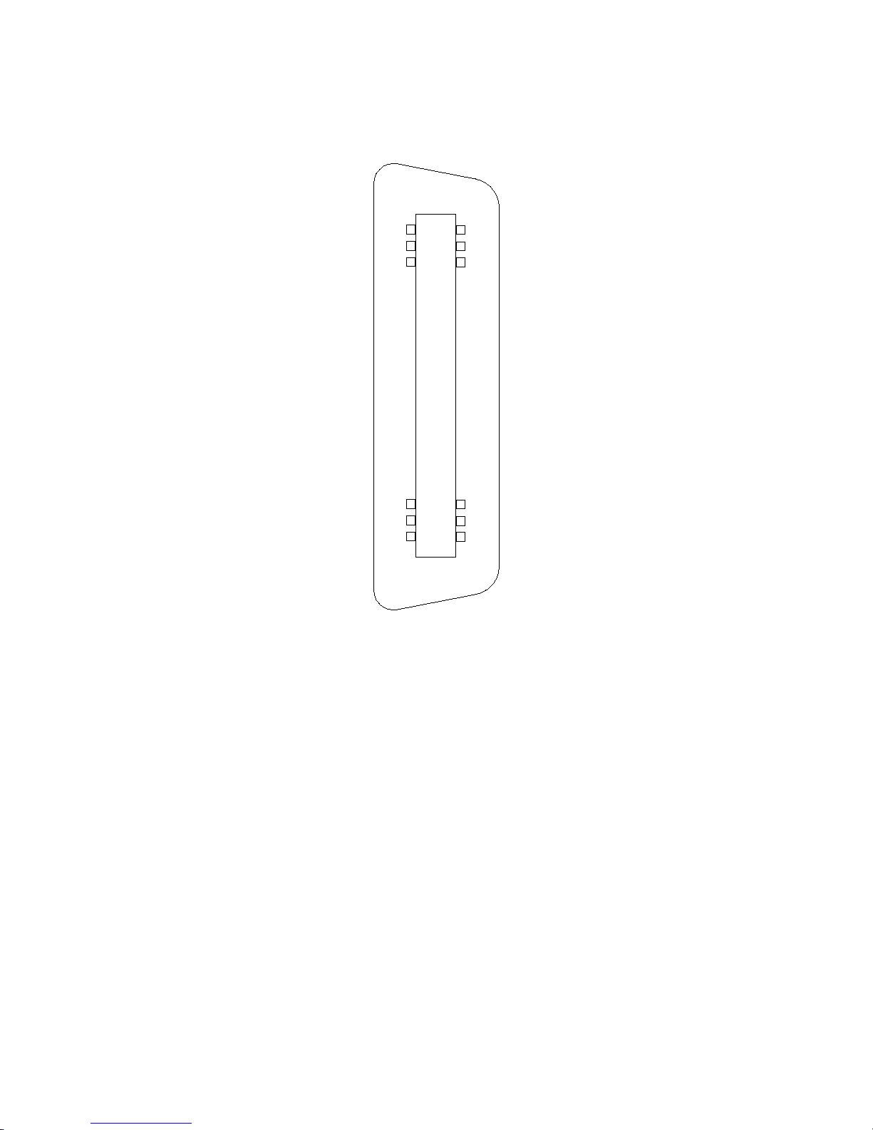
5.13CONNECT LINE CONNECTOR CABLES FOR MODULE SYSTEM CABINET
Connect the 32-core cables from Line Connectors L01-L15 of Module System Cabinet to MDF.
19
18
1
36
Figure 5-5.8 LINE CONNECTOR DIAGRAM
10
Page 47

DX-1S DIGITAL PABX - Installation Manual
5.13.1LINE CONNECTOR L01
Pin TRK/EXT Card is installed EXT Card is installed
1 Trunk 1 Tip Extension 0 Tip
19 Trunk 1 Ring Extension 0 Ring
2 Trunk 2 Tip Extension 1 Tip
20 Trunk 2 Ring Extension 1 Ring
3 Trunk 3 Tip Extension 2 Tip
21 Trunk 3 Ring Extension 2 Ring
4 Trunk 4 Tip Extension 3 Tip
22 Trunk 4 Ring Extension 3 Ring
5 Extension 4 Tip Extension 4 Tip
23 Extension 4 Ring Extension 4 Ring
6 Extension 5 Tip Extension 5 Tip
24 Extension 5 Ring Extension 5 Ring
7 Extension 6 Tip Extension 6 Tip
25 Extension 6 Ring Extension 6 Ring
8 Extension 7 Tip Extension 7 Tip
26 Extension 7 Ring Extension 7 Ring
9 Extension 8 Tip Extension 8 Tip
27 Extension 8 Ring Extension 8 Ring
10 Extension 9 Tip Extension 9 Tip
28 Extension 9 Ring Extension 9 Ring
11 Extension 10 Tip Extension 10 Tip
29 Extension 10 Ring Extension 10 Ring
12 Extension 11 Tip Extension 11 Tip
30 Extension 11 Ring Extension 11 Ring
13 Extension 12 Tip Extension 12 Tip
31 Extension 12 Ring Extension 12 Ring
14 Extension 13 Tip Extension 13 Tip
32 Extension 13 Ring Extension 13 Ring
15 Extension 14 Tip Extension 14 Tip
33 Extension 14 Ring Extension 14 Ring
16 Extension 15 Tip Extension 15 Tip
34 Extension 15 Ring Extension 15 Ring
17 Not Used Not Used
35 Not Used Not Used
18 Not Used Not Used
36 Not Used Not Used
Table 5-6 LINE CONNECTOR L01 PIN ASSIGNMENT
11
Page 48

DX-1S DIGITAL PABX - Installation Manual
5.13.2LINE CONNECTOR L02
Pin TRK/EXT Card is installed EXT Card is installed
1 Trunk 5 Tip Extension 16 Tip
19 Trunk 5 Ring Extension 16 Ring
2 Trunk 6 Tip Extension 17 Tip
20 Trunk 6 Ring Extension 17 Ring
3 Trunk 7 Tip Extension 18 Tip
21 Trunk 7 Ring Extension 18 Ring
4 Trunk 8 Tip Extension 19 Tip
22 Trunk 8 Ring Extension 19 Ring
5 Extension 20 Tip Extension 20 Tip
23 Extension 20 Ring Extension 20 Ring
6 Extension 21 Tip Extension 21 Tip
24 Extension 21 Ring Extension 21 Ring
7 Extension 22 Tip Extension 22 Tip
25 Extension 22 Ring Extension 22 Ring
8 Extension 23 Tip Extension 23 Tip
26 Extension 23 Ring Extension 23 Ring
9 Extension 24 Tip Extension 24 Tip
27 Extension 24 Ring Extension 24 Ring
10 Extension 25 Tip Extension 25 Tip
28 Extension 25 Ring Extension 25 Ring
11 Extension 26 Tip Extension 26 Tip
29 Extension 26 Ring Extension 26 Ring
12 Extension 27 Tip Extension 27 Tip
30 Extension 27 Ring Extension 27 Ring
13 Extension 28 Tip Extension 28 Tip
31 Extension 28 Ring Extension 28 Ring
14 Extension 29 Tip Extension 29 Tip
32 Extension 29 Ring Extension 29 Ring
15 Extension 30 Tip Extension 30 Tip
33 Extension 30 Ring Extension 30 Ring
16 Extension 31 Tip Extension 31 Tip
34 Extension 31 Ring Extension 31 Ring
17 Not Used Not Used
35 Not Used Not Used
18 Not Used Not Used
36 Not Used Not Used
Table 5-7 LINE CONNECTOR L02 PIN ASSIGNMENT
12
Page 49

DX-1S DIGITAL PABX - Installation Manual
5.13.3LINE CONNECTOR L03
Pin TRK/EXT Card is installed EXT Card is installed
1 Trunk 9 Tip Extension 32 Tip
19 Trunk 9 Ring Extension 32 Ring
2 Trunk 10 Tip Extension 33 Tip
20 Trunk 10 Ring Extension 33 Ring
3 Trunk 11 Tip Extension 34 Tip
21 Trunk 11 Ring Extension 34 Ring
4 Trunk 12 Tip Extension 35 Tip
22 Trunk 12 Ring Extension 35 Ring
5 Extension 36 Tip Extension 36 Tip
23 Extension 36 Ring Extension 36 Ring
6 Extension 37 Tip Extension 37 Tip
24 Extension 37 Ring Extension 37 Ring
7 Extension 38 Tip Extension 38 Tip
25 Extension 38 Ring Extension 38 Ring
8 Extension 39 Tip Extension 39 Tip
26 Extension 39 Ring Extension 39 Ring
9 Extension 40 Tip Extension 40 Tip
27 Extension 40 Ring Extension 40 Ring
10 Extension 41 Tip Extension 41 Tip
28 Extension 41 Ring Extension 41 Ring
11 Extension 42 Tip Extension 42 Tip
29 Extension 42 Ring Extension 42 Ring
12 Extension 43 Tip Extension 43 Tip
30 Extension 43 Ring Extension 43 Ring
13 Extension 44 Tip Extension 44 Tip
31 Extension 44 Ring Extension 44 Ring
14 Extension 45 Tip Extension 45 Tip
32 Extension 45 Ring Extension 45 Ring
15 Extension 46 Tip Extension 46 Tip
33 Extension 46 Ring Extension 46 Ring
16 Extension 47 Tip Extension 47 Tip
34 Extension 47 Ring Extension 47 Ring
17 Not Used Not Used
35 Not Used Not Used
18 Not Used Not Used
36 Not Used Not Used
Table 5-8 LINE CONNECTOR L03 PIN ASSIGNMENT
13
Page 50

DX-1S DIGITAL PABX - Installation Manual
5.13.4LINE CONNECTOR L04
Pin TRK/EXT Card is installed EXT Card is installed
1 Trunk 13 Tip Extension 48 Tip
19 Trunk 13 Ring Extension 48 Ring
2 Trunk 14 Tip Extension 49 Tip
20 Trunk 14 Ring Extension 49 Ring
3 Trunk 15 Tip Extension 50 Tip
21 Trunk 15 Ring Extension 50 Ring
4 Trunk 16 Tip Extension 51 Tip
22 Trunk 16 Ring Extension 51 Ring
5 Extension 52 Tip Extension 52 Tip
23 Extension 52 Ring Extension 52 Ring
6 Extension 53 Tip Extension 53 Tip
24 Extension 53 Ring Extension 53 Ring
7 Extension 54 Tip Extension 54 Tip
25 Extension 54 Ring Extension 54 Ring
8 Extension 55 Tip Extension 55 Tip
26 Extension 55 Ring Extension 55 Ring
9 Extension 56 Tip Extension 56 Tip
27 Extension 56 Ring Extension 56 Ring
10 Extension 57 Tip Extension 57 Tip
28 Extension 57 Ring Extension 57 Ring
11 Extension 58 Tip Extension 58 Tip
29 Extension 58 Ring Extension 58 Ring
12 Extension 59 Tip Extension 59 Tip
30 Extension 59 Ring Extension 59 Ring
13 Extension 60 Tip Extension 60 Tip
31 Extension 60 Ring Extension 60 Ring
14 Extension 61 Tip Extension 61 Tip
32 Extension 61 Ring Extension 61 Ring
15 Extension 62 Tip Extension 62 Tip
33 Extension 62 Ring Extension 62 Ring
16 Extension 63 Tip Extension 63 Tip
34 Extension 63 Ring Extension 63 Ring
17 Not Used Not Used
35 Not Used Not Used
18 Not Used Not Used
36 Not Used Not Used
Table 5-9 LINE CONNECTOR L04 PIN ASSIGNMENT
14
Page 51

DX-1S DIGITAL PABX - Installation Manual
5.13.5LINE CONNECTOR L05
Pin TRK/EXT Card is installed EXT Card is installed
1 Trunk 17 Tip Extension 64 Tip
19 Trunk 17 Ring Extension 64 Ring
2 Trunk 18 Tip Extension 65 Tip
20 Trunk 18 Ring Extension 65 Ring
3 Trunk 19 Tip Extension 66 Tip
21 Trunk 19 Ring Extension 66 Ring
4 Trunk 20 Tip Extension 67 Tip
22 Trunk 20 Ring Extension 67 Ring
5 Extension 68 Tip Extension 68 Tip
23 Extension 68 Ring Extension 68 Ring
6 Extension 69 Tip Extension 69 Tip
24 Extension 69 Ring Extension 69 Ring
7 Extension 70 Tip Extension 70 Tip
25 Extension 70 Ring Extension 70 Ring
8 Extension 71 Tip Extension 71 Tip
26 Extension 71 Ring Extension 71 Ring
9 Extension 72 Tip Extension 72 Tip
27 Extension 72 Ring Extension 72 Ring
10 Extension 73 Tip Extension 73 Tip
28 Extension 73 Ring Extension 73 Ring
11 Extension 74 Tip Extension 74 Tip
29 Extension 74 Ring Extension 74 Ring
12 Extension 75 Tip Extension 75 Tip
30 Extension 75 Ring Extension 75 Ring
13 Extension 76 Tip Extension 76 Tip
31 Extension 76 Ring Extension 76 Ring
14 Extension 77 Tip Extension 77 Tip
32 Extension 77 Ring Extension 77 Ring
15 Extension 78 Tip Extension 78 Tip
33 Extension 78 Ring Extension 78 Ring
16 Extension 79 Tip Extension 79 Tip
34 Extension 79 Ring Extension 79 Ring
17 Not Used Not Used
35 Not Used Not Used
18 Not Used Not Used
36 Not Used Not Used
Table 5-10 LINE CONNECTOR L05 PIN ASSIGNMENT
15
Page 52

DX-1S DIGITAL PABX - Installation Manual
5.13.6LINE CONNECTOR L06
Pin TRK/EXT Card is installed EXT Card is installed
1 Trunk 21 Tip Extension 80 Tip
19 Trunk 21 Ring Extension 80 Ring
2 Trunk 22 Tip Extension 81 Tip
20 Trunk 22 Ring Extension 81 Ring
3 Trunk 23 Tip Extension 82 Tip
21 Trunk 23 Ring Extension 82 Ring
4 Trunk 24 Tip Extension 83 Tip
22 Trunk 24 Ring Extension 83 Ring
5 Extension 84 Tip Extension 84 Tip
23 Extension 84 Ring Extension 84 Ring
6 Extension 85 Tip Extension 85 Tip
24 Extension 85 Ring Extension 85 Ring
7 Extension 86 Tip Extension 86 Tip
25 Extension 86 Ring Extension 86 Ring
8 Extension 87 Tip Extension 87 Tip
26 Extension 87 Ring Extension 87 Ring
9 Extension 88 Tip Extension 88 Tip
27 Extension 88 Ring Extension 88 Ring
10 Extension 89 Tip Extension 89 Tip
28 Extension 89 Ring Extension 89 Ring
11 Extension 90 Tip Extension 90 Tip
29 Extension 90 Ring Extension 90 Ring
12 Extension 91 Tip Extension 91 Tip
30 Extension 91 Ring Extension 91 Ring
13 Extension 92 Tip Extension 92 Tip
31 Extension 92 Ring Extension 92 Ring
14 Extension 93 Tip Extension 93 Tip
32 Extension 93 Ring Extension 93 Ring
15 Extension 94 Tip Extension 94 Tip
33 Extension 94 Ring Extension 94 Ring
16 Extension 95 Tip Extension 95 Tip
34 Extension 95 Ring Extension 95 Ring
17 Not Used Not Used
35 Not Used Not Used
18 Not Used Not Used
36 Not Used Not Used
Table 5-11 LINE CONNECTOR L06 PIN ASSIGNMENT
16
Page 53

DX-1S DIGITAL PABX - Installation Manual
5.13.7LINE CONNECTOR L07
Pin TRK/EXT Card is installed EXT Card is installed
1 Trunk 25 Tip Extension 96 Tip
19 Trunk 25 Ring Extension 96 Ring
2 Trunk 26 Tip Extension 97 Tip
20 Trunk 26 Ring Extension 97 Ring
3 Trunk 27 Tip Extension 98 Tip
21 Trunk 27 Ring Extension 98 Ring
4 Trunk 28 Tip Extension 99 Tip
22 Trunk 28 Ring Extension 99 Ring
5 Extension 100 Tip Extension 100 Tip
23 Extension 100 Ring Extension 100 Ring
6 Extension 101 Tip Extension 101 Tip
24 Extension 101 Ring Extension 101 Ring
7 Extension 102 Tip Extension 102 Tip
25 Extension 102 Ring Extension 102 Ring
8 Extension 103 Tip Extension 103 Tip
26 Extension 103 Ring Extension 103 Ring
9 Extension 104 Tip Extension 104 Tip
27 Extension 104 Ring Extension 104 Ring
10 Extension 105 Tip Extension 105 Tip
28 Extension 105 Ring Extension 105 Ring
11 Extension 106 Tip Extension 106 Tip
29 Extension 106 Ring Extension 106 Ring
12 Extension 107 Tip Extension 107 Tip
30 Extension 107 Ring Extension 107 Ring
13 Extension 108 Tip Extension 108 Tip
31 Extension 108 Ring Extension 108 Ring
14 Extension 109 Tip Extension 109 Tip
32 Extension 109 Ring Extension 109 Ring
15 Extension 110 Tip Extension 110 Tip
33 Extension 110 Ring Extension 110 Ring
16 Extension 111 Tip Extension 111 Tip
34 Extension 111 Ring Extension 111 Ring
17 Not Used Not Used
35 Not Used Not Used
18 Not Used Not Used
36 Not Used Not Used
Table 5-12 LINE CONNECTOR L07 PIN ASSIGNMENT
17
Page 54

DX-1S DIGITAL PABX - Installation Manual
5.13.8LINE CONNECTOR L08
Pin TRK/EXT Card is installed EXT Card is installed
1 Trunk 29 Tip Extension 112 Tip
19 Trunk 29 Ring Extension 112 Ring
2 Trunk 30 Tip Extension 113 Tip
20 Trunk 30 Ring Extension 113 Ring
3 Trunk 31 Tip Extension 114 Tip
21 Trunk 31 Ring Extension 114 Ring
4 Trunk 32 Tip Extension 115 Tip
22 Trunk 32 Ring Extension 115 Ring
5 Extension 116 Tip Extension 116 Tip
23 Extension 116 Ring Extension 116 Ring
6 Extension 117 Tip Extension 117 Tip
24 Extension 117 Ring Extension 117 Ring
7 Extension 118 Tip Extension 118 Tip
25 Extension 118 Ring Extension 118 Ring
8 Extension 119 Tip Extension 119 Tip
26 Extension 119 Ring Extension 119 Ring
9 Extension 120 Tip Extension 120 Tip
27 Extension 120 Ring Extension 120 Ring
10 Extension 121 Tip Extension 121 Tip
28 Extension 121 Ring Extension 121 Ring
11 Extension 122 Tip Extension 122 Tip
29 Extension 122 Ring Extension 122 Ring
12 Extension 123 Tip Extension 123 Tip
30 Extension 123 Ring Extension 123 Ring
13 Extension 124 Tip Extension 124 Tip
31 Extension 124 Ring Extension 124 Ring
14 Extension 125 Tip Extension 125 Tip
32 Extension 125 Ring Extension 125 Ring
15 Extension 126 Tip Extension 126 Tip
33 Extension 126 Ring Extension 126 Ring
16 Extension 127 Tip Extension 127 Tip
34 Extension 127 Ring Extension 127 Ring
17 Not Used Not Used
35 Not Used Not Used
18 Not Used Not Used
36 Not Used Not Used
Table 5-13 LINE CONNECTOR L08 PIN ASSIGNMENT
18
Page 55

DX-1S DIGITAL PABX - Installation Manual
5.13.9LINE CONNECTOR L09
Pin TRK/EXT Card is installed EXT Card is installed
1 Trunk 33 Tip Extension 128 Tip
19 Trunk 33 Ring Extension 128 Ring
2 Trunk 34 Tip Extension 129 Tip
20 Trunk 34 Ring Extension 129 Ring
3 Trunk 35 Tip Extension 130 Tip
21 Trunk 35 Ring Extension 130 Ring
4 Trunk 36 Tip Extension 131 Tip
22 Trunk 36 Ring Extension 131 Ring
5 Extension 132 Tip Extension 132 Tip
23 Extension 132 Ring Extension 132 Ring
6 Extension 133 Tip Extension 133 Tip
24 Extension 133 Ring Extension 133 Ring
7 Extension 134 Tip Extension 134 Tip
25 Extension 134 Ring Extension 134 Ring
8 Extension 135 Tip Extension 135 Tip
26 Extension 135 Ring Extension 135 Ring
9 Extension 136 Tip Extension 136 Tip
27 Extension 136 Ring Extension 136 Ring
10 Extension 137 Tip Extension 137 Tip
28 Extension 137 Ring Extension 137 Ring
11 Extension 138 Tip Extension 138 Tip
29 Extension 138 Ring Extension 138 Ring
12 Extension 139 Tip Extension 139 Tip
30 Extension 139 Ring Extension 139 Ring
13 Extension 140 Tip Extension 140 Tip
31 Extension 140 Ring Extension 140 Ring
14 Extension 141 Tip Extension 141 Tip
32 Extension 141 Ring Extension 141 Ring
15 Extension 142 Tip Extension 142 Tip
33 Extension 142 Ring Extension 142 Ring
16 Extension 143 Tip Extension 143 Tip
34 Extension 143 Ring Extension 143 Ring
17 Not Used Not Used
35 Not Used Not Used
18 Not Used Not Used
36 Not Used Not Used
Table 5-14 LINE CONNECTOR L09 PIN ASSIGNMENT
19
Page 56

DX-1S DIGITAL PABX - Installation Manual
5.13.10LINE CONNECTOR L10
Pin TRK/EXT Card is installed EXT Card is installed
1 Trunk 37 Tip Extension 144 Tip
19 Trunk 37 Ring Extension 144 Ring
2 Trunk 38 Tip Extension 145 Tip
20 Trunk 38 Ring Extension 145 Ring
3 Trunk 39 Tip Extension 146 Tip
21 Trunk 39 Ring Extension 146 Ring
4 Trunk 40 Tip Extension 147 Tip
22 Trunk 40 Ring Extension 147 Ring
5 Extension 148 Tip Extension 148 Tip
23 Extension 148 Ring Extension 148 Ring
6 Extension 149 Tip Extension 149 Tip
24 Extension 149 Ring Extension 149 Ring
7 Extension 150 Tip Extension 150 Tip
25 Extension 150 Ring Extension 150 Ring
8 Extension 151 Tip Extension 151 Tip
26 Extension 151 Ring Extension 151 Ring
9 Extension 152 Tip Extension 152 Tip
27 Extension 152 Ring Extension 152 Ring
10 Extension 153 Tip Extension 153 Tip
28 Extension 153 Ring Extension 153 Ring
11 Extension 154 Tip Extension 154 Tip
29 Extension 154 Ring Extension 154 Ring
12 Extension 155 Tip Extension 155 Tip
30 Extension 155 Ring Extension 155 Ring
13 Extension 156 Tip Extension 156 Tip
31 Extension 156 Ring Extension 156 Ring
14 Extension 157 Tip Extension 157 Tip
32 Extension 157 Ring Extension 157 Ring
15 Extension 158 Tip Extension 158 Tip
33 Extension 158 Ring Extension 158 Ring
16 Extension 159 Tip Extension 159 Tip
34 Extension 159 Ring Extension 159 Ring
17 Not Used Not Used
35 Not Used Not Used
18 Not Used Not Used
36 Not Used Not Used
Table 5-15 LINE CONNECTOR L10 PIN ASSIGNMENT
20
Page 57

DX-1S DIGITAL PABX - Installation Manual
5.13.11LINE CONNECTOR L11
Pin TRK/EXT Card is installed EXT Card is installed
1 Trunk 41 Tip Extension 160 Tip
19 Trunk 41 Ring Extension 160 Ring
2 Trunk 42 Tip Extension 161 Tip
20 Trunk 42 Ring Extension 161 Ring
3 Trunk 43 Tip Extension 162 Tip
21 Trunk 43 Ring Extension 162 Ring
4 Trunk 44 Tip Extension 163 Tip
22 Trunk 44 Ring Extension 163 Ring
5 Extension 164 Tip Extension 164 Tip
23 Extension 164 Ring Extension 164 Ring
6 Extension 165 Tip Extension 165 Tip
24 Extension 165 Ring Extension 165 Ring
7 Extension 166 Tip Extension 166 Tip
25 Extension 166 Ring Extension 166 Ring
8 Extension 167 Tip Extension 167 Tip
26 Extension 167 Ring Extension 167 Ring
9 Extension 168 Tip Extension 168 Tip
27 Extension 168 Ring Extension 168 Ring
10 Extension 169 Tip Extension 169 Tip
28 Extension 169 Ring Extension 169 Ring
11 Extension 170 Tip Extension 170 Tip
29 Extension 170 Ring Extension 170 Ring
12 Extension 171 Tip Extension 171 Tip
30 Extension 171 Ring Extension 171 Ring
13 Extension 172 Tip Extension 172 Tip
31 Extension 172 Ring Extension 172 Ring
14 Extension 173 Tip Extension 173 Tip
32 Extension 173 Ring Extension 173 Ring
15 Extension 174 Tip Extension 174 Tip
33 Extension 174 Ring Extension 174 Ring
16 Extension 175 Tip Extension 175 Tip
34 Extension 175 Ring Extension 175 Ring
17 Not Used Not Used
35 Not Used Not Used
18 Not Used Not Used
36 Not Used Not Used
Table 5-16 LINE CONNECTOR L11 PIN ASSIGNMENT
21
Page 58

DX-1S DIGITAL PABX - Installation Manual
5.13.12LINE CONNECTOR L12
Pin TRK/EXT Card is installed EXT Card is installed
1 Trunk 45 Tip Extension 176 Tip
19 Trunk 45 Ring Extension 176 Ring
2 Trunk 46 Tip Extension 177 Tip
20 Trunk 46 Ring Extension 177 Ring
3 Trunk 47 Tip Extension 178 Tip
21 Trunk 47 Ring Extension 178 Ring
4 Trunk 48 Tip Extension 179 Tip
22 Trunk 48 Ring Extension 179 Ring
5 Extension 180 Tip Extension 180 Tip
23 Extension 180 Ring Extension 180 Ring
6 Extension 181 Tip Extension 181 Tip
24 Extension 181 Ring Extension 181 Ring
7 Extension 182 Tip Extension 182 Tip
25 Extension 182 Ring Extension 182 Ring
8 Extension 183 Tip Extension 183 Tip
26 Extension 183 Ring Extension 183 Ring
9 Extension 184 Tip Extension 184 Tip
27 Extension 184 Ring Extension 184 Ring
10 Extension 185 Tip Extension 185 Tip
28 Extension 185 Ring Extension 185 Ring
11 Extension 186 Tip Extension 186 Tip
29 Extension 186 Ring Extension 186 Ring
12 Extension 187 Tip Extension 187 Tip
30 Extension 187 Ring Extension 187 Ring
13 Extension 188 Tip Extension 188 Tip
31 Extension 188 Ring Extension 188 Ring
14 Extension 189 Tip Extension 189 Tip
32 Extension 189 Ring Extension 189 Ring
15 Extension 190 Tip Extension 190 Tip
33 Extension 190 Ring Extension 190 Ring
16 Extension 191 Tip Extension 191 Tip
34 Extension 191 Ring Extension 191 Ring
17 Not Used Not Used
35 Not Used Not Used
18 Not Used Not Used
36 Not Used Not Used
Table 5-17 LINE CONNECTOR L12 PIN ASSIGNMENT
22
Page 59

DX-1S DIGITAL PABX - Installation Manual
5.13.13LINE CONNECTOR L13
Pin TRK/EXT Card is installed EXT Card is installed
1 Trunk 49 Tip Extension 192 Tip
19 Trunk 49 Ring Extension 192 Ring
2 Trunk 50 Tip Extension 193 Tip
20 Trunk 50 Ring Extension 193 Ring
3 Trunk 51 Tip Extension 194 Tip
21 Trunk 51 Ring Extension 194 Ring
4 Trunk 52 Tip Extension 195 Tip
22 Trunk 52 Ring Extension 195 Ring
5 Extension 196 Tip Extension 196 Tip
23 Extension 196 Ring Extension 196 Ring
6 Extension 197 Tip Extension 197 Tip
24 Extension 197 Ring Extension 197 Ring
7 Extension 198 Tip Extension 198 Tip
25 Extension 198 Ring Extension 198 Ring
8 Extension 199 Tip Extension 199 Tip
26 Extension 199 Ring Extension 199 Ring
9 Extension 200 Tip Extension 200 Tip
27 Extension 200 Ring Extension 200 Ring
10 Extension 201 Tip Extension 201 Tip
28 Extension 201 Ring Extension 201 Ring
11 Extension 202 Tip Extension 202 Tip
29 Extension 202 Ring Extension 202 Ring
12 Extension 203 Tip Extension 203 Tip
30 Extension 203 Ring Extension 203 Ring
13 Extension 204 Tip Extension 204 Tip
31 Extension 204 Ring Extension 204 Ring
14 Extension 205 Tip Extension 205 Tip
32 Extension 205 Ring Extension 205 Ring
15 Extension 206 Tip Extension 206 Tip
33 Extension 206 Ring Extension 206 Ring
16 Extension 207 Tip Extension 207 Tip
34 Extension 207 Ring Extension 207 Ring
17 Not Used Not Used
35 Not Used Not Used
18 Not Used Not Used
36 Not Used Not Used
Table 5-18 LINE CONNECTOR L13 PIN ASSIGNMENT
23
Page 60

DX-1S DIGITAL PABX - Installation Manual
5.13.14LINE CONNECTOR L14
Pin TRK/EXT Card is installed EXT Card is installed
1 Trunk 53 Tip Extension 208 Tip
19 Trunk 53 Ring Extension 208 Ring
2 Trunk 54 Tip Extension 209 Tip
20 Trunk 54 Ring Extension 209 Ring
3 Trunk 55 Tip Extension 210 Tip
21 Trunk 55 Ring Extension 210 Ring
4 Trunk 56 Tip Extension 211 Tip
22 Trunk 56 Ring Extension 211 Ring
5 Extension 212 Tip Extension 212 Tip
23 Extension 212 Ring Extension 212 Ring
6 Extension 213 Tip Extension 213 Tip
24 Extension 213 Ring Extension 213 Ring
7 Extension 214 Tip Extension 214 Tip
25 Extension 214 Ring Extension 214 Ring
8 Extension 215 Tip Extension 215 Tip
26 Extension 215 Ring Extension 215 Ring
9 Extension 216 Tip Extension 216 Tip
27 Extension 216 Ring Extension 216 Ring
10 Extension 217 Tip Extension 217 Tip
28 Extension 217 Ring Extension 217 Ring
11 Extension 218 Tip Extension 218 Tip
29 Extension 218 Ring Extension 218 Ring
12 Extension 219 Tip Extension 219 Tip
30 Extension 219 Ring Extension 219 Ring
13 Extension 220 Tip Extension 220 Tip
31 Extension 220 Ring Extension 220 Ring
14 Extension 221 Tip Extension 221 Tip
32 Extension 221 Ring Extension 221 Ring
15 Extension 222 Tip Extension 222 Tip
33 Extension 222 Ring Extension 222 Ring
16 Extension 223 Tip Extension 223 Tip
34 Extension 223 Ring Extension 223 Ring
17 Not Used Not Used
35 Not Used Not Used
18 Not Used Not Used
36 Not Used Not Used
Table 5-19 LINE CONNECTOR L14 PIN ASSIGNMENT
24
Page 61

DX-1S DIGITAL PABX - Installation Manual
5.13.15LINE CONNECTOR L15
Pin TRK/EXT Card is installed EXT Card is installed
1 Trunk 57 Tip Extension 224 Tip
19 Trunk 57 Ring Extension 224 Ring
2 Trunk 58 Tip Extension 225 Tip
20 Trunk 58 Ring Extension 225 Ring
3 Trunk 59 Tip Extension 226 Tip
21 Trunk 59 Ring Extension 226 Ring
4 Trunk 60 Tip Extension 227 Tip
22 Trunk 60 Ring Extension 227 Ring
5 Extension 228 Tip Extension 228 Tip
23 Extension 228 Ring Extension 228 Ring
6 Extension 229 Tip Extension 229 Tip
24 Extension 229 Ring Extension 229 Ring
7 Extension 230 Tip Extension 230 Tip
25 Extension 230 Ring Extension 230 Ring
8 Extension 231 Tip Extension 231 Tip
26 Extension 231 Ring Extension 231 Ring
9 Extension 232 Tip Extension 232 Tip
27 Extension 232 Ring Extension 232 Ring
10 Extension 233 Tip Extension 233 Tip
28 Extension 233 Ring Extension 233 Ring
11 Extension 234 Tip Extension 234 Tip
29 Extension 234 Ring Extension 234 Ring
12 Extension 235 Tip Extension 235 Tip
30 Extension 235 Ring Extension 235 Ring
13 Extension 236 Tip Extension 236 Tip
31 Extension 236 Ring Extension 236 Ring
14 Extension 237 Tip Extension 237 Tip
32 Extension 237 Ring Extension 237 Ring
15 Extension 238 Tip Extension 238 Tip
33 Extension 238 Ring Extension 238 Ring
16 Extension 239 Tip Extension 239 Tip
34 Extension 239 Ring Extension 239 Ring
17 Not Used Not Used
35 Not Used Not Used
18 Not Used Not Used
36 Not Used Not Used
Table 5-20 LINE CONNECTOR L15 PIN ASSIGNMENT
25
Page 62
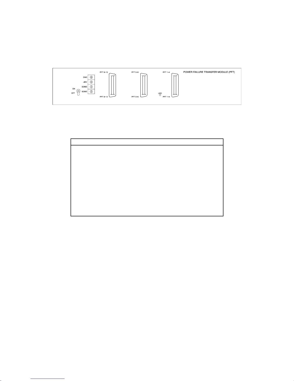
DX-1S DIGITAL PABX - Installation Manual
5.14INSTALL POWER FAILURE TRANSFER MODULE
5.14.1CONNECTORS IN POWER FAILURE TRANSFER MODULE
The module includes three 36 Way Centronic Socket Connectors, one 4 Way Terminal Block and a Power
Switch and Power LED on the panel :
Figure 5-5.9 DX-1S POWER FAILURE TRANSFER MODULE PANEL
The connectors in the rear panel are for the external cables connection as following :
Connector Type Function
Power Input
Terminal
4 Way Terminal Block For -48V Power Supply &
Surge Ground connection
Power Supply Toggle Switch For power input control
Power On LED Green Round LED For Power ON indication
PFT Line
Connector PFT
1~4
36 Way Centronic Socket
Connector
For trunk lines, extension
lines and telephones
connection
PFT Line
Connector PFT
5~8
36 Way Centronic Socket
Connector
For trunk lines, extension
lines and telephones
connection
PFT Line
Connector PFT
9~12
36 Way Centronic Socket
Connector
For trunk lines, extension
lines and telephones
connection
Table 5-21 POWER FAILURE TRANSFER MODULE PANEL CONNECTORS
26
Page 63
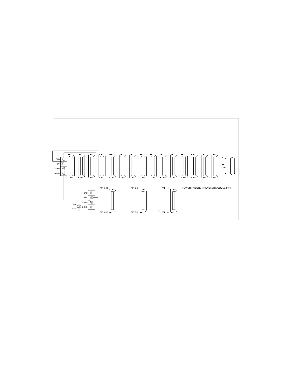
DX-1S DIGITAL PABX - Installation Manual
5.14.2INSTALL POWER FAILURE TRANSFER MODULE IN MODULE SYSTEM CABINET
Unpack the packing of the module.
There is no jumper or Dip Switch setting in module.
Remove the Lower Rear Panel.
Install the Power Failure Transfer Module in the position of Lower Rear Panel.
5.14.3CONNECT POWER CABLE FOR POWER FAILURE TRANSFER MODULE
Connect Pin 4 - SGND (Surge Ground) of Power Failure Transfer Module to Pin 3 - SGND (Surge
Ground) of Module System Cabinet with minimum #26 AWG insulated green wire.
Connect Pin 1 - GND (Battery Ground) of Power Failure Transfer Module to Pin 1 - GND (Battery
Ground) of Module System Cabinet with minimum #26 AWG insulated black wire.
Connect Pin 2 - -48V of Power Failure Transfer Module to Pin 2 - -48V of Module System Cabinet
with minimum #26 AWG insulated yellow wire.
Switch the Power Switch of Power Failure Transfer Module to ON position.
Figure 5-5.10 POWER FAILURE TRANSFER MODULE INSTALLATION
27
Page 64
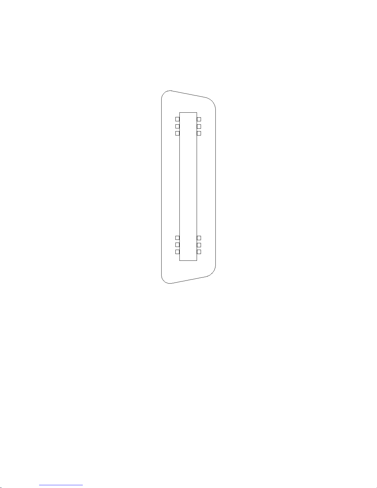
DX-1S DIGITAL PABX - Installation Manual
5.14.4CONNECT PFT LINE CONNECTOR CABLES FOR POWER FAILURE TRANSFER MODULE
Connect the 32-core cables from PFT 1~4 Connector of Power Failure Transfer Module to MDF.
Connect the 32-core cables from PFT 5~8 Connector of Power Failure Transfer Module to MDF.
Connect the 32-core cables from PFT 9~12 Connector of Power Failure Transfer Module to MDF.
Connect the wires in MDF reference to PFT Line Connector Pin Assignment table.
19
18
1
36
Figure 5-5.11 PFT LINE CONNECTOR DIAGRAM
28
Page 65

DX-1S DIGITAL PABX - Installation Manual
5.14.5PFT LINE CONNECTOR PIN ASSIGNMENT
Pin PFT 1~4 Pinout PFT 5~8 Pinout PFT 9~12 Pinout
1 1st Trunk Line Tip 5th Trunk Line Tip 9th Trunk Line Tip
19 1st Trunk Line Ring 5th Trunk Line Ring 9th Trunk Line Ring
2 1st Trunk Interface Tip 5th Trunk Interface Tip 9th Trunk Interface Tip
20 1st Trunk Interface Ring 5th Trunk Interface Ring 9th Trunk Interface Ring
3 1st Telephone Tip 5th Telephone Tip 9th Telephone Tip
21 1st Telephone Ring 5th Telephone Ring 9th Telephone Ring
4 1st Extension Tip 5th Extension Tip 9th Extension Tip
22 1st Extension Ring 5th Extension Ring 9th Extension Ring
5 2nd Trunk Line Tip 6th Trunk Line Tip 10th Trunk Line Tip
23 2nd Trunk Line Ring 6th Trunk Line Ring 10th Trunk Line Ring
6 2nd Trunk Interface Tip 6th Trunk Interface Tip 10th Trunk Interface Tip
24 2nd Trunk Interface Ring 6th Trunk Interface Ring 10th Trunk Interface Ring
7 2nd Telephone Tip 6th Telephone Tip 10th Telephone Tip
25 2nd Telephone Ring 6th Telephone Ring 10th Telephone Ring
8 2nd Extension Tip 6th Extension Tip 10th Extension Tip
26 2nd Extension Ring 6th Extension Ring 10th Extension Ring
9 3rd Trunk Line Tip 7th Trunk Line Tip 11th Trunk Line Tip
27 3rd Trunk Line Ring 7th Trunk Line Ring 11th Trunk Line Ring
10 3rd Trunk Interface Tip 7th Trunk Interface Tip 11th Trunk Interface Tip
28 3rd Trunk Interface Ring 7th Trunk Interface Ring 11th Trunk Interface Ring
11 3rd Telephone Tip 7th Telephone Tip 11th Telephone Tip
29 3rd Telephone Ring 7th Telephone Ring 11th Telephone Ring
12 3rd Extension Tip 7th Extension Tip 11th Extension Tip
30 3rd Extension Ring 7th Extension Ring 11th Extension Ring
13 4th Trunk Line Tip 8th Trunk Line Tip 12th Trunk Line Tip
31 4th Trunk Line Ring 8th Trunk Line Ring 12th Trunk Line Ring
14 4th Trunk Interface Tip 8th Trunk Interface Tip 12th Trunk Interface Tip
32 4th Trunk Interface Ring 8th Trunk Interface Ring 12th Trunk Interface Ring
15 4th Telephone Tip 8th Telephone Tip 12th Telephone Tip
33 4th Telephone Ring 8th Telephone Ring 12th Telephone Ring
16 4th Extension Tip 8th Extension Tip 12th Extension Tip
34 4th Extension Ring 8th Extension Ring 12th Extension Ring
17 Not Used Not Used Not Used
35 Not Used Not Used Not Used
18 Not Used Not Used Not Used
36 Not Used Not Used Not Used
Table 5-22 PFT LINE CONNECTOR PIN ASSIGNMENT
29
Page 66

DX-1S DIGITAL PABX - Installation Manual
5.15INSTALL POWER SUPPLY CARD
Unpack the packing of the card.
Check the fuse condition and value. F1 is a 1.5A quick acting fuse. F2 is a 2A quick acting fuse and
F3 is a 0.5A quick acting fuse.
Check the fuses if they are well installed in the fuse sockets.
Install the Power Supply Card to the 17th slot of the Module System Cabinet which is label as PSC.
Check if the card is plugged into the slot connector firmly.
5.16INSTALL MODULE CONTROL CARD
Unpack the packing of the card.
There is no jumper or Dip Switch setting in Module Control Card.
Install the Module Control Card to the first slot of the Module System Cabinet which is label as MCC.
Check if the card is plugged into the slot connector firmly.
5.17INSTALL DISA VOICE CARD
Unpack the packing of the card.
There is no jumper or Dip Switch setting in DISA Voice Card.
Install the first DISA Voice Card to Module Control Card by connecting the CN3 -18 Way Socket
Connectors on DISA Voice Card to the CN3 - 18 Pin Header on Module Control Card as the following
diagram. The first DISA Voice Card is installed in the center position of Module Control Card.
install the two screws to firmly mount DISA Voice Card on Module Control Cards.
Install the second DISA Voice Card (if available) to Module Control Card by connecting the CN3 - 18
Way Socket Connectors on DISA Voice Card to the CN4 - 18 Pin Header on Module Control Card.
install the two screws to firmly mount the second DISA Voice Card on Module Control Cards.
Install the third DISA Voice Card (if available) to Module Control Card by connecting the CN3 -18
Way Socket Connector on DISA Voice Card to the CN5 - 18 Pin Header on Module Control Card.
Install the two screws to firmly mount the third DISA Voice Card on Module Control Cards.
Check if the 18 Way Socket Connectors are connected with the 18 Pin Headers firmly.
30
Page 67
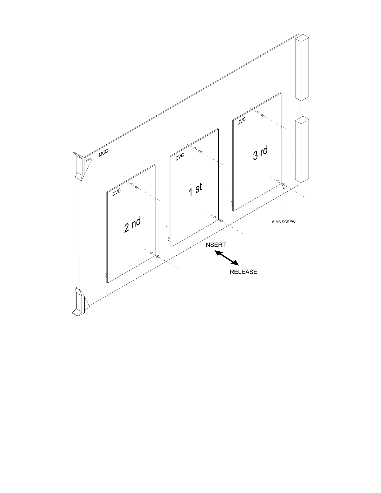
DX-1S DIGITAL PABX - Installation Manual
Figure 5-5.12 DISA VOICE CARD INSTALLATION
31
Page 68
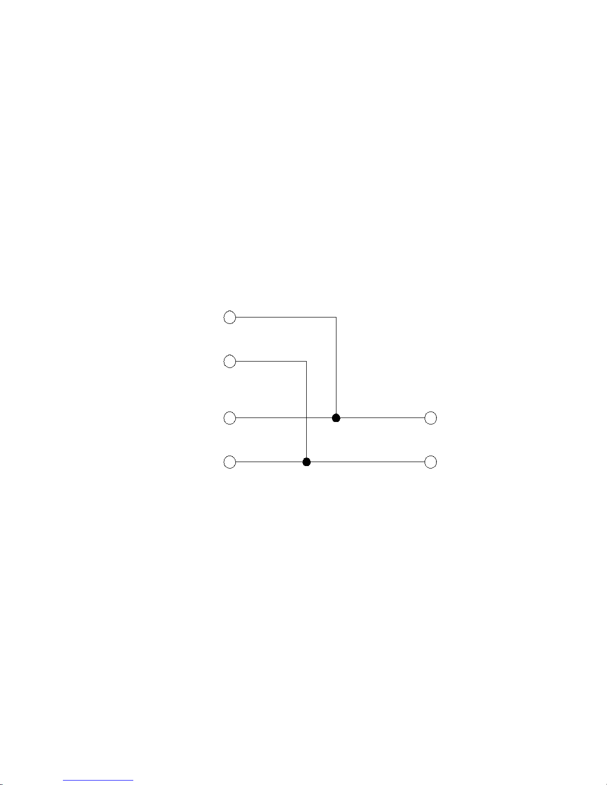
DX-1S DIGITAL PABX - Installation Manual
5.18INSTALL TRK/EXT CARD AND EXT CARD
Unpack the packing of the cards.
There is no jumper or Dip Switch setting in TRK/EXT Card and EXT Card.
Install the first TRK/EXT Card to the 2nd slot of the Module System Cabinet which is label as L01.
Install all the TRK/EXT Cards to the following slots of the Module System Cabinet.
After all TRK/EXT Cards are installed, install the first EXT Card to the slot which is next to the last
TRK/EXT Card.
Install all the EXT Cards to the following slots after the first EXT Card.
Check if the cards are plugged into the slot connectors firmly.
5.19INSTALL CALLER ID CARD
Unpack the packing of the cards.
There is no jumper or DIP Switch setting in Caller ID Card.
Install the Caller ID Card into any free slot from 2 ~ 16 of the Module System Cabinet which are
labeled as L01 ~ L15.
Check if the cards are plugged into the slot connectors firmly.
Connect CIC channel (output at the Line Connectors of Module System Cabinet) to C.O. line. The CIC
channel should connect to C.O. line in parallel with Trunk port (usually connect at MDF).
C.O.
CIC CHANNEL
TRUNK PORT
Figure 5-5.13 CIC CHANNEL CONNECT TO C.O. LINE IN PARALLEL WITH TRUNK PORT
32
Page 69

DX-1S DIGITAL PABX - Installation Manual
Pin EXT Card is installed
1 CIC channel 1 Tip
19 CIC channel 1 Ring
2 Not Used
20 Not Used
3 CIC channel 2 Tip
21 CIC channel 2 Ring
4 Not Used
22 Not Used
5 CIC channel 3 Tip
23 CIC channel 3 Ring
6 Not Used
24 Not Used
7 CIC channel 4 Tip
25 CIC channel 4 Ring
8 Not Used
26 Not Used
9 CIC channel 5 Tip
27 CIC channel 5 Ring
10 Not Used
28 Not Used
11 CIC channel 6 Tip
29 CIC channel 6 Ring
12 Not Used
30 Not Used
13 CIC channel 7 Tip
31 CIC channel 7 Ring
14 Not Used
32 Not Used
15 CIC channel 8 Tip
33 CIC channel 8 Ring
16 Not Used
34 Not Used
17 Not Used
35 Not Used
18 Not Used
36 Not Used
Table 5-23 LINE CONNECTOR PIN ASSIGNMENT OF CALLER ID CARD
33
Page 70

DX-1S DIGITAL PABX - Installation Manual
5.20INSTALL MFC-1S PC INTERFACE CARD
5.20.1INSTALL THE MFC-1S PC INTERFACE CARD IN PC STATION
Unpack the packing of the card.
Inspect all the items are free from damage.
Check correct number of items received.
Prepare a PC station which should meet the following requirements :
Hardware Requirements
PC Computer Station PC/AT Compatible
Processor 386SX 20MHz or higher
Expansion Slot for PC Interface Card
Installation
one XT/AT Slot available
Com Port and Interrupt for PC Interface
Card
Com 4 (2E8) and IRQ 7
RAM 1M Byte RAM
Real Time Clock Built-in with battery backup
Disk Driver 3.5” Floppy Disk Driver
Serial Port (for printer) RS-232C set as COM 1 (3F8) and
operate with IRQ 4
Parallel Port (for printer) Standard Parallel Port set as LPT1
Monitor Hercules monochrome, VGA
monochrome or color monitor
Keyboard w/ Numeric or Standard Keyboard
Table 5-24 PC STATION REQUIREMENTS FOR MFC-1S CONSOLE
Install the MFC-1S PC Interface Card in the XT/AT Slot in the PC station.
Reference to MFC-1S Console for the following installation procedures.
34
Page 71

DX-1S DIGITAL PABX - Installation Manual
5.21INSTALL MFC-1S CONSOLE
5.21.1CONNECTORS IN MFC-1S
There is a power switch in the front panel of PC Computer Station.
The rear panel of PC Computer Station includes the connectors for monitor, keyboard, printer and DX-1S
System connection.
Console-In Connector is for connection with DX-1S System or prior MFC-1S Console. Console-Out
Connector is for next MFC-1S Console connection.
Printer 1 and Com 1 Connectors output the data to for SMDR printing. Printer 1 Connectors is for
connection with parallel port printer and Com 1 Connector is for serial port printer connection.
There are two version of MFC-1S which have the same function but with different type of connectors for
different ports.
The connectors type in Version A and Version B are as following :
Connector Version A Version B Function
AC Inlet 3 Pin AC Power
Male Socket
3 Pin AC Power
Male Socket
For 220V AC Power
connection
AC Outlet 3 Pin AC Power
Female Socket
3 Pin AC Power
Female Socket
For monitor AC
Power connection
Keyboard
Connector
5 Pin Din Socket 5 Pin Din Socket For keyboard
connection
Monitor Connector 15 Way D-Type
(DB-15) Female
Connector
15 Way D-Type
(DB-15) Female
Connector
For VGA monitor
connection
Console-In
Connector
MJ-64 Module
Socket
MJ-64 Module
Socket
For DX-1S or prior
MFC-1S Console
connection
Console-Out
Connector
MJ-64 Module
Socket
MJ-64 Module
Socket
For next MFC-1S
Console connection
Printer 1 Connector 25 Way D-Type
(DB-25) Female
Connector
25 Way D-Type
(DB-25) Female
Connector
For parallel port
printer connection
Com 1 Connector 9 Way D-Type (DB-
9) Male Connector
9 Way D-Type (DB-
9) Male Connector
For serial port
printer connection
Com 2 Connector 25 Way D-Type
(DB-25) Male
Connector
9 Way D-Type (DB-
9) Male Connector
Reserve for future
use
Table 5-25 MFC-1S CONSOLE CONNECTORS
35
Page 72
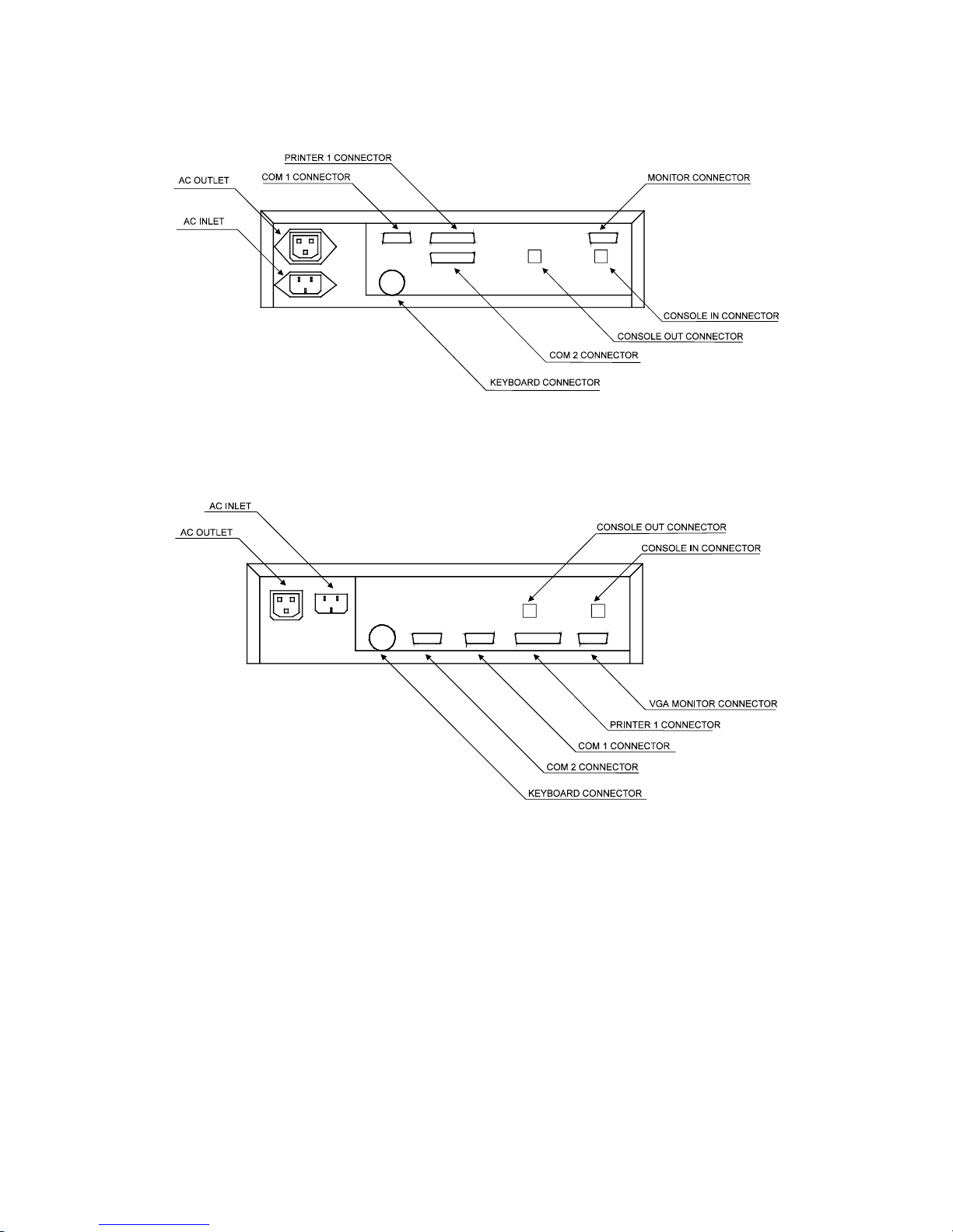
DX-1S DIGITAL PABX - Installation Manual
The rear panel diagrams of Version A and Version B are as following :
Figure 5-5.14 REAR PANEL OF MFC-1S CONSOLE (VERSION A)
Figure 5-5.15 REAR PANEL OF MFC-1S CONSOLE (VERSION B)
36
Page 73
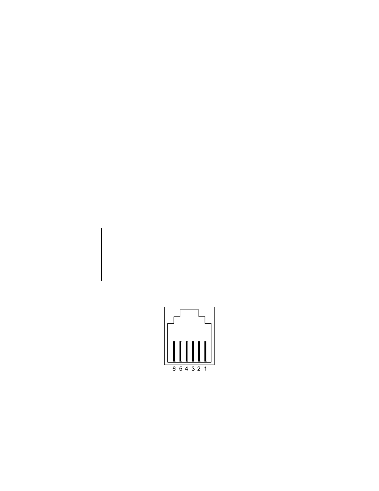
DX-1S DIGITAL PABX - Installation Manual
5.21.2INSTALL THE FIRST MFC-1S CONSOLE
Unpack the packing of the console.
Inspect all the items are free from damage.
Check correct number of items received :
PC Computer Station * 1
9” VGA Monochrome Monitor * 1
Numeric Keyboard * 1
4-Core Cable with RJ-11 Modular Jack * 1
Power Cord * 1
MFC-1S System Software Disk * 1
MFC-1S Reset Disk * 1
Open the cover of PC Computer Station cabinet and check if all the cards is well installed in the mother
board.
Restore the cover to the cabinet.
There are two version of MFC-1S which have the same function but with different type of connectors
for different ports. Please verify the MFC-1S Console is Version A or Version B.
Connect the monitor power cord to the AC Outlet of PC Computer Station.
Connect the monitor signal cable to the Monitor Connector of PC Computer Station.
Connect the power cord to the AC power socket. The power socket must be a 3-wire type with ground
wire connected to the ground of the electrical system.
Connect the 4-core cable from MDF to Connection Box near the Console location.
Connect the 4-core Cable with RJ-11 Module Jack from Connection Box to the Console-In Connector
in the rear panel of the PC Computer Station.
Install a DTMF telephone or headset telephone beside the Console as the console telephone.
Console Connector
in Module System
Cabinet
Console-In Connector
in first MFC-1S
Pin 3 (CTX+) Connect with Pin 4 (CRXIN+)
Pin 4 (CTX-) 4-core Pin 5 (CRXIN-)
Pin 2 (CRX+) cable Pin 2 (CTXOUT+)
Pin 6 (CRX-) Pin 3 (CTXOUT-)
Table 5-26 MODULE SYSTEM CABINET TO 1ST MFC-1S CONSOLE CONNECTION
Figure 5-5.16 CONSOLE-IN AND CONSOLE-OUT (MJ-66) CONNECTOR DIAGRAM
37
Page 74

DX-1S DIGITAL PABX - Installation Manual
5.21.3INSTALL THE SECOND TO SIXTEENTH MFC-1S CONSOLES
Unpack the packing of the console.
Inspect all the items are free from damage.
Check correct number of items received.
Open the cover of PC Computer System cabinet and check if all the cards is well installed in the mother
board. The cards may slip out from the connectors in the mother board during transportation.
Restore the cover to the cabinet.
Connect the monitor power cord to the AC Outlet of PC Computer Station.
Connect the monitor signal cable to the Monitor Connector of PC Computer Station.
The power socket must be a 3-wire type with ground wire connected to the ground of the electrical
system.
Connect the power cord to the AC power socket. The power socket must be a 3-wire type with ground
wire connected to the ground of the electrical system.
Connect the 4-core cable from Console-Out Socket of the first Console to the Console-In Socket of the
second PC Computer Station.
Connect the 4-core cable from the Console-Out Socket of the second Console to the Console-In Socket
of the third PC Computer Station.
Connect all the following consoles with the same method.
Install the DTMF telephones or headset telephones beside the Consoles as the console telephones.
Console-Out
Connector in Prior
MFC-1S Console
Console-In Connector
in Next MFC-1S
Console
Pin 2 (CTXIN+) Connect with Pin 2 (CTXOUT+)
Pin 3 (CTXIN-) 4-core Pin 3 (CTXOUT-)
Pin 4 (CRXOUT-) cable Pin 4 (CRXIN+)
Pin 5 (CRXOUT+) Pin 5 (CRXIN-)
Table 5-27 MFC-1S CONSOLE TO CONSOLE CONNECTION
38
Page 75
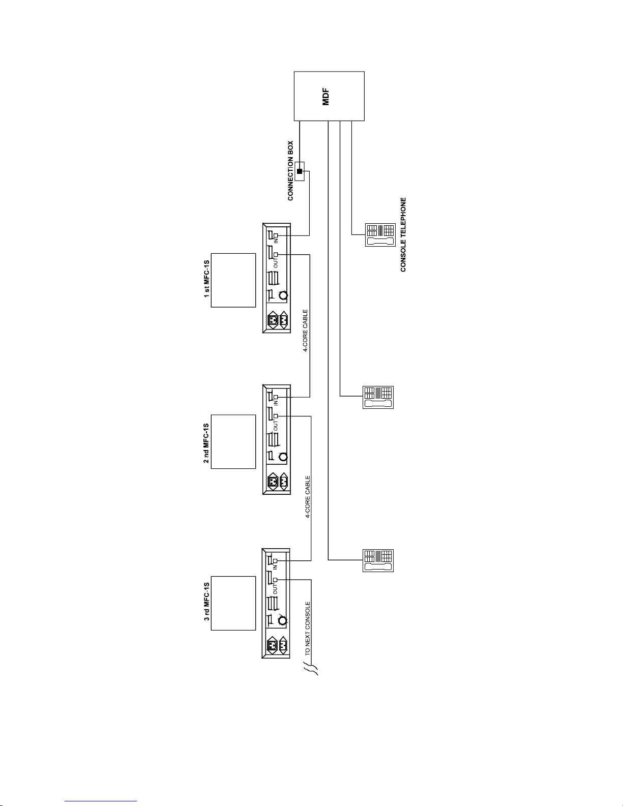
DX-1S DIGITAL PABX - Installation Manual
Figure 5-5.17 MFC-1S CONSOLES CONNECTION DIAGRAM
39
Page 76
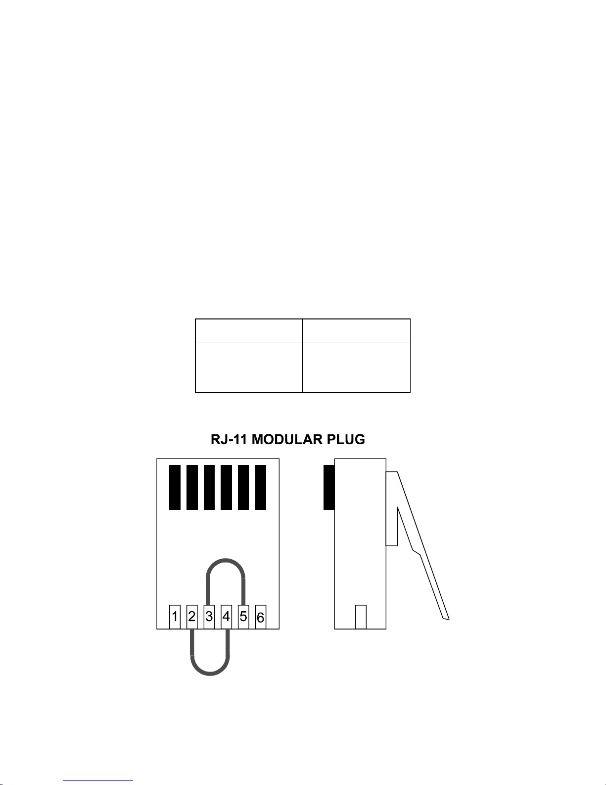
DX-1S DIGITAL PABX - Installation Manual
5.21.4VERIFY THE CONSOLE CABLE LOOP RESISTANCE
The total loop resistance of console cable from Module System Cabinet to the last Console should be
less than 40 ohm.
All consoles must be power down.
Prepare a Console Loop Testing Plug (Reference to Console Loop Testing Plug section).
Install the Console Loop Testing Plug to the Console-Out Socket of the last Console.
Disconnect the console cable from Module System Cabinet Console Connector.
Use a digital multi-meter to measure the resistance between Pin 2 & 3 of the connector of console
cable. The resistance should not be over 40 ohms.
Measure the resistance between Pin 4 & 6 in the connector of console cable. The resistance should not
be over 40 ohms.
If the resistance is over 40 ohms, take action to reduce the resistance : relocate the consoles location in
order to shorten the length of the cable or use a larger diameter conductor cable to be console cable.
After the test, connect the console cable to Console Connector of Module System Cabinet.
Remove the Console Loop Testing Plug in the last Console.
5.21.5CONSOLE LOOP TESTING PLUG
The Console Loop Testing Plug is used to test the loop resistance of the console cable. It is a 6 Pin RJ-
11 Module Plug. Pin 2 and 4 are shorted. Pin 3 and 5 are also shorted. This connector is not included
in MFC-1S Console hardware.
Console Loop
Testing Plug
Connection
Pin 2 short circuit to Pin 4
Pin 3 short circuit to Pin 5
Pin 4 short circuit to Pin 2
Pin 5 short circuit to Pin 3
Table 5-28 CONSOLE LOOP TESTING PLUG PIN ASSIGNMENT
Figure 5-5.18 CONSOLE LOOP TESTING PLUG DIAGRAM
40
Page 77
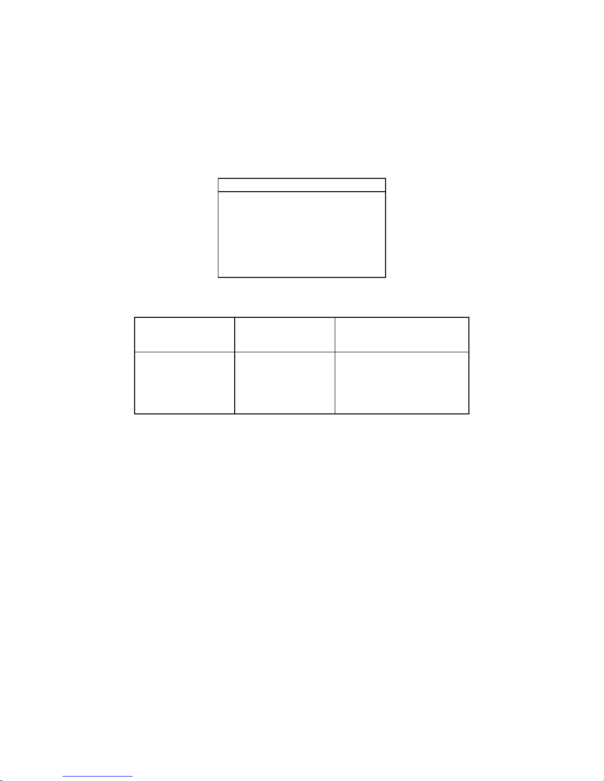
DX-1S DIGITAL PABX - Installation Manual
5.22PRINTER CONNECTION
A parallel printer and a serial printer should be connected to the console if the console need to perform
SMDR, programming data or diagnostic result print out.
For parallel printer, the printer should be PC Compatible parallel printer and connected to Printer 1
Connector. The cable for printer and console connection is the standard parallel printer cable for PC
Compatible computer.
For serial printer, the printer should be connected to Com 1 Connector and configured to meet the serial
port (RS-232C) transmission specification as following :
Serial Printer Port Specification
Serial interface type RS232C
Operating speed 1200 baud
8 data bit
1 stop bit
No parity
Hardware (DTR) Handshaking
Software Handshaking XON/XOFF
Table 5-29 SERIAL PRINTER PORT SPECIFICATION
Com 1 Connector in
Version A (DB-25
Male)
Com 1 Connector in
Version B (DB-9
Male)
Description
Pin 2 Pin 2 Transmitted Data (TXD)
Pin 3 Pin 3 Received Data (RXD)
Pin 6 Pin 6 Data Set Ready (DSR)
Pin 7 Pin 5 Signal Ground
Pin 20 Pin 4 Data Terminal Ready (DTR)
Table 5-30 COM 1 CONNECTOR PIN ASSIGNMENT
5.23EXTERNAL MUSIC SOURCE IMPEDANCE REQUIREMENT
The output specification of the external music source should match the input impedance of External
Music Port.
The input impedance of the External Music Port is 600 ohm and transformer isolated.
No DC current should input to External Music Port.
5.24PAGING SYSTEM OUTPUT IMPEDANCE REQUIREMENT
The input specification of the paging amplifier system should match the output impedance of Page Port.
The output impedance of the Page Port is 600 ohm and transformer isolated.
No DC current should input to Page Port.
41
Page 78
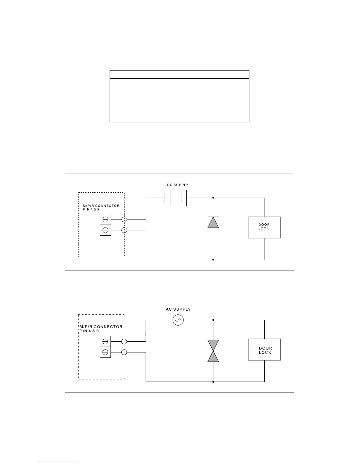
DX-1S DIGITAL PABX - Installation Manual
5.25DOOR LOCK CONNECTION REQUIREMENT
The maximum switching current and voltage for Door Lock Control should not be over the contact rating
as following :
Relay Contact Rating Specification
Relay Contact Normally Open
Relay Time 1 second
Maximum Switching Power 60W, 62.5VA
Maximum Switching Voltage 220V DC, 250V AC
Maximum Switching Current 2A
Maximum Carrying Current 3A
Table 5-31 DOOR LOCK RELAY CONTACT
For door lock purpose, the relay releases the door lock by closing contact. Since the electric door lock is
essentially a solenoid controlled door-strike, there may be some noise and surge generate during the relay
open and close which will cause damage to the PABX system circuit. It is advised to add a diode or
varistor in parallel with the door lock to absorb the surge or noise generated as the following diagram :
Figure 5-5.19 DC DOOR LOCK CONNECTION
Figure 5-5.20 AC DOOR LOCK CONNECTION
42
Page 79

DX-1S DIGITAL PABX - Installation Manual
6.BASIC HARDWARE TEST
6.1CHECKING
The Power Supply SPS-4820 is switched OFF.
The Battery Output Circuit Breaker is switched OFF.
The Power Output Circuit Breaker is switched OFF.
All MFC-1S Console is switched OFF.
Check the cables between Module System Cabinet and SPS-4820 Power Supply are connected
correctly. Wrong connection of these cables will damage the System and Power Supply.
Check the cables between SPS-4820 Power Supply and backup batteries are connected correctly.
Wrong connection of these cables will damage the Power Supply and batteries.
Check all ground cables are well connected.
Check the AC power cord are well installed in AC power socket.
Check all cable connectors are completely plugged into the connectors in Module System Cabinet.
Check all cable connectors are completely plugged into the connectors in Power Failure Transfer
Module.
Check the console cable between MDF and MFC-1S Console is well connected.
Check the console cables between MFC-1S Consoles are well connected.
Check if the DISA Voice Cards are installed in Module Control Card firmly.
Check all cards are plugged into the slot connectors firmly.
6.2POWER ON TEST
Turn on the SPS-4820 Power Supply but not the Battery Output Circuit Breaker and Power Output
Circuit Breaker. You will see the voltmeter in the front panel show that the output voltage is about 53V
after 30 seconds. But there should no output current.
Switch Power Output Circuit Breaker to ON position, the reading of ammeter should be lower than 1A
and indicate that the System is drawing current from SP-4820 Power Supply.
If the System is OK, the Green LED in Power Supply Card will turn on and the Green LED in Module
Control Card will flash.
Switch Battery Output Circuit Breaker to ON position. The output current may increase up to 20A and
the output voltage may drop down a few voltages. It is normal and indicate that the Power Supply is
now charging the batteries if the batteries are not fully charged before. The output current may drop
down after sometimes if the charging process finished.
Perform MFC-1S Console Power On Test.
Perform Power Failure Transfer Module Test.
Perform Extension Functional Test for each extensions.
Perform Trunk Line Functional Test for each trunk.
Perform External Music Port Functional Test.
Perform Paging Port Functional Test.
Perform Door Phone Functional Test.
Perform Door Lock Functional Test.
1
Page 80

DX-1S DIGITAL PABX - Installation Manual
6.3MFC-1S CONSOLE POWER ON TEST
Insert the MFC-1S Software Disk to the floppy disk driver of PC Computer Station.
Turn on the PC Computer Station and Monitor of MFC-1S Console.
The screen should show “Loading MFC-1S Software” message when the console is loading the
program.
The monitor should display the screen of Attendant Console Mode.
The System Status Bar is rotating. If there are TRK/EXT Cards and EXT Cards installed in Module
System Cabinet, the trunk and extension numbers should display on the Attendant Console screen.
If the System Status Bar do not rotate, the console or the system is not yet in normal operation or the
cable between the console and system is not connected.
Start MFC-1S Console Setup Programming. (Reference to MFC-1S Console Operation Manual for
details.)
Start DX-1S System Programming. (Reference to Programming Manual for details.)
6.4POWER FAILURE TRANSFER MODULE TEST
Switch the Power Switch in Power Failure Transfer Module Panel to ON position.
Power On Green LED should light up.
Check in MDF that the trunk lines and trunk interfaces which connected to Power Failure Transfer
Module should be connected to each other.
Check in MDF that the telephone lines and extension interfaces which connected to Power Failure
Transfer Module should be connected to each other.
Switch the Power Switch in Power Failure Transfer Module Panel to OFF position.
The telephone lines are now disconnected with extension interfaces and connected to trunk lines.
The trunk lines are disconnected with trunk interfaces.
If everything OK, switch the Power Switch in Power Failure Transfer Module Panel to ON position.
The Power Switch should remain in ON position for normal operation.
6.5EXTENSION FUNCTIONAL TEST
Pick up the handset of an extension telephone.
Dial to the operator console.
Talk to the operator in order to test the voice circuit.
Ask the operator to dial to the extension.
The extension telephone should ring.
Pick up the handset and talk to operator.
If everything OK, the extension is in normal condition.
Test all the extensions by repeating the testing procedure in each extension telephone.
6.6TRUNK LINE FUNCTIONAL TEST
Pick up the handset of a console telephone.
Dial the specified trunk access code to get a trunk line, you should hear the dialing tone from the trunk
line.
Make an outgoing call and talk to the people.
Ask the outside people to dial to the trunk line.
The assigned trunk answering extension telephone should ring.
Pick up the call and talk to the people.
If everything OK, the trunk is in normal condition.
Repeat the testing procedure to test all the trunks.
2
Page 81

DX-1S DIGITAL PABX - Installation Manual
6.7CALLER ID CARD FUNCTION TEST
Caller ID Card Detection
When DX-1S start, it will display the cards inserted in L01 ~ L15 on the MFC-1S display. Check if
Caller ID Card is correctly detected.
Caller ID Card should have the display: “CIC XX XX XX XX XX XX XX XX”. Where XX is the
version number of each CIC channel. E.g. 03.
Caller ID Transmission Test
Pick up the handset of an extension telephone.
Dial to another extension with a Caller ID telephone connected.
One of the LED on CIC card will turn off which indicate this channel is sending out Caller ID
information.
Check the Caller ID display on the Caller ID telephone – it should show the extension number of
calling extension.
Since system will use the CIC channel one by one, repeat the transmission test 7 times will test all the
CIC channels.
Caller ID Receiving Test
Make sure the trunk lines from C.O. are connected to CIC and the have Caller ID function.
Ask the outside people to dial to the trunk line.
The assigned trunk answering extension telephone should ring and has Caller ID display.
If everything OK, the CIC channel is in normal condition.
Repeat the testing procedure to test all CIC channels.
6.8EXTERNAL MUSIC PORT FUNCTIONAL TEST
Program to enable the External Music feature.
Input music to the External Music Input Port.
Make an intercom call.
Push the Flash key and one of the extensions will be held and hear music.
Adjust the volume of the music source to a suitable level.
6.9PAGING PORT FUNCTIONAL TEST
Program to enable the Paging feature.
Key in Paging Access Code in an extension telephone.
The beep tone is heard and then the telephone is connected to Paging Amplifier System.
Speak some words and your voice will be heard through the Paging Amplifier System.
6.10DOOR PHONE FUNCTIONAL TEST
Test Door Phone if available.
Program to enable the Door Phone feature.
Push the button of the Door Phone, the assigned answering extension telephone will ring.
Pick up the handset and talk to Door phone.
6.11DOOR LOCK FUNCTIONAL TEST
Program to enable the Door Lock feature
Use a digital multimeter to measure the resistance between the two wires of the Relay Contact Port.
Key in Door Lock Access Code in an extension telephone.
The relay contact will become short circuit for one second and then recover to open circuit.
3
Page 82

Page 83
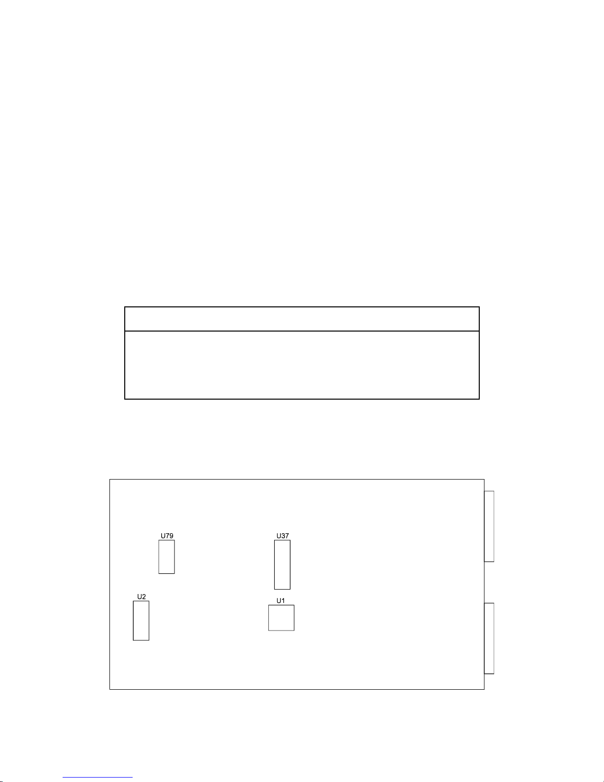
DX-1S DIGITAL PABX - Installation Manual
7.UPGRADE SYSTEM SOFTWARE
7.1DESCRIPTION
The system software will change from time to time to increase the features or improve the performance of
the system. In order to upgrade the system software for existing systems, U2, U37 and U79 integrated
circuits in Module Control Card may need to be rewritten the content with new data or replaced with new
version chips.
Which integrated circuit need to be rewritten or replaced will depend on which part of the software has
been changed. Consult the manufacturer for details.
Important Note : The programming data may be lost after upgrading the software, it is advised to backup
the programming data in hardcopy before changing the software.
7.2BACKUP PROGRAMMING DATA
The programming data may be lost when the system software is upgraded to a higher version. It is very
important to keep a hardcopy of the programming data before upgrading the software. The system should
be re-programmed after changing system software.
7.3INTEGRATED CIRCUITS FOR UPGRADE
The following integrated circuits may need to replaced or be rewritten with new data for system software
upgrade purpose :
Integrated
circuit
Package Description Upgrade method
U2 32 Pin Dip
Package
Contain System
Software
Rewrite the content with
new data
U37 40 Pin Dip
Package
Contain System
Software
Replace with new version
chip
U79 28 Pin Dip
Package
Contain Tone Signal
Information
Rewrite the content with
new data
Table 7-1 INTEGRATED CIRCUIT FOR UPGRADE
These integrated circuits should have labels stuck on the components. The label indicates the version of
software contain in the chip.
The position of the integrated circuits in Module Control Card are shown in the following diagram :
Figure 7-7.1 MODULE CONTROL CARD LAYOUT
1
Page 84

DX-1S DIGITAL PABX - Installation Manual
7.4BASIC PRECAUTIONS FOR UPGRADE
When installing or replacing the Module Control Card to Module System Cabinet, ensure the power has
switched off.
Do not touch the board components or connectors without static-discharge precautions.
Wear anti-static wrist strap when handling the cards.
Handle the cards by the edges and avoid to contact the components and connectors.
The cards should be placed in anti-static package when not in use.
Use IC Extract Tools to take out the integrated circuit from printed circuit board.
A Programmer which is able to program FLASH PROM and EPROM is required.
A EPROM Eraser is required.
7.5REWRITE I.C. U2 FOR SOFTWARE UPGRADE
Take out the integrated circuit U2 from Module Mother Board.
Remove the label on the integrated circuit.
Prepare the new version data file and download to the Programmer which is able to program FLASH
PROM.
Rewrite the content of the integrated circuit with new data by the Programmer.
Stick a new label on the integrated circuit to indicate the version.
Insert U2 in the original IC socket of Module Mother Board.
7.6REPLACE I.C. U37 FOR SOFTWARE UPGRADE
Since U37 cannot be re-programmed, it need to be replaced with new version chip for upgrade purpose.
Take out the integrated circuit from IC socket in Module Mother Board.
Insert a new version chip into the IC socket.
7.7REWRITE I.C. U79 FOR SOFTWARE UPGRADE
Take out the integrated circuit U79 from Module Mother Board.
Remove the label on the integrated circuit.
Erase the content in the integrated circuit with a EPROM Eraser.
Prepare the new version data file and download to a Programmer which is able to program EPROM.
Rewrite the content of the integrated circuit with new data by the Programmer.
Stick a new label on the integrated circuit to indicate the version.
Insert U79 in the original IC socket of Module Mother Board.
7.8POWER ON TEST
Install the Module Control Card in Module System Cabinet.
Switch on the power.
The system should run with the new software.
It may need to initiate the programming data by Software System Initialization or Hardware System
Initialization and re-program the system data again.
2
Page 85

DX-1S DIGITAL PABX - Installation Manual
8.DX-1SU
8.1DESCRIPTION
DX-1SU is a small version of DX-1S, which has maximum capacity of 160 ports. The DX-1SU had
integrated the AC / DC power supply inside the system cabinet, no SPS-4820 or other AC / DC power
supply is required.
The DX-1SU is aimed to provide a cost-effective solution for a system requires less then 160 ports. Since
DX-1SU uses the same software of DX-1S, it includes most of the features of DX-1S.
The main difference between DX-1S and DX-1SU are system cabinet and power supply.
8.2DX-1SU MODULE SYSTEM CABINET
DX-1SU cabinet has the same dimension of the DX-1S cabinet, but the right area inside the cabinet is
reserved for the DX-1SU power supply.
DX-1SU has a smaller Module Mother board, which can accommodate 10 peripheral card at most. So that
it has a maximum capacity of 160 ports per system.
8.3DX-1SU POWER SUPPLY
The DX-1SU Power Supply is a battery backup AC/DC power supply and it should installed in the
dedicated space inside the DX-1SU cabinet. The DX-1SU Power Supply has the function of both AC / DC
power supply and PSC as in DX-1S. The Power Supply inputs 220 AC power, generates DC +5V, -5V,
-48V and Ringing voltage for the System and charges up the backup batteries. Once the AC power is
failed, the Power Supply will switch to the backup batteries automatically and draw the current to the
System without interruption until the AC power is recovered.
8.3.1BUILT-IN INPUT SURGE PROTECTOR
The Power Supply has a Built-in Surge Protector for the AC power input. The surge protector will filters
out the high voltage surge in AC power line and protects the Power Supply from damage.
8.3.2OUTPUT OVER-VOLTAGE PROTECTION
The power supply includes output over-voltage protection. If the 48V output voltage is higher than 60
voltage, the power supply will shut down automatically. It requires manual reset the power supply by turn
off the system, wait about 1 minutes and then turn it on again.
If a backup battery is connected to the Power Supply, the Power Supply will switch to the backup batteries
automatically when the power supply shut down.
8.3.3BATTERY OVER-DISCHARGE PROTECTION
The Power Supply also includes output low-voltage protection to protect the backup batteries from over
discharge. Once the AC power is failed, the Power Supply will switch to the backup batteries automatically
and will draw the current to the System without interruption until the AC power is recovered. The
protection circuit will monitor the output voltage. If the output voltage is under 42V, the protection circuit
will cut off the battery to avoid damaging the batteries. The “L.V.” red LED will light up. If the AC power
recovers and the power supply will charge up the batteries.
8.3.4AUTO-RANGING VOLTAGE
The Power Supply has the Auto-Ranging Voltage capability for input AC voltage. It will accept input
voltage of 85 ~ 132V / 170 ~ 264V.
8.3.5LED INDICATION
The DX-1SU Power Supply has 5 LEDs in the front panel. The first four green LEDs indicate the +5V,
-5V, -48V and Ringing voltage output condition. If the LED turn on, it indicates the output from the Power
Supply is normal.
The fifth red LED is “L.V.” – Low Voltage cut off indication. When it turn on, it indicate the battery output
is under 42V and the batteries are cut off to avoid damaging the batteries.
8.3.6COOLING FAN
The DX-1SU Power Supply has a cooling fan inside for cooling purpose. The cooling fan will turn on
when the Power Supply temperature is high enough (require cooling). When the Power Supply is cooling
down, the fan will turn off automatically.
1
Page 86

DX-1S DIGITAL PABX - Installation Manual
8.3.7SPECIFICATION
Parameter Minimum
Value
Typical Value Maximum Value
AC Input Voltage (110V) 85V AC 110V AC 132V AC
AC Input Voltage (220V) 170V AC 220V AC 264V AC
AC Input Frequency 47Hz 440Hz
Input Overvoltage Protection
Threshold
264V AC
Output Voltage (+5V) 5.1 53.3V DC 5.3
Output Voltage (-5V) 5.1 5.2 5.3
Output Voltage using AC
Input (-48V)
51.5 53.5V DC 55.5
Output Voltage Using
Battery Backup (-48V)
42 48 53
Output Voltage (Ringing) 70 75V AC 80
Max. Output Current (-48V) 4.2A
Battery Undervoltage
Protection Threshold
41.5V DC 42V DC 42.5V DC
Output Overvoltage
Protection Threshold
60V DC
Weight
8.4INSTALLATION
The installation of DX-1SU should follow the precaution and requirement as in DX-1S installation.
Since DX-1SU has a newly design power supply and cabinet, the following section will discuss the
connection of DX-1SU with backup battery and power.
8.4.1CONNECTION OF DX-1SU CABINET, BATTERY AND POWER
Place DX-1SU System Cabinet to the assigned position.
Connect Pin 4 - SGND (Surge Ground) of the Power Output Terminal in DX-1SU System Cabinet to
the System Ground Terminal with minimum #14 AWG insulated green wires.
Connect Pin 1 - Battery + of the Power Output Terminal in DX-1SU System Cabinet to the Positive
Terminal of backup batteries with minimum #14 AWG insulated gray wires.
Connect Pin 2 - Battery - of the Power Output Terminal in DX-1SU System Cabinet to the Negative
Terminal of backup batteries with minimum #14 AWG insulated red wires.
Check all the connections are well connected and low resistance.
The length of the cables between Module System Cabinet, Power Supply and backup batteries should
not be over 2 meters. The over length cables will cause unstable to the system.
Verify Ground Connection (Reference to Verify Ground Connection).
Connect the Power Cord from AC INPUT socket at DX-1SU System Cabinet to the AC Power Socket.
2
Page 87
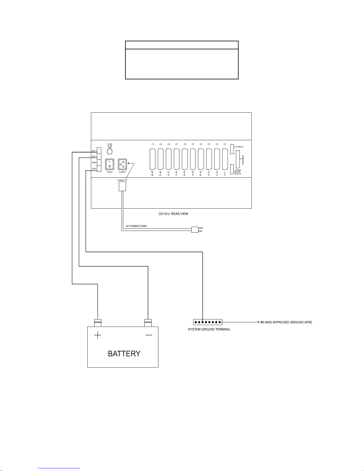
DX-1S DIGITAL PABX - Installation Manual
Power Input Terminal Description
Pin 1 Battery +
Pin 2 Battery Pin 3 Surge Ground
Pin 4 Surge Ground
Table 8-2 DX-1SU SYSTEM CABINET POWER OUTPUT TERMINAL
Figure 8-8.1 DX-1SU SYSTEM CABINET, POWER & BATTERY CONNECTION DIAGRAM
3
 Loading...