

Page 1

Page 2

Dear Customer
We congratulate you for intelligently choosing CEIL Static UPS that incorporates latest DSP
controlled IGBT base technology.
This manual provides you a thorough understanding of your Static UPS and its optimum use.
Please read the installation and operating instructions in this manual carefully before installing
and using your CEIL Static UPS. Pay special attention to the section under PRECAUTIONS. Here
the manual pinpoints conditions or practices which could not only result in damage to your
Static UPS or other equipment but also result in personal injury or loss of life.
Should you need help at any time please feel free to contact us, we would welcome any
queries/suggestions from you that will enable us to improve product quality and also offer you
better service.
With best wishes and warm regards
Management Team
Exide Industries Limited India.
Important Safety Instructions
• Read this manual thoroughly before operation.
• Keep this instruction booklet safe.
• This unit is intended for installation in a temperature controlled, indoor area free from
conductive contaminates.
• Make sure your AC input is properly grounded. Improper grounding might cause hazard
and is against WARRANTY condition.
• While cleaning, do not apply any chemical solvent to the unit. Use dry cloth to avoid
anything dripping into the circuit.
• Keep the unit away from damp areas.
• Do not leave the unit in direct sunlight.
Page 3

Contents
Topic Page no.
Knowing your CEIL DSP Sine wave Static UPS 1
Front Panel 1
Back Panel 2
Display Status 3
Some Safety Measures 4
Concept of Charging 6
Getting Started 7
Installing your Static UPS 8
Operation
Installation Diagram 10
Technical Specifications 11
Troubleshooting 12
Test Report of Static UPS 13
Installation Check List 14
Page 4
Knowing your Static UPS
A static UPS ensures uninterrupted power supply to large electrical loads of commercial and
residential establishments during power outage. In its most basic form, a Static UPS transforms
Alternating Current (AC) to Direct Current (DC) for providing the required charging current for
the Battery Bank connected with it and also, to convert Direct Current (DC) of the Battery Bank
to Alternating Current (AC) for the electrical loads. The Battery Bank with the Static UPS acts as
a reservoir to ensure continuous supply of power whenever mains supply from utility power is
not available.
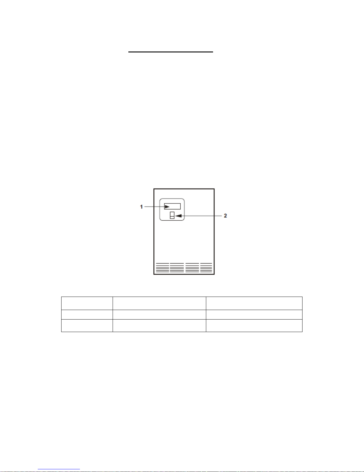
Front Panel:
Front Panel Diagram
Position No. Function Remarks
1 LCD Display all parameter
2 ON/OFF ON/OFF Switch
Status: Battery Voltage, Output Voltage, battery Charging and charged, Output Load in Static
Inverter Mode and Mains Voltage.
Page 5
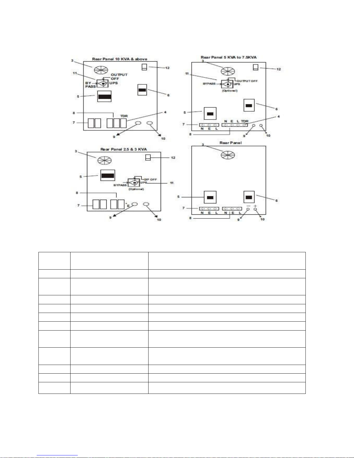
REAR Panel
Position
No.
3 Fan For cooling the Unit
4 Inbuilt time Delay To run compressor load like A.C.Time delay relay
5 AC Mains MCB To switch on the AC main (Utility Power)
6 Battery MCB To switch on the DC supply
7 AC Mains For AC mains connection
8 Output For output load connection
9 Battery Terminal
Negative (Black)
10 Battery Terminal Positive
(Red)
11 BYPASS switch In case of system failure to BYPASS the system
12 Inverter/UPS To toggle the system in Inverter or UPS mode
Function Remarks
(TDR) has been provided.
To connect battery wire black
To connect battery wire red
Page 6

Display Status
Status On Display Alarm
IUPS I/P……………………..Volt No
running on mains O/P…………………… Volt
I/P Freq……………..Hz
O/P Freq…………… Hz
Battery Charging
Battery ………………Volt
Mains OK
Load……………………%
Battery Low Protection Battery Low Beeping
Output over load Warning Beeping
Overload
I/P MCB Trip I/P MCB Trip Beeping
O/P Short Circuit Protection Short Circuit Beeping
UPS on Battery Mains not OK Beeping Every 5 Min.
I/P……………………..Volt
O/P…………………… Volt
I/P Freq……………..Hz
O/P Freq…………… Hz
Load %
Over Temp. Protection Over Temp. Yes
Page 7

SOME SAFETY MEASURES
Important Precautions:
CEIL DSP Sine wave Static USP has two Battery terminals coming out from the rear side, an AC
MCB, a DC MCB, an AC output socket and an AC Input socket. Battery terminals are red and
black in colour. The red colour terminal has to be connected to the POSITIVE TERMINAL of the
battery and black one to the NEGATIVE TERMINAL.
CAUTION:
Do not reverse the battery connections as it will trip the Battery MCB/ Fuse.
Ensure that the incoming phase (or line) is connected to 'L', Neutral is connected to 'N' and
earth is connected through OUTPUT socket of the Static UPS.
General Precautions:
Before using the CEIL DSP Sine wave Static UPS read all instructions and caution
markings on the Static UPS, the batteries and all appropriate sections of this Instruction
manual.
Do not expose CEIL DSP Sine wave Static UPS to any type of chemicals.
Do not disassemble the CEIL DSP Sine wave Static UPS. Take it to a qualified our
Engineering Service Centre when service or repair is required. Opening by unqualified
person can lead to electrical shock or fire hazard.
To reduce risks of electric shock disconnect all wiring before cleaning.
WARNING:
Avoid exposing the Static UPS or Batteries to any type of explosive gases in the vicinity as
batteries generate explosive gases during normal operation. Ensure proper ventilation for the
battery compartments. The Battery enclosures should be so designed as to prevent
accumulation and concentration of hydrogen gas in 'pockets' at the top of the compartment.
Vent the battery compartment from the highest point. A sloped lid can also be used to direct
the flow to the vent opening location. To reduce the risk of battery explosion, strictly follow the
instructions of the battery supplier for any equipment you intend to use in the vicinity of
batteries.
Use the correct tools to make AC/DC wiring connections.
Do not install this CEIL DSP Sine wave Static UPS on or near flammable materials
(plywood, chemicals, gasoline etc)
Page 8

CAUTION:
The CEIL DSP Sine wave Static UPS should be connected to grounded, permanent wiring
systems.
Personal Precautions:
A person should be within the range of your voice so as to come to your aid when you
work near batteries
Keep plenty of fresh water and soap nearby in the event that battery acid comes in
contact with skin, clothing or eyes.
Avoid touching eyes while working near batteries; Wash your hands when work done.
If battery acid comes in contact with skin or clothing wash immediately with soap and
water. If acid enters eyes immediately flood eyes with running cool water for at least 15
minutes and get medical attention immediately.
Baking soda neutralizes battery electrolyte.
NEVER smoke or allow spark or a flame in the vicinity of the battery.
Be extra cautious when working with metal tools on and around batteries. It could
short-circuit the batteries or other electrical parts, producing a spark that could cause
an explosion.
Remove personal metal items such as rings, bracelets, necklace and watches when
working with the battery. Battery can produce short-circuit current high enough to
cause severe burns.
Never attempt to charge a frozen battery.
Before touching the Battery terminal makes sure that the Static UPS front switch is OFF
and AC mains to the Static UPS is also OFF.
If it is necessary to remove any battery, always remove the grounded terminal from the
battery first. Make sure all the accessories are off, so as not to cause arcing.
Be sure that the area around the battery is well ventilated.
Clean battery terminals. Be careful not to allow corrosion to come in contact with eyes.
Study specific precautions and recommended rates of charge of all battery
manufacturers.
Add only distilled water in each cell until battery acid reaches level specified by battery
manufacturer. This helps purge excessive gas from cells. Do not overfill. For a battery
without caps, carefully follow manufacturer's recharging instructions.
Exide India, is not responsible for any kind of battery related problems.
Page 9

CONCEPT OF CHARGING
Five Stage Pulse Charging
Bulk:
Batteries are charged at maximum allowed continuous constant charging current at constant
voltage for speedy charging of battery up to 13.8V (for a 12V battery).
Boost:
The charger checks the charging current when the battery voltage reaches 13.6V for 12V
batteries. The boost mode of the charger will be activated, which will boost the battery up to
20% more than its rated voltage (14.4V for 12V batteries) and charging current is reduced to
50% of bulk charging rate (i.e. 4 to 5AMP).
Taper:
When the voltage level of battery is 20% more than its rated voltage, the taper mode of the
charger will be activated, which will keep the charging current at about 4AMP to achieve the
specific gravity of electrolyte for fully charged battery.
Float:
In float stage the charger keeps the charging voltage& current level at its trickle charging set
point of 13.6 V with minimum charging current at 1.0 AMP.
Pulse (Reset):
To maintain the float level, the charger resets to zero current at 13.6V for some time and starts
again with pulse charging of <1 AMP current at same voltage. This keeps the battery in full
charge condition even when not in use.
Page 10

GETTING STARTED
THICKNESS
Environment
Static UPS / Inverters are sophisticated devices and must be treated accordingly. Keep the Static
UPS in a non-condensing, well-ventilated environment, ensuring there is no ingress of moisture
or foreign material.
Location
Static UPS should be kept as close as possible to the battery in order to keep the battery cables
short. However do not locate the Static UPS in the same compartment as non-sealed batteries
since the gas from battery generator gases is very corrosive and can damage electronic
equipment and other items.
Important Precaution
The output side of the Static UPS AC wiring should never be connected to a generator or
incoming utility power. This condition is far worse than a short circuit. If the unit survives this
condition, it will shut down until correction is made.
An independent circuit breaker (MCB/MCCB) is suggested for INPUT & OUTPUT according to
the CEIL Static UPS capacity.
For Input, Output, battery wire thickness refers to table below.
I/P WIRE O/P WIRE BATTERY
THICKNESS THICKNESS WIRE
UPS (KVA)
(sq. mm) (sq. mm)
(sq. mm)
2.5 KVA-36/48 VOLT 2.5 2.5 10
3 KVA-36/48 VOLT 2.5 2.5 16
5 KVA-48/96/120/180 VOLT 6 6 10
7.5 KVA-120/180 VOLT 10 10 16
10 KVA-180/192 VOLT 10 10 10
12 KVA-192 VOLT 16 16 16
Page 11

INSTALLING YOUR STATIC UPS
Mounting
Mounting the Static UPS in a ventilated enclosure with sealed batteries is acceptable. Avoid
mounting the Static UPS in a closed container. To operate at high power for sustained periods
of time unrestricted airflow is required. Without the protection, circuitry will activate and
reduce the maximum power available or cause complete shutdown of the Static UPS. As per
standards, Static UPS should be mounted on a flat surface.
NOTE:
Never disconnect the battery cables while the Static UPS is delivering power or battery charger
is operating. The ON/OFF switch has no effect on the charger; it only turns OFF the Static UPS.
To disconnect the batteries for servicing:
a) Turn OFF the power switch.
b) Disconnect all AC power.
c) Disconnect all the battery cables
DC CABLING
Ensure that the ON/OFF switch on the front panel of the Static UPS is in the OFF Position
before you begin the installation; also keep DC MCB and AC MAINS MCB in OFF position.
Connect the positive terminal of the battery bank to the positive (Red) terminal of the
Static UPS.
Connect the negative terminal of the battery bank to the negative (Black) terminal of
the Static UPS.
Ensure that the battery wires and interconnects are of proper rating. It is advised to use
50amp or above rated wire.
AC CABLING
Connect AC input supply to the input mains terminal of the Static UPS so that the phase
is connected to (L), neutral is connected to (N) and earth is connected to (E).
Connect output wires to the output terminals of the Static UPS so that the phase is
connected to (L), neutral is connected to (N) and earth is connected to (E).
Use proper rated wire for input & output AC connector.
Page 12

AIR CONDITIONER WIRING
The air-conditioner requires a 5 minute delay each time the supply is interrupted. To provide
for the time delay, a socket (TDR) is provided at the back panel of Static UPS.
WARM UP
Secure all the wiring with ties or other non-conductive fasteners to prevent damage.
Switch on DC MCB. Check the front LCD panel.
Switch on the front panel switch and verify the Static UPS operation.
Switch on AC MCB and give AC mains to the Static UPS. In Static UPS of 10KVA & above,
the LCD display will get ON just after connecting the battery bank with OUT switch on
the battery MCB.
OPERATION
Once the AC and DC wiring have been installed and connected, take a moment to re-examine
all the connections and make sure they are secured and in the proper terminals.
Check to see that the Static UPS is turned off, and then apply battery (DC) power to it. Ensure
that all wiring has been installed properly. Next turn on the battery bank DC disconnects or
connects the proper fuse/MCB in line to the battery to complete the battery circuit.
Put ON/OFF switch to the ON position. The Static UPS should run a load without AC mains input
(battery only). Place a load on the Static UPS and make sure it works.
To charge your batteries, connect AC mains to the Static UPS by plugging in the AC power and
turning on the AC mains line. This shows that charger is working properly. Any AC load powered
by the Static UPS should also work at this point since the AC mains passes through the Static
UPS to power the loads.
Disconnect the AC mains. The Static UPS should transfer to Battery mode immediately. The
Static UPS will begin to take power from the batteries and use it to power the load and the load
continues to operate uninterrupted.
The above steps will complete a functional test of the Static UPS. If all areas pass, the Static
UPS is ready for use. If areas fail, figure out why before proceeding.
Page 13
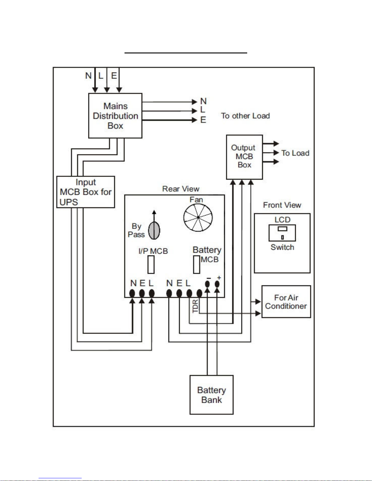
Installation Diagram For Static UPS
Page 14
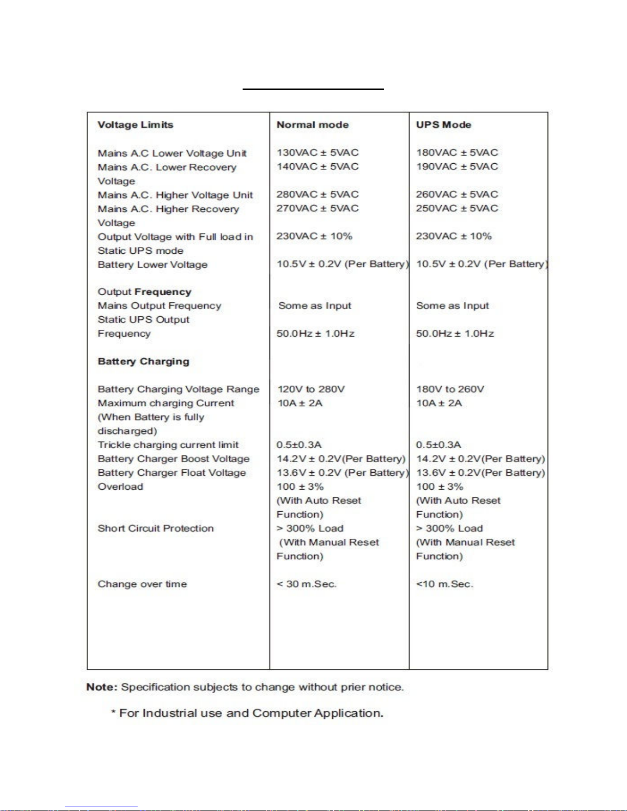
Technical Specifications
Page 15
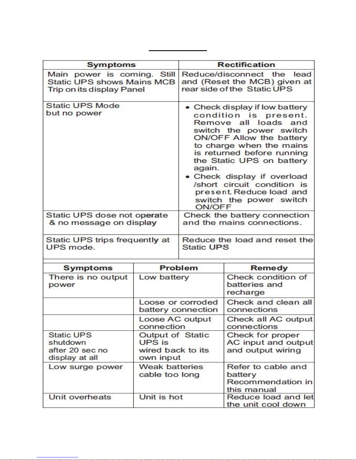
Trouble Shooting
Page 16
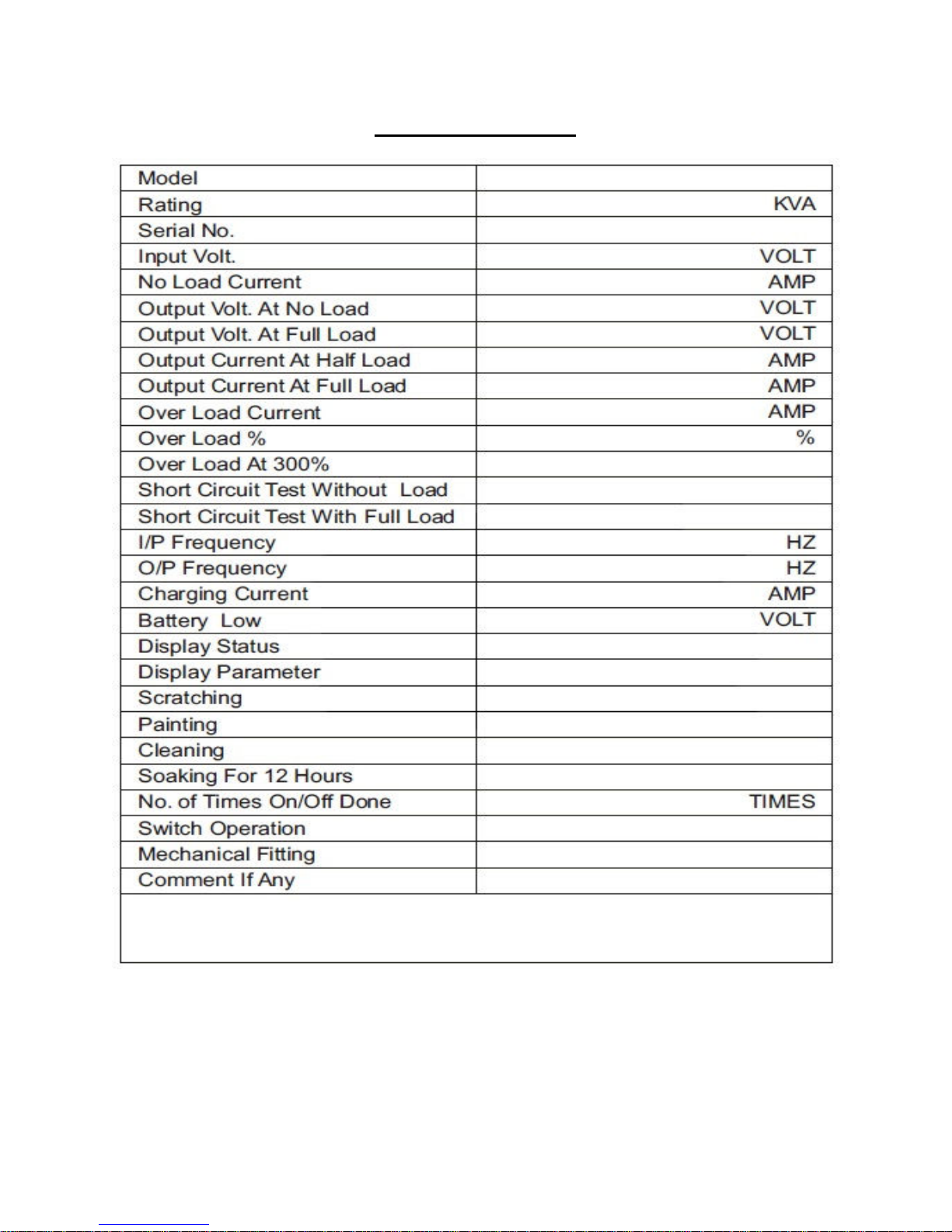
Static UPS Test Report
Tested by …………………………………………………… Inspected by………………………………………………
Date…………………………………………………………… Date…………………………………………………………..
Sign……………………………………………………………. Sign…………………………………………………………….
Page 17

Installation Check List
Environment
Remarks
Place
Noise
Y/N
Dust
Y/N
Without Cooling
Y/N
With Cooling
Y/N
Ventilat
ion Y/N
Distance Between UPS and Walls
METER
Mains Side
Rating of I/P Circuit Breaker
AMP
I/P Wire Thickness
sq. mm.
Back Up System Capacity (DG Set
KVA
Mains Stabilizer capacity and
KVA
No. of Earthing Pit
Mains Voltage
Mains N
-
E Voltage
Mains Frequency
Output Side
Rating of Output Circuit Breaker
AMP
O/P Wire Thickness
sq. mm.
Outp
ut Voltage
Volts
Output N
-
E Voltage
Volts
Output Frequency
Hz
Output Load
Battery
Distance Between Battery Pack and
Battery Wire Thickness
sq. mm.
Tightness O
f Battery Wire in UPS
Battery Inter connectors wire
Earthing
Earth for Chasis
Earth for Neutral
Capacity and Make)
make (if any)
1Ph./3Ph
1Ph./3Ph
Back Up System (DG Set)Frequency Hz
UPS
Battery Capacity/Make/Type/MFD
Date
METER
side and Battery side
thickness and tightness
Customer’s Sign ………………………………………… Engineer’s Sign………………………………………….
Name………………………………………………………… Name………………………………………………………..
Date………………………………………………………….. Date………………………………………………………….
Page 18

Customer Awareness Static UPS /Inverter
Technology use : DSP Sinewave
Capacity of Inverter : ……………..VA
No. of Battery use/DC voltage : ………..Nos / ……………Volt DC
Input Voltage range : (120V-280V) in normal mode
(180V-260V) in UPS mode
Output voltage : 230 Volt AC
Output current at full load : ……………….AMP
Output frequency : 50HZ+/- 1.0% (stable)
Output wave form : Sinewave
Static UPS front panel : ON/Off switch and LCD display
Rear panel : Mains MCB, Battery MCB, Bypass & switch, I/P Terminal
Block
& O/P Terminal Block Battery Connections
Battery Care : Please check the water level in the battery once in two
months.
Make sure Battery terminal should be clean.
Customer’s Sign ………………………………………… Engineer’s Sign………………………………………….
Name………………………………………………………… Name………………………………………………………..
Page 19

 Loading...