

Page 1
FI002K0021v1100UK – THS/21E and THS/21 Programming Manual
Industrial Metal Detectors
THS/21E & THS/21
Programming Manual
Document code Date Software version
FI002K0021v1100UK 20/12/2011 THSV5401 – ALMV5400
Read this Manual carefully before installing, operating or carrying out maintenance on the device. Keep the Manual in a safe
place for future reference, and in perfect condition. This Manual must accompany the device described therein in the
case of change of ownership, and until the device is broken up.
1
Page 2
FI002K0021v1100UK – THS/21E and THS/21 Programming Manual
SYMBOLS
The equipment is marked with this symbol wherever the user should refer to this Manual in order to avoid possible
damage. The same symbol appears in the Manual at points where warnings or particularly important instructions,
essential for safe, correct operation of the device, are given.
The equipment is marked with this symbol in the areas where there is dangerous voltage. Only trained maintenance
personnel should carry out work in these areas. The same symbol appears in the Manual at points where warnings
essential for safe, are given.
This symbol appears in the Manual at points where suggestions, additional information or other relevant notes are given.
REVISION RECORD
Revision Date Author Reference Description
1000 09/11/2010 TP2 – SP - First Emission – Upgrading FI025GB2K8v6
1001 06/04/2011 TP2 – SP - Web server, Bin lock, USB management
1100 07/10/2011 TP2 – SP - Upgrade to THSV5401
2
Page 3

CONTENTS
FI002K0021v1100UK – THS/21E and THS/21 Programming Manual
1 SAFETY INSTRUCTIONS – WARNINGS ....... 5
1.1 General warnings ...................................... 5
1.2 Correct use of the device .......................... 5
2 PROGRAMMING ............................................. 6
2.1 Access to Programming ............................ 6
2.1.1 Factory preset configuration ....................... 6
2.1.1.1 Access levels ..................................... 6
2.1.1.2 Remote Communication ..................... 7
2.2 Administrator functions ............................. 7
2.3 Configuration of the system by the
Administrator ............................................. 7
2.3.1 Programming .............................................. 7
2.3.2 Users .......................................................... 7
2.4 General points on programming ............... 8
2.4.1 Keypad functions ........................................ 8
2.4.2 Entering the username ............................... 9
2.4.3 Entering the password .............................. 10
2.4.4 Restricted login ......................................... 10
2.5 Exit from programming ........................... 11
2.5.1 Exit from programming ............................. 11
2.5.2 Time out ................................................... 11
2.6 Defining a new user ................................ 11
2.7 Quick Access menu programming
procedure ................................................ 12
2.8 Programming the Metal Detector
according to the kind of product .............. 13
2.8.1 Procedure for minimizing the "product
effect" ....................................................... 13
2.8.2 Procedure for automatic product
acquisition ................................................ 13
3
3 PROGRAMMING PARAMETERS ................. 15
3.1 Administrator .......................................... 15
3.1.1 Remote passwords .................................. 16
3.2 Reset ...................................................... 17
3.3 Product selection .................................... 17
3.4 Products .................................................. 18
3.4.1 Save prod.to USB .................................... 20
3.4.2 Load prd. from USB ................................. 22
3.5 Autolearn ................................................ 24
3.6 Autolearn-advanc ................................... 25
3.7 Detection ................................................. 26
3.8 Ejection ................................................... 28
3.9 Counters ................................................. 32
3.10 Configuration .......................................... 33
3.10.1 Compatibility chk ...................................... 33
3.11 Configuration-adv ................................... 37
3.11.1 Network config. ........................................ 40
3.11.2 Motor config ............................................. 50
3.12 Barcode reader ....................................... 53
3.13 I/O Status ................................................ 55
3.13.1 Outputs .................................................... 55
3.13.2 Inputs ....................................................... 55
3.13.3 Measures ................................................. 56
3.13.4 Variables .................................................. 56
3.14 Diagnosis managem. .............................. 57
3.15 MD Test .................................................. 63
3.16 Fail-safe test ........................................... 63
3.17 Print ........................................................ 64
3.17.1 With no IXC card installed ........................ 64
3.17.2 With IXC card installed ............................. 65
3.17.2.1 Save events ..................................... 66
3.18 Q-C setup (Quality Control) .................... 68
3.19 Test samples .......................................... 70
3.20 Unlock bin ............................................... 70
3.21 Commands accessible only in Remote
Programming .......................................... 71
3.22 Remote programming ............................. 76
3.22.1 Communication parameter settings ......... 76
3.22.1.1 RS232 or RS232 Aux ...................... 76
3.22.1.2 Bluetooth ......................................... 76
3.22.1.3 Ethernet / WiFi connections (only
with IXC card) .................................. 76
3.22.2 Entering remote programming ................. 77
3.22.2.1 Connecting to a Metal Detector ....... 77
3.22.2.2 Displaying a parameter setting ........ 77
3.22.2.3 Changing a parameter setting ......... 77
3.22.2.4 Executing a function ........................ 77
Page 4

FI002K0021v1100UK – THS/21E and THS/21 Programming Manual
3.23 Access via Web Server ........................... 78
3.23.1 Network configuration .............................. 78
3.23.2 Functions available .................................. 78
3.23.2.1 Status .............................................. 79
3.23.2.2 Products .......................................... 79
3.23.2.3 Products Counters ........................... 80
3.23.2.4 Test Diameters ................................ 80
3.23.2.5 Products Export ............................... 81
3.23.2.6 Products Import ............................... 81
3.23.2.7 Products Delete ............................... 82
3.23.2.8 Buffers Export .................................. 82
3.23.2.9 Configuration Backup/Restore ......... 83
3.23.2.10Configuration Export/Import ............. 84
3.23.2.11Network ........................................... 85
3.23.2.12System upgrade (Web Server) ........ 86
3.23.2.13Maintenance .................................... 86
3.23.2.14System Info ...................................... 87
3.23.2.15Logout .............................................. 87
4 APPENDIX ..................................................... 89
4.1 Parameters list – Alphabetical order ....... 89
4.2 Parameters list – Menu order ................. 90
4
Page 5

Read this Manual carefully before installing or operating the device and before carrying out maintenance operations.
FI002K0021v1100UK – THS/21E and THS/21 Programming Manual
SAFETY INSTRUCTIONS - WARNINGS
1 SAFETY INSTRUCTIONS – WARNINGS
1.1 General warnings
- All personnel operating on the device must have an adequate preparation and shall know the
procedures described in this Manual.
- Observe current regulations regarding electrical and personal safety for both the operator
and the installer when installing the device.
- Any modificat ion to the system is forbidden and void all warranties and certifications.
- Follow the instructions contained in this Manual for all operations relating to installation, use
and maintenance of the device.
CEIA cannot be held responsible for any damage resulting from procedures which are not
expressly indicated in this Manual, or from any lack of attention, either partial or total, of the
procedures described therein.
- This Manual must accompany the device described therein in the case of change of
ownership, and until the device is broken up.
1.2 Correct use of the device
1
- The Metal Detectors from the
detection of metal masses transiting inside the detection antenna.
- The final user is responsible for selecting the appropriate sensitivity for their application.
After this selection has been made, and programming has been adjusted ac cordingly, it is
also the final user's responsibility to verify calibration using the test object(s) appropriate to
the level of security selected. Additionally, this test should be carried out periodically to
insure no changes have occurred in the equipment.
THS/21E
and
THS/21 series
are electronic devices for the
5
Page 6
FI002K0021v1100UK – THS/21E and THS/21 Programming Manual
2
PROGRAMMING
2 PROGRAMMING
The list of parameters and menus, accessible by each users, together with the system behaviors, can change in respect
of this Manual description, depending on the settings modifications. Contact the System Administrator for any
information.
2.1 Access to Programming
Upon access to Programming a user name and a password are requested.
Each type of operator can access a specific set of parameters, consisting of one or more menus.
2.1.1 Factory preset configuration
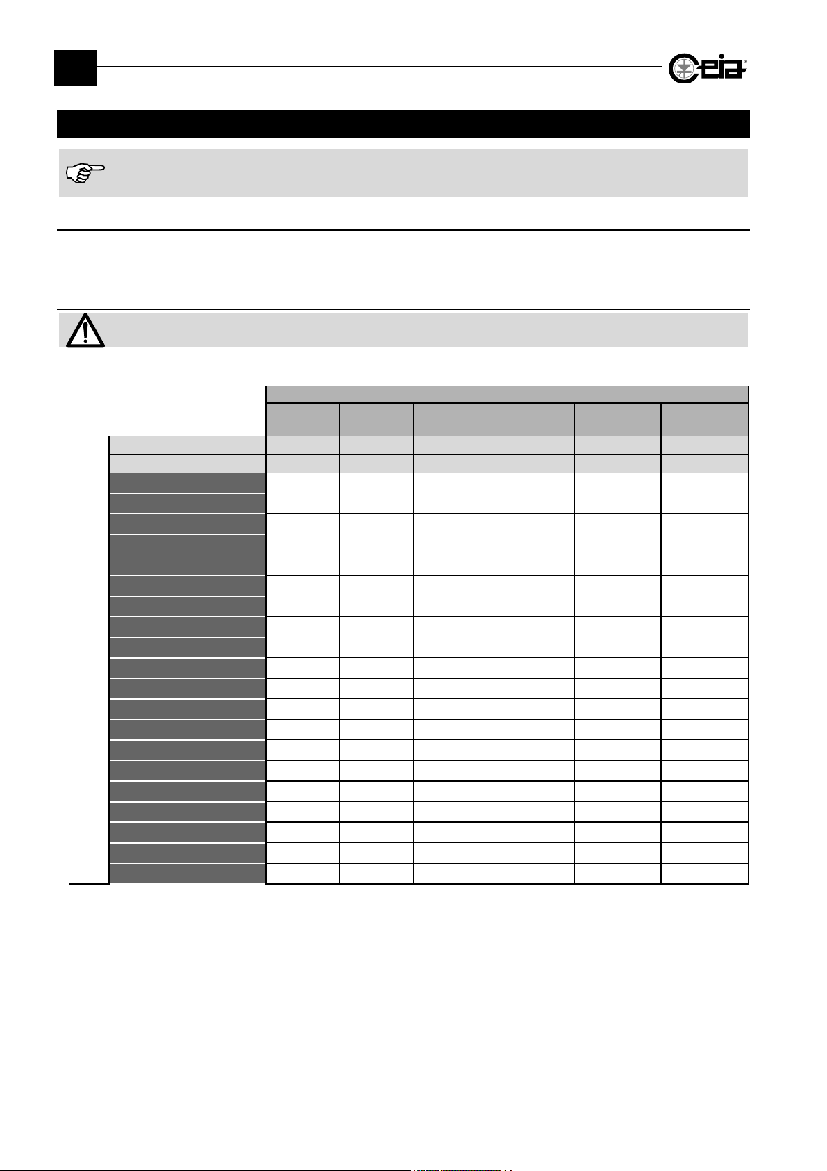
When first switched on, the Metal Detector is configured with predefined users with access parameters as described in
the following table:
2.1.1.1 Access levels
Administrator
Reset
Product Selection
Products
Autolearn
Autolearn-advanc
Detection
Ejection
Counters
Configuration
Configuration-adv
MENU
Barcode reader1
I/O Status
Diagnosis managem.
MD Test
Fail-Safe test 2
Print
Q-C setup
Test samples
Unlock bin
1 – The Barcode reader menu is available only upon request
2 – The Fail-safe Test menu is available only with an Ejection confirmation sensor installed
Username
Password
Operator Supervisor Technician
000001 000002 000003 000004 000005 ADMINI
000001 000002 000003 000004 000005 000000
• • •
•
• •
• •
•
• •
• •
• •
•
•
• •
• •
•
Predefined operators
Quality Control
Operator
Head of
Quality Control
Administrator
• •
•
•
•
•
•
•
•
•
• • •
• •
•
•
• • •
• •
6
Page 7
2.1.1.2 Remote Communication
For the Remote Communication, two access type are provided:
- Only the password (predefined password is 000006). This access type is selected by default.
- User and Password exactly as a local access (see table above).
To select which access type to use, see parameters RM and AURM.
Only the Administrator operator can manage all the users.
It is Administrator responsibility to redefine all predefined access data in order to avoid unauthorized access to
programming.
2.2 Administrator functions
The Administrator has total control over the configuration of the Metal Detector and can define the
roles of the staff that will be working with it. The Administrator's prerogatives, therefore, are the
following:
- Modifying or deleting existing operators and/or setting new passwords.
- Defining new operators and their password s.
- Authorization for operators to access operational parameters, grouped into menus.
- Total access to all operating parameters.
FI002K0021v1100UK – THS/21E and THS/21 Programming Manual
PROGRAMMING
2
2.3 Configuration of the system by the Administrator
2.3.1 Programming
The Administrator can program the detector independently to define its operational configuration, or
can delegate one or more functions to the operators.
2.3.2 Users
The Administrator defines the users that work with the detector according to their respective
responsibilities. The Administrator therefore gives the user:
- an user name and a password for access to Programming
- the indication of the operational parameters that the user can modify or display.
The Administrator can define up to 40 users (including the Administrator).
It is imperative that the Administrator responsible for the device redefines the users and passwords pre-set in the factory
in order to block access to Programming on the part of unauthorized personnel.
It is not possible to modify the username ADMINI.
THS/21 is the first system on the market that allows complete personalization of product names and of the users that work
with them (name and surname, user name, password, …).
7
Page 8
FI002K0021v1100UK – THS/21E and THS/21 Programming Manual
2
PROGRAMMING
2.4 General points on programming
2.4.1 Keypad functions
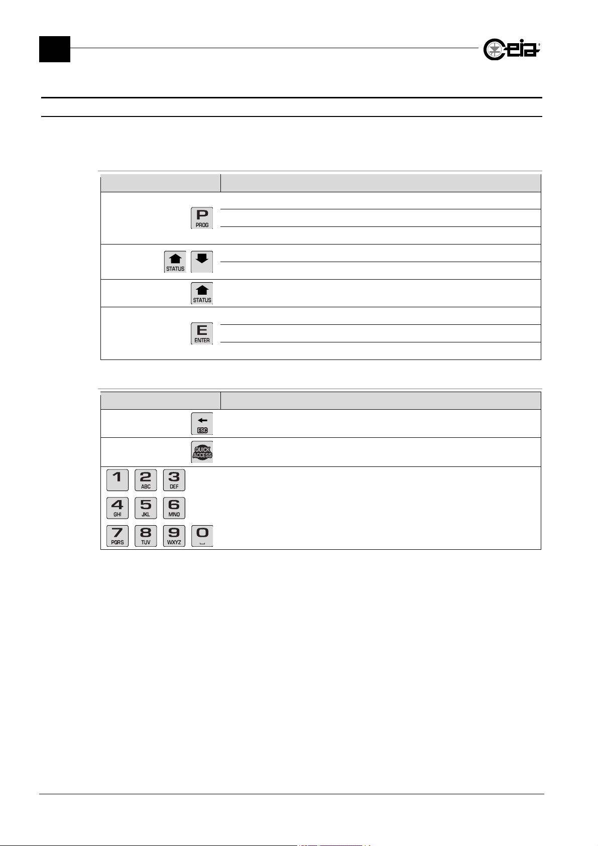
The control of the Metal Detector and the setting of the device parameters are performed through
the control panel keyboard, as shown below:
On THS/xx21 and THS/xx21E
Key Function
Access and exit from the programming phase
Return back from the submenus to the previous menu
Exit from the Metal Detector Status visualization
Scroll through the sequence of instructions
Choice of the parameters to be changed
Metal Detector Status visualization
Selection of the selected submenu from the main menu
Confirmation of the data entered
Reset of some kinds of fault
Only on THS/xx21
Key Function
Cancel the last character entered
Quick access to predefined functions, with programming method complying with
CFR21 (see User Manual)
Modification of the parameter values
8
Page 9
2.4.2 Entering the username
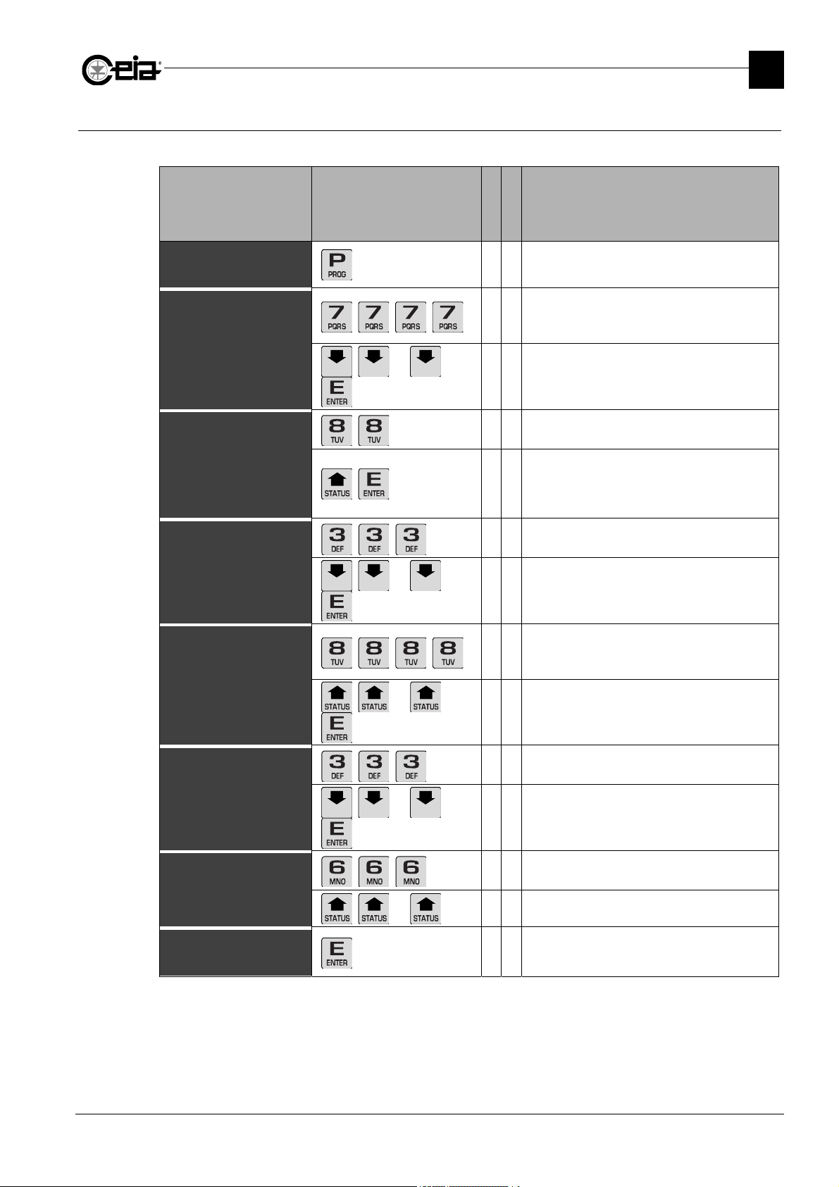
In the following example, the way to digit the username “STEVEN” is shown.
FI002K0021v1100UK – THS/21E and THS/21 Programming Manual
PROGRAMMING
2
Display Keys pressed
User
#_____
User
S#____
User
ST#___
User
STE#__
…
…
Meaning
THS/21
THS/21E
Press P to enter Programming. The cursor
• •
blinks in the position of the first character
Press four times the key “7” to cycle through
the letters and to set the “S” as the first
•
character. The cursor moves automatically on.
Press 8 times the DOWN arrow to cycle back
the alphabet and select the letter “S” as the
•
first character. Press E to confirm.
Press twice the key “8” to set the “T” as the
•
second character.
The cursor moves on and starts suggesting
again the last character entered. Press once
•
the UP arrow to select the letter “T” and press
E to confirm.
Press three times the key “3” to set the “E” as
•
the third character.
Using the DOWN arrow key, cycle back the
alphabet until the letter “E” is shown. E to
•
confirm.
User
STEV#_
User
STEVE#
User
STEVEN
User
STEVEN
…
…
…
•
•
•
• •
Press four times the key “4” to cycle through
the letters and to set the “V” as the fourth
character.
Using the UP arrow key, cycle up the alphabet
•
until the letter “V” is shown. E to confirm.
Again three times the key “3” to set the “E” as
the fifth character.
Using the DOWN arrow key, cycle back the
alphabet until the letter “E” is shown. E to
•
confirm.
Press three times the “6” to set the “N” as the
last character.
Using the UP arrow key, cycle up the alphabet
•
until the letter “N” is shown.
Press “Enter” to confirm the username
9
Page 10
FI002K0021v1100UK – THS/21E and THS/21 Programming Manual
LOGIN RESTRICTED
2
PROGRAMMING
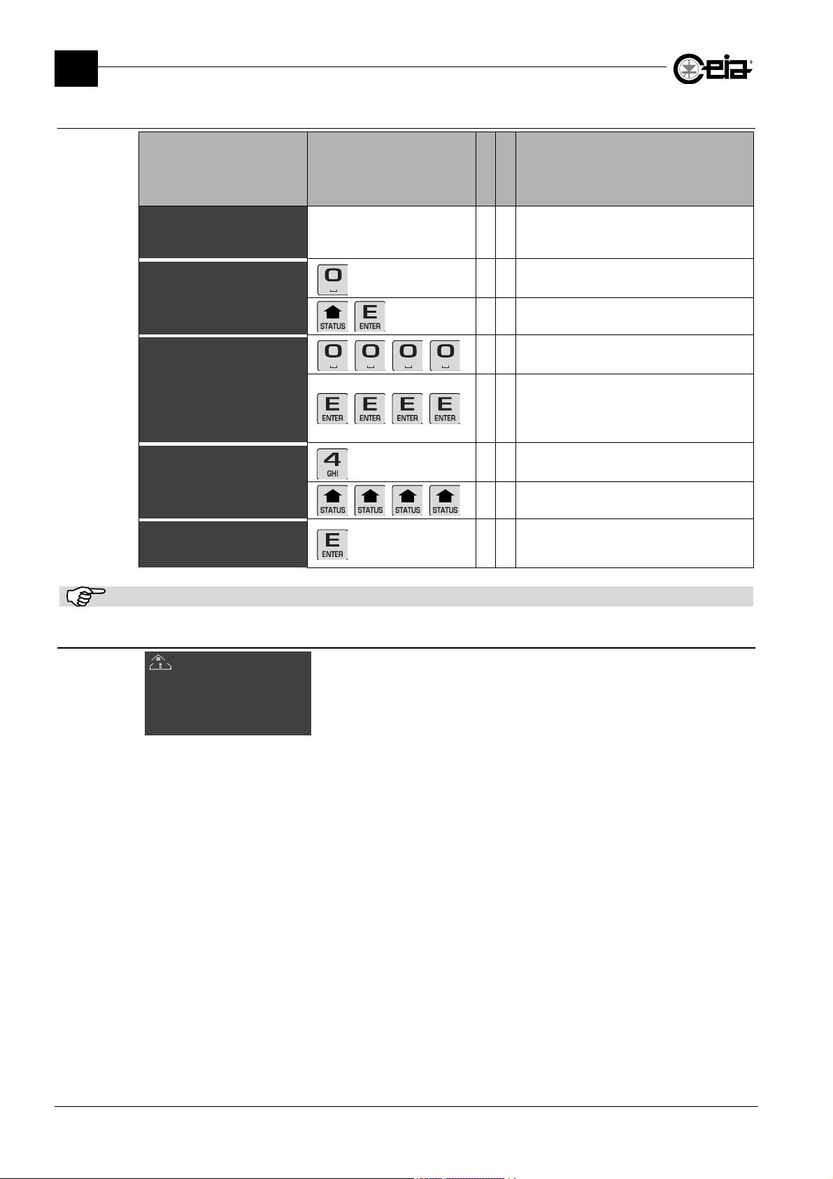
2.4.3 Entering the password
Display Keys pressed
Password
#_____
Password
*#____
Password
*****#
Password
******
Password
******
The display will show an asterisk in the place of each character entered.
2.4.4 Restricted login
To reset from this fault, enter Programming at Administrator level and exit. In case the
Administrator lost the password to login, contact CEIA.
Meaning
THS/21
THS/21E
After the user name, the password is
This fault message appears if three consecutive attempts to access
with the wrong password or user name have been made (see
parameter FLR).
Due to this event, the detector is NOT operative and set itself on fault
status.
required. As an example we will digit
• •
“000004”.
Push “0” to get for the letter “0” as the first
•
character. The cursor moves on.
Push the UP arrow key to select the “0” as
•
the first character. E to confirm.
Continue to push “0” until the cursor reach
•
the last character position.
The cursor moves on and starts suggesting
again the last character entered. Continue
•
to push E until the cursor reach the last
character position.
Press once the key “4” to set the number
•
“4” as the last character
Press four times the UP arrow key to set
•
the number “4” as the last character
Press “Enter” to confirm the password
• •
10
Page 11
Administrat
Administrat
C
C
\
\\ C
\\\
]
U
OPER01
U
OPER01
N
JOHN
U
OPER01
P
U
OPER01
C
C
2.5 Exit from programming
2.5.1 Exit from programming
Press the P key to exit from the current menu (or submenu), until the main screenshot is
shown on the display.
2.5.2 Time out
The programming session will be terminated automatically if no commands are entered for a period
of 5 minutes.
2.6 Defining a new user
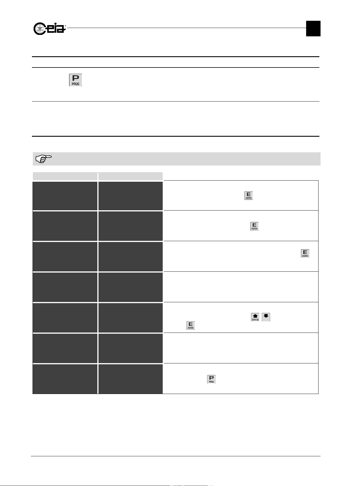
Example: John Smith, product operator, password OPER01, enabled for Product sele ction me nu.
Before creating a new user, or assigning a new operator to a pre-defined one, print the event list and erase the event
buffer.
THS/xx21E THS/xx21
or §
Reset
Product selection
Products
reate user @
Modify user
Erase user
Remote passwords
Reset
Product selection
Products
Autolearn
Autolearn-advanc
Detection
Ejection
reate~user~~~~~~~~~§
Modify user
Erase user
Set BlueTooth PIN
Remote passwords
or~~~~~~~§
FI002K0021v1100UK – THS/21E and THS/21 Programming Manual
PROGRAMMING
Select menu Administrator, pressing .
Select command Create user, pressing .
2
==== Create user ===
#_____
--------------------
ser
Name USER01
Surname USER01
Descrip. USER01
ame
Surname SMITH
Descrip OP PROD
Password OP0001@
assword
Reset N
Product selection Y@
Products N
reate user @
Modify user
Erase user
Remote passwords
@
[
#_____
{|||||||||||||||||||}
Name USER01
Surname USER01
Descrip. USER01
Password
Reset N
Product selection N
Products N
Name JOHN
Surname SMITH
Descrip. OP PROD
Password~~~~~~OP0001@
Reset N
Product selection N
Products N
Name JOHN
Surname SMITH
Descrip. OP PROD
Password OP0001
Reset N
Product~selection~~Y@
Products N
Modify user
Erase user
Set BlueTooth PIN
Remote passwords
reate user
ser~~~~~~~~~~
ser
ser
reate~user~~~~~~~~~§
@
Enter name of new user (6 alphanumeric characters) and press to
confirm.
The properties list will appear, followed by the menu list.
Enter the name, surname, a brief description and the desired
password, by scrolling using the arrows and selecting by
pressing .
Enable the Product selection menu only by changing the menu status
from N (disabled) to Y (enabled).
Exit the menu with to confirm the newly-defined user.
11
Page 12
FI002K0021v1100UK – THS/21E and THS/21 Programming Manual
Administrat
Administrat
C
Autol
[\\
\ QUICK ACCESS
\
]
[\\
\ QUICK ACCESS
\
]
[\\
\ CREATE LINK
\
\\\
]
CEIA THS/PH21N
[\\
\ QUICK ACCESS
\
]
2
PROGRAMMING
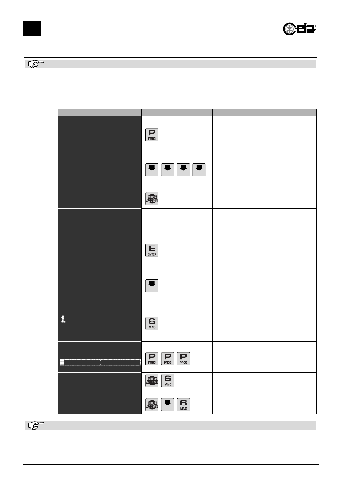
2.7 Quick Access menu programming procedure
This function is not available on THS/21E models.
The system Administrator can program up to 10 shortcuts to menus or single parameters, in order
to quickly activate them through the Quick Access and the correspondent numeric key (0-9).
Here below, as an example, we will program the Autolearn menu to the position 6 of the Quick
Access list.
Display Keys pressed Meaning
Reset
Product selection
Products
Autolearn
Autolearn-advance
Detection
Ejection
Reset
Product selection
Products
Autolearn~~~~~~~~~~~~§
Autolearn-advance
Detection
Ejection
reate~link~to~~~~~~~@
Erase link
Erase all links
Erase link
Erase all links
0) Products
1)
2) Sensitivy
3)
4) Reset
& Scroll down
{||||||||||||||||||||}
$ Scroll up
5)+MD Test
6)
7)+Print
8)+I/O Status
9)+Counters
{||||||||||||||||||||}
[\\\\\\\\\\\\\\\\\\\\]
{||||||||||||||||||||}
{||||||||||||||||||||}
earn~~~~~~~~~~~~@
Link 6
created
or~~~~~~~~§
or
\\
\\
Access to the parameters list.
Select command or parameter to be added in
the Quick Access function list.
Press the Quick Access key and hold it
pressed until the display will change as
shown.
The first line will alternatively show the
message Create link to and the name of the
selecterd function/parameter.
Press E to accept. The display will show the
Quick Access list, in order to assign the right
number.
In the example beside, the number 1 and 3
are free to be used.
Press the down arrow to scroll the Quick
Access list to the second page.
Press 6 to choose that position in the list.
12
ALM V5.xxx THS V5.xxx
Product:PROD01
$ Scroll up
5)+MD Test
6)+Autolearn
7)+Print
8)+I/O Status
9)+Counters
{||||||||||||||||||||}
\\
Press three times P to exito from
or
Programming
Now the Quick Access + 6 will call for the
Autolearn menu (a menu is indicated, in the
list, with a + in front of the name)
The parameter/menu called with Quick Access will request the insertion of an username and/or a password, if needed.
Page 13
FI002K0021v1100UK – THS/21E and THS/21 Programming Manual
Prod
SUGAR01
Autol
OFF
Autol
OFF
Autol
OFF
Autol
OFF
Autol
Autol
PROGRAMMING
2.8 Programming the Metal Detector according to the kind of product
The operating mode of the Metal Detector is to be determined according to the kind of product to
be inspected, in order to obtain:
- the minimization of the ”product effect” (see below);
- the determination of the detectable metallic Test Samples (see below);
- a correct ejection mode configuration according to the product (see also Installation Manual);
The factory settings (product DEFAULT) are suitable for dry products.
It is always advisable to optimise installation in line with the criteria described in the installation Manual in order to obtain
maximum sensitivity and maximum rejection of environmental interference.
2.8.1 Procedure for minimizing the "product effect"
The goal of this procedure is to obtain the following operating mode:
a) the detector does not set off an alarm when some of the pure product, without any metallic
contamination, passes through the probe.
b) the detector sets off an alarm when some of the product containing a metallic sample passes
through the probe
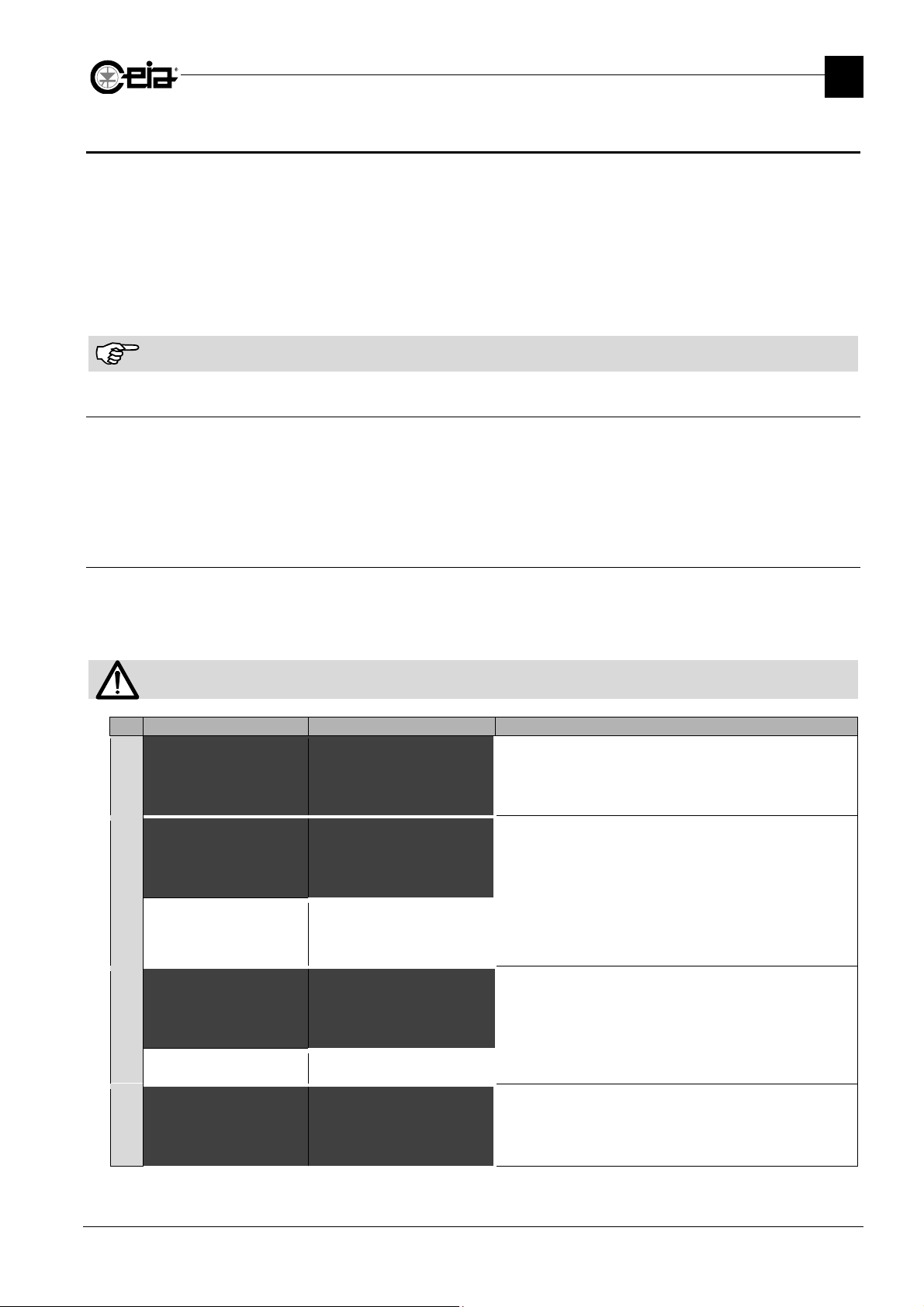
2.8.2 Procedure for automatic product acquisition
This procedure comprises the automatic acquisition of non-contaminated product cha racteristics in
order to identify the contribution to the received signal due to the metal mass to be detected. The
characteristics are acquired progressively by making the product pass through the Metal Detector
several times.
2
The procedure must be completed once started. Do not change any parameter setting during the procedure.
# Display THS/xx21E Display THS/xx21 Step
=== New product ===
1
BISC#________
-------------------
earn
Multi-band ON@
Min.trans.number 1
2
.
Rename product
[\\ New product \\\]
BISC#_______
{||||||||||||||||||}
earn
Aut.det.mode~sel~~ON@
Min.trans.number 1
Select a product or create a new one (see User Manual, par.
3.6.1).
On THS/xx21 set Autolearn > Aut.det.mode sel to ON to
perform an autolearn for all detection modes. Set it to OFF to
perform it only on the current detection mode. Set it to ON if
not sure about the correct detection mode of the product.
On THS/21E-3F set Autolearn > Multi-band to ON to
perform an autolearn for all bands. Set it to OFF to perform it
only on the current band. Set it to ON if not sure about the
correct band of the product.
earn
Multi-band ON
Min.trans.number 1@
3
earn ON@
Multi-band ON
4
Min.trans.number 1
earn
Aut.det.mode sel ON
Min.trans.number~~~1@
earn~~~~~~~~~ON@
Aut.det.mode sel ON
Min.trans.number 1
Set the parameter Autolearn > Min.trans.number to a
suitable value for the product composition. The value of 1 is
suggested for products that have regular shape and
composition, higher the product non-uniformity, higher should
be the minimum transits to perform a correct autolearn
Set Autolearn > Autolearn to ON and exit from the
programming phase (push P button).
13
Page 14
FI002K0021v1100UK – THS/21E and THS/21 Programming Manual
PASS PRODUCT
PROCESS
WAIT
THS/21E V5.3
CEIA THS/21
STATUS
\\\\\\]
2
PROGRAMMING
# Display THS/xx21E Display THS/xx21 Step
Prod. PROD1
5
^
^^^^^^^^^^---65%
6
^
Prod. PROD1
7
^
xx
PASS PRODUCT
Product:PROD01
process ...... 65%
Product:PROD01
ALM V5.xxx THS V5.xxx
Product:PROD01
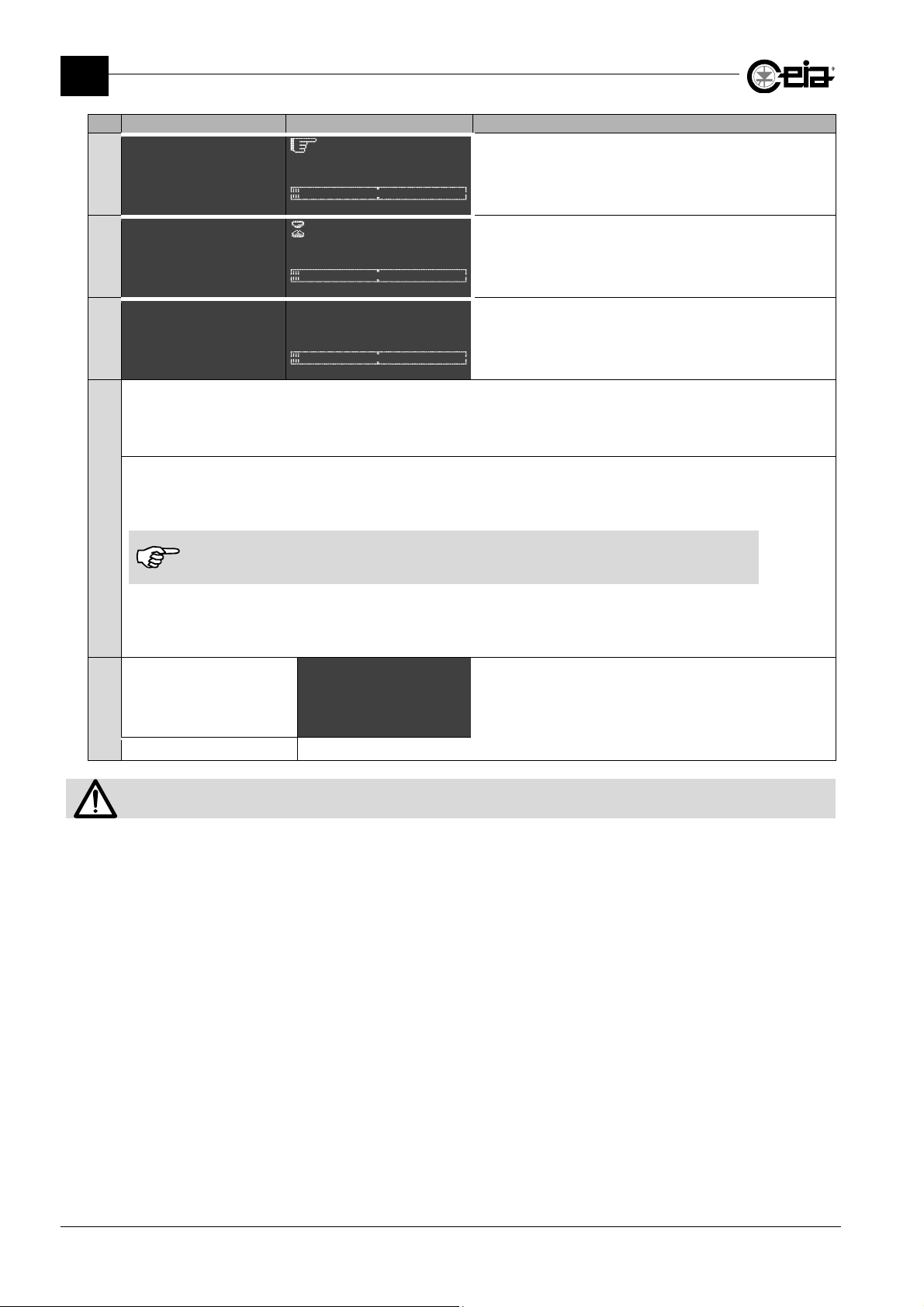
Pass some pure product through the detector: the device should not set off any alarm. If the detector gives an alarm
whenever some of the pure product passes through the probe, repeat the procedure, increasing the number of transits (see
8
point 3.). At the end of this second procedure, the pure product is still giving alarm, decrease the “Sensitivity” parameter
until the detector does not give an alarm (this is probably due to non-uniformity of the product).
Pass some of the product with the metallic sample: the detector should give an alarm. If any alarm is given,
increase the size of the metallic sample gradually, until locating its minimum dimension that will be detected with at least 5 dB,
in order to ensure the detection of the sample in every transit position.
In the case that the size of the metallic samples has been modified, communicate them
9
immediately to the Head of Quality Control or to the Administrator, so as to let them to change
their values in the relative menu.
If the signal given by the sample is higher than 12 dB, the Metal Detector Tests can fail. See SAC parameter.
It is responsibility of the customer to determine the diameter values of the test samples to be used in the Quality Control
Procedure. It is responsibility of the Quality Control Head to set this values on the MD Test Samples menu.
[\\\\\
Sensitivity 265
Not available
-
on TH/21E
Detection mode 4
FE perform. 0.80
NFE perform. 1.00
SS perform 1.20
Prd. alarms 10
{|| & Scroll down ||}
Pass the non-contaminated product through the Metal
Detector each time is requested. The message PASS
PRODUCT appears on the display, and the buzzer (if
enabled) is activated.
At the end of each transit, the Metal Detector will ask to wait
for a few seconds, in order to process the signal. In this
phase, the alarm led is blinking.
At the end of the Autolearn procedure, the Metal Detector
exits from the autolearn phase and the standard message
appears on the display.
At the end of the procedure, on the Metal Detector Status
screen, will be indicated the minimum detectable diameters.
This indication is purely indicative and it is responsibility of
the customer to verify their effective detection.
The minimum detected diameters can be different from the indication on Status screen.
14
Page 15
FI002K0021v1100UK – THS/21E and THS/21 Programming Manual
Administrat
C
U
OPER01
U
OPER01
3 PROGRAMMING PARAMETERS
PROGRAMMING PARAMETERS
3
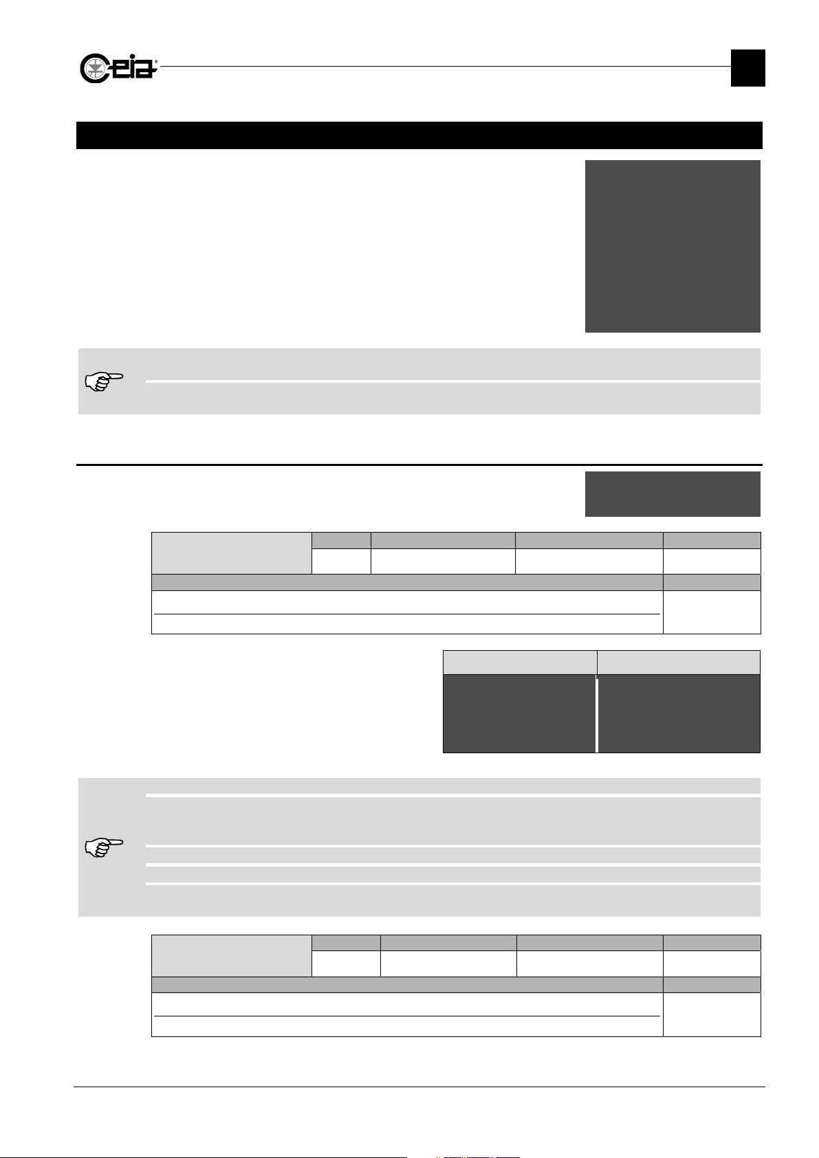
After user logging, the list of available Local Programming Menus is
shown. The list changes according to the permission levels of the
user logged. The list beside is the example of the programming tree
for the Administrator level.
Each parameter or command is described in detail, together with
corresponding Remote Programming code (if available); moreover,
the type (global or related to the current Product) and the Models that
include it in the Programming, are reported.
Some parameters require the use of Input Devices and/or Relays. Therefore, the settings of these parameters have
effect only on Metal Detectors that have Input lines and Relays involved (See Installation Manual).
The parameter standard settings can change according to the Metal Detector System. For each Metal Detector unit, they
are reported on the Factory Acceptance Test Sheet attached to the Installation and Maintenance Manual.
3.1 Administrator
List of commands available under the Administrator menu
Create User
Description Models
Creation of a new user
Enter the name of a new user: a list of the user's properties will appear.
-
Name from 1 to 12 alphanumeric char.
-
Surname from 1 to 12 alphanumeric char,
-
Description from 1 to 12 alphanumeric char,
-
Password 6 alphanumeric characters
-
List of menus that can be enabled
If the user name already exists, the command aborts.
If the user name is 000000, the access to Programming will be achieved simply by pressing P, without any username or
password request. When an username 000000 is set, to access to Programming at different levels, hold the P key
pressed for at least 3 seconds.
If the password field is left empty, the password will not be requested for this username.
It is possible to create up to 40 users (Administrator included).
If the unit is equipped with the IXC card, an additional property named “Web access” will be listed for each user.
If the property is set to “ON”, this user will be able to access the Metal Detector also from web server.
Modify User
Description Models
Modify an user
Select an existing user by pressing the arrows keys: the list of the user's properties will appear:
Remote Possible settings Standard setting Parameter
-
6 alphanumeric chars.
ser
Name JOHN
Surname SMITH
Descrip. OP PROD
Remote Possible settings Standard setting Parameter
-
6 alphanumeric chars. - Global
Reset
Product selection
Products
Autolearn
Autolearn-advanc
Detection
Ejection
Counters
Configuration
Configuration-adv
Barcode reader
I/O Status
Diagnosis managem.
MD Test
Fail-safe test
Print
Q-C setup
Test samples
Unlock bin
reate user
Modify user
Erase user
Set Bluetooth PIN
Remote passwords
-
or
Global
All models
THS/xx21E THS/xx21
ser
Name JOHN
Surname SMITH
Descrip. OP PROD
Password OP0001
Reset N
Product~selection~~Y@
Products N
All models
15
Page 16
FI002K0021v1100UK – THS/21E and THS/21 Programming Manual
\\\\\\]
RS232
3
PROGRAMMING PARAMETERS
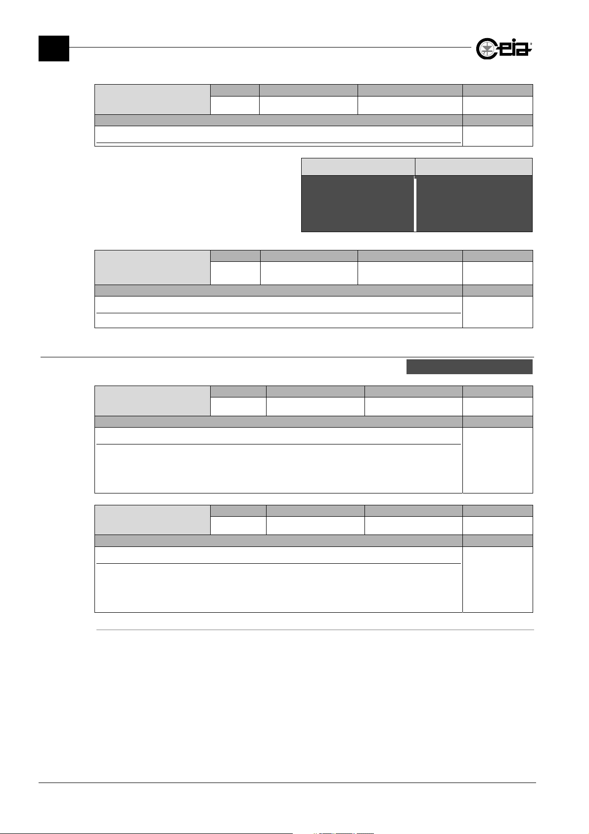
Erase User
Description Models
Delete an user
Scroll the users list through the arrow keys. Press E to
select the user to be erased, then press UP to confirm or
E to cancel.
Set Bluetooth PIN
Description Models
Set the Bluetooth PIN
Needed for the remote connection with a personal computer, via Bluetooth.
3.1.1 Remote passwords
List of commands available under the Remote passwords submenu
RS232password
Description Models
Password for the Remote Programming access via RS232
This parameter select the remote access authentication way:
-
Alphanumeric value: only the password RM is required
-
Empty (RM = ‘NULL’ in remote programming): username & password valid for the local access are
required.
auxRS232passw
Description Models
Password for the Remote Programming access via Auxiliary RS232
This parameter select the remote access authentication way:
-
Alphanumeric value: only the password AURM is required
-
Empty (AURM = ‘NULL’ in remote programming): username & password valid for the local access
are required.
Remote Possible settings Standard setting Parameter
-
6 alphanumeric chars. - Global
THS/xx21E THS/xx21
=====================
erase
UTENTE1?
(SU)=YES ----- NO=(E)
[\\\\\\\\\\\\\
erase
USER01?
($)=YES |||||| NO=(E)
Remote Possible settings Standard setting Parameter
BPIN
Up to 8 alphanum.
chars.
00000000 Global
password
auxRS232passw
Remote Possible settings Standard setting Parameter
RM
6 alphanum. chars. 000006 Global
Remote Possible settings Standard setting Parameter
AURM
6 alphanum. chars. 000006 Global
All models
All models
All models
All models
16
Page 17
Product
DEFAULT
d
uct
\\\\\
]
g
g
3.2 Reset
FI002K0021v1100UK – THS/21E and THS/21 Programming Manual
PROGRAMMING PARAMETERS
3
Reset
Description Models
Alarm and fault Reset
This command restore the system from alarms and faults that require a Reset operation.
RS command does not reset the Emergency condition: in this case, the Emergency button need to
be released and the R button, if present, needs to be pressed (see Installation Manual).
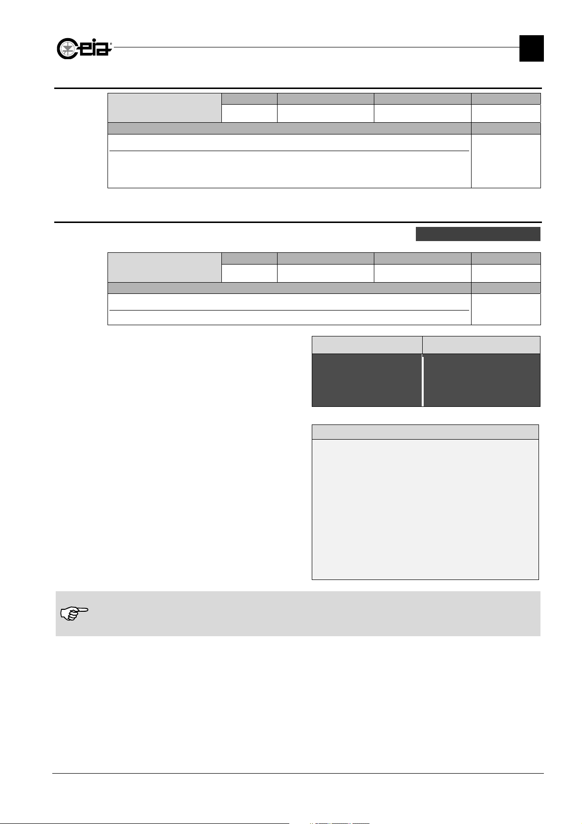
3.3 Product selection
List of commands available under the Product selection menu.
Product
Description Models
Type of product selected
Selection of a product previously entered and saved.
Local programming
The various defined products are shown on the display.
Scroll them with the arrow keys and choose the desired
product by pressing the E key. On THS/21 models,
typing letters in the search field results in a product list
restricted to the names that match that string.
Remote programming
This command displays the list of products: the current
product is shown by the “>” cursor.
To chan
value to the PI setting.
On product DEFAULT are saved all factory settings for the detection of the reference test samples, as indicated on the
Factory Acceptance Test (FAT) of the Metal Detector, included with the Installation Manual.
It is not possible to erase or to modify the DEFAULT product.
The standard configuration includes also the product P1, as a copy of DEFAULT but modifiable (and erasable).
e the current product, assign the correspondin
Remote Possible settings Standard setting Parameter
RS
- - Global
All models
Remote Possible settings Standard setting Parameter
PI
12 alphanumeric chars. - Global
All models
THS/xx21E THS/xx21
====== Pro
*DEFAULT
PROD01
PROD02
======
[\\\\\ Product
@DEFAULT
PROD01
PROD02
POW003
BRWNSUGAR
{|||||||||||||||||||}
Search: #___________
Remote display
#PI<ENTER>
Default
ProdA
> ProdB
ProdC
#PI ProdA<ENTER>
#PI<ENTER>
Default
> ProdA
ProdB
ProdC
#
17
Page 18
FI002K0021v1100UK – THS/21E and THS/21 Programming Manual
Product
\\\\\
]
g
g
Product
SUCAR01
\\]
3
PROGRAMMING PARAMETERS
3.4 Products
List of commands available under the Products menu
Product
Description Models
Type of product selected
Selection of a product previously entered and saved.
Local programming
The various defined products are shown on the display.
Scroll them with the arrow keys and choose the desired
product by pressing the E key. On THS/21 models,
typing letters in the search field results in a product list
restricted to the names that match that string.
Remote programming
This command displays the list of products: the current
product is shown by the “>” cursor.
To chan
value to the PI setting.
On product DEFAULT are saved all factory settings for the detection of the reference test samples, as indicated on the
Factory Acceptance Test (FAT) of the Metal Detector, included with the Installation Manual.
It is not possible to erase or to modify the DEFAULT product.
The standard configuration includes also the product P1, as a copy of DEFAULT but modifiable (and erasable).
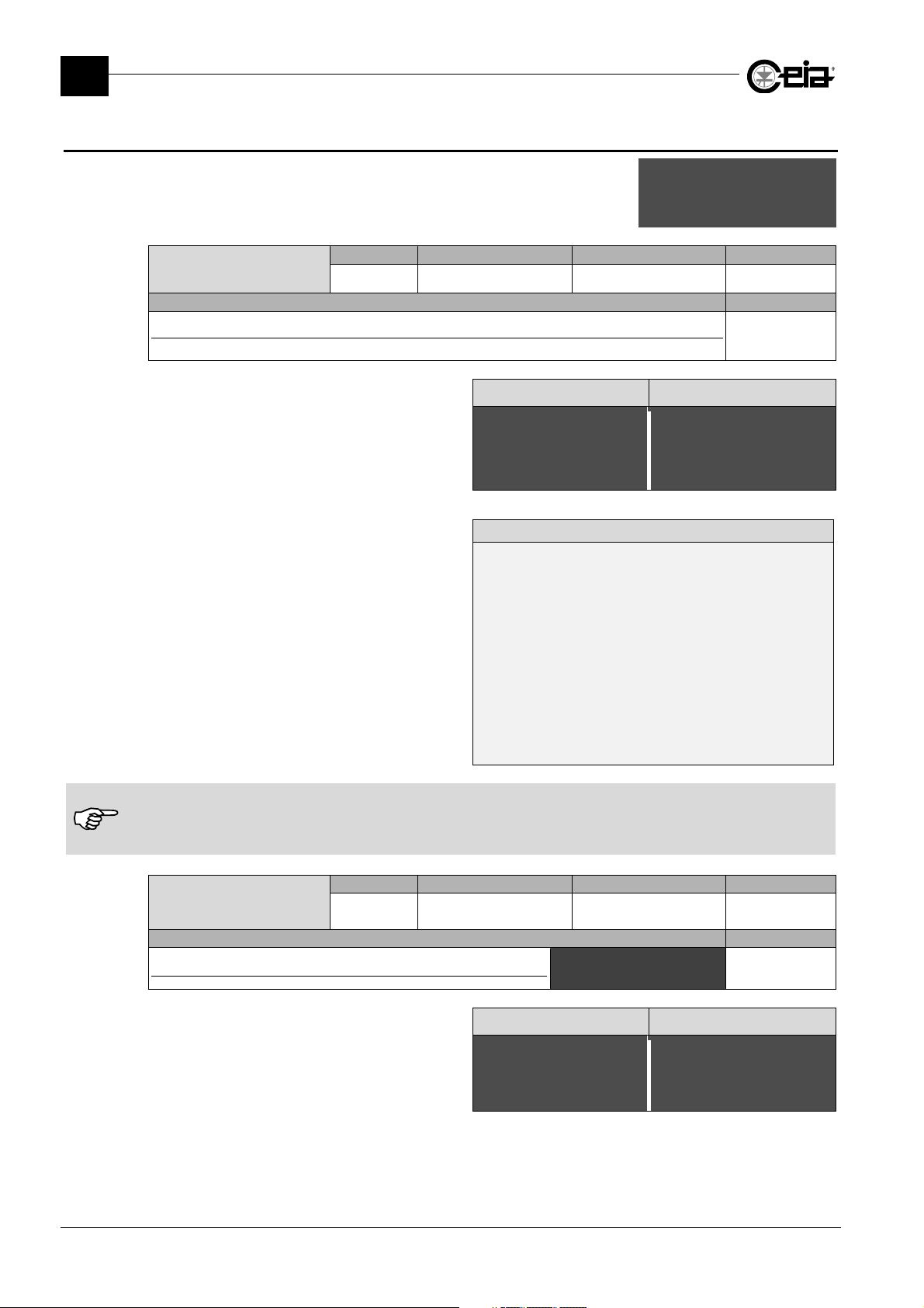
Rename product
Description Models
Rename the product
Changes the name of the current product.
It is not possible to rename the product DEFAULT.
Remote Possible settings Standard setting Parameter
PI
12 alphanumeric chars. - Global
e the current product, assign the correspondin
Remote Possible settings Standard setting Parameter
PN
12 alphanumeric chars. -
THS/xx21E THS/xx21
====== Product ======
*DEFAULT
PROD01
PROD02
Remote display
#PI<ENTER>
Default
ProdA
> ProdB
ProdC
#PI ProdA<ENTER>
#PI<ENTER>
Default
> ProdA
ProdB
ProdC
#
Rename~product~~~~~~@
THS/xx21E THS/xx21
== Rename product ==
SUGA#_______
--------------------
Rename product
New product
Erase product
Prod. Barcode
Save prod.to USB
Load prd from USB
All models
[\\\\\ Product
@DEFAULT
PROD01
PROD02
POW003
BRWNSUGAR
{|||||||||||||||||||}
Search: #___________
Related to the
current product
All models
[\ Rename product
SUGA#_______
{|||||||||||||||||||}
18
Page 19
FI002K0021v1100UK – THS/21E and THS/21 Programming Manual
Product
SUGAR01
ying
\\\\]
Product
SUGAR01
\\]
\\\\\\\\\
]
PROGRAMMING PARAMETERS
Remote Possible settings Standard setting Parameter
New product
NW
12 alphanumeric chars. - Global
Description Models
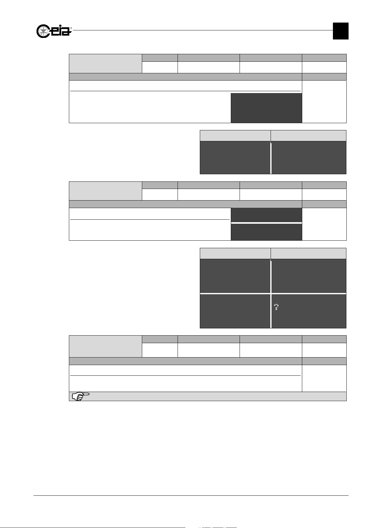
Creation of a new product
Create a new product. The maximum number of products is 500 for
the THS/21 series and 250 for the THS/21E series.
Rename product
[\\\ New product \\\]
BISC#_______
{|||||||||||||||||||}
All models
The initial parameters of the new product will be the
same of the product selected when the new product is
created. Cop
the DEFAULT product, parameters FD,
=== New product ====
BISC#_______
--------------------
THS/xx21E THS/xx21
[\\ New product
BISC#_______
{|||||||||||||||||||}
SD and ND will not be copied.
Remote Possible settings Standard setting Parameter
Erase product
EP
12 alphanumeric chars. - Global
Description Models
3
Elimination of a product
Rename product
All models
Scroll the product list using the arrow keys, and select
the product to be erased pressing the E key.
A confirmation is needed to complete the operation.
It is not possible to erase the product DEFAULT.
=== Erase product ===
DEFAULT
PROD01
*PROD02
=====================
erase
PROD02?
(UP)=YES ----- NO=(E)
THS/xx21E THS/xx21
[\\ Erase product
DEFAULT
PROD01
@PROD02
SUGAR01
{|||||||||||||||||||}
Search: #_________
[\\\\\\\\\\
erase
PROD02?
{|| $=YES || E=NO ||}
Remote Possible settings Standard setting Parameter
Prod. barcode
BARC
- -
Related to the
current product
Description Models
Product barcode
This function show the barcode related to the current product. If a barcode has not been yet
All models
assigned, the result is “NULL”.
This function is visible only if the barcode reader menu has been activated (see BE parameter).
19
Page 20
FI002K0021v1100UK – THS/21E and THS/21 Programming Manual
Select
)
[ Select
[
\\\\\\\
]
[
\\\\\\]
3
PROGRAMMING PARAMETERS
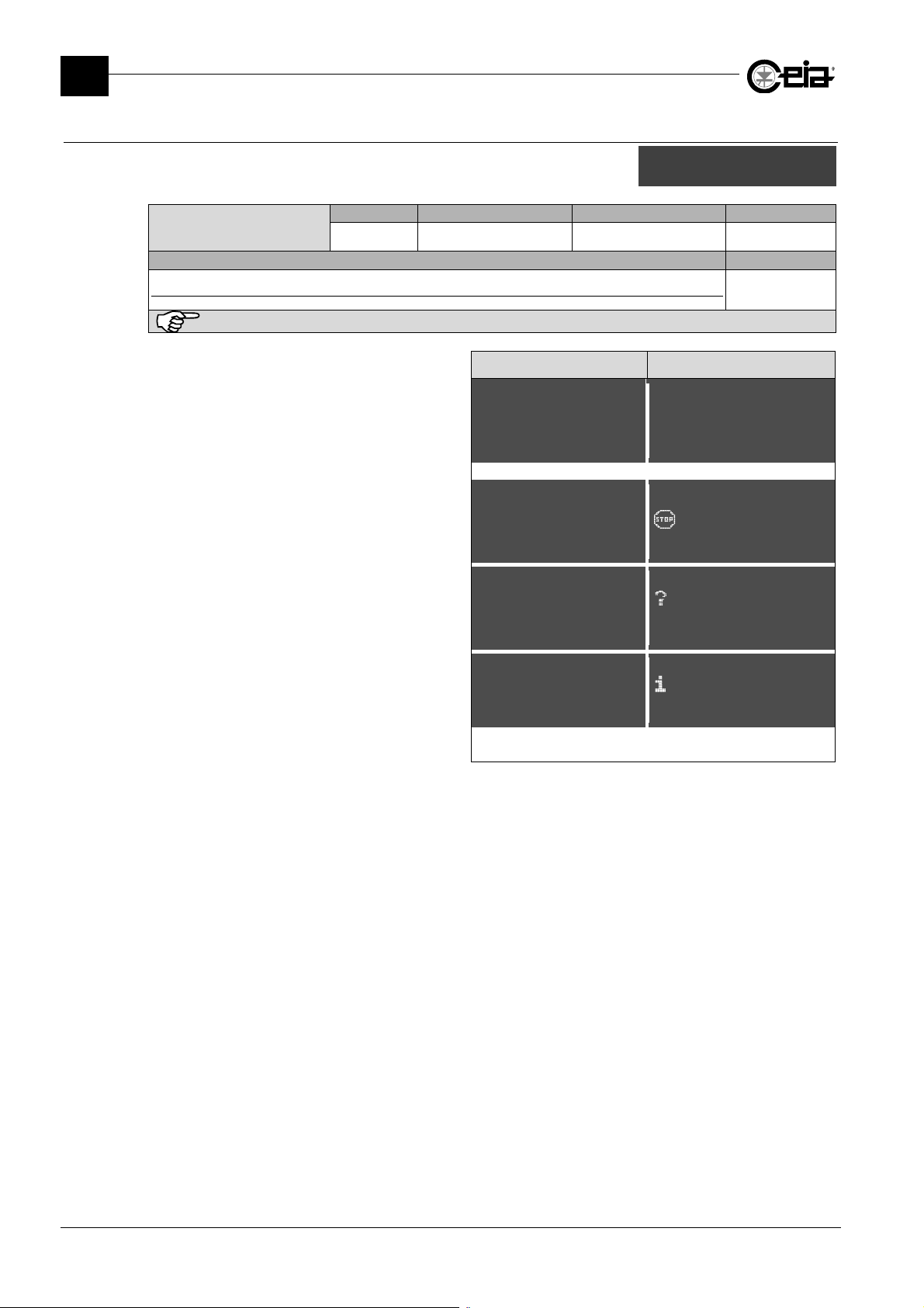
3.4.1 Save prod.to USB
List of commands available under the Save prod.to USB submenu.
This menu is available only on models with IXC card installed.
Select product(s)
Description Models
Selection of Products to save to USB
This command is available only if IXC=ON
Press E and select each Product to be saved.
A full circle icon identifies all selected products.
At the end, keep E key pressed for 3 seconds.
Save all products
product(s
Remote Possible settings Standard setting Parameter
-
- - Global
All models
THS/xx21E THS/xx21
= Select product(s) =
-PROD01
*-PROD03
+PROD09
¼PROD01
@¼PROD03
½PROD05
¼PROD09
{||||||||||||||||||||}
Search :#___________
product (s) ]
If an USB key is not already inserted on the Metal
Detector USB plug, a message will be shown at the
operation start.
In case one or more Products already exist in USB
memory, press & to overwrite all selected Products (or
P to null the saving ), otherwise decide one by one,
pressing $ to overwrite or E to not overwrite.
Each selected Product is saved as:
:/Ceia/Products/SNxxxxxxxxxxx/
=====================
Insert USB memory
Press P to exit
---------------------
Overwrite
PROD05?
(UP)=YES NO=(E)
(DW)=ALL NONE=(P)
=====================
Done
---------------------
ProductName.tpr
where xxxxxxxxxxx is the Metal Detector serial number.
[\\\\\\\\\\\\\\\\\\\]
Insert USB memory
Press P to exit
{|||||||||||||||||||}
\\\\\\\\\\\\\
Overwrite
PROD05?
$=YES NO=E
{ &=ALL |||||| NONE=P}
\\\\\\\\\\\\\
Done
{|||||||||||||||||||}
20
Page 21
FI002K0021v1100UK – THS/21E and THS/21 Programming Manual
\\\\\\\\\
]
\\\\\\\\\\]
\\\\\\\\\
]
PROGRAMMING PARAMETERS
Remote Possible settings Standard setting Parameter
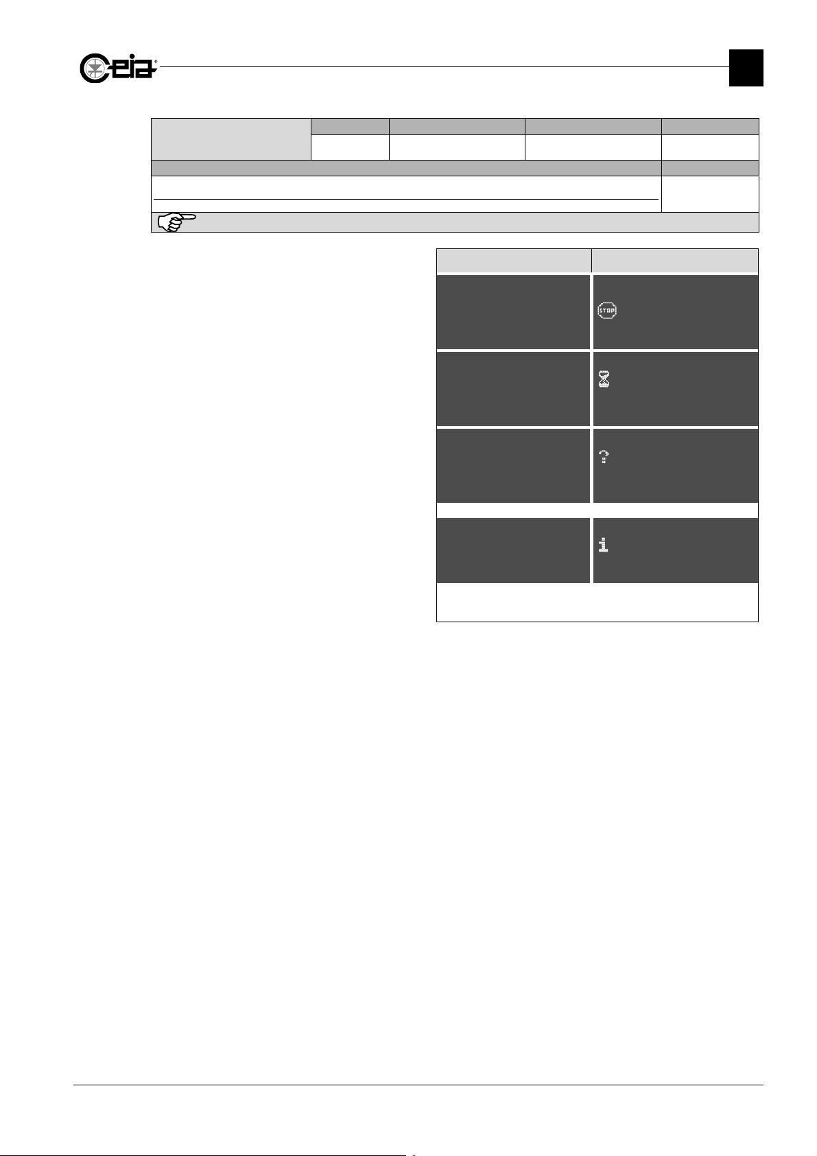
Save all products
-
- - Global
Description Models
Save all Products to USB memory
This command is available only if IXC=ON
All models
If an USB key is not already inserted on the Metal
Detector USB plug, a message will be shown at the
operation start.
All products are automatically saved to USB memory.
=====================
Insert USB memory
Press P to exit
---------------------
=====================
WAIT
CAN TAKE MINUTES
---------------------
THS/xx21E THS/xx21
[\\\\\\\\\\\\\\\\\\\]
Insert USB memory
Press P to exit
{|||||||||||||||||||}
[\\\\\\\\\\
WAIT
CAN TAKE MINUTES
{|||||||||||||||||||}
3
In case one or more Products already exist in USB
memory, press & to overwrite all selected Products (or
P to null the saving ), otherwise decide one by one,
pressing $ to overwrite or E to not overwrite.
Each selected Product is saved as:
:/Ceia/Products/SNxxxxxxxxxxx/
Overwrite
PROD05?
(UP)=YES NO=(E)
(DW)=ALL NONE=(P)
=====================
Done
---------------------
ProductName.tpr
where xxxxxxxxxxx is the Metal Detector serial number.
[\\\\\\\\\\
Overwrite
PROD05?
$=YES NO=E
{ &=ALL |||||| NONE=P}
[\\\\\\\\\\
Done
{|||||||||||||||||||}
21
Page 22
FI002K0021v1100UK – THS/21E and THS/21 Programming Manual
[\ Select di
\
]
Select
)
[ Select
[
\\\\\\\
]
diff
t
[
\\\\\\\
]
[
\\\\\\]
[
\\\\\\]
3
PROGRAMMING PARAMETERS
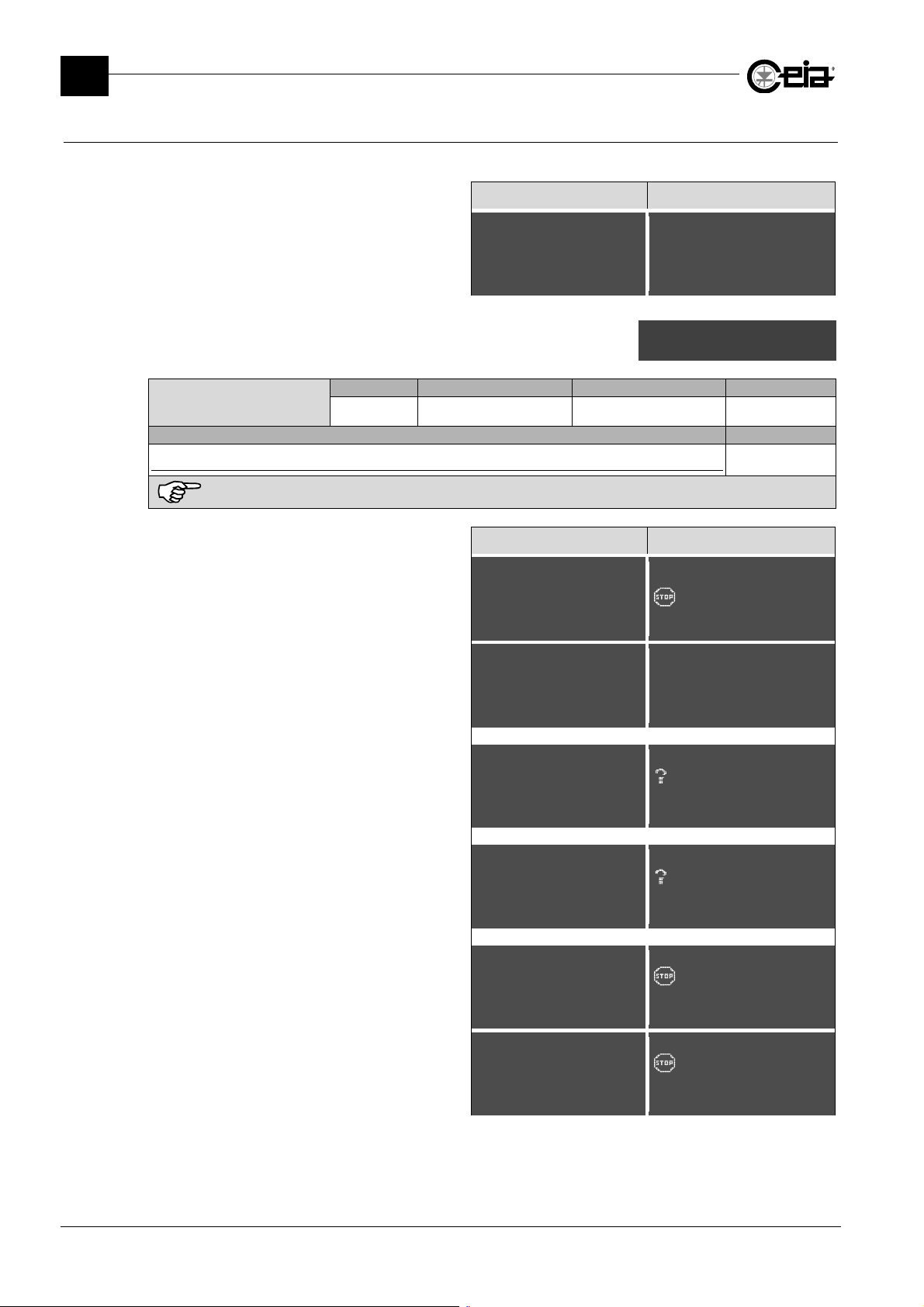
3.4.2 Load prd. from USB
This menu is available only on models with IXC card installed.
Enter in this Menu and select the Metal Detector to copy
the Products from. Press E to select.
List of commands available under the Load prd. from USB
submenu.
Select product(s)
Description Models
Load Products settings from USB memory
This command is available only if IXC=ON
If an USB key is not already inserted on the Metal
Detector USB plug, a message will be shown at the
operation start.
In case one or more Products already exist in USB
memory, press & to overwrite all selected Products (or
P to null the saving ), otherwise decide one by one,
pressing $ to overwrite or E to not overwrite.
THS/xx21E THS/xx21
== Select directory =
*+SN2110021111
+SN2110021112
+SN2110021115
@+SN2110021111
+SN2110021112
+SN2110021115
+SN2110021116
+SN2110021117
{||||||||||||||||||||}
Load all
product(s
rectory
Remote Possible settings Standard setting Parameter
-
- - Global
All models
THS/xx21E THS/xx21
=====================
Insert USB memory
Press P to exit
---------------------
= Select product(s) =
-PROD01
*-PROD03
+PROD09
[\\\\\\\\\\\\\\\\\\\]
Insert USB memory
Press P to exit
{|||||||||||||||||||}
¼PROD01
@¼PROD03
½PROD05
¼PROD09
{|||||||||||||||||||}
Search:#___________
product(s) ]
In case one or more Products already exist into the
Metal Detector, press & to overwrite all selected
Products (or P to null the saving ), otherwise decide one
by one, pressing $ to overwrite or E to not overwrite.
It is possible to import products created on other Metal
Detectors (of the same model), but with different probe
dimensions.
In this case, for this products, can be necessary to
Overwrite
PROD05?
(UP)=YES NO=(E)
(DW)=ALL NONE=(P)
Size is
Load PROD05?
(UP)=YES NO=(E)
perform a new Autolearn procedure.
It is not possible to import products created on different
Metal Detector models.
The product DEFAULT and the current product cannot
be overwritten.
=====================
PROD05
Not compatible
(P)=EXIT CONT.=(E)
=====================
Product in use
(P)=EXIT CONT.=(E)
---------------------
eren
\\\\\\\\\\\\\
Overwrite
PROD05?
$=YES NO=E
{ &=ALL |||||| NONE=P}
\\\\\\\\\\\\\
Size is different
Load PROD05?
{ $=YES ||||||| NO=E }
\\\\\\\\\\\\\
PROD05
Not compatible
{ P=EXIT || CONT.=E }
\\\\\\\\\\\\\
Product in use
{ P=EXIT || CONT.=E }
22
Page 23
FI002K0021v1100UK – THS/21E and THS/21 Programming Manual
\\\\\\\\\
]
\\\\\\\\\
]
\\\\\\\\\\]
diff
t
\\\\\\\\\\]
\\\\\\\\\
]
\\\\\\\\\
]
PROGRAMMING PARAMETERS
Remote Possible settings Standard setting Parameter
Load all
-
- - Global
Description Models
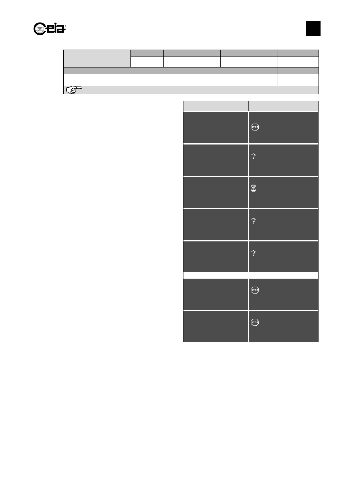
Load all Products settings from USB memory
This command is available only if IXC=ON
All models
If an USB key is not already inserted on the Metal
Detector USB plug, a message will be shown at the
operation start.
A confirmation is needed.
All products are automatically loaded from USB memory.
=====================
Insert USB memory
Press P to exit
---------------------
=====================
Do you confirm?
(UP)=YES NO=(E)
---------------------
=====================
WAIT
CAN TAKE MINUTES
---------------------
THS/xx21E THS/xx21
[\\\\\\\\\\\\\\\\\\\]
Insert USB memory
Press P to exit
{|||||||||||||||||||}
[\\\\\\\\\\
Do you confirm?
{|| $=YES || NO=E ||}
{|||||||||||||||||||}
[\\\\\\\\\\
WAIT
CAN TAKE MINUTES
{|||||||||||||||||||}
3
In case one or more Products already exist into Metal
Detector, press & to overwrite all selected Products (or
P to null the saving ), otherwise decide one by one,
pressing $ to overwrite or E to not overwrite.
It is possible to import products created on other Metal
Detectors (of the same model), but with different probe
dimensions.
In this case, for this products, can be necessary to
Overwrite
PROD05?
(UP)=YES NO=(E)
(DW)=ALL NONE=(P)
Size is
Load PROD05?
(UP)=YES NO=(E)
eren
[\\\\\\\\\\
Overwrite
PROD05?
$=YES NO=E
{ &=ALL |||||| NONE=P}
[\\\\\\\\\\
Size is different
Load PROD05?
{ $=YES ||||||| NO=E }
perform a new Autolearn procedure.
It is not possible to import products created on different
Metal Detector models.
The product DEFAULT and the current product cannot
be overwritten.
=====================
PROD05
Not compatible
(P)=EXIT CONT.=(E)
=====================
Product in use
(P)=EXIT CONT.=(E)
---------------------
[\\\\\\\\\\
PROD05
Not compatible
{ P=EXIT || CONT.=E }
[\\\\\\\\\\
Product in use
{ P=EXIT || CONT.=E }
23
Page 24
FI002K0021v1100UK – THS/21E and THS/21 Programming Manual
Autol
3
PROGRAMMING PARAMETERS
3.5 Autolearn
List of commands available under the Autolearn menu.
Autolearn
Description Models
Product autolearn
This command activates the Autolearn procedure, in which the Metal Detector set automatically the
best Product settings for the “product effect” compensation.
To start the Autolearn, select ON and exit from programming. The request for the product transit will
be shown on the display. See also TN parameter.
The parameter returns to OFF automatically at the end of procedure. See paragraph “Programming
the metal detector according to the kind of product”.
Aut.det.mode sel
Description Models
Autolearn detection mode selection
If ADMS is set to ON the Autolearn procedure will automatically determine the best Detection mode
for the product in transit.
If set to OFF the Autolearn procedure will be performed only on current Detection mode.
Multi-band
Description Models
Autolearn band selection
If MB is set to ON the Autolearn procedure will automatically determine the best band for the product
in transit.
If set to OFF the Autolearn procedure will be performed only on current band.
Min.transits numb
Description Models
Minimum number of product transits for Autolearn
TN=1 is enough for uniform products. In the case of non-uniform products, increase TN in order to
have a more accurate product autolearn.
earn
Aut.det.mode sel
Multi-band
Min.transits numb
Remote Possible settings Standard setting Parameter
LE
Remote Possible settings Standard setting Parameter
ADMS
Remote Possible settings Standard setting Parameter
MB
Remote Possible settings Standard setting Parameter
TN
With ADMS=ON (or MB=ON) more transits could be required, depending on the product type.
ON / OFF OFF
ON / OFF ON
ON / OFF ON
1 – 10 1
Global
All models
Global
Only on
THS/xxMS21
Global
Only on
THS/xx21E-3F
Global
All models
24
Page 25
FI002K0021v1100UK – THS/21E and THS/21 Programming Manual
Metal
3.6 Autolearn-advanc
List of commands available under the Autolearn-advanc menu
Remote Possible settings Standard setting Parameter
Metal optimiz.
MOPT
Description Models
Selection of the operating band criteria during autolearn
During the autolearn procedure, the Metal Detector choose automatically the best detection mode,
according to MOPT value.
-
AVRG: Optimization for Ferrous metals, non Ferrous metals and Stainless Steel detection
-
BFE: Optimization for ferrous metals detection
-
BNFE: Optimization for non-ferrous metals detection
-
BSS: Optimization for stainless steel detection
Autolearn sens.
Remote Possible settings Standard setting Parameter
ASE
Description Models
Automatic Sensitivity adjustment during Autolearn
ASE =ON: the Metal Detector, during the Autolearn procedure, adjust also the sensitivity value
according to SA and MASE parameters.
ASE=OFF: during the Autolearn procedure, the current sensitivity value is not changed.
Sens. margin
Remote Possible settings Standard setting Parameter
SA
Description Models
Margin of sensitivity
The application of this parameter has effect only if ASE=ON and after the Autolearn.
After the Autolearn, the Sensitivity value is automatically set in order to guarantee a margin (defined
by SA parameter) for the corresponding Alarm threshold level, in order to avoid that signal
variations, due to non-uniformity in product characteristics, could cause false Alarms.
The higher are signal variations, the greater should be SA value, the lower will be the Sensitivity
value. Set SA higher than 25 just in case of product with very strong signal variation (for example:
bulk and wet product). The value of 25 corresponds to a ratio of about 2.5 between the alarm
threshold and the product signal.
Max learn sens
Remote Possible settings Standard setting Parameter
MASE
Description Models
Maximum sensitivity value adjustment during Autolearn
Maximum sensitivity value that can be set by the Autolearn procedure.
The application of this parameter has effect only if ASE=ON and after the Autolearn.
AVRG / BFE
BNFE / BSS
ON / OFF ON
10 – 50 25
100 – 299 290
PROGRAMMING PARAMETERS
optimiz.
Autolearn sens.
Sens. margin
Max learn sens
Vibr.immunity
Ej.during autlr
AVRG
Global
Only for
THS/xxMS21
and
THS/xx21E-3F
Global
All models
except
THS/MN21
Global
All models
Global
All models
3
25
Page 26
FI002K0021v1100UK – THS/21E and THS/21 Programming Manual
S
itivit
3
PROGRAMMING PARAMETERS
Vibr.immunity
Remote Possible settings Standard setting Parameter
VI
Description Models
Vibration immunity
This parameter has effect only after the Autolearn execution.
Setting VI between 1 and 250, the Autolearn procedure optimizes the Product settings both for the
best detection sensitivity and against possible mechanical vibrations. Increasing this value will result
in a higher vibrations immunity of the Metal Detector, but the detection sensitivity could result lower
respect with VI=0.
If VI is set to 0, during the Autolearn procedure the Metal Detector will optimize only the detection
sensitivity. Set VI≠0 only if strictly necessary.
Ej.during autlr
Remote Possible settings Standard setting Parameter
EDA
Description Models
Ejection during Autolearn
Set EDA=ON to activate the ejection during the Autolearn in order to rejected the product passed.
See also EM parameter.
Available only with EM=F
0 – 250 0
ON/OFF OFF
Global
All models
except
THS/MN21
and
THS/xx21E
Global
All model
3.7 Detection
List of commands available under the Detection menu
Remote Possible settings Standard setting Parameter
Sensitivity
SE
Description Models
Alarm trigger threshold level
The higher is SE value, the lower is the Alarm trigger threshold level for the signal received from the
Metal Detector, to be set depending on the product signal.
The SE value concurs, with the other Product settings (set by Autolearn), to the detection
performance. For dry and non magnetic product, the higher is the SE value, the lower is the metal
mass that can be detected.
If ASE=ON, after the product Autolearn, the Metal Detector set automatically the highest possible SE
value for the current product, according to SA and MASE parameters.
If set manually, choose the right value not to have false Alarms (depending on the product
characteristics and on the environment) or bad detection performance.
Remote Possible settings Standard setting Parameter
Detection mode
DM
Description Models
Detection mode
The Detection Mode must be selected according to the kind of product to be inspected.
If ADMS=ON, the Metal Detector performs the Autolearn selecting also automatically the best DM
value suitable for the product.
The manual selection of DM always requires to perform successively the Autolearn procedure.
The default value of 0 is suitable for dry products.
It is recommended to set ADMS=ON to permit the automatic best Detection Mode selection. Selecting
manually DM value does not guarantee the best possible Detection performance.
0 - 299 -
0 - 9 0
ens
Detection mode
TX program
Band
y
Related to the
current product
All models
Related to the
current product
Only on
THS/xxMS21
26
Page 27
FI002K0021v1100UK – THS/21E and THS/21 Programming Manual
PROGRAMMING PARAMETERS
Remote Possible settings Standard setting Parameter
TX program
TP
Description Models
Transmission Program
This parameter setting determines
set by the Autolearn procedure. The default value of 0 is suitable for dry product.
Changing manually the value of TP can cause an incorrect detection operation of the Metal Detector!
In this case, repeat the Autolearn procedure.
Band
the best minimization for the product effect and it is automatically
Remote Possible settings Standard setting Parameter
BA
Description Models
Band
The Band must be selected according to the kind of product to be inspected.
If MB=ON, its value is determined automatically by the system during the Autolearn procedure.
The manual selection of BA always requires to perform successively the Autolearn procedure.
The default value of HIGH is suitable for dry products.
It is recommended to set MB=ON to permit the automatic best Band selection. Selecting manually BA value
does not guarantee the best possible Detection performance.
0 - 17999 0
LOW / MEDIUM / HIGH
HIGH
Related to the
current product
Only on
THS/xx21E
Related to the
current product
Only on
THS/21E-3F
3
27
Page 28
FI002K0021v1100UK – THS/21E and THS/21 Programming Manual
Ejecti
3
PROGRAMMING PARAMETERS
3.8 Ejection
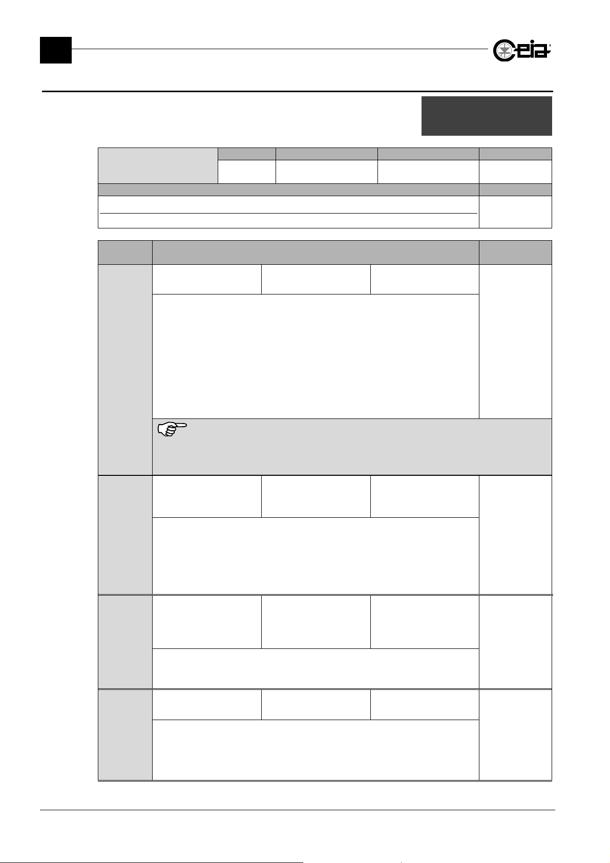
List of commands available under the Ejection menu
Ejection mode
Description Models
Ejection mode
Selection of ejection mode for contaminated material. See Installation Manual.
Ejection
mode
B
Ej. distance
Ejection time
Pack length
Ej.st.sync.area
Ej.en.sync.area
on mode
Remote Possible settings Standard setting Parameter
EM
B / F / S / SB / R
FS / H / HA / HB
-
Related to the
current product
see table below
Description Models
Used for bulk product
with manual removal
No photocell required -
After an Alarm:
-
With Conveyor Control System or using an encoder, the belt stops after a time set
by ED parameter; otherwise the EJECT Relay is activated after ED/BS time (if
Following Conveyor Input is used, the time ED/BS is counted only during the input
All models
activation). A manual reset is requested.
-
the contaminated product must be manually removed.
-
the Alarm must be reset manually (by Detector Reset button on Conveyor Control
System or using E key or by RESET input activation).
-
the belt transport must be restarted.
See ED, BS, FC.
F
S
The Metal Detector does not check if there are any subsequent fragments in the material
immediately following to that causes alarm: all material between the probe entrance and ejection position
shall be eliminate. To minimize waste of material it is advisable to select a low setting for the ED
parameter.
Used for bulk product
with automatic ejection
No photocell required
Ideal for air blow ejector,
retractable belt and
flap deviator
After an Alarm:
-
EJECT Relay and the Ejector are activated after ED/BS time, for ET time. (if
All models
Following Conveyor Input is used, the time ED/BS is counted only during the input
activation).
-
the contaminated product is automatically ejected
See ED, ET, ERT, BS, FC.
Used for packed product
(properly aligned and
spaced) and automatic
ejection
Photocell required Ideal for piston ejector
All models
After an Alarm with Synchronization Photocell activation, the operation mode is like
for EM=F. See ED, ET, ERT, BS, FC, PH, PD.
Used for packed product
with manual removal
Photocell required -
SB
After an Alarm with Synchronization Photocell activation, the operation mode is like
for EM=B. See ED, BS, FC, PH, PD.
28
All models
Page 29
Ejection
mode
R
FS
FI002K0021v1100UK – THS/21E and THS/21 Programming Manual
PROGRAMMING PARAMETERS
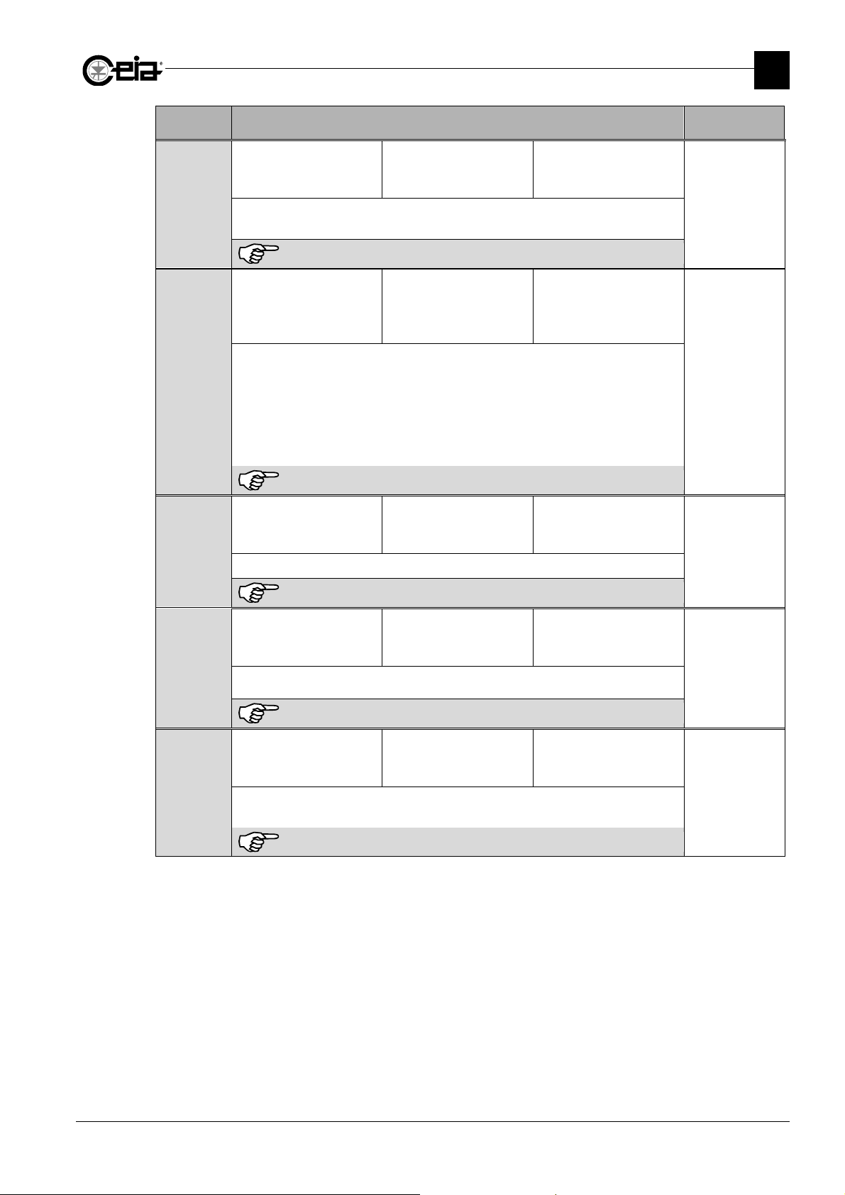
Description Models
Reversed belts.
Used for bulk product
In case of Alarm, the conveyor belt direction is reversed for a distance ED.
Available only with Conveyor Control System.
Do not select with modular belt systems.
Used for packed
(aligned, poorly spaced)
or bulk product, and
automatic ejection
Includes automatic set-aside of contaminated material with Synchronization and
Ejection Check photocells.
-
EJECT Relay and the Ejector are activated after ED/BS time, for the belt area
equal to Antenna Width + 2PLEN + eventually (EE+ES), symmetrically respect to
Antenna center.
-
the contaminated product is automatically ejected
See ECPD, ECK, ECKA, ED, EE, ERT, ERF, ES, BS, FC, PD, PH, PL, PLEN, EE, ES
No photocell required
Photocells required
Usable only with flat
belts, capable of
reversed running
All models
Ideal for air blow ejector
or retractable belt
All models
3
See Installation Manual.
Used for bulk product
from filling machine to
clipping machine
-
HA
Includes automatic ejection with automatic filling cycle restart.
See Installation Manual.
Used for bulk product
from filling machine to
clipping machine
-
H
Includes automatic ejection with filling cycle restart from clipper machine
See Installation Manual.
Used for bulk product
from filling machine to
clipping machine
HB
Includes automatic ejection with filling cycle restart from clipper machine after Metal
Detector Reset by external button
See Installation Manual.
-
Ideal for
THS/PLVM21 series
Ideal for
THS/PLVM21 series
Ideal for
THS/PLVM21 series
Only for
THS/Gxx
THS/PLxx
THS/PLVxx
THS/FFVxx
Only for
THS/Gxx
THS/PLxx
THS/PLVxx
THS/FFVxx
Only for
THS/Gxx
THS/PLxx
THS/PLVxx
THS/FFVxx
29
Page 30
FI002K0021v1100UK – THS/21E and THS/21 Programming Manual
3
PROGRAMMING PARAMETERS
Remote Possible settings Standard setting Parameter
Ej. distance
ED
Description Models
Distance of ejection system from probe or photocell
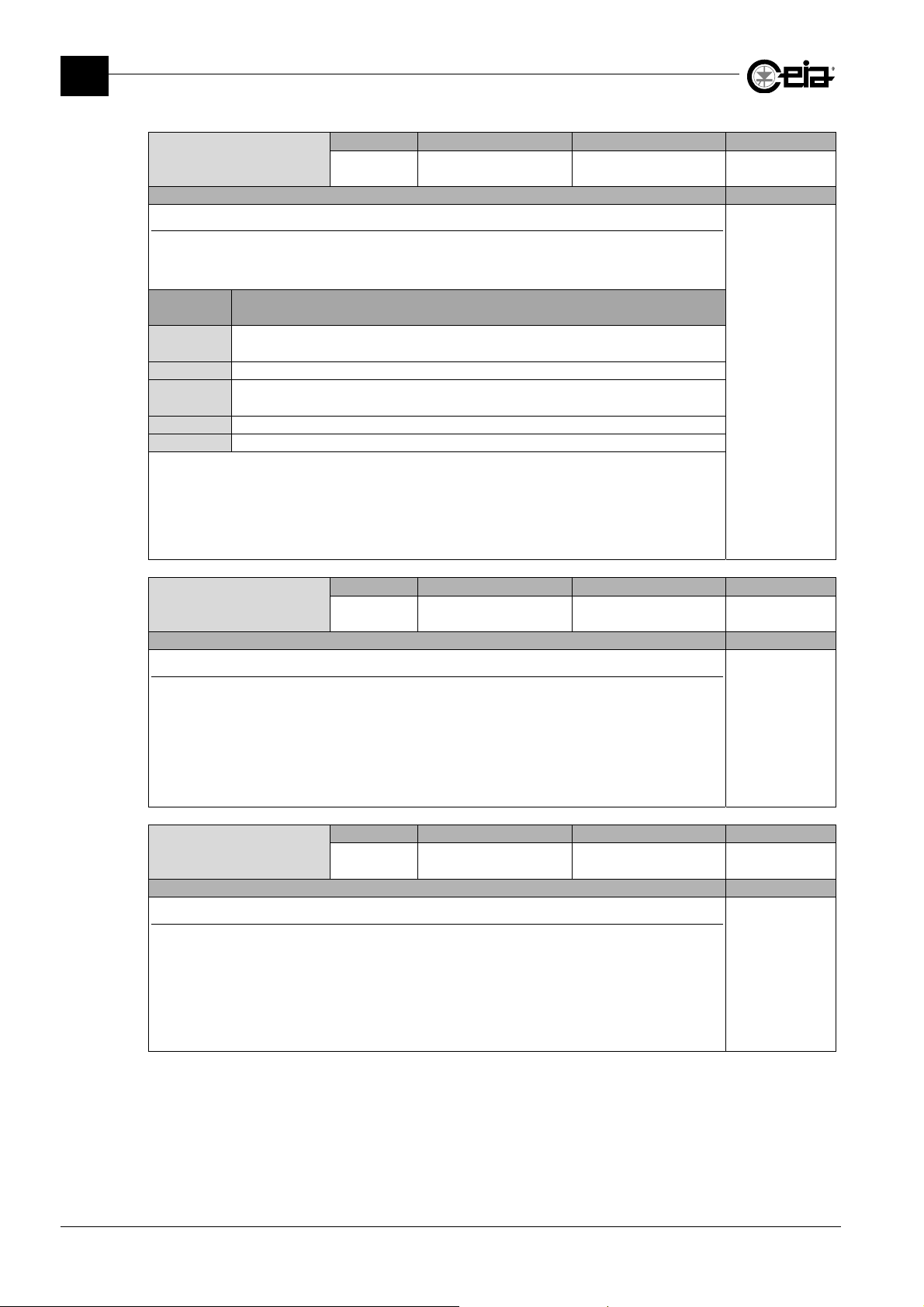
This parameter indicates the position of the ejection system and it should be set according to the
Ejection mode (EM parameter) as shown below.
For the correct setting of ED, see also the Installation Manual.
Ejection
mode
B
F, FS Approx. distance between the Antenna center and the ejector position
SB
S Distance between the Synchronization Photocell and the ejector position
R Approx. distance ran reversed by the conveyor belt, after the alarm
The time ED/BS is the delay, from the Alarm, after which the belt stops or the ejector is activated.
With Conveyor Control System or using an encoder, the delay is counted only during the belt
movement.
For systems using FOLLOWING CONVEYOR input, it is counted only during its own activation (see
FC parameter).
Ejection time
Meaning
Approx. distance between the Antenna center and the point where the contaminated
product should stop
Distance between the Synchronization Photocell and the point where the
contaminated product should stop
Remote Possible settings Standard setting Parameter
ET
Description Models
Ejector activation time
Set ET to the minimum time the ejector (and the EJECT Relay) remain activated after an Alarm,
allowing the correct ejection of the contaminated product.
Depending on EM, the real time the ejector will be activated is:
-
if EM=S : ET
-
If EM=F : ET + Alarm time (approx. the transit time of the metal mass through the probe)
Remote Possible settings Standard setting Parameter
Pack length
PLEN
Description Models
Nominal length of the pack
Nominal length of the product pack (in millimetres).
Setting PLEN value, the minimum belt area to be cleared from contaminated product is equal to:
PLEN + Antenna Width + PLEN
The effective cleared area is taking in count also parameters EE and ES.
0 – 6000 mm -
0,01 – 30,00 s -
20 – 250 mm -
Related to the
current product
All models
Not available with EM=H, HA, HB
Related to the
current product
All models
Not available with EM=B, SB, FS
Related to the
current product
All models
Available only with EM = FS.
30
Page 31
FI002K0021v1100UK – THS/21E and THS/21 Programming Manual
PROGRAMMING PARAMETERS
Remote Possible settings Standard setting Parameter
Ej.st.sync.area
ES
Description Models
Ejection start synchronization area
Set ES (typically equal to PLEN) in order to synchronize the ejection start with the beginning of the
pack in transit.
Remote Possible settings Standard setting Parameter
Ej.en.sync.area
EE
Description Models
Ejection end synchronization area
Set EE (typically equal to PLEN) in order to synchronize the ejection end with the ending of the pack
in transit.
0 – 250 mm -
Available only with EM = FS.
0 – 250 mm -
Available only with EM = FS.
Related to the
current product
All models
Related to the
current product
All models
3
31
Page 32
FI002K0021v1100UK – THS/21E and THS/21 Programming Manual
Prd al
3
PROGRAMMING PARAMETERS
3.9 Counters
List of commands available under the Counters menu.
Prd alarms
Description Models
Number of alarms with current product (since last counter reset)
For systems with Conveyor Control System or encoder, the Alarms are counted only during the belt
movement. For systems using FOLLOWING CONVEYOR input, the Alarms are counted only during
the input activation. For all other systems, the alarms are always counted.
To reset this counter select the parameter, press the UP key and confirm by pressing the E key.
In remote programming execute the CR command.
Prd packs
Description Models
Number of transits of packs of current product (since last counter reset)
This count is performed through the Synchronization PHOTOCELL input.
For systems with Conveyor Control System or encoder, the packs are counted only during the belt
movement. For systems using Following Conveyor input, the packs are counted only during the
Input activation. For all other systems, the packs are always counted.
To reset this counter select the parameter, press the UP key and confirm by pressing the E key.
In remote programming execute the CR command.
Tot.alarms
Description Models
Number of total alarms (since last counter reset)
This counter represents the total number of alarms, since last counter reset. The remarks done for
CA are still valid.
To reset this counter select the parameter, press the UP key and confirm by pressing the E key.
In remote programming execute the AR command.
Prd packs
Tot.alarms
Tot. packs
Work time
Remote Possible settings Standard setting Parameter
CA
Remote Possible settings Standard setting Parameter
CO
Remote Possible settings Standard setting Parameter
AC
0 – 999999999 -
0 – 999999999 -
0 – 999999999 -
arms
Related to the
current product
All models
Related to the
current product
All models
Global
All models
When CA counters increase, AC also increase, but when CA counters reset, AC is not modified.
Tot. packs
Description Models
Number of total packs (since last counter reset)
This count is performed through the PHOTOCELL input. This counter increases with all products.
The remarks done for CO are still valid.
To reset this counter select the parameter, press the UP key and confirm by pressing the E key.
In remote programming execute the OR command.
When CO counters increase, OC also increase, but when CO counters reset, OC is not modified.
32
Remote Possible settings Standard setting Parameter
OC
0 – 999999999 -
Global
All models
Page 33
FI002K0021v1100UK – THS/21E and THS/21 Programming Manual
C
tibilit
G
Remote Possible settings Standard setting Parameter
Work time
WT
- -
Description Models
Working time
This parameter returns the number of operative hours of the Metal Detector.
It is not possible to reset this counter.
3.10 Configuration
List of commands available under the Configuration menu
3.10.1 Compatibility chk
List of commands available under the Compatibility chk submenu
Gener.comp.check
Description Models
General compatibility check
This command perform a complete set of automatic checks to verify the general compatibility of the
Metal Detector system with the installation environment. Follow the requests shown on display until
the outcome is carried out. See also Installation and Maintenance Manual.
Elec.comp.check
Description Models
Electrical compatibility check
This command perform an automatic check to verify the electrical compatibility of the Metal Detector
system with the installation environment. Follow the requests shown on display until the outcome is
carried out. See also Installation and Maintenance Manual.
Belt contam.check
Description Models
Belt contamination check
This command perform an automatic belt contamination check. Follow the display message
requests. This command will not be visible if BLEN=0. See also Installation and Maintenance
Manual.
Remote Possible settings Standard setting Parameter
-
- -
Remote Possible settings Standard setting Parameter
-
- -
Remote Possible settings Standard setting Parameter
-
- -
PROGRAMMING PARAMETERS
Global
All models
ompa
Buzzer
Ext.buzzer
Language
Transmission
TX Channel
Keyb alarm reset
Keyb fault reset
Time
Date setting
Alarm time
Ejection
UP/DOWN enable
Manual motion
Stop on fault
ener.comp.check
Elec.comp.check
Belt comtam.check
Belt length
y chk
Global
All models
Global
All models
Global
All models
3
33
Page 34
FI002K0021v1100UK – THS/21E and THS/21 Programming Manual
3
PROGRAMMING PARAMETERS
Belt length
Description Models
Length of the conveyor belt
Set BLEN value to the belt total length (development). Set BLEN=0 in systems without belt.
Buzzer
Description Models
Activation of the built-in buzzer
Activation of the buzzer included in the ALM board.
Ext.buzzer
Description Models
Activation of the external buzzer
Activation of the external buzzer (HORN Output, see Installation Manual) connectable to the Metal
Detector. The external buzzer is activated with the following criteria:
-
ESO=OFF: the external buzzer is never activated
-
ESO=ON1: the external buzzer will be activated only for fault conditions.
-
ESO=ON2: the external buzzer will be activated for metal alarms and fault conditions.
In THS/FBB and other configurations with single external lamp, set ESO=ON2, because the lamp is
connected to HORN output.
Language
Description Models
Language for messages
The International Codes are used to identify each language.
Transmission
Description Models
Disabling of the Metal Detector transmitter
If set to OFF, the Metal Detector transmitter is disabled, and it is not possible to detect metals.
A message on the display advises about this condition.
The parameter is automatically set to ON if the Detector is switched off and on again.
TX channel
Description Models
Transmission channel
Selection of a specific transmission channel, in order to allow the automatic synchronization
between adjacent Metal Detectors.
Remote Possible settings Standard setting Parameter
BLEN
Remote Possible settings Standard setting Parameter
SO
Remote Possible settings Standard setting Parameter
ESO
Remote Possible settings Standard setting Parameter
LG
Remote Possible settings Standard setting Parameter
TX
Remote Possible settings Standard setting Parameter
CH
0 – 20000 mm -
ON / OFF ON
OFF / ON1 / ON2 OFF
GB / F / D / S / NL
JP / P / E / H / PL
SRB / RO / CZ
RUS / TR / I
ON / OFF ON
1 - 4 1
Global
All models
Global
All models
Global
All models
-
Global
All models
Global
All models,
except
THS/MN21
Global
All models,
except
THS/MN21
34
Page 35
FI002K0021v1100UK – THS/21E and THS/21 Programming Manual
Keyb alarm reset
Description Models
Enabling of the keyboard for direct alarm reset
This parameter set the Reset mode when manual Alarm Reset is required (i.e. after an Alarm with
EM=B). If KAR=OFF, it is possible to reset the Alarm only by Reset command (in the Programming
Menu) or pressing Reset button (Detector Reset Button on Conveyor Control System).
If KAR=ON, it is possible to reset the Alarm also
Independently from KAR value, alarms can be always manually reset through the activation of
RESET input.
Keyb fault reset
Description Models
Enabling of the keyboard for direct fault reset
This parameter set the Reset mode for not self-recovering Faults.
It is always possible to reset Faults activating the Reset command (in the Programming Menu).
-
KFR=OFF: it is possible to reset Faults only by Reset command.
-
KFR=RBO: it is possible to reset Faults also pressing Reset button (Detector Reset Button on
Conveyor Control System).
-
KFR=ON: it is possible to reset Faults also pressing the Detector Reset button on Conveyor
Control System or the E button on the keypad.
Independently from KFR value, alarms can be always manually reset through the activation of
RESET input.
Time
Description Models
Current time
HH = Hours; MM = Minutes. In remote programming, digit: TM=HH:MM
Date
Description Models
Current date
DD = Day; MM = Month; YY: Last two figures of the year.
In remote programming, digit: DA=DD/MM/YY
Alarm time
Description Models
Activation time of detector alarm relay
In case of alarm, the Alarm relay (ALARM RELAY) and the external alarm signal lamp (YELLOW
LAMP output) are activated depending of AT value:
-
AT=0, the Alarm Relay and the Alarm signal lamp are not activated.
-
AT>0: the Alarm Relay and the Alarm signal lamp are activated only for the alarm duration plus
the AT value (in seconds). When EM=B, the Alarm relay and the signal lamp are activated for AT
seconds after Alarm Reset.
-
AT=A: the Alarm Relay and the Alarm signal lamp are activated only for the Alarm duration.
-
AT=R: the Alarm Relay and the Alarm signal lamp remain active after the Alarm until manual
Alarm Reset.
Remote Possible settings Standard setting Parameter
KAR
Remote Possible settings Standard setting Parameter
KFR
Remote Possible settings Standard setting Parameter
TM
Remote Possible settings Standard setting Parameter
DA
Remote Possible settings Standard setting Parameter
AT
ON / OFF ON
pressing the E key.
ON / OFF / RBO ON
HH:MM -
DD/MM/YY -
0 – 20 s / A / R A
PROGRAMMING PARAMETERS
Global
All models
Global
All models
Global
All models
Global
All models
Global
All models
3
35
Page 36
FI002K0021v1100UK – THS/21E and THS/21 Programming Manual
3
PROGRAMMING PARAMETERS
Ejection
Remote Possible settings Standard setting Parameter
EJ
Description Models
Ejection disabling/enabling
Enabling/disabling of the ejection system according to the Ejection Mode (see EM parameter).
If disabled, shall be enabled during Metal Detector tests: a message will be shown on the display.
This parameter is automatically restored to ON at start-up.
UP/DOWN enable
Remote Possible settings Standard setting Parameter
UD
Description Models
Disabling/enabling for the belt speed adjustment
Enabling/disabling the use of arrow keys on Conveyor Control System, for the belt speed
adjustment.
If UD=ON, it is possible to adjust the belt speed with belt stopped or in movement. The belt speed is
shown on the display during the changes.
If MM=ON, it is possible to change the belt speed only entering in programming.
Manual motion
Remote Possible settings Standard setting Parameter
MM
Description Models
Disabling/enabling of the conveyor belt manual movement
Enabling/disabling the use of arrow keys on Conveyor Control System, for the manual belt
movement.
If MM=ON, it is possible to move manually the belt keeping pressed the arrow key (Up arrow for the
product transit direction, Down arrow for the reverse direction).
WARNING.
With modular conveyors, set MM=OFF to avoid damages to the conveyor transmission system.
Stop on fault
Remote Possible settings Standard setting Parameter
SF
Description Models
Disabling/enabling for the belt stop, in case of fault
If SF=ON, the belt stops immediately in case of Fault during the belt movement. With SF=OFF, in
case of Fault, the belt continues to run.
ON / OFF ON
ON / OFF ON
ON / OFF OFF
ON / OFF ON
Global
All models
Global
All models
with Conveyor
Control System
Global
All models
with Conveyor
Control System
Global
All models
with Conveyor
Control System
36
Page 37
IXC
3.11 Configuration-adv
FI002K0021v1100UK – THS/21E and THS/21 Programming Manual
PROGRAMMING PARAMETERS
3
List of parameters available under the Configuration-adv menu.
IXC presence
Description Models
Remote Possible settings Standard setting Parameter
IXC
ON / OFF - Global
Enabling of the IXC board
Setting IXC=OFF, all functions relative to the network connection and USB interface are disabled.
Anyway all events will be stored on the SCD board internal memory.
In case of IXC card, use an USB memory device exclusively dedicated to this.
presence
Backup conf.to USB
Restor.cfg.from USB
Export conf.to USB
Import cfg.from USB
Network config.
Product tracking
Inhib. time
Barcode enable
Minimum speed
Speed
Maximum speed
Filter adj
Phcell position
Phcell-MD dist.
Check phot.dist
EjON resp.time
EjOFFresp.time
K transmis.
K encoder
Diameter
TA
TA1
TA2
TA autolearn
Autotest phase
Autotest module
Autotest diagnos
Display mode
Display contrast
Dimming delay
Input logic
BIN FULL input
BIN ABSENT input
EJECT.CONF.input
PHOTOCELL input
FOLLW.CONV.input
LOW PRESSURE inp
Analysis mode
Eject.queue reset
Reverse detect
Ejec.act.if stop
EJECT RELAY logic
PREC.CONV enable
FOLL.CONV enable
Autom. Restart
Test relay mode
Aux relay mode
Stop time
Motor config.
RS232 BaudRate
auxRS232B.Rate
DTR protocol
Bounce time
Bounce t. slow
Centre belt time
All models
37
Page 38
FI002K0021v1100UK – THS/21E and THS/21 Programming Manual
[
\\\\\\]
[
\\\\\\]
fil
[
fil
\\\
]
[
\\\\\\]
3
PROGRAMMING PARAMETERS
Remote Possible settings Standard setting Parameter
Backup conf.to USB
-
Description Models
Metal Detector Configuration Backup
This command is available only if IXC=ON
If an USB key is not already inserted on the Metal
Detector USB plug, a message will be shown at the
operation start.
- - Global
All models
THS/xx21E THS/xx21
=====================
Insert USB memory
Press P to exit
---------------------
[\\\\\\\\\\\\\\\\\\\]
Insert USB memory
Press P to exit
{|||||||||||||||||||}
In case the Metal Detector configuration already exist in
USB memory, press $ to overwrite or E to not
overwrite.
The Configuration file is saved as:
:/Ceia/Configuration/
=====================
already exists
Overwrite?
(UP)=YES ----- NO=(E)
=====================
Done
---------------------
xxxxxxxxxxx.tcb
where xxxxxxxxxxx is the Metal Detector serial number.
Restor.cfg.from
USB
Remote Possible settings Standard setting Parameter
-
- - Global
Description Models
Metal Detector Configuration recovery
This command is available only if IXC=ON
If an USB key is not already inserted on the Metal
Detector USB plug, a message will be shown at the
operation start.
Select the Metal Detector serial number. It is not
possible to load the configuration file of a different Metal
Detector.
A confirmation is needed: press $ to overwrite or E to
not overwrite.
=====================
Insert USB memory
Press P to exit
---------------------
==== Select
*+SN2110021111
+SN2110021112
+SN2110021115
=====================
Do you confirm?
(UP)=YES NO=(E)
---------------------
\\\\\\\\\\\\\
already exists
Overwrite?
{| $=YES |||| NO=E |}
\\\\\\\\\\\\\
Done
{|||||||||||||||||||}
All models
THS/xx21E THS/xx21
[\\\\\\\\\\\\\\\\\\\]
Insert USB memory
Press P to exit
{|||||||||||||||||||}
e ====
\\\ Select
@+SN2110021111
+SN2110021112
+SN2110021115
+SN2110021116
+SN2110021117
{|||||||||||||||||||}
\\\\\\\\\\\\\
Do you confirm?
{|| $=YES || NO=E ||}
{|||||||||||||||||||}
e
38
Page 39
FI002K0021v1100UK – THS/21E and THS/21 Programming Manual
\\\\\\\\\
]
\\\\\\\\\
]
fil
fil
\\\
]
\\\\\\\\\
]
diff
t
\\\\\\\\\\]
\\\\\\\\\\]
PROGRAMMING PARAMETERS
Remote Possible settings Standard setting Parameter
Export conf.to USB
-
- - Global
Description Models
Export the Metal Detector Configuration for a similar Metal Detector system
This command is available only if IXC=ON
All models
If an USB key is not already inserted on the Metal
Detector USB plug, a message will be shown at the
operation start.
In case the Metal Detector configuration already exist in
USB memory, press $ to overwrite or E to not
overwrite.
=====================
Insert USB memory
Press P to exit
---------------------
=====================
already exists
Overwrite?
(UP)=YES ----- NO=(E)
THS/xx21E THS/xx21
[\\\\\\\\\\\\\\\\\\\]
Insert USB memory
Press P to exit
{|||||||||||||||||||}
[\\\\\\\\\\
already exists
Overwrite?
{| $=YES |||| NO=E |}
3
The Configuration file is saved as:
:/Ceia/Configuration/
xxxxxxxxxxx.tce
=====================
Done
---------------------
[\\\\\\\\\\
Done
{|||||||||||||||||||}
where xxxxxxxxxxx is the Metal Detector serial number.
Import cfg.from
USB
Remote Possible settings Standard setting Parameter
-
- - Global
Description Models
Import Metal Detector Configuration from a similar Metal Detector system
This command is available only if IXC=ON
All models
If an USB key is not already inserted on the Metal
Detector USB plug, a message will be shown at the
operation start.
Select the Metal Detector serial number to copy the
configuration from and press E.
A confirmation is needed: press $ to overwrite or E to
not overwrite.
=====================
Insert USB memory
Press P to exit
---------------------
==== Select
*+SN2110021111
+SN2110021112
+SN2110021115
=====================
Do you confirm?
(UP)=YES NO=(E)
---------------------
THS/xx21E THS/xx21
[\\\\\\\\\\\\\\\\\\\]
Insert USB memory
Press P to exit
{|||||||||||||||||||}
e ====
[\\\ Select
@+SN2110021111
+SN2110021112
+SN2110021115
+SN2110021116
+SN2110021117
{|||||||||||||||||||}
[\\\\\\\\\\
Do you confirm?
{|| $=YES || NO=E ||}
e
It is possible to import configuration from Metal
Detectors of the same model, installed on identical
systems, but with different probe dimensions.
The correct functioning of the systems is however to be
Size is
Load
2110021111?
(UP)=YES NO=(E)
eren
[\\\\\\\\\\
Size is different
Load
2110021111?
{ $=YES ||||||| NO=E }
verified.
It is not possible to import configurations of different
Metal Detector models.
=====================
2110021111
Not compatible
---------------------
[\\\\\\\\\\
{||||||||||||||||||||}
2110021111
Not compatible
39
Page 40
FI002K0021v1100UK – THS/21E and THS/21 Programming Manual
HN
THS2110021111
3
PROGRAMMING PARAMETERS
3.11.1 Network config.
List of commands available under the Network config. submenu.
This menu is available only on models with IXC card installed
(IXC=ON).
Remote Possible settings Standard setting Parameter
HN
HN
Description Models
Host name
Remote Possible settings Standard setting Parameter
Host protocol
HPR
Description Models
Host protocol
STAT: Static. DHCP: Dynamic Host Configuration Protocol
Remote Possible settings Standard setting Parameter
IP
IPA
Description Models
IP address
Not available with HPR=DHCP.
Remote Possible settings Standard setting Parameter
NM
NM
Description Models
Net mask
Not available with HPR=DHCP.
Remote Possible settings Standard setting Parameter
GW
Description Models
Gateway
Not available with HPR=DHCP.
DNS
Description Models
Domain Name System
Not available with HPR=DHCP.
MAC
Description Models
MAC address
GW
Remote Possible settings Standard setting Parameter
DNS
Remote Possible settings Standard setting Parameter
MAC
14 characters
alphanumeric string
STAT / DHCP - Global
from 000.000.000.000
to 255.255.255.255
from 000.000.000.000
to 255.255.255.255
from 000.000.000.000
to 255.255.255.255
from 000.000.000.000
to 255.255.255.255
- - Global
~~~~~
Host protocol STAT
IP 192. 9.201. 96
NM 255.255.255. 0
GW 192. 9.201.100
DNS 192.168. 0.100
MAC 000A26:99:18:0C
Web server ON
THSXXXXXXXXXX
(XXXXXXXXXX=S/N)
Global
@
All models
All models
192.168.127.200 Global
All models
255.255.255.0 Global
All models
- Global
All models
- Global
All models
All models
40
Page 41
FI002K0021v1100UK – THS/21E and THS/21 Programming Manual
BMB
Web server
Description Models
Web server activation
Product tracking
Description Models
Automatic adjustment to product characteristics drifts
Set FO≠OFF only in case of chemical-physical characteristics drift over time, enough to determine
variations on the received signal; the Metal Detector will automatically optimize the product
compensation, at a speed proportional to the value of FO.
Set FO≠OFF only if strictly necessary and at a value as low as possible, depending on the product
characteristics.
Inhib. time
Description Models
Inhibition time
In every model, if IN≠0, the Metal Detection capability is inhibited when INHIBITION Input is
activated. The Metal Detection capability is enabled back after IN time from Input deactivation. For
Conveyor Control System, the Metal Detection capability is also inhibited for IN time after belt start.
Set IN=0 to disable this function.
A message is shown on the display when the Metal Detector is inhibited.
Barcode enable
Description Models
Enabling code for operation with bar-code reader
6-character code supplied by CEIA and specific for each Unit.
This code enables the Metal Detector to work with a Bar-Code reader.
Settings BE with the right code enable the visualization of the Barcode Menu with all the
corresponding parameters.
Minimum speed
Description Models
Minimum product transit speed
Set this parameter value [m/min] to the minimum product transit speed.
The value range of this parameter depends on the system configuration:
-
With Conveyor Control System:
-
With Control Power Box:
Set this value as closest as possible to BS, according to the needed settings, in order to increase the Metal
Detector immunity to interferences.
Remote Possible settings Standard setting Parameter
WEBS
Remote Possible settings Standard setting Parameter
FO
Remote Possible settings Standard setting Parameter
IN
Remote Possible settings Standard setting Parameter
BE
Remote Possible settings Standard setting Parameter
BL
10
L
2
ON / OFF ON Global
OFF / 1 – 5 OFF
0,00 – 30,00 s 0
6 alphanum. chars
See below -
(see parameter KT and BL)
BMBLKT
PROGRAMMING PARAMETERS
All models
Related to the
current product
All models,
except
THS/MN21
Global
All models
-
Global
All models
Global
All models
3
41
Page 42
FI002K0021v1100UK – THS/21E and THS/21 Programming Manual
TMIBMB
3
PROGRAMMING PARAMETERS
Remote Possible settings Standard setting Parameter
Speed
BS
Description Models
Product transit speed
This parameter set the nominal value for the product transit speed [m/min].
The product transit speed is adjustable according to system configuration:
-
With Conveyor Control System: set BS to the desired belt speed, in the range BL ÷ BM.
-
With Control Power Box and without an encoder (KE=0): set BS as close as possible to the
nominal product transit speed, in the range BL ÷ BM.
-
With Control Power Box and with an encoder (KE>0): the BS parameter is not available.
Maximum speed
Remote Possible settings Standard setting Parameter
BM
Description Models
Maximum product transit speed
Set this parameter to the maximum product transit speed [
The range of this parameter depends on the system configuration:
-
With Conveyor Control System:
-
With Control Power Box:
Set this value as closest as possible to BS, according to the needed settings, in order to increase the Metal
Detector immunity to interferences.
Filter adj
L
BMBL
Remote Possible settings Standard setting Parameter
ADS
Description Models
Filter adjustment
Setting ADS on values higher than zero, the detection and ejection capabilities are increased with
high speed products; consequently the immunity is decreased.
Set ADS on negative values only in case an increased immunity to environmental noises is needed.
Always check the correct functioning of the system, after every modification of ADS parameter.
Phcell position
Remote Possible settings Standard setting Parameter
PH
Description Models
Position of the synchronization photocell relative to the probe
IN: photocell located at entrance to the probe (respect to the transit direction);
OUT: photocell located at exit from the probe (respect to the transit direction).
Phcell-MD dist.
Remote Possible settings Standard setting Parameter
PD
Description Models
Distance between Metal Detector and Synchronization photocell
Set PD to the distance between the center of the Synchronization Photocell and the nearest side of
the Probe.
2 – 250 m/min. -
See below -
m/min
K
250
-3 / +3 0
IN / OUT -
0 – 2000 mm -
Related to the
current product
All models
Global
].
All models
(see parameters MI and KT)
Global
All models
Global
All models
Available only with EM=S or SB
Global
All models
Available only with EM=S, SB or FS
42
Page 43
FI002K0021v1100UK – THS/21E and THS/21 Programming Manual
Check phot.dist
Description Models
Distance between Metal Detector and Ejection Check photocell
Set ECPD to the distance between the center of the Ejection Check Photocell and the exit side of
the Probe.
EjON resp.time
Description Models
Ejector ON response time
Set ERT to the energizing response time of the ejection system electrovalve.
EjOFFresp.time
Description Models
Ejector OFF response time
Set ERF to the de-energizing response time of the ejection system electrovalve.
K transmis.
Description Models
Transmission constant of the motor reducer unit
Set KT > 0 only with Conveyor Control System, as
indicated in the Installation Manual.
When the value of KT is altered, parameters BL and BM are automatically set to nominal values 30 x KT
and 60 x KT respectively. BL and BM can nevertheless be altered manually as well (see parameters BL
and BM).
K encoder
Description Models
Encoder constant
Set KE to the encoder ppr (pulse per revolution). If the encoder is not used, set KE=0.
After having KE and DI set, verify the correct speed measure, in I/O Status > Measures > Speed.
Diameter
Description Models
Diameter of encoder measurement wheel
Set DI to encoder measurement wheel diameter (or to the belt cylinder, with the encoder applied on
it). After having KE and DI set, verify the correct speed measure, in I/O Status > Measures.
Remote Possible settings Standard setting Parameter
ECPD
Remote Possible settings Standard setting Parameter
ERT
Remote Possible settings Standard setting Parameter
ERF
Remote Possible settings Standard setting Parameter
KT
transit_speed is in m/min
motor_frequency is in Hz
Remote Possible settings Standard setting Parameter
KE
Remote Possible settings Standard setting Parameter
DI
0 – 6000 mm -
0.000 – 2.000 s -
0.000 – 2.000 s -
0.000 – 9.999 -
0 – 1000 ppr 0
10 – 250 mm -
PROGRAMMING PARAMETERS
Global
All models
Available only with EM=S or FS
Global
All models
Available only with EM=F, S or FS
Global
All models
Available only with EM=FS
Global
KT
speedtransit
_
frequencymotor
_
All models
Global
All models
Global
All models
3
43
Page 44
FI002K0021v1100UK – THS/21E and THS/21 Programming Manual
3
PROGRAMMING PARAMETERS
TP adjustment
Description Models
Correction of the received analysis signal
This parameter is specific for each device and automatically set during TA Autolearn.
See also TL parameter.
Changing manually this value can cause an incorrect operation of the Metal Detector! In this case, execute
TA Autolearn.
TA1
Description Models
Correction of the received analysis signal
This parameter is specific for each device and automatically set during TA Autolearn.
See also TL parameter.
Changing manually this value can cause an incorrect operation of the Metal Detector! In this case, execute
TA Autolearn.
TA2
Description Models
Correction of the received signal analysis parameter
This parameter is specific to each device. This parameter must be automatically set up using the TL
command in case the SCD card is replaced.
Changing manually this value can cause an incorrect operation of the Metal Detector! In this case, execute
TA Autolearn.
TA autolearn
Description Models
TA or TA1/TA2 Autolearn
The TL command starts TA Autolearn procedure to set automatically TA value (or TA1 and TA2
values). Follow the procedure as reported in the Installation Manual.
TL is automatically set to OFF at the end of procedure.
Perform TL command only if strictly needed (for example in case of SCD replacement): a wrong execution
cause an incorrect operation of the Metal Detector. In that case, repeat correctly the procedure.
In case of environmental noises during the execution of TA Autolearn, it is possible that it will be aborted
(message “AUTOLEARN ABORTED”).
Autotest phase
Description Models
Autotest signal Phase tracking
Automatic control, continuously performed, to guarantee the maximum Metal Detector operative
stability in every condition.
Remote Possible settings Standard setting Parameter
TA
Remote Possible settings Standard setting Parameter
TA1
Remote Possible settings Standard setting Parameter
TA2
Remote Possible settings Standard setting Parameter
TL
Remote Possible settings Standard setting Parameter
ATTP
0 – 35999 -
0 – 35999 -
0 – 35999 -
ON / OFF OFF
ON / OFF ON
Global
Only on
THS/xx21E
Global
Only on
THS/xx21
Global
Only on
THS/xx21
Global
All models,
except
THS/MN21
Global
All models,
except
THS/MN21 and
THS/xx21E
44
Page 45
FI002K0021v1100UK – THS/21E and THS/21 Programming Manual
Autotest module
Description Models
Autotest signal Magnitude tracking
Automatic control, continuously performed, to guarantee the maximum Metal Detector operative
stability in every condition.
Autotest diagnos
Description Models
Activation of Autotest diagnosis
Activation of Autotest diagnosis in order to signal Antenna faulty conditions.
Display mode
Description Models
Selection of the display mode
If set to ALPHA, the display will shows 4 lines of 20 characters, without any graphic.
For applications with Programming interface emulation, set DMD=ALPHA. See also DL and DLU
parameters.
Display contrast
Description Models
Display contrast adjustment
Dimming delay
Description Models
Selection of the dimming delay
Time (in seconds) elapsing from the last display update, to the automatic contrast lowering.
Input logic
Description Models
Inputs logic
Applies to all inputs. Set this parameter (P=PNP logic, N=NPN logic) according to all input devices
logic.
If LO=P, each input line is pulled to +Vin (by pull-down resistor on ALM card) when the
corresponding connected device is activated.
If LO=N, each input line is pulled to 0V (by pull-up resistor on ALM card) when the corresponding
connected device is activated.
Refer to the Installation Manual for the electrical connections
Remote Possible settings Standard setting Parameter
ATTM
Remote Possible settings Standard setting Parameter
ATD
Remote Possible settings Standard setting Parameter
DMD
Remote Possible settings Standard setting Parameter
DC
Remote Possible settings Standard setting Parameter
DDD
Remote Possible settings Standard setting Parameter
LO
ON / OFF ON
ON / OFF ON
GRAPH / ALPHA GRAPH
2 – 115 100
10 – 900 s 60
P / N P
PROGRAMMING PARAMETERS
Global
All models,
except
THS/MN21 and
THS/xx21E
Global
All models,
except
THS/MN21 and
THS/xx21E
Global
Not available for
THS/xx21E
models
Global
All models
Global
All models
Global
All models
3
45
Page 46
FI002K0021v1100UK – THS/21E and THS/21 Programming Manual
3
PROGRAMMING PARAMETERS
BIN FULL input
Description Models
Function type of the device connected to the “BIN FULL” input
NC: Normally Closed; NO: Normally Open
Set NC or NO according to the functioning type of the connected sensor, in normal working
condition. Refer to the Installation manual for the electrical connection.
BIN ABSENT input
Description Models
Function type of the device connected to the “BIN ABSENT” input
NC: Normally Closed; NO: Normally Open.
Set NC or NO according to the functioning type of the connected sensor, in normal working
condition. Refer to the Installation manual for the electrical connection.
EJECT.CONF.input
Description Models
Function type of the device connected to the “EJECT.CONFIRMATION” in put
NC: Normally Closed; NO: Normally Open
Set NC or NO according to the functioning type of the connected sensor, in normal working
condition. If EJECTIOR POSITION CHECK input is used, its function type is complementary to IE.
Refer to the Installation manual for the electrical connection.
PHOTOCELL input
Description Models
Function type of the device connected to the “PHOTOCELL” input
NC: Normally Closed; NO: Normally Open
Set NC or NO according to the output type of the connected sensor, in normal working condition.
If EJECTION CHECK input is used, its function type is equal to IP.
Refer to the Installation manual for the electrical connection.
FOLLW.CONV.input
Description Models
Function type of the device connected to the "
NC: Normally Closed; NO: Normally Open
Set NC or NO according to the output type of the connected sensor, in normal working condition.
Refer to the Installation manual for the electrical connection.
Remote Possible settings Standard setting Parameter
IL
Remote Possible settings Standard setting Parameter
IA
Remote Possible settings Standard setting Parameter
IE
Remote Possible settings Standard setting Parameter
IP
Remote Possible settings Standard setting Parameter
IW
NC / NO -
NC / NO -
NC / NO -
NC / NO -
NC / NO -
FOLLOWING CONVEYOR
Global
All models
Global
All models
Global
All models
Global
All models
Global
" input
All models
46
Page 47
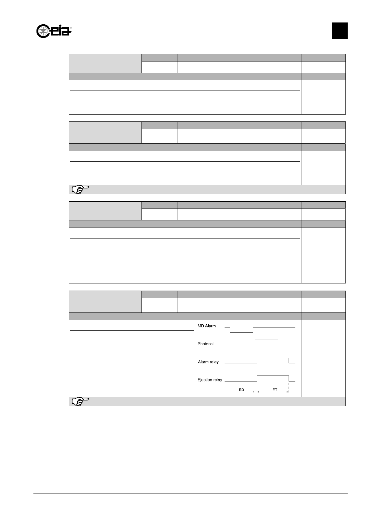
FI002K0021v1100UK – THS/21E and THS/21 Programming Manual
LOW PRESSURE inp
Description Models
Function type of the device connected to the "LOW PRESSURE" input
NC: Normally Closed; NO: Normally Open
Set NC or NO according to the output type of the connected sensor, in normal working condition.
Refer to the Installation manual for the electrical connection.
Analysis Mode
Description Models
Analysis mode of the received signal
HVI: Vibration immunity optimized for not dry product, detection sensitivity lower than STD
HSE: Sensitivity optimized for dry product, vibrations immunity lower than STD (not available on
THS/xx21E models).
Available only for some Detection modes. If not available, AM=STD.
Ejec.queue reset
Description Models
Reset of ejection queue in case of belt stop
QR=OFF: in case of belt stop during a product alarm, all the product between the probe entrance
(for EM=F) or photocell (for EM=S) and the ejector will be rejected when the belt is
started again.
QR=ON: in case of belt stop during a product alarm, the ejection queue is reset in case of belt
stop.
Reverse detect
Description Models
Reverse detection
Detection of lack of metal parts, with inverted
operation of both output relays (alarm and ejection).
This function requires a photocell (EM=S or SB) to be
mounted before or after the probe.
This function is normally used, for example, to detect
packages without closing clip.
Example with photocell at exit:
To reset the standard Metal Detection operation, set RD=OFF.
Remote Possible settings Standard setting Parameter
IAP
Remote Possible settings Standard setting Parameter
AM
Remote Possible settings Standard setting Parameter
QR
Remote Possible settings Standard setting Parameter
RD
NC / NO -
STD / HSE / HVI STD
ON / OFF OFF
ON / OFF OFF
PROGRAMMING PARAMETERS
Global
All models
Related to the
current product
All model except
THS/MN21
Global
All models
Available only with EM=S or F
Related to the
current product
All models
3
47
Page 48
FI002K0021v1100UK – THS/21E and THS/21 Programming Manual
3
PROGRAMMING PARAMETERS
Eject.act.if stop
Description Models
Ejector activation when belt stops
With EIS=ON the system has different behaviours, according to its configuration:
-
With Conveyor Control System or encoder: in case of a belt stop during an ejection, the ejector will
continue to be activated until the belt restart and then it will finish the ejection.
-
With FOLLOWING CONVEYOR Input used: in case of input deactivation during an ejection, the
ejector will continue to be activated until the input is activated again and then it will finish the
ejection.
With EIS=OFF the ejector is deactivated after 2 seconds from the belt stop during an ejection, or
from the FOLLOWING CONVEYOR.input deactivation.
EJECT RELAY logic
Description Models
Ejection relay logic
NC: In case of ejection, the relay switch to pin NC;
NO: In case of ejection, the relay switch to pin NO.
PREC CONV enable
Description Models
Enable “preceding conveyor” relay
Through the PREC_CONV relay (Preceding conveyor relay) the Metal Detector can control a device
connected in-line with it (for example a preceding conveyor system).
- With Conveyor Control System or encoder, if PC=ON the PREC_CONV relay is activated only
during the belt movement. If PC=OFF: the relay is always deactivated.
- With other systems, the application of this parameter has no effect.
FOLLW.CONV.enab
Description Models
Enable “following conveyor” input
Through the FOLLOWING CONVEYOR input (Following Conveyor) is possible to control the Metal
Detector from a device connected in-line with it (for example a following conveyor system).
If FC=ON the input status generates different behaviors for the Metal Detector, according to the
system configuration:
-
with Conveyor Control System: the Metal Detector belt is enabled to run only if the FOLLOWING
CONVEYOR input is active. The belt stops immediately in case of FOLLOWING CONVEYOR
input deactivation. See also RE.
-
with Control Power Box and without encoder: the Metal Detector stops incrementing the delay
counter for ejection activation in case the “following conveyor” input is not active. This functionality
can be used for example on a pipeline to stop the ejection activation delay in case the pump that
runs the liquid is stopped.
-
with Control Power Box and with encoder: the application of the parameter enable the belt speed
control (see also EA) only with the FOLLOWING CONVEYOR input enabled.
If FC=OFF: the system behavior is independent from the input status.
Remote Possible settings Standard setting Parameter
EIS
Remote Possible settings Standard setting Parameter
ERL
Remote Possible settings Standard setting Parameter
PC
Remote Possible settings Standard setting Parameter
FC
ON / OFF -
NO / NC NO
ON / OFF OFF
ON / OFF OFF
Global
All models
Not available with EM=B or SB
Global
All models
Global
All models
Global
All models
48
Page 49
Autom. restart
Description Models
Belt restart if there is “FOLLOWING CONVEYOR” input activation
If FC= OFF, the parameter has no effect;
If FC=ON:
- RE=OFF: if the belt is stopped by the “FOLLOWING CONVEYOR” input deactivation, when the
input is reactivated, the conveyor belt must be restarted manually
- RE=ON: if the belt is stopped by the “FOLLOWING CONVEYOR” input deactivation, when the
input is reactivated, the conveyor belt restarts automatically
pressed in the meantime.
green light ( ) flashes.
Test relay mode
Description Models
Test Request Relay functioning mode
It is possible to set the functioning mode for the TEST REQUEST relay:
- TREQ: the Relay is activated at the scheduled Test request, until the start of the Test execution;
- TACT: the Relay is activated only during the test execution.
Aux relay mode
Description Models
AUX Relay functioning mode
- ARM=0: AUX relay is used for the Quick Test; See parameter QCKT.
- ARM=N: AUX relay is activated when SC status include the value set on ARM.
See SC parameter for the possible values of N.
Stop Time
Description Models
Belt auto-stop time
The use of a Synchronization Photocell is requested: if no passage is detected for a time ST, with
the belt running, the conveyor belt stops automatically (N.B. No message is given).
Available only with Conveyor Control System
FI002K0021v1100UK – THS/21E and THS/21 Programming Manual
PROGRAMMING PARAMETERS
Remote Possible settings Standard setting Parameter
RE
When the belt is stopped because of the following conveyor input, the
Remote Possible settings Standard setting Parameter
TRM
Remote Possible settings Standard setting Parameter
ARM
Remote Possible settings Standard setting Parameter
ST
ON / OFF OFF
.
unless the STOP key has been
Available only with Conveyor Control System
TREQ / TACT TREQ
from 0 to N 0
0 – 99 min 0
3
Global
All models
Global
All models
Global
All models
Global
All models
49
Page 50
FI002K0021v1100UK – THS/21E and THS/21 Programming Manual
N
3
PROGRAMMING PARAMETERS
3.11.2 Motor config
List of parameters available under the Motor config submenu.
This menu is available only on models with Conveyor Control System.
All the following parameters refers to motor and inverter provided by CEIA.
In case of customer motor, read the motor label for the correct values
Nom.MotorVolt.
Description Models
Nominal motor voltage, from rating plate
This parameter is adjustable only with the motor stopped.
On CEIA integrated systems the value is already set to ensure the correct functioning of the system itself
Nom.MotorCurr.
Description Models
Nominal motor current, from rating plate
If set to 0.00, the motor overload protection is disabled.
This parameter is adjustable only with the motor stopped.
On CEIA integrated systems the value is already set to ensure the correct functioning of the system itself
Nom.MotorPower
Description Models
Nominal motor power, from rating plate
This parameter is adjustable only with the motor stopped.
On CEIA integrated systems the value is already set to ensure the correct functioning of the system itself
Nom.MotorCosPhi
Description Models
om.MotorVolt.
Nom.MotorCurr.
Nom.MotorPower
Nom.MotorCosPhi
Nom.MotorEffic
Nom.MotorFreq.
Nom.Motor.Speed
Max inv. freq.
Acceler. Time
Deceler. Time
Flying start
Inv.PulseFreq.
Inv.BaseFreq.
ResetInv.ToDefault
Remote Possible settings Standard setting Parameter
NMV
70 – 230 V 230
Global
All models
Available only with Conveyor Control System
Remote Possible settings Standard setting Parameter
NMC
0.00 – 9.00 A -
Global
All models
Available only with Conveyor Control System
Remote Possible settings Standard setting Parameter
NMP
0.00 – 10.00 kW -
Global
All models
Available only on some versions and only with Conveyor Control System
Remote Possible settings Standard setting Parameter
NMCP
0.000 - 1.000 -
Global
Nominal motor power factor (cos), from rating plate
This parameter is adjustable only with the motor stopped.
All models
Available only on some versions and only with Conveyor Control System
On CEIA integrated systems the value is already set to ensure the correct functioning of the system itself
Remote Possible settings Standard setting Parameter
Nom.MotorEffic
NME
0.00 – 0.99 -
Global
Description Models
Nominal motor efficiency, from rating plate
This parameter is adjustable only with the motor stopped.
All models
Available only on some versions and only with Conveyor Control System
On CEIA integrated systems the value is already set to ensure the correct functioning of the system itself
50
Page 51
FI002K0021v1100UK – THS/21E and THS/21 Programming Manual
Nom.MotorFreq.
Description Models
Nominal motor frequency, from rating plate
This parameter is adjustable only with the motor stopped.
Available only with Conveyor Control System
On CEIA integrated systems the value is already set to ensure the correct functioning of the system itself
Nom.Motor.Speed
Description Models
Nominal motor speed, from rating plate
This parameter is adjustable only with the motor stopped.
Available only with Conveyor Control System
On CEIA integrated systems the value is already set to ensure the correct functioning of the system itself
Max inv. freq.
Description Models
Maximum output frequency of the inverter
This parameter is adjustable only with the motor stopped.
Available only with Conveyor Control System
On CEIA integrated systems the value is already set to ensure the correct functioning of the system itself
Acceler. Time
Description Models
Motor acceleration time
This parameter is adjustable only with the motor stopped.
Deceler. Time
Description Models
Motor deceleration time
This parameter is adjustable only with the motor stopped.
Flying start
Description Models
Flying start
Set to ON only in case of motor interferences to the THS/MN21 probe.
This parameter is adjustable only with the motor stopped.
Available only with Conveyor Control System
Remote Possible settings Standard setting Parameter
NMF
Remote Possible settings Standard setting Parameter
NMS
Remote Possible settings Standard setting Parameter
MI
Remote Possible settings Standard setting Parameter
ACCT
Remote Possible settings Standard setting Parameter
DECT
Available only with Conveyor Control System
Remote Possible settings Standard setting Parameter
IFLY
12 – 99,00 Hz -
0 – 40000 rpm -
60 – 100 Hz -
0.00 – 99.00 s -
Available only with Conveyor Control System
0.00 – 99.00 s -
OFF / ON -
PROGRAMMING PARAMETERS
Global
All models
Global
All models
Global
All models
Global
All models
Global
All models
Global
All models
3
51
Page 52
FI002K0021v1100UK – THS/21E and THS/21 Programming Manual
3
PROGRAMMING PARAMETERS
Remote Possible settings Standard setting Parameter
Inv.PulseFreq.
IPF
Description Models
PWM frequency
This parameter is adjustable only with the motor stopped.
Available only with Conveyor Control System
Inv.BaseFreq.
Remote Possible settings Standard setting Parameter
IBF
Description Models
Motor frequency [Hz]
This parameter is adjustable only with the motor stopped.
Available only on some versions and only with Conveyor Control System
ResetInv.ToDefault
Remote Possible settings Standard setting Parameter
IRST
Description Models
Reset inverter parameters to default
This command reset all inverter internal parameters (not listed here) to the default values, optimized
for THS. A confirmation will be requested. This command is selectable only with the motor stopped.
RS232 BaudRate
Remote Possible settings Standard setting Parameter
BR
Description Models
Setting of the RS232 BaudRate
auxRS232B.Rate
Remote Possible settings Standard setting Parameter
AUBR
Description Models
Setting of the auxiliary RS232 BaudRate
DTR protocol
Remote Possible settings Standard setting Parameter
DT
Description Models
DTR protocol
Use of DTR (Data Terminal Ready) line to communicate with a serial printer.
DT=N: line not used;
DT=H: line used, in handshake mode, as active if high. The Metal Detector stops sending data to
the serial port, in case the line is not pulled up.
Bounce time
Remote Possible settings Standard setting Parameter
BT
Description Models
Setting of the minimum activation time for fast inputs
Minimum activation time for a “fast” input (all inputs and the photocells), to be considered active.
2, 4, 6, 8, 10,
12, 14, 16 kHz
50 / 60 Hz -
- -
Available only with Conveyor Control System
9600 / 57600 bps 57600
9600 / 57600 bps -
N / H N
0,001 – 0,200 s 0,005
-
Global
All models
Global
All models
Global
All models
Global
All models
Global
All models
Global
All models
Global
All models
52
Page 53
FI002K0021v1100UK – THS/21E and THS/21 Programming Manual
Wind
Bounce t. slow
Description Models
Setting of the minimum activation time for slow inputs
Minimum activation time for a “slow” input (control keys and emergency buttons), to be considered
active.
Centre belt time
Description Models
Retractable flat belt centering time delay
Used on some models of retractable conveyors with flat belt, equipped with centering pistons and
photocells; in this systems:
- the activation of a centering photocell, activates the relative centering piston
- the deactivation of a centering photocell, deactivates the relative centering piston with a delay of
CBT (the delay count will be reset in case of re-activation of the photocell within CBT time).
Set CBT=0 to deactivate the centering.
Remote Possible settings Standard setting Parameter
BTS
Remote Possible settings Standard setting Parameter
CBT
0,001 – 0,200 s 0,05
0 – 60 s 0
3.12 Barcode reader
List of parameters available under the Barcode reader menu.
This menu is available only if the use of a barcode reader has been
enabled (contact CEIA).
Window start
Description Models
First of product identification characters
First character of series used to identify the product within the code.
Example: If on an EAN13 code (code length 13 digits) we want to ignore the first 3 digits, we must
set WS=4 and WE=13. In this case code 8004040090011 is considered the same of code
9114040090011.
Available only with barcode reader enabled
Window end
Description Models
Last of product identification characters
Last character of series used to identify the product within the code.
Example: If on an EAN13 code (code length 13 digits) we want to ignore the last 2 digits, we must
set WS=1 and WE=11. In this case code 8004040090011 is considered the same of code
8004040090022.
Available only with barcode reader enabled
Remote Possible settings Standard setting Parameter
WS
Remote Possible settings Standard setting Parameter
WE
1 - 48 -
1 - 48 -
PROGRAMMING PARAMETERS
Global
All models
Global
All models
ow start
Window end
Learn code
Barc-MD dist.
No code ejection
Global
All models
Global
All models
3
53
Page 54
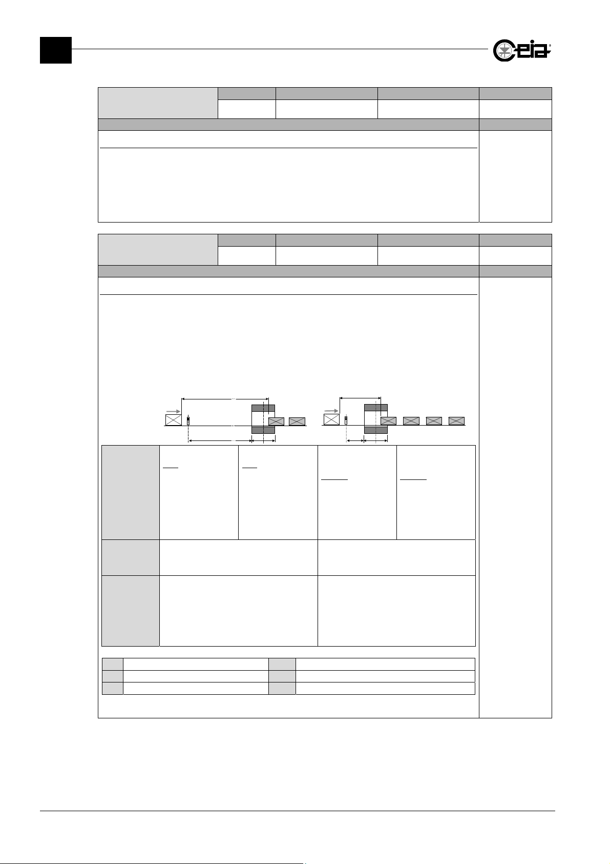
FI002K0021v1100UK – THS/21E and THS/21 Programming Manual
3
PROGRAMMING PARAMETERS
Remote Possible settings Standard setting Parameter
Learn code
LC
ON / OFF OFF
Description Models
Activation of code/product association phase
Command which allows a code to be associated with a product. When activated (LC=ON), the
message “Pass Code” appears on the display. After the barcode is passed in front of the reader, the
message “ENTER to confirm” and the code read both appear on the display. Press ENTER to
associate the code read with the current product, press PROG key to cancel the operation. if one of
the arrow keys is pressed, a new request to pass the barcode in front of the reader is made.
Available only with barcode reader enabled
Remote Possible settings Standard setting Parameter
Barc-MD dist.
BD
300 – 5000 mm -
Description Models
Distance between reading point and antenna
The reader is mounted upstream of the probe in order to read a code stamped on the package. If the
code is recognised, the reader sends a command to the Metal Detector to select the relevant
product type. The time required by the THS to process the barcode is usually insignificant, but
becomes important if the band or the detection mode is changed due to a modification in the type of
product. When the Metal Detector receives the signal to change product type, an internal adjustment
procedure is activated the length of which determines the minimum distance between two packages
with different codes, that is to say containing different products.
Model /
Event
THS/xxMS21
change of
with
detection mode
(DM) between one
product and the
other
Dp
Dsbr
THS/21E-3F
with change of
band (BA)
between one
product and the
other
S
N
L
THS/xx21 or
THS/xxMS21
without
detection mode
(DM) between one
product and the
BR
other
Distance
between the
L + 3000 mm Dp L + 300 mm
D
p
packs
Distance
between the
barcode
reader and
D
3000 mm D
sbr
sbr
the THS/21
probe
S Metal Detector probe L Length of probe
N Conveyor belt Dsbr
Distance THS probe-barcode rea er
BR Barcode Reader Dp Distance between packs of different products
Available only with barcode reader enabled and EM=S or SB
Dp
S
BR
D
sbr
L
change of
300 mm
THS/21E or
THS/21E-3F
without
change of
band (BA
parameter)
between one
product and the
other
Global
All models
Global
N
All models
54
Page 55
Output
Al
L
PHOTOCELL i
H
No code ejection
Description Models
Ejection of packs with wrong code
When activated, the packages without barcodes or with invalid barcodes are ejected. If deactivated,
there is no action.
3.13 I/O Status
FI002K0021v1100UK – THS/21E and THS/21 Programming Manual
PROGRAMMING PARAMETERS
Remote Possible settings Standard setting Parameter
NE
ON / OFF OFF
Global
All models
Available only with barcode reader enabled and EM=S or SB
In order to function, a photocell for synchronization of the packs must be installed. This photocell can be
installed before or after the THS probe; HOWEVER, IT MUST BE INSTALLED AFTER THE BARCODE
READER.
3
This menu shows, in real time, the list of input and output lines with
indication of their status, together with the value of the measures
performed by and variables set on the Metal Detector.
The status display is subdivided into practical submenus.
3.13.1 Outputs
This submenu shows, in real time, the list of output lines with
indication of their status. (L: not active, H: Active).
Selecting an output and pressing the E key, it is possible to manually
change each state pressing arrow keys. Pressing again the E key, the
output is deselect and return to the previous state.
3.13.2 Inputs
This submenu shows, in real time, the list of input lines with indication
of their logic level. (L: not active, H: Active).
The list of shown output lines may vary depending on the Metal Detector model.
The list of shown input lines may vary depending on the Metal Detector model.
Inputs
Measures
Variables
Eject relay L
Eject NO L
Eject NC L
PREC CONV relay L
TEST REQ.relay L
READY relay H
AUX relay L
INVERTER relay L
MOTOR FAULT light L
RUNNING light L
RED lamp L
YELLOW lamp L
BLUE lamp L
Ext.buzzer L
EJECT.CONF.input L
EJECT CHECK in H
RESET in L
INHIBITION in L
FOLLW.CONV.input L
BIN FULL input L
BIN ABSENT input L
LOW PRESSURE inp L
AUX1 input L
EJ.POSIT.CHK.in L
START button in L
STOP button in L
UP button in L
DOWN button in L
RESET button in L
ENCODER in MOTOR FAULT in L
EMGCY sec1 H
EMGCY sec2 H
EMGCY sec3 H
J16.3-4 H
EMGCY RELAY H
DTR in L
Vout CHECK H
Vin CHECK H
DIP 1 H
DIP 2 H
DIP 3 H
Show Barcode Rdr In H
s
arm relay
nput
55
Page 56
FI002K0021v1100UK – THS/21E and THS/21 Programming Manual
S
Z1
0
3
PROGRAMMING PARAMETERS
3.13.3 Measures
This submenu shows a list of measures performed in real time by the
Metal Detector. This can be useful during Technical Assistance.
The list of shown measures may vary depending on the Metal Detector model.
3.13.4 Variables
This menu is not available on THS/xx21E models.
This submenu shows a list of variables related to the current product.
These variables are set automatically during the Autolearn
procedure.
Changing manually these values can cause an incorrect operation of the Metal Detector! In this case, repeat the
Autolearn for the current product.
The list of shown variables may vary depending on the
Metal Detector model and settings.
peed
Motor curr.
Motor volt V11
ALM supply V1 24.0
ALM supply V2 +15.7
ALM supply V3 -15.9
SCD supply V4 1.6
Vtx+ V5 13.5
Vtx- V6 13.3
V71 0.0
V72 0.0
V81 3.5
V82 0.2
Vprobe V9 15.4
ALMsupply V12 5.8
Itx+ I5 0.283
Itx- I6 0.270
Internal temp. +45
Ej.op.time 0.000
Z2 0
Z3 0
56
Page 57
FI002K0021v1100UK – THS/21E and THS/21 Programming Manual
Phot
lt
3.14 Diagnosis managem.
List of parameters available under the Diagnosis managem. menu.
Photocell fault
Description Models
Enabling of Synchronization and Ejection Check photocells diagnosis
Enabling / disabling of the diagnosis for the Synchronization and Ejection Check photocells.
See SPMA, CPMA and PAT parameters.
Sync.max.activ
Description Models
Maximum continuous activation of the Synchronization photocell
Set SPMA to a maximum allowed distance (in millimetres) ran from the belt with continuous
Synchronization photocell activation: if exceeded, the “Sync Photocell” Fault is activated.
Set SPMA=0 to disable this diagnosis. Anyway, this diagnosis is anyway disabled with PA=OFF.
Chck.max.activ
Description Models
Maximum continuous activation of the Ejection Check photocell
Set CPMA to a maximum allowed distance (in millimetres) ran from the belt with continuous Ejection
Check photocell activation: if exceeded, the “Ejection Check Photocell” Fault is activated.
Set CPMA=0 to disable this diagnosis. Anyway, this diagnosis is anyway disabled with PA=OFF.
Phot.fau.thres
Description Models
Photocell fault activation threshold
If PAT > 0, the Synchronization and Ejection Check photocells activations are counted during the
belt movement (or with FOLLOWING CONVEYOR Input activated, if used) without ejection in
progress.
If the difference between photocells activations reaches PAT value, the Metal Detector activates the
Fault status related to the photocell with less activations.
Set PAT=0 to disable this diagnosis. Anyway, this diagnosis is anyway disabled if PA=OFF.
PAT=1 is equivalent to PAT=2.
Remote Possible settings Standard setting Parameter
PA
ON / OFF OFF
Remote Possible settings Standard setting Parameter
SPMA
0 – 60000 mm 0
Remote Possible settings Standard setting Parameter
CPMA
0 – 60000 mm 0
Remote Possible settings Standard setting Parameter
PAT
0 – 10000 -
PROGRAMMING PARAMETERS
ocell fau
Sync.max.activ
Chck.max.activ
Phot.fau.thres
Bin full
Bin full delay
Bin absent
Bin absent delay
Bin with lock
Unlock bin time
Air pressure low
Low press. delay
Eject confirmat.
Confirm time
Eject.check
Ej.check accur.
Pho.diag.if stop
Ejector pos.chk
Ej.pos.chk delay
Encoder check
Test time out
Test failed
Event buf. full
Login restrict.
Al.rate period
Al.rate threshold
Ej. max extent
Ejec.on fault
Probe fault reset
Global
All models
Global
All models
Global
All models
Global
All models
3
57
Page 58
FI002K0021v1100UK – THS/21E and THS/21 Programming Manual
3
PROGRAMMING PARAMETERS
Bin full
Description Models
Bin Full fault activation
Set LF = ON to enable the “Bin Full” Fault activation in case of BIN FULL Input activated for a time
longer than LFD delay. The system is automatically reset by removing the fault cause.
See also IL and LFD parameters.
With LF=CEON, the “Bin full” fault is activated when the EJECT.CONFIRMATION input is activated
(used when the ejection confirmation sensor is used to check the bin full condition too)
Bin full delay
Description Models
Bin Full fault delay
If the BIN FULL input is activated continuously for LFD time, the relative Fault status is activated.
Bin absent
Description Models
Bin Absent fault activation
Set LA = ON to enable the “Bin Absent” Fault activation in case of BIN ABSENT input activated for a
time longer than LAD delay. The system is automatically reset by removing the fault cause.
See also IA and LAD parameters.
Bin absent delay
Description Models
Bin Absent fault delay
If the BIN ABSENT input is activated continuously for LAD time, the relative Fault status is activated.
In case of a bin fitted with electro-mechanical locking device, set LAD to a value that allows a correct
emptying procedure.
Bin with lock
Description Models
Bin control by electro-mechanical locking device
With this parameter set to ON, opening the bin with electric lock is allowed only by entering the
Programming phase and using the command Unlock bin. The electro-mechanical locking device
will be then open for UBT time.
Every bin unlocking is registered in the events log.
Unlock bin time
Description Models
Unlock bin time
Remote Possible settings Standard setting Parameter
LF
Remote Possible settings Standard setting Parameter
LFD
Remote Possible settings Standard setting Parameter
LA
Remote Possible settings Standard setting Parameter
LAD
Remote Possible settings Standard setting Parameter
BWL
Remote Possible settings Standard setting Parameter
UBT
ON / OFF / CEON -
00:00 – 59:59
mm:ss
ON / OFF -
00:00 – 59:59
mm:ss
ON / OFF OFF
0 – 30 s 0
Global
All models
-
-
Global
All models
Global
All models
Global
All models
Global
All models
Global
All models
58
Page 59
FI002K0021v1100UK – THS/21E and THS/21 Programming Manual
PROGRAMMING PARAMETERS
Air pressure low
Description Models
Low Pressure fault activation
Set AP = ON to enable the “Low Pressure” Fault activation in case of LOW PRESSURE Input
activated for a time longer than APDL delay. The system is automatically reset by removing the fault
cause.
See also IAP and APDL parameters.
Low press. delay
Description Models
Low Pressure fault delay
If the LOW PRESSURE input is activated continuously for APDL time, the relative Fault status is
activated.
Eject confirmat.
Description Models
Enabling of the ejection confirmation
Set CE = ON to enable the control of the ejection confirmation. After the ejector activation, if the
EJECT CONFIRM Input is not activated within CT time, the Fault “Ejection not confirmed” is
activated (for example, in case of a contaminated pack not rejected correctly into the storage bin, or
with the ejector not correctly activated). Check the cause and reset the Fault.
If Ejection Position Check sensor is not used (EPC=OFF), this control enable also the activation of
the Fault “Ejection system jam” in case of Ejection Confirmation Input activation without ejection
before (for example, in case of a pack blocked, during the transit, in front of the Ejection
Confirmation sensor, or with the ejector stuck in ejection position). Removing the cause, the Metal
Detector reset automatically the Fault.
If EPC=ON, this control enables also the activation of the fault “Eject.out of order”, in case the
ejector is not correctly positioned.
Confirm time
Description Models
Confirm ejection time
With the Ejection Confirmation activated (CE=ON), CT represents the maximum allowed delay time
for the Ejection Confirmation Input to be activated, from the Ejection activation. See also CE
parameter.
Eject.check
Description Models
Ejection check functionality
With ECK=ON, the Ejection Check Photocell (EJECT CHECK Input) checks that, during an ejection,
the belt area cleared by the ejector is completely empty, to avoid possible contaminated pack
transits without ejection.
Set ECK=OFF to disable the control. See also ECKA parameter.
If CE=ON, it is possible to view the last opening time, elapsed from opening command and Ejection
Confirmation input activation, directly on I/O Status > Measures > Ej.op.time.
Set CT at a value not lower than the real opening time.
59
Remote Possible settings Standard setting Parameter
AP
Remote Possible settings Standard setting Parameter
APDL
Remote Possible settings Standard setting Parameter
CE
Remote Possible settings Standard setting Parameter
CT
Remote Possible settings Standard setting Parameter
ECK
ON / OFF -
0 – 60 s -
ON / OFF -
Available only with EM=F,S or FS.
0,01 – 60,00 s -
ON – OFF -
Available only with EM=S or FS
Global
All models
Global
All models
Global
All models
Global
All models
Global
All models
3
Page 60
FI002K0021v1100UK – THS/21E and THS/21 Programming Manual
3
PROGRAMMING PARAMETERS
Ej.check accur.
Description Models
Accuracy of the ejection check functionality
Setting ECKA:
EM=FS: the area to be checked is equal to the area cleared by the ejector, reduced of ECKA value
on both sides.
EM=S: the area to be checked is equal to the pack length, reduced of ECKA value on both sides.
Pho.diag.if stop
Description Models
Photocell diagnosis with belt stop
If PDIS is set to ON, the diagnosis for the Bin Full, Bin Absent and Low Pressure inputs are
performed also when the conveyor belt is stop (or with Following Conveyor Input not active, if used).
Ejector pos.chk
Description Models
Activation of the Ejector Position Check
This control, together with CE=ON, enables the activation of the fault “Ejector out of order”, in case
the ejector is not correctly positioned or not correctly re-positioned within EPCD time from the ejector
activation.
Ej.pos.chk delay
Description Models
Setting of the ejector position verification delay
Set EPCD to the maximum time allowed (from the activation command) for the ejector to return
correctly in the rest position. See also EPC parameter.
Set EPCD to a value not lower than the real ejector opening and closing time.
If EPC=ON, it is possible to view the last activation and deactivation time (
activation command to EJECT.CONFIRMATION input activation;
command to EJECTOR POSITION CHECK input activation), in
Encoder check
Description Models
Activation of the encoder check functionality
If an encoder is used (KE > 0), set EA=ON to enable the encoder belt speed check. This control
depends on the system configuration:
-
With Conveyor Control System: After 10 seconds from the conveyor belt starting, if the speed read
by the encoder is lower than 0.7 BL or higher than 1.3 BM, the Fault “Encoder Frequency too low”
or the Fault “Encoder Frequency too high” is activated respectively. Remove the cause and reset
the Fault.
-
With Control Power Box: After 10 seconds from the conveyor belt starting, if the speed read by the
encoder is lower than BL or higher than BM, the Fault “Encoder Frequency too low” or the Fault
“Encoder Frequency too high” is activated respectively. Remove the cause and reset the Fault.
Con Control Power Box, è richiesta la connessione dell’ingresso FOLLOWING CONVEYOR e l’attivazione
del parametro FC, altrimenti il controllo della velocità viene comunque sempre effettuato indipendentemente
dallo stato del nastro.
Remote Possible settings Standard setting Parameter
ECKA
Remote Possible settings Standard setting Parameter
PDIS
Remote Possible settings Standard setting Parameter
EPC
Remote Possible settings Standard setting Parameter
EPCD
Remote Possible settings Standard setting Parameter
EA
2 – 250 mm -
ON / OFF -
ON – OFF -
1,00 – 60,00 s -
ON – OFF -
Available only with EM=S or FS
Ej.op.time
Ej.cl.time
I/O Status > Measures
, elapsed from deactivation
, elapsed from
.
Global
All models
Global
All models
Global
All models
Global
All models
Global
All models
60
Page 61
FI002K0021v1100UK – THS/21E and THS/21 Programming Manual
Test time out
Description Models
Activation of fault status if maximum time for Test expires
Set FT=ON to enable the Fault ”Test Timeout” activation in case of a scheduled Test not started
within the maximum time (TD or FTD).
In case of Test timeout, it is required to reset the Fault and to execute the Test.
See also STM parameter.
Test failed
Description Models
Activation of fault status if a Test fails
Set FF=ON to enable the Fault “Test Failed” activation in case of Test failure.
In case of Test failure, it is possible to reset the Fault (if STM=OFF) or it is required to perform also
again and successfully the Test (if STM=ON).
See also STM parameter.
Event buf. full
Description Models
Fault activation in case of memory buffer full
The Events buffer memory contains always the last 1000 (21E series) or 10000 (21 series) or
100000 (with IXC card) occurred events. When the events buffer is 100%, the new events overwrite
the oldest ones.
Set FB=ON to avoid possible overwriting of event not yet printed: when the events buffer memory,
not printed, is at 90% (equivalent to 900 events on 21E series, 9000 on 21 series or 90000 with IXC
card), the Fault “Event Buffer Full” is activated. In this case it is required to print last events (PL) and
erase the print events (EV). Events are not immediately erased, but simply they are available to be
overwritten by future events.
With IXC card, save the last events with the command “Save last events”, then erase them with the
command “Empty last events”.
Set FB=OFF to disable this control. See also PL and EV parameters.
Login restrict.
Description Models
Activation of restricted login after three failed attempts
Set FLR=ON to enable the control about possible programming unauthorized access attempts: if
enabled, in case of three consecutive failed attempts the “Login restricted” Fault is activated.
Refer to paragraph 2.4.4 to reset this fault.
Al.rate period
Description Models
Setting of alarm rate period
See parameter ART.
Remote Possible settings Standard setting Parameter
FT
Remote Possible settings Standard setting Parameter
FF
Remote Possible settings Standard setting Parameter
FB
Remote Possible settings Standard setting Parameter
FLR
Remote Possible settings Standard setting Parameter
ARP
ON / OFF ON
ON / OFF ON
ON / OFF OFF
ON / OFF ON
0 – 60 min 0
PROGRAMMING PARAMETERS
Global
All models
Global
All models
Global
All models
Global
All models
Global
All models
3
61
Page 62
FI002K0021v1100UK – THS/21E and THS/21 Programming Manual
3
PROGRAMMING PARAMETERS
Al.rate threshold
Remote Possible settings Standard setting Parameter
ART
Description Models
Setting of alarm rate threshold
Set ART > 0 to enable the control of the Alarms number, according to ARP parameter:
ARP=0: if the number of current product Alarms (CA) reaches ART value, the Fault “Too many
Alarms” is activated. Reset the Product Alarm counter to Reset the Fault.
ARP>0: in case of ART Alarms during ARP time, the Fault “Too many Alarms” is activated. Reset
the Fault.
Set ART=0 to disable this control. See also CA parameter.
Ej. max extent
Remote Possible settings Standard setting Parameter
EMEX
Description Models
Maximum continuous ejection extension
With Conveyor Control System, set EMEX to the maximum acceptable covered distance with the
ejector activated continuously due to long Alarm.
With Control Power Box, set EMEX to the maximum acceptable time with ejector activated
continuously due to long Alarm (as 0.06 EMEX/BS seconds).
If the ejection is activated for an extension higher than this limit, the Fault “Too many alarms” is
activated. Reset the Fault for system recovery.
Set EMEX=0 to disable this control.
Ejec.on fault
Remote Possible settings Standard setting Parameter
EF
Description Models
Ejection on fault
Set EF=ON to activate the ejection in case of Faults (except “Bin Full”, ”Bin Absent”, ”Low pressure”)
with moving belt. Reset the fault to deactivate the ejector.
With Conveyor Control System and SF=ON, the parameter has no effect.
Probe fault reset
Remote Possible settings Standard setting Parameter
PFR
Description Models
Automatic probe fault reset
If set to MAN, the system needs to be manually reset for each probe fault, even when the fault is
automatically solved by the system itself.
0 – 250 0
0 – 60000 mm 0
Available only with EM=F or FS
ON / OFF ON
MAN / AUT AUT
Global
All models
Global
All models
Global
All models
Global
All models
62
Page 63
FExtest
Fail
t
3.15 MD Test
List of commands available under the MD Test menu.
FE test
Description Models
Activation of the test with Ferrous metal Test Sample
Select the test and press E key to start it. If FD>0, the diameter of the Ferrous Test Sample sphere
to be used is shown on display. Pass the sample within 1 minute.
For the test procedure and outcomes, see Functionality tests section of the Instructions manual.
See also FD,STM,SAC and FF parameters.
NFE test
Description Models
Activation of the test with Not Magnetic metal Test Sample
Select the test and press E key to start it. If ND>0, the diameter of the Not Magnetic Test Sample
sphere to be used is shown on display. Pass the sample within 1 minute.
For the test procedure and outcomes, see Functionality tests section of the Instructions manual.
See also ND,STM,SAC and FF parameters.
SS test
Description Models
Activation of the test with Stainless Steel Test Sample
Select the test and press E key to start it. If SD>0, the diameter of the Stainless Steel Test Sample
sphere to be used is shown on display. Pass the sample within 1 minute.
For the test procedure and outcomes, see Functionality tests section of the Instructions manual.
See also SD,STM,SAC and FF parameters.
FI002K0021v1100UK – THS/21E and THS/21 Programming Manual
PROGRAMMING PARAMETERS
NFExtest
SSxtestx
Remote Possible settings Standard setting Parameter
-
Remote Possible settings Standard setting Parameter
-
Remote Possible settings Standard setting Parameter
-
- -
- -
- -
x
Related to the
current product
All models
Global
All models
Global
All models
3
3.16 Fail-safe test
List of commands available under the Fail-safe test menu.
Fail-safe test
Description Models
Activation of the Fail-Safe test
An Ejection Confirmation photocell is requested. This test disables the ejector during its execution, in
order to check if in case of ejector malfunctions the system allows to recover correctly a
contaminated pack not rejected.
Press E to execute the Fail Safe Test and pass a pack causing Alarm (e.g. a pack with a Test
sample); after CT time, the “Eject not confirm” Fault is activated and the Fail Safe Test finishes.
Verify the possibility to recover the contaminated pack, otherwise adjust the current settings (for
example: CT, PC, SF)
Available only with CE=ON
63
-safe tes
Remote Possible settings Standard setting Parameter
-
- -
Global
All models
Page 64
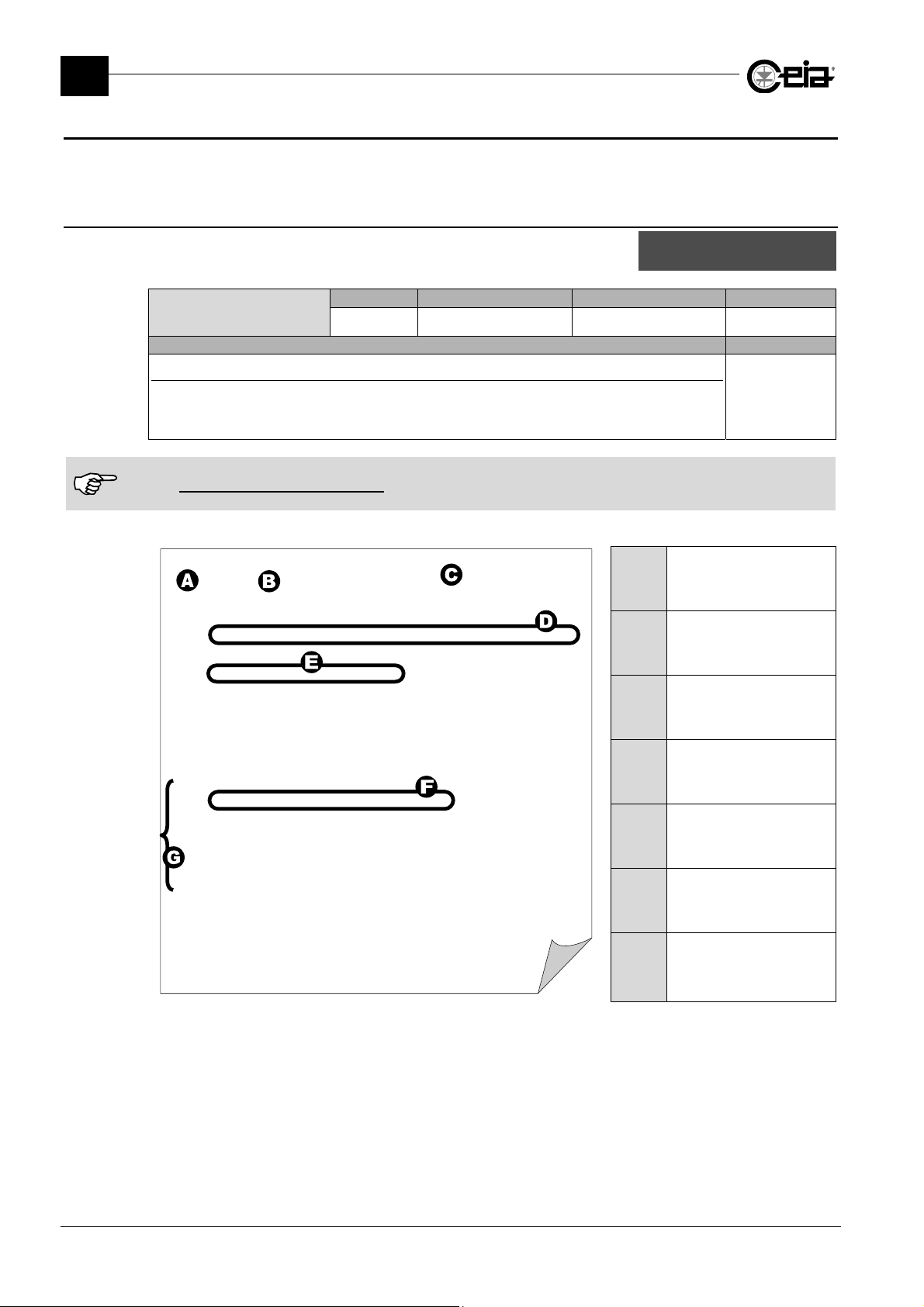
FI002K0021v1100UK – THS/21E and THS/21 Programming Manual
Print
3
PROGRAMMING PARAMETERS
3.17 Print
The list of commands available under the Print menu changes accordingly with the presence of an
IXC card.
3.17.1 With no IXC card installed
List of commands available under the Print menu, when no IXC card
is installed.
Print last events
Description Models
Print last events list
This command allows to physically print (using a serial printer, see DTR) or view (using remote
programming software, e.g. Ceia MDScope or Hyperterminal
“erasing” operation (by EV command). See also EV and DTR.
The events buffer stores until 10000 (THS 21 series) or 1000 (THS 21E series) events occurred, ordered by date and
time. It is not possible to empty its content. When it is full, the new following events will overwrite the oldest ones.
Set FB=ON (see FB parameter) to avoid any possible overwriting of not yet printed events.
Here below an example of a report:
[000] 11/07/03 - 9:01:27 Metal Detector Off
-024027-
[001] 11/07/03 - 9:01:32 Metal Detector On
-185128-
[005] 11/07/03 - 9:02:01 LogIn (LOCAL)
Name: JOHN Surname: SMITH Descrip.: ADMINISTR
-138062-
[009] 11/07/03 - 9:02:10 Product Modified: PROD01
Sensitivity 280 -> 278
Name: JOHN Surname: SMITH Descrip.: ADMINISTR
-185191-
[006] 11/07/03 - 9:02:11 LogOut (LOCAL)
Name: JOHN Surname: SMITH Descrip.: ADMINISTR
-212118-
[005] 11/07/03 - 9:02:49 LogIn (LOCAL)
Name: ALAN Surname: BLACK Descrip.: SUPERVISR
-143028-
[012] 11/07/03 - 9:02:53 Alarm
Sensitivity: 278 Amplitude: 23.9 dB
-051038-
[015] 11/07/03 - 9:02:59 Test Passed
Prod.: PROD01 Fe diameter: 1.00
Name: ALAN Surname: BLACK Descrip.: SUPERVISR
-177205-
[013] 11/07/03 - 9:03:00 Ejection: PROD01
-076195-
[006] 11/07/03 - 9:03:02 LogOut (LOCAL)
Name: ALAN Surname: BLACK Descrip.: SUPERVISR
-096201-
+169130+
#
last events
Print all events
Erase printed ev
Remote Possible settings Standard setting Parameter
PL
- -
®
) all the events occurred since the last
A
B
C
D
E
F
G
Event code
Date and Time
Event description
User data
Parameter change
Alarm data
Test performed using a
ferrous sample
Global
All models
64
Page 65
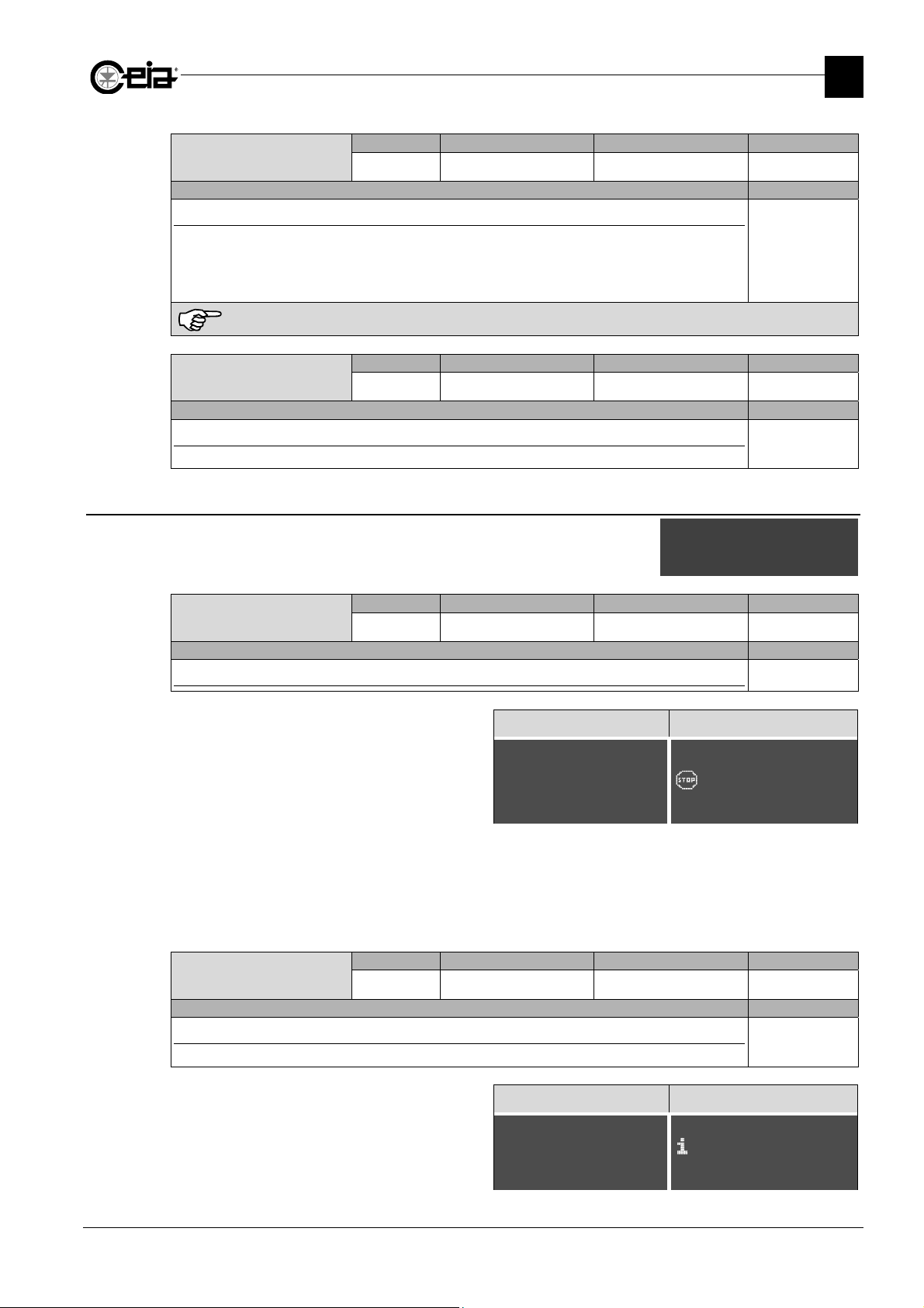
S
\\\\\\\\\
]
Erase printed ev
Description Models
Erasing of printed events
This command confirm the events printed with PL, from the last EV command and consequently
make available the corresponding memory space for next events recordings.
It is a good practice to use EV command only in case the events printed by PL command have been
opportunely saved (physically printed or saved in a file).
This command does not physically erase the Events buffer.
Print all events
Description Models
Print all events
This command prints all the events stored in the buffer.
3.17.2 With IXC card installed
List of commands available under the Print submenu, when an IXC
card is installed (IXC=ON).
Save last events
Description Models
Data saving of events occurred since the previous “Empty last events”
If an USB key is not already inserted on the Metal
Detector USB plug, a message will be shown at the
operation start.
FI002K0021v1100UK – THS/21E and THS/21 Programming Manual
PROGRAMMING PARAMETERS
Remote Possible settings Standard setting Parameter
EV
- -
Global
All models
Remote Possible settings Standard setting Parameter
PB
- -
Global
All models
ave last events
Empty last events
Save events
Remote Possible settings Standard setting Parameter
-
- - Global
All models
THS/xx21E THS/xx21
=====================
Insert USB memory
Press P to exit
---------------------
[\\\\\\\\\\\\\\\\\\\]
Insert USB memory
Press P to exit
{|||||||||||||||||||}
3
The Metal Detector events are saved as:
:/Ceia/SNxxxxxxxxxxx/Log/xxxxxxxxxxx_LAST_EVENTS_YYYYMMDD_HHMM.LOG
where xxxxxxxxxxx is the Metal Detector serial number, YYYYMMDD_HHMM is the datestamp.
Remote Possible settings Standard setting Parameter
Empty last events
-
- -
Global
Description Models
Data empty of events, already saved with the previous “Save last events”
All models
At the end of the operation, the message “Done” is
shown.
=====================
Done
---------------------
THS/xx21E THS/xx21
[\\\\\\\\\\
Done
{|||||||||||||||||||}
65
Page 66
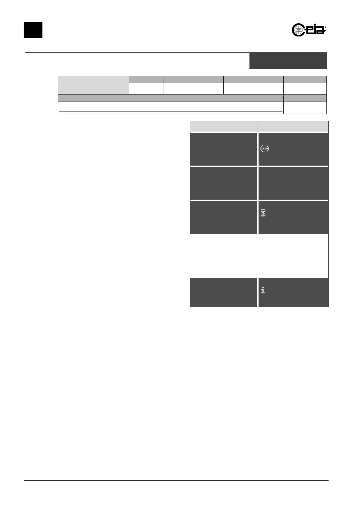
FI002K0021v1100UK – THS/21E and THS/21 Programming Manual
S
F
11
F
11
\\\\\\\
]
\\\\\\\
]
3
PROGRAMMING PARAMETERS
3.17.2.1 Save events
List of commands available under the Save events submenu.
Save from-to
Description Models
Data saving of events occurred in a time period
If an USB key is not already inserted on the Metal Detector
USB plug, a message will be shown at the operation start.
ave from-to
Save all events
Remote Possible settings Standard setting Parameter
-
- - Global
All models
THS/xx21E THS/xx21
=====================
Insert USB memory
Press P to exit
---------------------
[\\\\\\\\\\\\\\\\\\\]
Insert USB memory
Press P to exit
{|||||||||||||||||||}
Select the time interval, then select Save and press E to
save the data of events occurred in that period.
In presence of several events, a message will ask to wait.
rom 14:17 06/04/
to 17:30 06/04/11
Save *
=====================
WAIT
CAN TAKE MINUTES
---------------------
The Metal Detector events are saved as:
:/Ceia/SNxxxxxxxxxxx/Log/xxxxxxxxxxx_YYYYMMDD_HHMM-yyyymmdd_hhmm.LOG
where xxxxxxxxxxx is the Metal Detector serial number, YYYYMMDD_HHMM is the datestamp from, yyyymmdd_hhmm is
the datestamp to.
At the end of the operation, the message “Done” is shown.
=====================
Done
---------------------
rom 14:17 06/04/
to 17:30 06/04/11
Save~~~~~~~~~~~~~~~~@
[\\\\\\\\\\\\
WAIT
CAN TAKE MINUTES
{|||||||||||||||||||}
[\\\\\\\\\\\\
Done
{|||||||||||||||||||}
66
Page 67
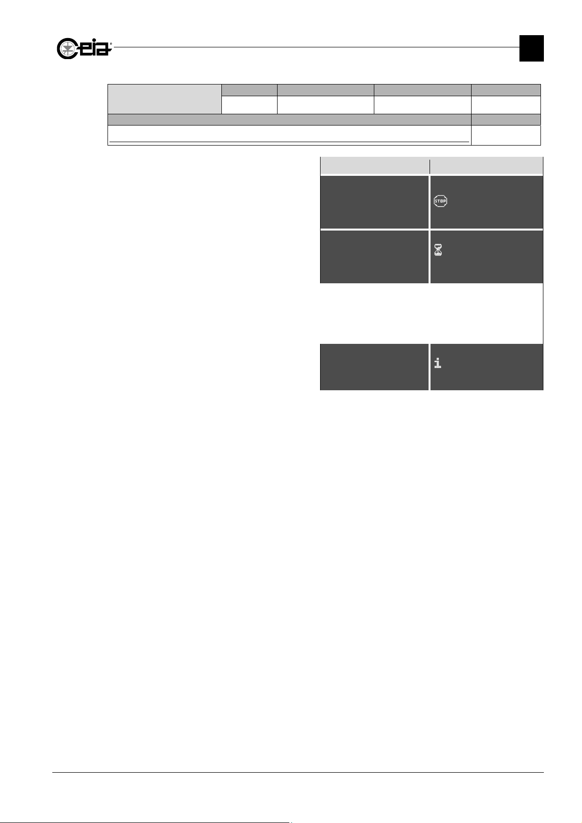
FI002K0021v1100UK – THS/21E and THS/21 Programming Manual
\\\\\\\\\\]
\\\\\\\\\\]
PROGRAMMING PARAMETERS
Remote Possible settings Standard setting Parameter
Save all events
-
- - Global
Description Models
Data saving of all events
All models
If an USB key is not already inserted on the Metal Detector
USB plug, a message will be shown at the operation start.
=====================
Insert USB memory
Press P to exit
---------------------
THS/xx21E THS/xx21
[\\\\\\\\\\\\\\\\\\\]
Insert USB memory
Press P to exit
{|||||||||||||||||||}
3
In presence of several events, a message will ask to wait.
=====================
WAIT
CAN TAKE MINUTES
---------------------
[\\\\\\\\\
{|||||||||||||||||||}
The Metal Detector events are saved as:
:/Ceia/SNxxxxxxxxxxx/Log/xxxxxxxxxxx_YYYYMMDD_HHMM.LOG
where xxxxxxxxxxx is the Metal Detector serial number, YYYYMMDD_HHMM is the datestamp.
At the end of the operation, the message “Done” is shown.
=====================
Done
---------------------
[\\\\\\\\\
{|||||||||||||||||||}
WAIT
CAN TAKE MINUTES
Done
67
Page 68
FI002K0021v1100UK – THS/21E and THS/21 Programming Manual
1st test del
3
PROGRAMMING PARAMETERS
3.18 Q-C setup (Quality Control)
List of parameters available under the Q-C setup menu.
Remote Possible settings Standard setting Parameter
1st test delay
FTD
Description Models
Time delay for the first automatic Test Request
The periodical test request enabled (TE > 0) is requested. The first scheduled Test will be requested
after FTD delay from each Metal Detector start-up.
See also TE parameter.
Remote Possible settings Standard setting Parameter
Test period
TE
Description Models
Time interval between automatic Test Requests
TE parameter allows to enable the Tests Requests scheduling, as explained below:
TE=00:00: the automatic Test Requests are disabled
TE>00:00: the Tests are requested every TE interval (from the First Test, see FTD), through the
display message “Test”, the activation of an external lamp signal (BLUE LAMP Output)
and eventually the TEST Relay activation (according to TRM parameter). At the Test
Request, enter in the programming and perform the test according to set criteria (see TD
and TMD parameters).
In every moment, through the Status Screen, it is possible to see when the next Test request is
scheduled.
Remote Possible settings Standard setting Parameter
Test max delay
TD
Description Models
Maximum allowed time for the Test execution start
Maximum time delay (since the Test Request) within the Test should be started. If this time expires,
the Fault “Test timeout” is activated. See also FT parameter.
It is not possible to set TD>TE.
Remote Possible settings Standard setting Parameter
Test mode
TMD
Description Models
Test execution method
This parameter sets the Metal Detector Test execution mode, as explained below:
SINGLE: it is requested to perform one of the three Tests (FE, NFE or SS Test)
TRIPLE: it is requested to perform all the 3 Tests (Fe, NFe and SS Test), consecutively.
FE/SS, NFE/SS, FE/NFE: it is requested to perform the 2 indicated Tests, consecutively.
The Metal Detector Test is considered Passed if all the requested Tests are passed. The Metal Detector
Test is considered Failed at the first Test Failed occurred.
00:00 – 23:59 00:05
00:00 – 23:59 00:00
00:00 – 23:59 00:00
SINGLE, TRIPLE,
FE/SS, NFE/SS,
SINGLE
FE/NFE
Test period
Test max delay
Test mode
Sample ampl.check
Quick test
Succ.test mandat
ay
Global
All models
Global
All models
Global
All models
Global
All models
68
Page 69
FI002K0021v1100UK – THS/21E and THS/21 Programming Manual
PROGRAMMING PARAMETERS
Remote Possible settings Standard setting Parameter
Sample ampl. check
SAC
Description Models
Sample Amplitude Check
If SAC = “Xv” value, during each test the Metal Detector checks that the Test sample signal level will
not be “v” times higher than the alarm threshold set by the SE value. Otherwise, the corresponding
Test Failed Fault is activated, the message “TEST FAILED, SAMPLE TOO BIG” is shown and the
Test is recorded as NO (not passed). The value of X4 Is equivalent to a 12 dB signal.
Set SAC=OFF to disable this control.
Quick test
Remote Possible settings Standard setting Parameter
QCKT
Description Models
Quick test
If QCKT is set to a value different from OFF, in case of IN_AUX1 Input activation the corresponding
Test request is immediately activated, without the need to enter in Programming. Pass the Test
sample within 1 minute. In case ARM=0, the activation of IN_AUX1 input will activate also AUX relay
for 3 seconds (see also parameter ARM).
Set QCKT=OFF to disable the Quick Test functionality.
See also the Electrical Diagram in Installation Manual.
Succ.test mandat
Remote Possible settings Standard setting Parameter
STM
Description Models
Successful test mandatory
STM = OFF: in case of a failed test, it is possible to reset the system
STM = ON: in case of a failed test, it is mandatory to reset the system, to repeat the test and to
.
pass it
OFF, X2, X3, X4,
X6, X8, X12, X16,
X24, X32
OFF / FE / NFE / SS -
ON / OFF OFF
X4
Global
All models
Global
All models
Global
All models
3
69
Page 70
FI002K0021v1100UK – THS/21E and THS/21 Programming Manual
FE di
3
PROGRAMMING PARAMETERS
3.19 Test samples
List of parameters available under the Test samples menu.
FE diameter
Description Models
Diameter of Ferrous sample sphere used to perform the test
Setting FD > 0, this diameter value will be associated with the corresponding Test and consequently
shown at the moment of the corresponding Test execution.
NFE diameter
Description Models
Diameter of Non-Magnetic metal sample sphere used to perform the test
Setting ND > 0, this diameter value will be associated with the corresponding Test and consequently
shown at the moment of the corresponding Test execution.
SS diameter
Description Models
Diameter of Stainless Steel sample sphere used to perform the test
Setting SD > 0, this diameter value will be associated with the corresponding Test and consequently
shown at the moment of the corresponding Test execution.
ameter
NFE diameter
SS diameter
Remote Possible settings Standard setting Parameter
FD
This value is only recorded in the events buffer (for Quality Control Report using) but it does not affect the
Detection sensitivity. If set to 0, no value will be recorded with the relative test.
Remote Possible settings Standard setting Parameter
ND
This value is only recorded in the events buffer (for Quality Control Report using) but it does not affect the
Detection sensitivity. If set to 0, no value will be recorded with the relative test.
Remote Possible settings Standard setting Parameter
SD
This value is only recorded in the events buffer (for Quality Control Report using) but it does not affect the
Detection sensitivity. If set to 0, no value will be recorded with the relative test.
0.0 – 25.0 mm -
0.0 – 25.0 mm -
0.0 – 25.0 mm -
Related to the
current product
All models
Related to the
current product
All models
Related to the
current product
All models
3.20 Unlock bin
Unlock bin
Description Models
Opening of the electric lock of the bin
Activating this command, the electric lock of the bin is unlocked for a time specified by parameter
UBT.
This command is available only if BWL=ON.
70
Remote Possible settings Standard setting Parameter
-
- -
Global
All models
Page 71
FI002K0021v1100UK – THS/21E and THS/21 Programming Manual
PROGRAMMING PARAMETERS
3.21 Commands accessible only in Remote Programming
3
-
Description Models
Exit from remote programming
Type this command to exit from the Remote Programming.
If RPTO=ON, the Metal Detector exit automatically from the Remote Programming in case of 5
minutes of programming inactivity.
-
Description Models
Software version
Provides the software version loaded on the
Metal Detector.
-
Description Models
Help
Provides the list of all available parameters, their meanings and their current settings
-
Description Models
Current date insertion
DD = Day, MM = Month
YY = last two figures of the year
-
Description Models
Reset total alarm counter
AR command resets the total alarms counter (AC).
-
Description Models
Reset of the current product counters
CR command resets both Alarms and Objects counter related to the current product (CA and CO
respectively).
-
Description Models
Reset total pack transit counter
OR command resets the total objects counter (OC).
Remote Possible settings Standard setting Parameter
PE
Remote Possible settings Standard setting Parameter
PV
Remote Possible settings Standard setting Parameter
HE
Remote Possible settings Standard setting Parameter
DA
Remote Possible settings Standard setting Parameter
AR
Remote Possible settings Standard setting Parameter
CR
Remote Possible settings Standard setting Parameter
OR
- -
- -
#PV <ENTER>
THS/21 V5.330 - ALM V5.260
- -
DD/MM/YY -
#DA 04/03/11 <ENTER>
#
- -
- -
- -
Global
All models
Global
All models
Global
All models
Global
All models
Global
All models
Related to the
current product
All models
Global
All models
71
Page 72
FI002K0021v1100UK – THS/21E and THS/21 Programming Manual
3
PROGRAMMING PARAMETERS
-
Remote Possible settings Standard setting Parameter
PS
Description Models
List of all current product parameters and their value
List of parameters related to the current Product, together with their actual value.
Remote Possible settings Standard setting Parameter
-
PT
Description Models
List of the current parameters settings
List of all parameters, both global and related to the current product, with their current settings.
Other data about the Metal Detector Status and current configuration are included too.
-
Remote Possible settings Standard setting Parameter
EPT
Description Models
Complete list of parameters settings
List of all parameters, both global and related to each product, with their current settings.
Other data about the Metal Detector Status, current configuration and users list are included too.
-
Remote Possible settings Standard setting Parameter
SN
Description Models
Serial number of the Metal Detector
-
Remote Possible settings Standard setting Parameter
RPTO
Description Models
Remote programming timeout
RPTO = ON: The remote programming session will be terminated automatically if no commands
are entered for a period of 5 minutes.
RPTO = OFF: The remote programming session will be terminated only through PE command.
-
Remote Possible settings Standard setting Parameter
RO
Description Models
Read out of the signal level
When the system connected to the detector sends the command “RO(CR)” the metal detector
(MD) will answer with “RO xxx(CR)(CR)#” where “xxx” are ASCII characters from 0 to 100. The
threshold for metal alarm is at 20. The resolution is 1.
(SP) stands for Space and (CR) stands for Carriage Return.
- -
- -
- -
- -
ON / OFF ON
- -
Related to
current product
All models
Related to
current product
All models
Global
All models
Global
All models
Global
All models
Global
All models
72
Page 73
FI002K0021v1100UK – THS/21E and THS/21 Programming Manual
PROGRAMMING PARAMETERS
-
Description Models
Display and Alarm Led status
The MD replies to this command with “DL(SP)” followed by a 81-character string, (CR), (CR) and ‘#’.
The firsts 80 characters of the string are the image of the THS display. The last character is the
Alarm Led Status (‘0’ = Off, ‘1’ = On).
The command is available only if DMD=ALPHA.
(SP) stands for Space and (CR) stands for Carriage Return.
-
Description Models
Display and Alarm Led status (as UNICODE)
The MD replies to this command with “DLU(SP)” followed by a 161-character string, (CR), (CR) and
‘#’. The firsts 160 characters of the string are the image of the THS display in UNICODE. The last
character is the Alarm Led Status (‘0’ = Off, ‘1’ = On).
The command is available only if DMD=ALPHA.
(SP) stands for Space and (CR) stands for Carriage Return.
-
Description Models
UP, DOWN, PROG and ENTER keys status
Remote Possible settings Standard setting Parameter
DL
Remote Possible settings Standard setting Parameter
DLU
Remote Possible settings Standard setting Parameter
KS
- -
- -
- -
Global
All models
Global
All models
Global
3
This command is used to set the , , and keys status of the MD. The command
sequence is:
KS(SP)abcd(CR)
where “abcd” is the key sequence UP (a), DOWN (b), PROG (c), ENTER (d) and it can be
represented by the ASCII character ‘0’ (key pressed) or ‘1’ (key not pressed). For example, when the
key PROG is pressed, abcd = 0010.
Digit KS(SP)0000(CR) to release all the keys.
-
Description Models
Ferrous Quality Test
When the system connected to the THS sends the command “FQ 1(CR)” the Metal Detector starts
the Ferrous Quality Test procedure. Checking FQ (which returns an ASCII character from 0 to 5)
allows the checkweigher to know the status of the test. This is a list of the statuses of the test:
0 Test not running 3 Test passed
1 Test initialisation / signal measurement 4 Test not passed
2 Wait for a product with a ferrous sample 5 Sample too big
The ‘Stainless-steel’ and ‘Non-ferrous’ tests works as the ‘Ferrous’ test.
The samples that have to be used to perform the production test are indicated by the value of the
parameters ‘FD’, ‘SD’ and ‘ND’ of the product under test.
Remote Possible settings Standard setting Parameter
FQ
- -
All models
Global
All models
73
Page 74
FI002K0021v1100UK – THS/21E and THS/21 Programming Manual
3
PROGRAMMING PARAMETERS
-
Description
Self-Check
This command returns a list of all the Metal Detector status flag which are active.
The Metal Detector will reply to this command with “SC xx,xx,…..,xx(CR)(CR)#” where “xx” are ASCII strings with the
following meanings:
00 WORKING PROPERLY - 20 LOGIN RESTRICTED F 40 RESET EMERGENCY F
01 NO COMMUNICATION F 21 EVENT BUFFER FULL F 41 EJEC.CHECK FAULT F
02 EMERGENCY F 22 EJECT.SYSTEM JAM F 42 SYNC.PHOTOC.FAULT F
03 NO EJECT.CONFIRM F 23 EJECT. DISCONNEC. F 43 CHECK PHOTC.FAULT F
04 BIN FULL F 24 Reserved - 44 ENCOD.FRQ.TOO LOW F
05 LOW AIR PRESSURE F 25 Reserved - 45 ENCD.FRQ TOO HIGH F
06 POW. SUPPLY FAULT F 26 Reserved - 46 INVERTER NOT RESP F
07 MOTOR ALARM F 27 Reserved - 47 MOTOR FAULT (AUX) F
08 PROBE FAULT (0) F 28 Reserved - 48 EJECT.OUT OF ORDER F
09 PROBE FAULT (1) F 29 TEST FAILED F 49 ALR RATE TOO HIGH F
10 PROBE FAULT (2) F 30
PASS PRODUCT
11
during Autolearn
12 TEST R 32 BIN ABSENT F 52 LOGIN RESTRIC(2) F
13 TEST TIME OUT F 33 PROBE FAULT (4) F 53 Vin FAULT F
14 Autolearn in progress S 34 PROBE FAULT (5) F 54 Vout FAULT F
15 Reserved - 35 PROBE FAULT (3/1) F 55 PROBE FAULT (0/1) F
16 Reserved - 36 PROBE FAULT (3/2) F 56 PROBE FAULT (0/2) F
17 SPM NOT DETECTED F 37
18 COMPATIBIL.ERROR F 38 EXTERN.EMERGENCY F 58 WARN: IXC timeout W
POWER SUPPLY
19
TOO HIGH
F: Fault – R: Request – S: Status – W: Warning
Some fault messages are not applicable to all models
-
Description Models
Stainless Steel Quality Test
See FQ command.
-
Description Models
Non-Ferrous Quality Test
See FQ command.
Remote Possible settings Standard setting Parameter
SC
R 31 Reserved - 51 LOGIN RESTRIC(1) F
F 39 EMERG.CIRC.FAULT F 59 !! Detect.inhibited!! S
Remote Possible settings Standard setting Parameter
SQ
Remote Possible settings Standard setting Parameter
NQ
- -
FAIL-SAFE TEST
FAILED
SELF BALANCING(x) IN
PROGRESS
- -
- -
Global
F 50 UPDATING CONFIG F
S 57 SCD CARD FAULT (x) F
Global
All models
Global
All models
74
Page 75
FI002K0021v1100UK – THS/21E and THS/21 Programming Manual
PROGRAMMING PARAMETERS
-
Description Models
Exit from programming
When you send this command to the THS Metal Detector, the screen will jump directly to TOP
screen from anywhere in the programming tree. There is only an exception to take into
consideration: it is not possible to leave programming phase when a MD test is in progress, so if you
issue an EX command during a MD test you receive the message "Unable to exit".
Remote Possible settings Standard setting Parameter
EX
- -
Global
All models
3
75
Page 76

FI002K0021v1100UK – THS/21E and THS/21 Programming Manual
3
PROGRAMMING PARAMETERS
3.22 Remote programming
Programming can be carried out through a remote computer fitted with an RS232 interface, a
Bluetooth connection, or an Ethernet/WiFi connection, depending on their availability on the
Metal Detector, using a standard communications program (e.g. Windows HyperTerminal) or the
CEIA MDScope program, available on request.
3.22.1 Communication parameter settings
3.22.1.1 RS232 or RS232 Aux
Select the COM port used (with USB/RS232 adapter, check the COM port assigned).
Set the port as follows:
- Baud rate as set in parameters
BR (for RS232) or
AUBR (for RS232Aux).
Default value: 57600 bit/s
(9600 is also selectable).
- 8 data bits
- NO parity
3.22.1.2 Bluetooth
- Open the Bluetooth software present in your computer.
- Create a new connection. The software will scan the area for available Bluetooth devices.
In the list will appear a device named with the THS model and Serial Number.
For example:
- Selecting this unit, a PIN code will be requested. The device PIN is stored on the parameter
, under Administrator menu (the default value is 00000000).
BPIN
- The Bluetooth connection software will connect now to the unit, showing a message that will
indicate which virtual COM port has been created for the device. For example:
- Set the assigned COM port and Baud Rate (57600bps) in the communication parameter
settings.
3.22.1.3 Ethernet / WiFi connections (with IXC card)
- Set all connection parameters as indicated in paragraph 3.23.1.
- Set TCP port to a value of 2101.
CDSN 99999999 THS/XX
- 1 stop bit
- no communication protocol
- CR -> CR+LF
- Local echo = OFF
- Terminal: VT 100 (ANSI)
COM42
.
76
Page 77
FI002K0021v1100UK – THS/21E and THS/21 Programming Manual
3.22.2 Entering remote programming
3.22.2.1 Connecting to a Metal Detector
Via RS232 or Bluetooth
- Run the serial communication program (MD Scope) or another serial communication
software
- Perform the access by typing the password
(or login and password) as stated by
parameter RM (for RS232 and Bluetooth) or
AURM (for RS232Aux) and confirming with
ENTER
Default password: 000006
When typing the password, nothing is displayed on the screen.
The # prompt will be shown only after a correct password authentication
Via Ethernet or WiFi (with IXC board)
Perform the access by typing login and password, and confirming with ENTER.
During the typing, an asterisk (*) will be shown in place of each character.
Default administrator login: user: ADMINI; password: 000000.
3.22.2.2 Displaying a parameter setting
Type the code of the parameter and press ENTER:
the parameter setting will appear next to it.
For further details on the MD Scope program, please refer to the manual supplied with the
software.
3.22.2.3 Changing a parameter setting
Type the code of the parameter followed by a
space, the new value and ENTER.
3.22.2.4 Executing a function
Key in the parameter code and press ENTER.
PROGRAMMING PARAMETERS
(password) <ENTER>
#
#SE<ENTER>
#SE 30
#SE 35<ENTER>
#
#PL<ENTER>
#
3
77
Page 78
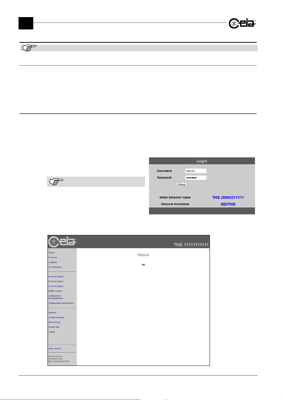
FI002K0021v1100UK – THS/21E and THS/21 Programming Manual
3
PROGRAMMING PARAMETERS
3.23 Access via Web Server
This paragraph applies only if a IXC card is fitted.
3.23.1 Network configuration
To configure the THS system on a network, use the following procedure:
- Enter the programming phase as Administrator;
- Enter the
- Correctly set all parameters to connect the THS system with your network;
- Set
3.23.2 Functions available
When the THS system is connected through Ethernet to the network, it is possible to perform some
operations by means of a simple browser.
The operator needs only to know the IP address (or the Network Hostname) of the device.
- Open your browser and enter the THS IP in the URL field (to know the default IP address,
see IPA parameter). Be sure that no Proxy is active.
- The THS will ask for a login name and
a password. Access with your account.
Configuration-adv
Web server
to ON.
menu and the
Network config.
submenu;
The operation is not case sensitive.
- The screen will be divided in two areas, the menu column on the left and the content area on
the right.
78
Page 79
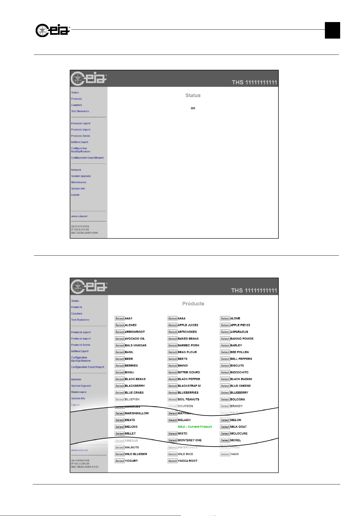
3.23.2.1 Status
This page replicates every message the THS shows on the display. The page is updated each 5 s.
FI002K0021v1100UK – THS/21E and THS/21 Programming Manual
PROGRAMMING PARAMETERS
3
3.23.2.2 Products
This page shows the list of product saved into the THS memory, showing the selected product in
green. To select a new one, press on the corresponding Select button.
79
Page 80
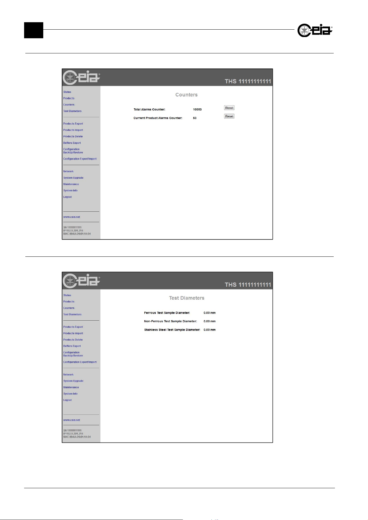
FI002K0021v1100UK – THS/21E and THS/21 Programming Manual
3
PROGRAMMING PARAMETERS
3.23.2.3 Products Counters
This page shows, in real time, the alarm counters status.
3.23.2.4 Test Diameters
This page shows the diameter values of all the test samples.
80
Page 81
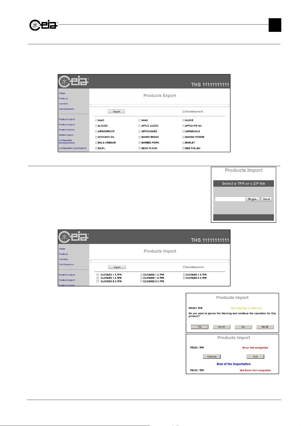
3.23.2.5 Products Export
From this page it is possible to select all or some of the products stored in the THS memory, to
export them.
Each selected product will be saved in a ProductName.TPR file and all of them will be saved into
a Exported_Products.zip file.
FI002K0021v1100UK – THS/21E and THS/21 Programming Manual
PROGRAMMING PARAMETERS
3
3.23.2.6 Products Import
From this page will be possible to import back all or some of the
products exported, selecting a .tpr or a .zip file and selecting from
the list.
It is possible to import products created on other Metal
Detectors (of the same model), but with different probe
dimensions.
In this case, for this products, can be necessary to
perform a new Autolearn procedure.
It is not possible to import products created on
different Metal Detector models.
The product DEFAULT and the current product cannot
be overwritten.
81
Page 82
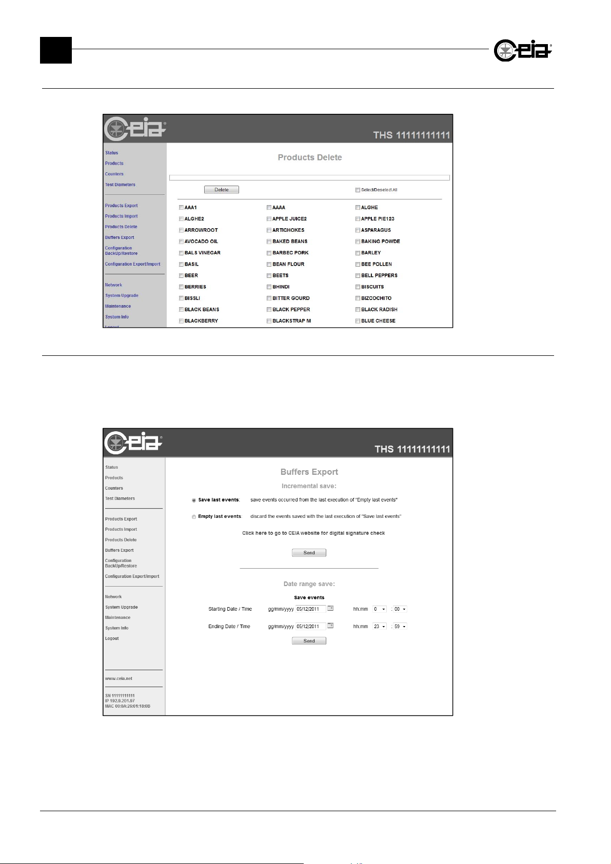
FI002K0021v1100UK – THS/21E and THS/21 Programming Manual
3
PROGRAMMING PARAMETERS
3.23.2.7 Products Delete
If needed, from this page it is possible to delete products.
3.23.2.8 Buffers Export
Inside this page it is possible to export events data that occurred in from the Starting Date / Time to
the Ending Date / Time requested. Once the two dates are set and the Send button has been
pressed, a link to download the file appears.
The log file is saved as serialnumber_Startingdate-Endingdate.zip that contains the file
serialnumber_Startingdate-Endingdate.LOG requested.
82
Page 83
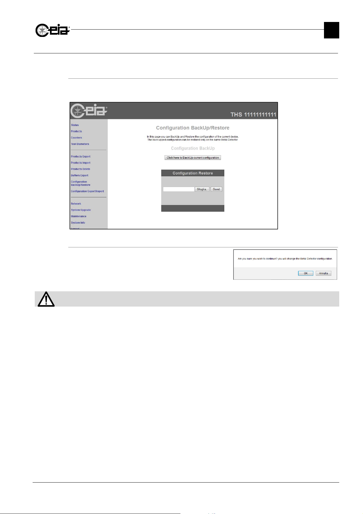
3.23.2.9 Configuration Backup/Restore
From this page it is possible to backup or to restore the configuration for the connected system.
Configuration Backup
To perform a configuration backup, simply press on Click here to Backup current configuration.
The file will be saved as SerialNumber.TCB.
FI002K0021v1100UK – THS/21E and THS/21 Programming Manual
PROGRAMMING PARAMETERS
3
Configuration Restore
To perform a configuration restore, choose a TCB file
from your computer and upload it to the THS system.
A confirmation is needed.
The TCB configuration files are restorable ONLY on the same machine from where they were saved.
83
Page 84
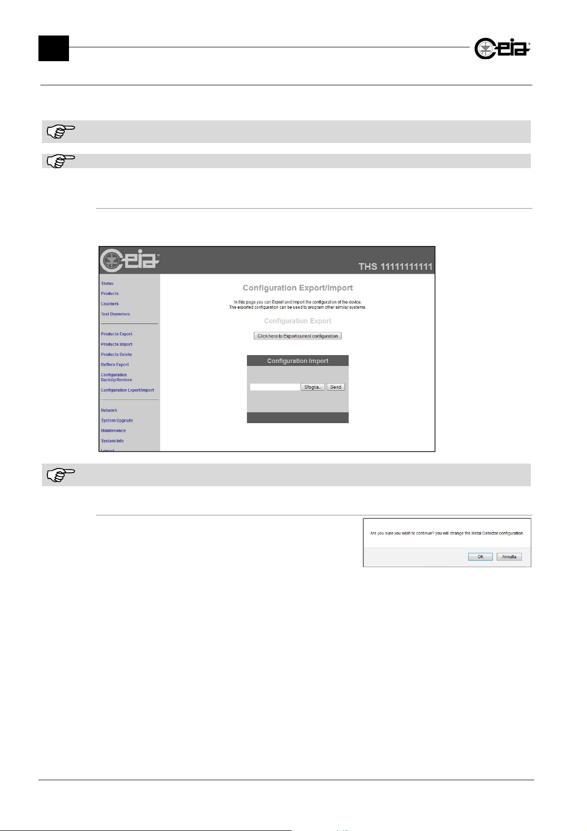
FI002K0021v1100UK – THS/21E and THS/21 Programming Manual
3
PROGRAMMING PARAMETERS
3.23.2.10 Configuration Export/Import
From this page it is possible to export the configuration to or to import it from other Metal Detectors
of the same model, installed on identical systems.
It is possible to import configuration from Metal Detectors of the same model, installed on identical systems, but with
different probe dimensions. The correct functioning of the systems is however to be verified.
It is not possible to import configurations of different Metal Detector models.
Configuration Export
To perform a configuration export, simply press on Click here to Export current configuration.
The file will be saved as SerialNumber.TCE.
The exported configuration does not include all parameters relative exclusively to each system (for example IP address,
motor configuration parameters, barcode reader activation code etc..).
Configuration Import
To perform a configuration import, choose a TCE file from
your computer and upload it to the THS system.
A confirmation is needed.
84
Page 85
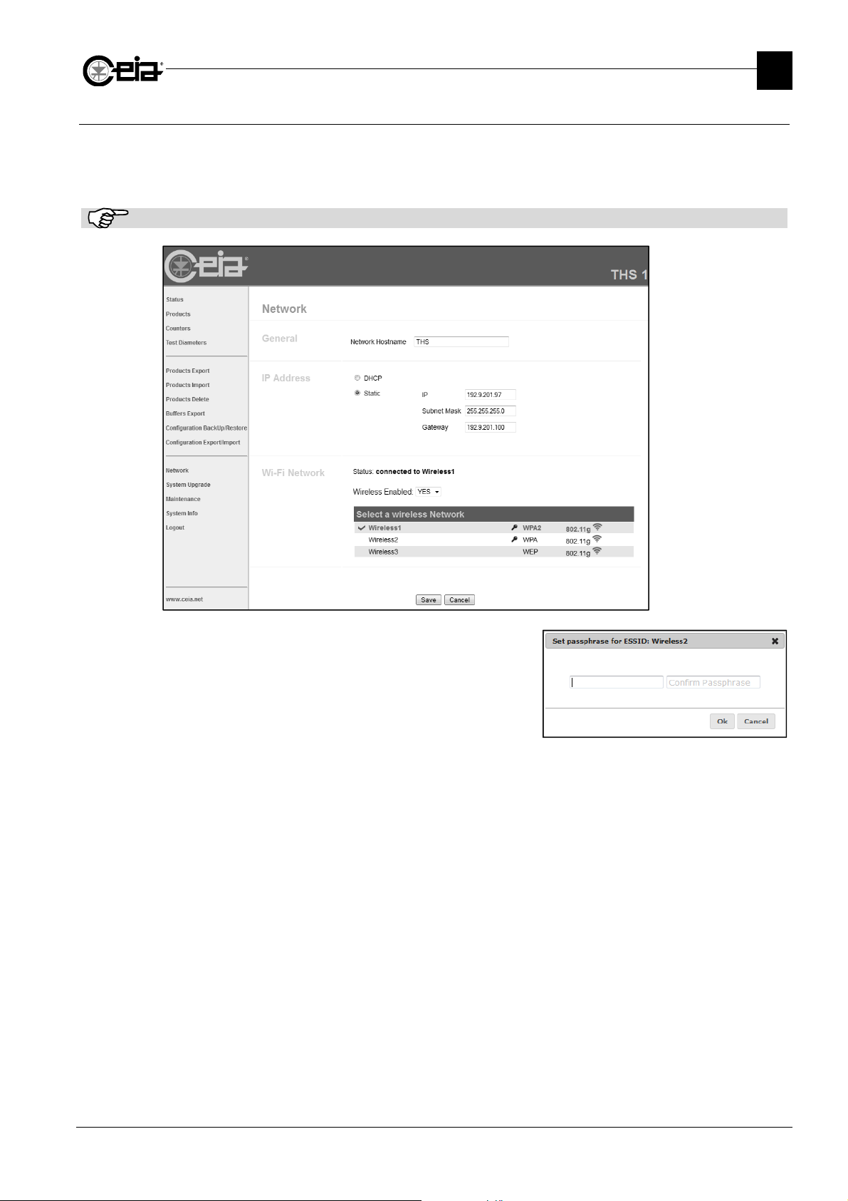
3.23.2.11 Network
This function allows to set all network data of the THS system.
When using DHCP protocol, the IP address will be assigned automatically by the network system.
Otherwise, using a static addressing, the network data must be entered manually.
The changes take place by pressing the Save button.
Network data as IP, Subnet Mask, Gateway, are related both for the Ethernet and the WiFi connections.
FI002K0021v1100UK – THS/21E and THS/21 Programming Manual
PROGRAMMING PARAMETERS
3
In case the network connection needs the insertion of a
password, this will be requested in a proper pop-up
window.
85
Page 86
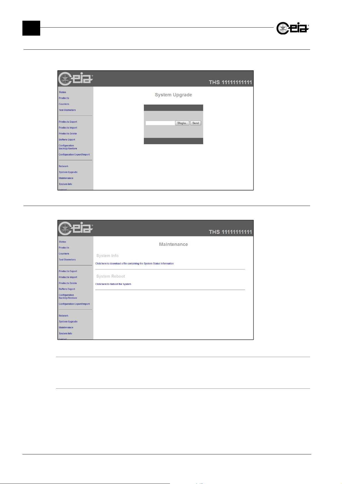
FI002K0021v1100UK – THS/21E and THS/21 Programming Manual
3
PROGRAMMING PARAMETERS
3.23.2.12 System upgrade (Web Server)
This function allows upgrading the Web Server installed on the IXC board, using a .rar file provided
by CEIA service department.
3.23.2.13 Maintenance
This function allows performing some maintenance operations.
System Info
This function allows saving a file containing the IXC board Information.
This file must be sent to CEIA service department.
System Reboot
This function allows performing a Reboot of the IXC System.
86
Page 87
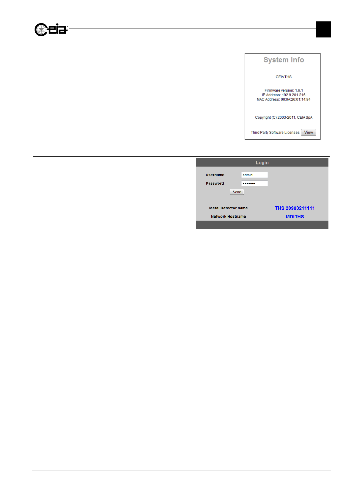
3.23.2.14 System Info
This function displays some relevant information about the Web
Server.
3.23.2.15 Logout
This function allows logging out the session.
Simply click on the menu “Logout”: the dialog
box for the login of a new user appears.
FI002K0021v1100UK – THS/21E and THS/21 Programming Manual
PROGRAMMING PARAMETERS
3
87
Page 88

FI002K0021v1100UK – THS/21E and THS/21 Programming Manual
3
PROGRAMMING PARAMETERS
Page left intentionally blank
88
Page 89

FI002K0021v1100UK – THS/21E and THS/21 Programming Manual
4 APPENDIX
4.1 Parameters list – Alphabetical order
PROGRAMMING PARAMETERS
3
AC .............................................. 32
ACCT ......................................... 51
ADMS ......................................... 24
ADS ............................................ 42
AM .............................................. 47
AP .............................................. 59
APDL .......................................... 59
AR .............................................. 71
ARM ........................................... 49
ARP ............................................ 61
ART ............................................ 62
ASE ............................................ 25
AT .............................................. 35
ATD ............................................ 45
ATTM ......................................... 45
ATTP .......................................... 44
AUBR ......................................... 52
AURM ........................................ 16
BA .............................................. 27
BARC ......................................... 19
BD .............................................. 54
BE .............................................. 41
BL ............................................... 41
BLEN .......................................... 34
BM .............................................. 42
BPIN ........................................... 16
BR .............................................. 52
BS .............................................. 42
BT .............................................. 52
BTS ............................................ 53
BWL ........................................... 58
CA .............................................. 32
CBT ............................................ 53
CE .............................................. 59
CH .............................................. 34
CO .............................................. 32
CPMA ......................................... 57
CR .............................................. 71
CT .............................................. 59
DA ........................................ 35; 71
DC .............................................. 45
DDD ........................................... 45
DECT ......................................... 51
DI ............................................... 43
DL .............................................. 73
DLU ............................................ 73
DM ............................................. 26
DMD ........................................... 45
DNS ........................................... 40
DT .............................................. 52
EA .............................................. 60
ECK ............................................ 59
ECKA ......................................... 60
ECPD ......................................... 43
ED .............................................. 30
EDA ............................................ 26
EE .............................................. 31
EF .............................................. 62
EIS ............................................. 48
EJ ............................................... 36
EM .............................................. 28
EMEX ......................................... 62
EP .............................................. 19
EPC ........................................... 60
EPCD ......................................... 60
EPT ............................................ 72
ERF ........................................... 43
ERL ............................................ 48
ERT ........................................... 43
ES .............................................. 31
ESO ........................................... 34
ET .............................................. 30
EV .............................................. 65
EX .............................................. 75
FB .............................................. 61
FC .............................................. 48
FD .............................................. 70
FF .............................................. 61
FLR ............................................ 61
FO .............................................. 41
FQ .............................................. 73
FT .............................................. 61
FTD ............................................ 68
GW ............................................ 40
HE .............................................. 71
HN ............................................. 40
HPR ........................................... 40
IA ............................................... 46
IAP ............................................. 47
IBF ............................................. 52
IE ............................................... 46
IFLY ........................................... 51
IL ................................................ 46
IN ............................................... 41
IP ............................................... 46
IPA ............................................. 40
IPF ............................................. 52
IRST .......................................... 52
IW .............................................. 46
IXC ............................................. 37
KAR ........................................... 35
KE .............................................. 43
KFR ........................................... 35
KS .............................................. 73
KT .............................................. 43
LA .............................................. 58
LAD ............................................ 58
LC .............................................. 54
LE .............................................. 24
LF .............................................. 58
LFD ............................................ 58
LG .............................................. 34
LO .............................................. 45
MAC ........................................... 40
MASE......................................... 25
MB ............................................. 24
MI ............................................... 51
MM ............................................. 36
MOPT ........................................ 25
ND ............................................. 70
NE .............................................. 55
NM ............................................. 40
NMC .......................................... 50
NMCP ........................................ 50
NME ........................................... 50
NMF ........................................... 51
NMP ........................................... 50
NMS ........................................... 51
NMV ........................................... 50
NQ .............................................. 74
NW ............................................. 19
OC .............................................. 32
OR .............................................. 71
PA............................................... 57
PAT ............................................ 57
PB............................................... 65
PC .............................................. 48
PD .............................................. 42
PDIS ........................................... 60
PE............................................... 71
PFR ............................................ 62
PH .............................................. 42
PI .......................................... 17; 18
PL ............................................... 64
PLEN .......................................... 30
PN .............................................. 18
PS............................................... 72
PT ............................................... 72
PV............................................... 71
QCKT ......................................... 69
QR .............................................. 47
RD .............................................. 47
RE .............................................. 49
RM .............................................. 16
RO .............................................. 72
RPTO ......................................... 72
RS .............................................. 17
SA............................................... 25
SAC ............................................ 69
SC .............................................. 74
SD .............................................. 70
SE............................................... 26
SF ............................................... 36
SN .............................................. 72
SO .............................................. 34
SPMA ......................................... 57
SQ .............................................. 74
ST ............................................... 49
STM ............................................ 69
TA ............................................... 44
TA1 ............................................. 44
TA2 ............................................. 44
TD............................................... 68
TE ............................................... 68
TL ............................................... 44
TM .............................................. 35
TMD ............................................ 68
TN............................................... 24
TP ............................................... 27
TRM ............................................ 49
TX ............................................... 34
UBT ............................................ 58
UD .............................................. 36
VI ................................................ 26
WE.............................................. 53
WEBS ......................................... 41
WS.............................................. 53
WT .............................................. 33
89
Page 90

FI002K0021v1100UK – THS/21E and THS/21 Programming Manual
4
APPENDIX
4.2 Parameters list – Menu order
Administrator .................................. .................. 15
Create user..................................... .................... 15
Modify user ..................................... .................... 15
Erase user ...................................... .................... 16
Set Bluetooth PIN ................... BPIN .................... 16
Remote passwords ......................... .................... 16
RS232password ................ RM .................... 16
auxRS232passw .......... AURM .................... 16
Reset ........................................... RS .................. 17
Product selection ............................ .................. 17
Product ........................................ PI .................... 17
Products .......................................... .................. 18
Product ........................................ PI .................... 18
Rename product ........................ PN .................... 18
New product ............................. NW .................... 19
Erase product ............................ EP .................... 19
Prod. barcode ....................... BARC .................... 19
Save prod.to USB ........................... .................... 20
Select product(s) .................... .................... 20
Save all products ................... .................... 21
Load prd from USB ......................... .................... 22
Select product(s) .................... .................... 22
Load all .................................. .................... 23
Autolearn ......................................... .................. 24
Autolearn .................................... LE .................... 24
Aut.det.,mode sel ................. ADMS .................... 24
Multi-band.................................. MB .................... 24
Min.trans.numb .......................... TN .................... 24
Autolearn-advanc ........................... .................. 25
Metal optimiz. ....................... MOPT .................... 25
Autolearn sens. ....................... ASE .................... 25
Sens. margin ............................. SA .................... 25
Max learn sens ..................... MASE .................... 25
Vibr.immunity ............................... VI .................... 26
Ej.during autlr .......................... EDA .................... 26
Detection .......................................... .................. 26
Sensitivity .................................. SE .................... 26
Detection mode ......................... DM .................... 26
TX program ................................ TP .................... 27
Band .......................................... BA .................... 27
Ejection ............................................ .................. 28
Ejection mode ........................... EM ............... 28/29
Ej. distance ................................ ED .................... 30
Ejection time .............................. ET .................... 30
Pack length ........................... PLEN .................... 30
Ej.st.sync.area ........................... ES .................... 31
Ej.en.sync.area .......................... EE .................... 31
Counters .......................................... .................. 32
Prd alarms ................................. CA .................... 32
Prd packs .................................. CO .................... 32
Tot.alarms .................................. AC .................... 32
Tot. packs ................................. OC .................... 32
Work time .................................. WT .................... 33
Configuration .................................. .................. 33
Compatibility chk ............................. .................... 33
Gener.comp.check ................. .................... 33
Elec.comp.check .................... .................... 33
Belt contam.check .................. .................... 33
Belt length .................... BLEN .................... 34
Buzzer ....................................... SO .................... 34
Ext. buzzer .............................. ESO .................... 34
Language ................................... LG .................... 34
Transmission ............................. TX .................... 34
TX Channel ............................... CH .................... 34
Keyb alarm reset ..................... KAR .................... 35
Keyb fault reset ....................... KFR .................... 35
Time .......................................... TM .................... 35
Date ........................................... DA .................... 35
Alarm time .................................. AT .................... 35
Ejection ...................................... EJ .................... 36
UP/DOWN enable ..................... UD .................... 36
Manual motion .......................... MM .................... 36
Stop on fault ............................... SF .................... 36
>>
90
Page 91

Configuration-adv ........................... .................. 37
IXC presence ............................ IXC .................... 37
Backup conf.to USB ........................ .................... 38
Restor.cfg.from USB ....................... .................... 38
Export conf.to USB ......................... .................... 39
Import cfg.from USB ....................... .................... 39
Network config. ............................... .................... 40
HN ..................................... HN .................... 40
Host protocol .................. HPR .................... 40
IP ...................................... IPA .................... 40
NM .................................... NM .................... 40
GW ................................... GW .................... 40
DNS ................................ DNS .................... 40
MAC ............................... MAC .................... 40
Web server .................. WEBS .................... 41
Product tracking ......................... FO .................... 41
Inhib. Time .................................. IN .................... 41
Barcode enable .......................... BE .................... 41
Minimum speed ......................... BL .................... 41
Speed ........................................ BS .................... 42
Maximum speed ....................... BM .................... 42
Phcell position............................ PH .................... 42
Phcell-MD dist............................ PD .................... 42
Check phot.dist ..................... ECPD .................... 42
EjON resp.time ........................ ERT .................... 43
EjOFFresp.time ........................ ERF .................... 43
K transmis. ................................. KT .................... 43
K encoder .................................. KE .................... 43
Diameter ..................................... DI .................... 43
TA .............................................. TA .................... 44
TA1 .......................................... TA1 .................... 44
TA2 .......................................... TA2 .................... 44
TA autolearn ............................... TL .................... 44
Autotest phase ....................... ATTP .................... 44
Autotest module .................... ATTM .................... 45
Autotest diagnos ...................... ATD .................... 45
Display mode .......................... DMD .................... 45
Display contrast ......................... DC .................... 45
Dimming delay ........................ DDD .................... 45
Input logic .................................. LO .................... 45
BIN FULL input ............................ IL .................... 46
BIN ABSENT input ...................... IA .................... 46
EJECT.CONF.input .................... IE .................... 46
PHOTOCELL input ..................... IP .................... 46
FOLLW.CONV.input .................. IW .................... 46
LOW PRESSURE inp ............... IAP .................... 46
Analysys mode ......................... AM .................... 47
Ejec.queue reset ....................... QR .................... 47
Reverse detect........................... RD .................... 47
Eject.act.if stop ......................... EIS .................... 47
EJECT RELAY logic ................ ERL .................... 48
PREC CONV enable .................. PC .................... 48
FOLLW.CONV.enab .................. FC .................... 48
Autom. Restart ........................... RE .................... 48
Mode test relay ....................... TRM .................... 49
Aux relay mode ....................... ARM .................... 49
Stop time ................................... ST .................... 49
FI002K0021v1100UK – THS/21E and THS/21 Programming Manual
PROGRAMMING PARAMETERS
Motor config ................................... .................... 49
Nom.MotorVolt. .............. NMV .................... 49
Nom.MotorCurr. ............. NMC .................... 50
Nom.MotorPower ........... NMP .................... 50
Nom.MotorCosPhi ....... NMCP .................... 50
Nom.MotorEffic .............. NME .................... 50
Nom.MotorFreq .............. NMF .................... 50
Nom.Motor.Speed .......... NMS .................... 50
Max inv. freq. ..................... MI .................... 51
Acceler. Time ............... ACCT .................... 51
Deceler. Time .............. DECT .................... 51
Flying start ...................... IFLY .................... 51
Inv.PulseFreq. ................... IPF .................... 51
Inv.BaseFreq. ................... IBF .................... 51
ResetInv.ToDefault ........ IRST .................... 52
RS232 BaudRate ...................... BR .................... 52
auxRS232B.rate ................... AUBR .................... 52
DTR protocol ............................. DT .................... 52
Bounce time ............................... BT .................... 52
Bounce t. slow ......................... BTS .................... 52
Centre belt time ....................... CBT .................... 53
Barcode reader ............................... .................. 53
Window start ............................ WS .................... 53
Window end ............................. WE .................... 53
Learn code ................................. LC .................... 53
Barc-MD dist. ............................ BD .................... 54
No code eject ............................ NE .................... 54
I/O Status ......................................... .................. 55
Outputs ........................................... .................... 55
Inputs ............................................. .................... 55
Measures ....................................... .................... 55
Variables ........................................ .................... 56
3
>>
91
Page 92

FI002K0021v1100UK – THS/21E and THS/21 Programming Manual
4
APPENDIX
Diagnosis managem. ...................... .................. 56
Photocell fault ............................ PA .................... 56
Sync.max.activ ..................... SPMA .................... 56
Chck.max.activ ..................... CPMA .................... 56
Phot.fau.thres .......................... PAT .................... 57
Bin full ........................................ LF .................... 57
Bin full delay ............................ LFD .................... 57
Bin absent .................................. LA .................... 57
Bin absent delay ...................... LAD .................... 57
Bin with lock ........................... BWL .................... 58
Unlock bin time ........................ UBT .................... 58
Air pressure low ......................... AP .................... 58
Low press. delay ................... APDL .................... 58
Eject confirmat. .......................... CE .................... 58
Confirm time .............................. CT .................... 59
Eject.check .............................. ECK .................... 59
Ej.check accur. ..................... ECKA .................... 59
Pho.diag.if stop ....................... PDIS .................... 59
Ejector pos. chk ....................... EPC .................... 59
Ej.pos.chk delay ................... EPCD .................... 60
Encoder check ........................... EA .................... 60
Test time out ............................... FT .................... 60
Test failed ................................... FF .................... 60
Event buf. full .............................. FB .................... 61
Login restrict. ........................... FLR .................... 61
Al.rate period ........................... ARP .................... 61
Al.rate threshold ...................... ART .................... 61
Ej. max extent ....................... EMEX .................... 61
Ejec.on fault ................................ EF .................... 62
Probe fault reset ...................... PFR .................... 62
MD Test ............................................ .................. 63
FE test ............................................ .................... 63
NFE test .......................................... .................... 63
SS test ............................................ .................... 63
Fail-safe test .................................... .................. 63
Fail-safe test ................................... .................... 63
Print .................................................. .................. 64
Print events ................................ PL .................... 64
Erase printed ev. ........................ EV .................... 65
Print all events ........................... PB .................... 65
Save last events.............................. .................... 65
Empty last events ............................ .................... 65
Save events .................................... .................... 66
Save from-to ........................... .................... 66
Save all products .................... .................... 67
Q-C setup......................................... .................. 68
1st test delay ............................ FTD .................... 68
Test period ................................. TE .................... 68
Test max delay........................... TD .................... 68
Test mode ............................... TMD .................... 68
Sample ampl. Check ............... SAC .................... 69
Quick test .............................. QCKT .................... 69
Succ.test mandat .................... STM .................... 69
Test samples ................................... .................. 70
FE diameter ............................... FD .................... 70
NFE diameter ............................ ND .................... 70
SS diameter ............................... SD .................... 70
Unlock bin ....................................... .................. 70
92
 Loading...