

Ceia HI-PE multi-zone Series, HIPE/PTZ, HIPE /PTZ-WP Installation, Use And Maintenance Manual
Page 1
HI-PE multi-zone --- Rev. FI 050 GB 60K10 v2_1
1
METAL DETECTOR
HI-PE multi-zone
Installation Use and Maintenance
ATTENTION!
This manual contains the necessary instructions for the CEIA equipment described in the test report attached to the end of the
manual itself (Factory Acceptance Test Report). These instructions are not, generally, applicable to equipment different from
that described in the test report.
Rev.:
FI 050 GB 60K10 v2_1
Program Version:
8.11
Date:
2005-04-18
Page 2
2
HI-PE multi-zone --- Rev. FI 050 GB 60K10 v2_1
Installation, use and safety information
READ THESE INSTRUCTIONS BEFORE WORKING WITH THE DEVICE
CEIA can not be held responsible for direct and/or indirect damage to persons and/or property arising
from failure to observe these instructions.
• Read this manual carefully before installing, operating or
carrying out maintenance on the device. Keep this booklet in
a safe place for future reference.
• Follow the instructions contained in this manual for all
operations relating to installation, use and maintenance of the
device. CEIA cannot be held responsible for any damage
resulting from procedures which are not expressly indicated in
this manual.
• The final user is responsible for selecting the appropriate
security level/sensitivity for their application. After this
selection has been made, and programming has been
adjusted accordingly, it is also the final user's
responsibility to verify calibration using the test object(s)
appropriate to the level of security selected. Additionally,
this test should be carried out periodically to insure no
changes have occurred in the equipment.
• Whenever there is any suggestion that the level of protection
has been reduced, the device should be taken out of service
and secured against any possibility of unintentional use, and
authorised service technicians should be called.
The level of protection is considered to have been reduced
when:
- the device shows visible signs of deterioration;
- the device does not operate correctly;
- the device has been stored for a long period in sub-optimal
conditions;
- the device has suffered severe stress during transport;
- the inside of the device has come into contact with liquids.
• Choose the installation site carefully. Avoid placing the device
in locations where it may be directly exposed to sunlight, in
unventilated areas or in places that are close to sources of
heat. In addition, avoid places that are subject to vibrations,
dust, humidity, rain and excessively high or low
temperatures.
• Installation must be carried out by qualified personnel. Given
the dimensions of the device, it is requested that the
installation site be kept clear while work is carried out to
facilitate setting it up and to avoid any harm to third parties.
• Position the device as far away as possible from sources of
electromagnetic interference such as transformers or motors.
• When installation is completed, the detector must be
anchored to the ground in a stable manner and not subject to
vibrations (use expansion screws inserted through the
anchoring holes in the base of the panels). All connecting
cables between the gateway and the power supply or other
external devices must be properly fixed and protected so as to
achieve the best performance from the detector and avoid
accidental injury to people who might trip over them.
• Handle the device with care and without excessive force
during installation, use and maintenance
• Before powering up the device, check that the mains power
supply voltage corresponds to the voltage shown on the
device's electrical specifications plaque. The use of a
different mains voltage may damage the equipment!
The device should be connected to the mains voltage only
after all the connections required for full installation have been
carried out.
• The device must be connected to a power supply circuit fitted
with a switch or other device which allows the power to be cut
off.
• If the device is to be powered via an external autotransformer
to regulate the voltage, ensure that the common terminal of
the autotransformer is connected to the neutral of the powersupply circuit.
• The power-supply plug must only be inserted into a socket
fitted with an earth/ground connection.
Any break in the safety conductor, either inside or outside the
device, or disconnection of the earth/ground safety terminal,
will render the device dangerous. Intentional cutting or
disconnection is strictly forbidden.
• Always remove the plug by hand when disconnecting the
power supply cable, never by pulling on the cable.
• The standard power-supply adapter is not waterproof: place it
in a ventilated position where it is protected from water (rain,
condensation, liquid detergents)! There is a risk of electric
shocks for people and damage to the equipment!
• This device contains electrical and electronic components,
and may therefore be susceptible to fire. Do not install in
explosive atmosphere or in contact with inflammable material.
Do not use water or foam in the case of fire when the device
is powered up.
• To prevent damage by lightning, disconnect the power supply
cable during thunderstorms.
• Do not use in an explosive atmosphere. Avoid contact with
inflammable or explosive material.
• Carry out the periodic maintenance regularly (see section on
Maintenance). Do not wash the device with water, liquid
detergents or chemical substances. Use a slightly moist, nonabrasive cloth for cleaning.
• The device must be disconnected from all power sources
before undergoing any maintenance or cleaning, and before
being moved.
• Read the chapter on “Maintenance” carefully before calling
the service centre.
Whatever the problem, only specialised service personnel
authorised to work with CEIA equipment should be called.
• Any damaged parts of the device should be replaced by
original components only.
Any maintenance or repair involving the device being opened
•
while powered should be avoided as far as possible: if this
becomes inevitable, the operation must be carried out only by
qualified personnel who are fully aware of the risks involved.
• Important advice regarding any batteries incorporated in
the device. When replacing: use CEIA spare parts or
batteries with equivalent electrical/mechanical characteristics.
Do not dispose of used batteries in general rubbish bins; use
public battery collection facilities as per local regulations, or
return them to a CEIA office. If the equipment is to be
disposed of, remove the batteries and dispose of them
separately. CEIA will not hold itself responsible for the
improper use of the batteries incorporated into its equipment:
consult the battery manufacturer for more detailed
information.
• Human exposure to electromagnetic fields. The equipment is
pre-set in the factory according to the regulations applicable
in the destination country. Any modification to this pre-setting
is the responsibility of the installer. For further information
contact the competent bodies. CEIA’s technical/sales
department can provide further clarification.
Page 3
HI-PE multi-zone --- Rev. FI 050 GB 60K10 v2_1
3
Symbols
The device is marked with this symbol whenever the operator or the maintenance personnel,
in order to avoid possible damage, have to refer to the present manual. The same symbol
appears in the booklet at points where warnings or particularly important instructions are given instructions that are vital to a safe and correct use of the device.
The device is marked with this symbol in those areas where a dangerous amount of voltage is
present.
Only specialised maintenance personnel should make adjustments in these areas.
This sign in the manual indicates tips for optimising the device’s performance.
W arranty conditions
The warranty on all CEIA products, extended to the period agreed with the Sales Department, is applicable to goods
supplied from our factory, and for every constituent part thereof, with the exception of the batteries and the card reader.
Any form of tampering with the device, and in particular opening its container, is strictly forbidden and will invalidate the
warranty.
Customer Satisfaction Report
Your suggestions and comments on the products and services offered by CEIA and its distribution network
are extremely important for improving our procedures. We would ask you to send them to us by compiling and
returning the form available:
http://www.ceia.net/security/satisfaction.asp.
Thank you for your kind interest and co-operation.
CEIA reserves the right to make changes, at any moment and without notice, to the models (including programming), their
accessories and optionals, to the prices and conditions of sale.
Page 4

4
HI-PE multi-zone --- Rev. FI 050 GB 60K10 v2_1
CONTENTS
INSTALLATION, USE AND SAFETY INFORMATION 2
SYMBOLS 3
WARRANTY CONDITIONS 3
CONTENTS 4
I - DESCRIPTION 5
OPERATING PRINCIPLE 5
Models 6
CONSTRUCTION OF THE METAL DETECTOR 6
Electronics Unit 6
Archway 7
Standard Model 7
Mains adapter 7
OPTIONS 8
Transit counter 8
Emergency batteries 8
II - INSTALLATION 9
ASSEMBLY 9
Unpacking the Metal Detector 9
Mechanical assembly 9
Assembly of the probe 9
Fixing the electronics unit 10
Positioning 11
Fixing the antenna to the ground 11
Electrical assembly 12
Connecting the electronics unit to the archway
(antenna). 12
Power supply connection 12
Outdoor model for outdoor applications:
assembly 13
Examples of Installations 14
Application in an airport environment 14
Transit flow-rate and secondary metal
detector for inspection in case of alarm 16
Installation of coupled metal detectors synchronisation 17
III - SWITCHING ON AND DISPLAY MESSAGES 18
SWITCHING ON THE METAL DETECTOR 18
DISPLAY MESSAGES 18
Alarm indications 18
Other messages 19
Messages activated via the keypad 19
VISUAL ALARM ZONE INDICATION 20
STAND-BY 21
IV - PROGRAMMING 22
LOCAL PROGRAMMING 22
COMMAND EXECUTION - LOCAL PROGRAMMING 22
Time out 23
DESCRIPTION OF THE COMMANDS 23
Reception Parameters 23
Transmission parameters 24
Alarm signal parameters 24
Management of the Metal Detector 24
ANALYSIS PROGRAMS AVAILABLE WITH
THE COMMAND "IS" 27
INSTALLATION CHECKS 28
ADVANCED PROGRAMMING - REMOTE PROGRAMMING 30
Serial communication 30
Communication system configuration 31
Free access to programming phase (without
password) 31
Execution of commands in remote programming 31
SIMULTANEOUS ACCESS REQUEST BY REMOTE AND
LOCAL PROGRAMMING
ADVANCED PROGRAMMING: USE OF THE
PASSWORD
V - TECHNICAL CHARACTERISTICS 35
VI - MAINTENANCE 36
SUGGESTED MAINTENANCE SCHEDULE 36
DIAGNOSIS 37
TROUBLESHOOTING 38
COMPATIBILITY ASPECTS 39
PROCEDURES 40
VII - APPENDICES 42
DECLARATION OF CE CONFORMITY 42
ELECTRICAL CONNECTIONS 43
ACCESSORIES 44
SPARE PARTS 45
32
Programming levels 32
Password definition 32
Access to the programming phase using the
password 33
Programming without password 33
Parameters accessible from remote
programming only 34
Autotest program 40
ALP card: trouble-shooting diagram 40
Battery replacement procedure 41
MAIN & BATTERY SUPPLY UNIT 44
Personal Effects Depository 44
31
Page 5
HI-PE multi-zone --- Rev. FI 050 GB 60K10 v2_1
I - DESCRIPTION
Operating Principle
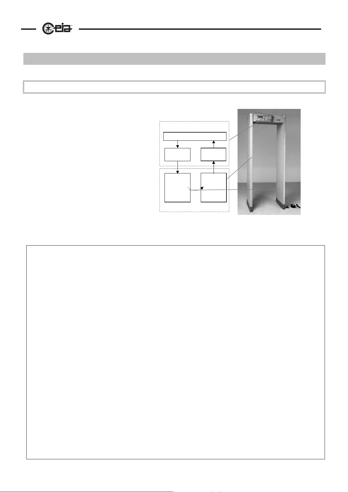
In general, a modern Metal Detector for checking people in transit comprises:
• An electronics unit, made up of:
5
• a variable magnetic field
generator
• a receiver
• a processing and control unit,
Generator
which determines if the variation
of the received signal is due to
metal masses in transit of a
certain shape, volume or
Transmitter
Antenna
composition
• a transceiver antenna in the
form of an archway
Fig. I-1: general block diagram of a metal detector
SOME HELPFUL GUIDELINES FOR METAL DETECTORS
The parameters which best characterise a Metal Detector are as
follows
• Discrimination: This parameter reflects the variation in
sensitivity between potentially dangerous metal objects (due to
their particular shape compared with their volume) and personal
effects (such as coins, keys, watches, buckles, etc...). When a
detector with low discrimination is used, personal effects can
cause a large number of false alarms, rendering the system
ineffective in practical terms.
• Uniformity in detection efficiency: This parameter is closely
connected with the linearity of the magnetic field generated
inside the Metal Detector. Generally speaking, the greater the
uniformity, the better the discrimination.
• Sensitivity: alarm activation threshold: the greater the
sensitivity, the smaller the metal mass which will cause an
alarm.
• Interception speed: the transit speed of a person through the
metal detector archway usually depends on situational factors,
and can vary considerably. The sensitivity of a good Metal
Detector should be independent of the speed of transit.
• Programming: C.E.I.A. have designed their Metal Detectors to
include the possibility of selecting the settings of the operational
parameters: this predisposition facilitates both the installation of
the device (rejection of external sources of interference) and
adaptation to the user’s requirements (orientation towards
ferromagnetic and/or non-magnetic metals). This feature is
particularly important in the detection of weapons made of light
metal.
• Immunity to interference: environmental electromagnetic
interference of mechanical or electrical origin is the principal
cause of false alarms, because it augments the effective signal
of the mass to be detected. Particular attention must therefore
be paid to the Metal Detector’s immunity to this type of
interference.
Electronics unit
Processing and Control Unit
Field
Antenna
• Harmlessness to life support systems and storage media: the
• Synchronisation: multiple installations of Metal Detectors are
• Power supply flexibility: wide tolerance range for the input
• Set-up and calibration with respect to the reference sample: a
• Maintenance: a modern Metal Detector generally incorporates
Receiver
Receiver
Antenna
field emitted by the Metal Detector should be below the values
set by international standards which guarantee harmlessness
to life support systems such as pace-makers, adrenaline
pumps etc. Observance of these limits also means that there
is no effect whatsoever on computer-type storage media.
very common (just think of an airport departure terminal). To
allow several Metal Detectors to operate in a restricted area
without influencing each other, it must be possible to
synchronise them without the help of cable connections.
voltage and emergency batteries which cut in automatically
ensure that the Metal Detector continues operating in the case
of variations or cuts in the mains supply.
modern Metal Detector must allow its installation in whatever
environment, without any interference caused by other
external devices. The security level may usually be adjusted
acting on sensitivity: CEIA’s Metal Detectors are also provided
with a special command (IS) allowing the direct selection of
the functioning parameters which determine a security level
conforming to the International Standards.
a self-diagnosis system which identifies any sabotage and
which also signals accidental faults. Modular construction
furthermore allows the faulty parts to be replaced quickly and
easily, thereby minimising the time the device is out of
operation.
Page 6
6
Models
HI-PE multi-zone --- Rev. FI 050 GB 60K10 v2_1
Series
Model Description Standard configuration/Options
HIPE/PTZ
HI-PE multi zone
HIPE /PTZ-WP
Standard panel model
Intended use:
indoor applications
(IP20)
Outdoor panel model
Intended use:
indoor/outdoor
applications
(IP65)
Standard configuration
• Electronics unit in IP20 plastic casing
• IP20 archway with 720mm useful width, equipped
with connection module without emergency
battery
Options
• IP20 archway with 760mm useful width
• IP20 archway with 820mm useful width
• Connection module with emergency battery (30’).
• Photocells for transit counting
Standard configuration (full options)
• Electronics unit in IP65 metal casing
• IP65 archway with 760mm useful width, equipped
with:
• Connection module with emergency battery
(30’)
• Photocells for transit counter
Construction of the Metal Detector
CEIA Metal Detectors are made up of an electronics unit and an archway antenna; the connection between
the two is via two cables (one for the transmitter and one for the receiver ).
Electronics Unit
The electronics unit, which is extremely compact, is available in an shock-resistant plastic casing, with
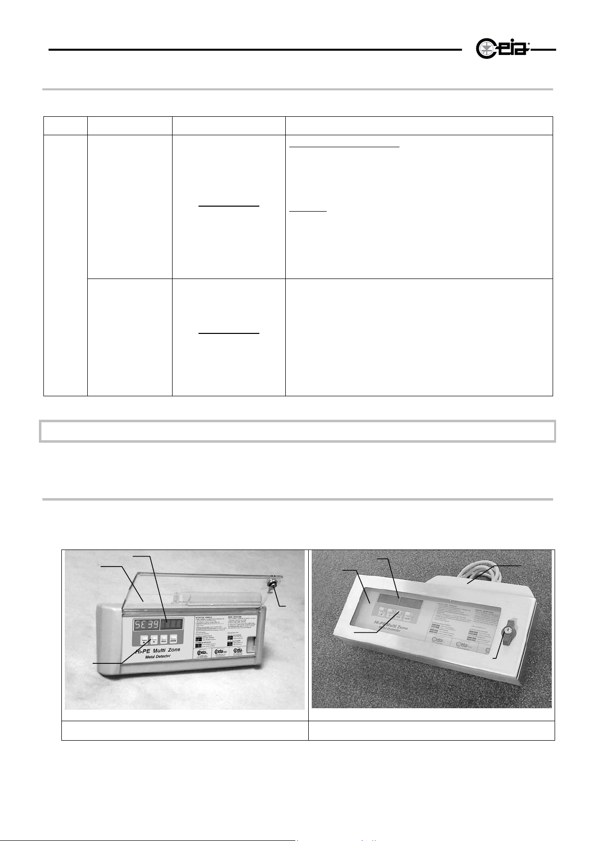
protection grade IP20, or in a tight metal container, with protection grade P55 (for the outdoor model).
Both casings are designed to be attached directly to the crossbar of the archway.
1
4
Fig. I-2a: electronics unit in IP 20 casing Fig. I-2b: electronics unit in IP65 casing
3
1
2
3
4
2
5
The alphanumeric display (3) and the programming keypad (4) are situated at the front, protected by a
transparent panel (1) fitted with a security lock (2). A cover (5) on the top of the unit protects the terminal
board and connectors to which the antenna, power supply, serial and slave connections are made.
Page 7
HI-PE multi-zone --- Rev. FI 050 GB 60K10 v2_1
Archway
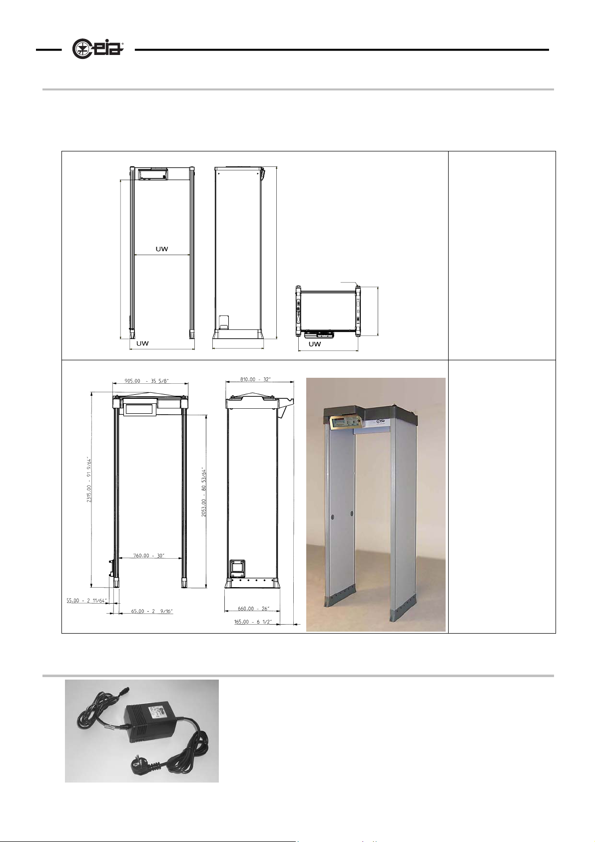
This model is for the most part employed airports, ports, embassies, military installations, manufacturing
premises and stadiums. The panels are manufactured in exceptionally robust synthetic material.
The archway incorporates two bars which light up in the case of an alarm to show the height at which the
metal mass has been detected.
EU
/4)
3
2050 (80"
RX
t
+ 115 (4"1/2)
TX
660 (26")
/4)
3
2255 (88"
+ 50 (2")
ø 6.5 (ø1/4")
/4)
3
630 (24"
UP
EU
TX
t
RX
LP
Standard Model
EU electronics unit
RX receiver panel
t cross-bar
TX transmitter panel
UW = 720mm (760mm or
820mm optional)
Fig. I-3a Dimensions
Outdoor Model
(for outdoor
applications)
EU electronics unit
LP protection of the
lower connection
module
RX receiver panel
t cross-bar
TX transmitter panel
UP upper protection
UW =760mm
Fig. I-3b Dimensions
7
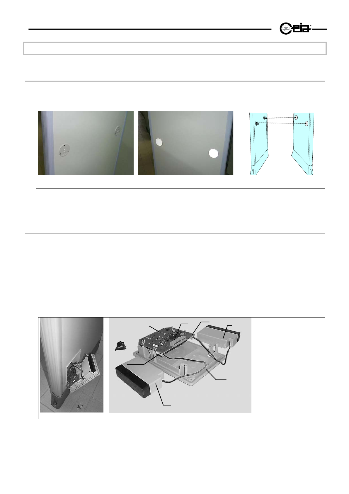
Mains adapter
Input voltage: 230Vac (CEE plug) or 115Vac /100Vac (UL plug)
Dimensions: 121 x 80 x 71 (LxWxH)
Cable length - plug side: 2m
Cable length - electronics unit side: 2m
Weight: 1,5 kg.
Protection degree: IP30
Fig. I-4
Page 8
8
HI-PE multi-zone --- Rev. FI 050 GB 60K10 v2_1
OPTIONS
Transit counter
Two photocells fitted into the antennae allow counting of transits, alarms and percentage of alarms.
TX
RX
RXTX
Fig. I-5a Photocells
Fig. I-5b Reflectors
Emergency batteries
Two 12V-0,8Ah batteries built into the antenna switch in automatically and allow about 30 minutes of
independent operation in the event of a mains failure. The batteries recharge automatically when the metal
detector is connected to the AC power supply and switched on.
Use of the emergency batteries is signalled by a flashing letter "B" on the electronics unit display. Recharge
time is about 8 hours.
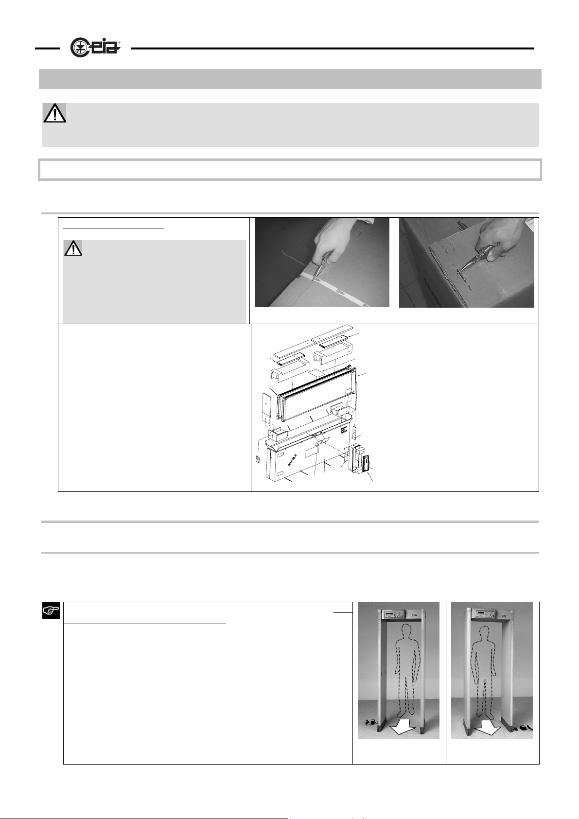
The batteries (2) are housed in a compartment located in the upper part of the TX panel and are connected
to the recharging card AB via the connectors (4).
3
4
5
2
4
2
1
1
cover
2
batteries (model NP
0.8-12 Yuasa)
3
card ALP (battery
charger)
4
battery connectors
5 connector for internal
connections
Fig. I-6
Page 9
HI-PE multi-zone --- Rev. FI 050 GB 60K10 v2_1
A
II - INSTALLA TION
Before proceeding to install the device read the warnings and instructions in this section and in the
paragraph “Installation, use and safety information” carefully. Please note that CEIA is not responsible for
any damage that may result from installations that do not follow these guidelines.
Assembly
Unpacking the Metal Detector
Opening the packaging.
Cut the bands with scissors and
open the top side of the box.
Before taking out the components,
remove the staples that join the
strips of cardboard with pincers to
avoid injury or damage to the
equipment.
Handle the material with care during
unpacking operations, to avoid injury to
people or damage to the equipment.
All accessories needed for assembly of
the Metal Detector are supplied with the
device
tr2
tr1
RX
PL
CA
M
TX
PL
CH
IK
EU
CA customer address
EU electronics unit
IK installation kit
M manual
PL list of materials
RX receiver panel
tr1 cross-bar
designed for
fixing the
electronics unit
tr2 second cross-bar
TX transmitter panel
9
Mechanical assembly
Assembly of the probe
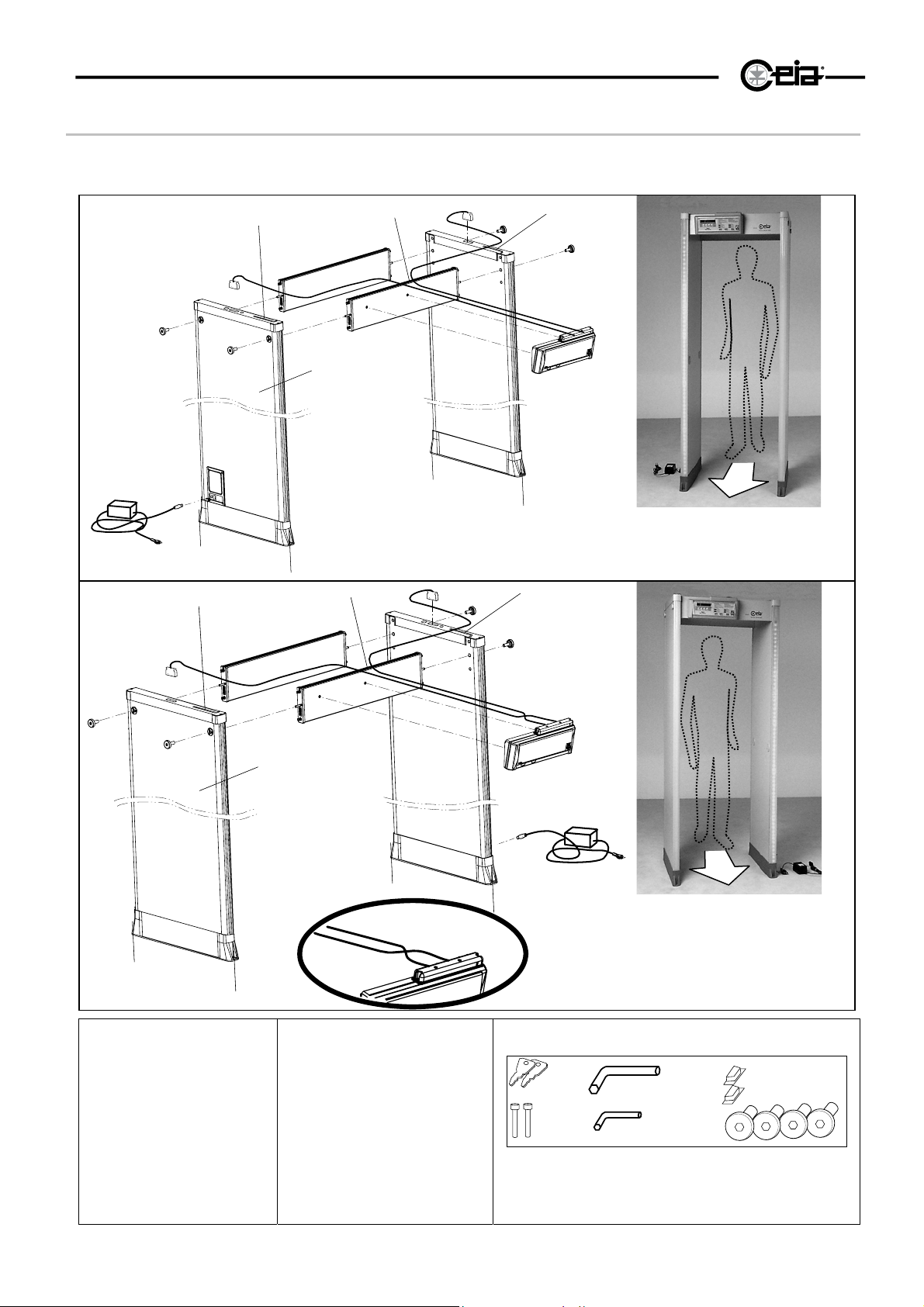
Refer to figures II-1a and II-1b. Connect the panels to the cross-bars tr, using the wrench provided to tighten
the screws vt fully (about 15 Nm). The transmitter panel (TX) can be recognised by the connector at the
bottom..
The probe can be assembles in two different configurations, both
having the same level of performance:
• configuration A (with TX panel on the left when facing the
exit side)
• configuration B (With TX panel on the right when facing
the exit side)
The choice between the two configurations should be made based
on installation requirements: see notes on the following pages (in
particular, the paragraphs “Application in an airport
environment”
and “Installation of coupled metal detectors - synchronisation”).
TX
PSA
Configuration A
TX on left
RX
RX
Configuration B
TX on right
TX
PS
Page 10
10
A
HI-PE multi-zone --- Rev. FI 050 GB 60K10 v2_1
Fixing the electronics unit
Refer to figures II-1a and II-1b. Fix the electronics unit EU to the cross-bar tr1 using the wrench provided to
tighten the screws vc fully (about 1.2 Nm).
cc
Ctx
tr2
cp2
vc
Crx
cc
vc
cc
vt
vt
PSA
vt
vt
BD2
ca
cp1
TX
BD1
tr1
RX
EU
TX
RX
PSA
Configuration A: TX on left
Fig. II-1a
Ctx
cc
Crx
vt
vt
tr2
RX
cc
cp2
vc
vc
tr1
BD1
cc
vt
vt
BD2
TX
EU
RX
BD1, 2 LED bar
ca power-supply cable
cc central cable fixing
groove
CH chip card
cp1 lower connection module
cp2 upper connection module
Crx RX panel – electronics
unit cable
Ctx TX panel – electronics
unit cable
EU electronics unit
TX
PSA power supply adapter
RX receiver panel
tr1 cross-bar designed for fixing
the electronics unit
tr2 second cross-bar
TX transmitter panel
vc electronics unit fixing screws
vt cross-bar fixing screws
PSA
ca
cp1
PS
Configuration B: TX on right
Fig. II-1b
Control unit
keys
Screws for
the control
unit
Allen wrench for
crossbar
Allen wrench for control
unit
RS232 connector
covers
Cross-bar fixing screws
Installation kit
Page 11
HI-PE multi-zone --- Rev. FI 050 GB 60K10 v2_1
•
•
Positioning
Transit requirements
The Metal Detector will be positioned, according to the requirements dictated by the transit, in such a way as
to allow the maximum flow of people and observance of the rules for installation.
See notes on the following pages for correct positioning.
Minimum distances - Electrical and mechanical compatibility
General Rules
:
- avoid movement of significant metal masses less than 70 cm from the Metal Detector antenna;
- avoid the presence of electric lines and electrical devices less than 30 cm from the metal detector probe,
especially the receiver section (RX).
- move electrical/electronic devices (e.g. motors or switching power supplies) in general away from the
metal detector probe, especially the receiver section (RX): the distance depends on the type and power
of the device.
11
The distances mentioned are indicative only
IMPORTANT!
:
The amount of interference should be assessed at the time of installation (see paragraph “Installation
Check”).
----
…
*
no signal or one green asterisk: interference acceptable!
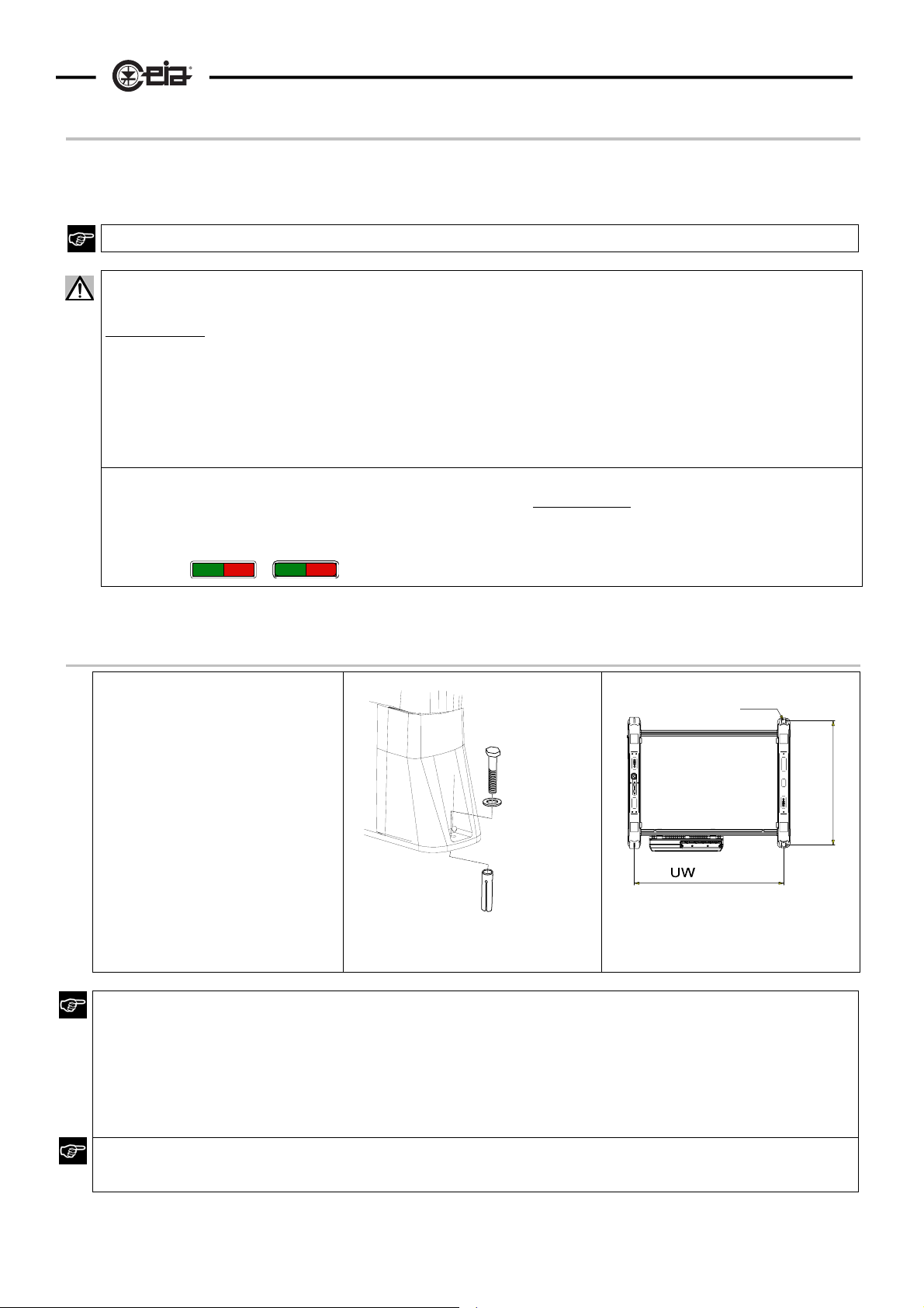
Fixing the antenna to the ground
To fix the antenna to the ground
screw the expansion screws (vf)
vf
into the floor through the holes
provided in the base flanges.
Carefully check the
perpendicularity and alignment of
the transmitter and receiver
sections, ensuring that they are
anchored at the right distance
Fig. II-2a
UW= 720/760/820mm
Fig. II-2b - Diagram of holes for
fixing to ground
Stability
To operate properly the antenna should not be subject to shocks or movements. Follow the installation
instructions and ensure that the Metal Detector probe is stable and anchored firmly to the ground using screws
or silicone. Check the rigidity of the floor; in particular, avoid installation on:
Wood floors
"technical"-type floors, as these generally do not rest on surfaces which guarantee stability over their whole
area.
ø 6.5 (ø1/4")
+ 50 (2")
/4)
3
630 (24"
Holes
It is strictly forbidden to make holes in the Metal Detector antenna or to insert screws in positions, or of lengths,
not expressly indicated by CEIA. Damage due to such actions is not covered by the product warranty.
Page 12
12
HI-PE multi-zone --- Rev. FI 050 GB 60K10 v2_1
Electrical assembly
All connecting cables between the gateway and the power supply or other external devices must be properly
fixed and protected so as to achieve the best performance from the detector and avoid accidental injury to
people who might trip over them.
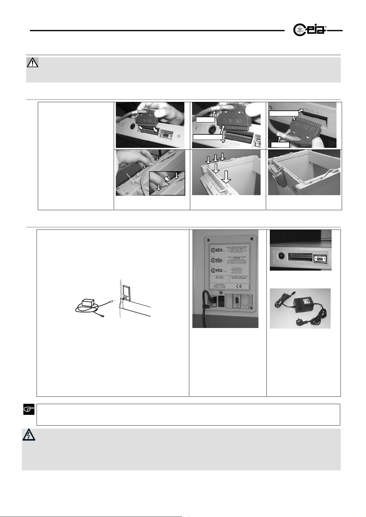
Connecting the electronics unit to the archway (antenna).
• Refer to figures II-1a
and II-1b.
The electronics unit is
fitted with two cables for
connection to the
antennae (Crx for the
receiver panel, Ctx for
the transmitter panel).
The connectors of the
receiver and transmitter
panels are located on
the top of the units.
• Attach the cables to the
cross-bar using the
grooves (cc) provided.
Ctx
60xxx t
TX ANTENNA
cc
Fig. II-2c
RX ANTENNA
Crx
60xxx r
Power supply connection
Refer to figures II-5a e II-5b.
The TX panel incorporates a low-voltage power-
cp1
supply section: the connection panel (cp1) is located
low down, and, in addition to the power-supply
connection socket DC, includes the connector for
serial communication (B PORT). The mains power
adapter PSA should be connected to connector DC.
DC
L1
B-PORT
S1
PSA
ca
cp1
The connections panel is also designed for the
insertion of two emergency batteries (see Options
section).
The panel Metal Detector is provided with an
additional connection module located in the upper
part of the TX panel (cp2): this allows the
connections to be made via cables coming down
from the ceiling
.
B-PORT serial communication
port
cp1 lower connection
module
DC power-supply cable
connector
L1 power indicator
S1 On/Off switch
Fig. II-2d
Check that the voltage supplied by the mains corresponds to the detector’s supply voltage: this latter is
indicated on the device’s power supply adapter and on the test report at the end of this booklet.
The use of a different mains voltage may damage the equipment
!
cp2
TXc
DC
ca
ca power supply cable
cp2 upper connection
DC power-supply cable
PSA power supply adapter
T- PORT serial communication
TXc TX panel connector
module
connector
port
for cable connecting
the control unit to the
TX panel
T-PORT
PSA
The standard power-supply adapter is not waterproof: place it in a well-ventilated position where it is protected
from water (rain, condensation, liquid detergents).
A protection switch should be connected up between the mains supply and the detector. The external
grounding line should conform to standards and should not in any case have a resistance greater than 3
Ohm.
Auxiliary connections: see appendix.
Page 13
HI-PE multi-zone --- Rev. FI 050 GB 60K10 v2_1
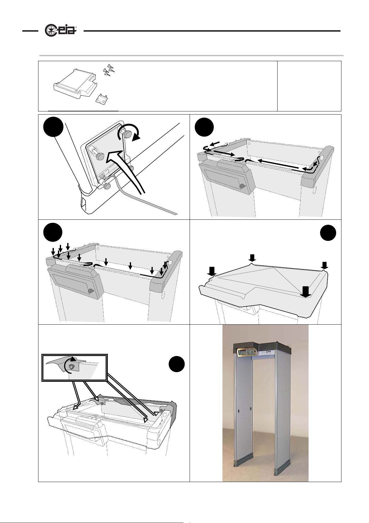
Outdoor model for outdoor applications: assembly
A
1
C
A: upper protection
B: lower connection module protection
B
B
C: threaded knobs
2
13
Kit composition
3
4
A
5
C
A
Page 14
14
HI-PE multi-zone --- Rev. FI 050 GB 60K10 v2_1
Examples of Installations
Application in an airport environment
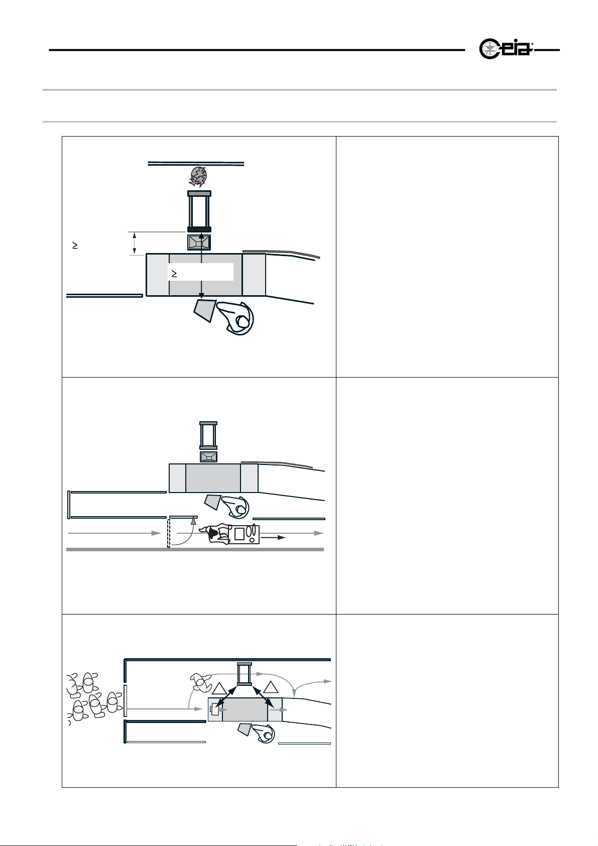
RX
RP
40cm!
40cm!
MD
TX
TP
100cm!
XR
MO
The following notes refer to an airport departure
terminal equipped with an X-ray unit for
personal effects and a metal detector to
intercept any weapons carried by passengers.
Siting of the devices
Care must be taken in the siting of the
devices to avoid electromagnetic interference.
The RX antenna of the MD metal detector
should ideally be located as far as possible from
the monitor (MO) and conveyor belt of the X-ray
inspection device (XR).
Site the transmitter antenna (TX), recognisable
by its power-supply connector, next to this
device.
Auxiliary passage
Wherever possible provide a passage dedicated
to service personnel transit (AP), which will
allow the passage of material and equipment for
the cleaning and maintenance of the area.
It will not therefore be necessary for the staff to
pass through the Metal Detector, and the
possibility of accidental blows and damage to
the detector will be avoided
AP
MD1
WL
!
XR
!
Movement of luggage
In order to avoid false alarms from the metal
detector due to movement of luggage near the
archway, it is advisable to locate it at equal
distance from the beginning and end of the
conveyor belt, where the luggage is taken back
by passengers. It is also advisable to stop
passengers crowding into the entrance by
placing channelling barriers near the access
control system (WL: waiting line).
Fig. II-3
Page 15
METAL
HI-PE multi-zone --- Rev. FI 050 GB 60K10 v2_1
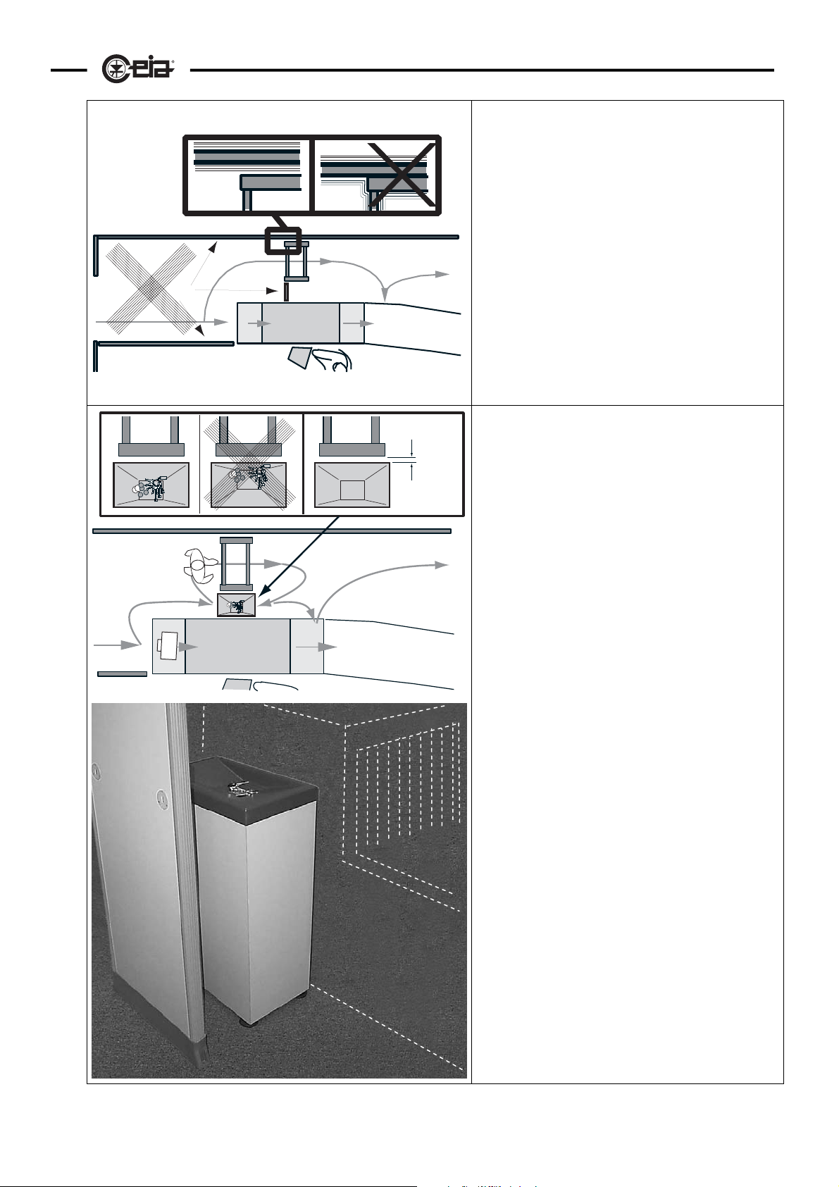
Barriers
It is recommended that the barriers be made of
insulating material (wood, glass, lexan, plastic
panelling, cordons, architectural embellishments
in insulating materials), so that any movement
due to knocks do not affect the antenna of the
metal detector.
MD1
XR
MD1
~2cm
OHT
XR
For the same reason, avoid direct contact
between the barriers and the probe of the metal
detector.
CEIA Personal Effects Depository
We recommend placing a CEIA Personal
Effects Depository (OHT) between the metal
detector probe and the X-ray unit
This article acts both as a spacer between the
X-ray unit and the metal detector and as a
temporary depository for metal personal effects
which are not of dubious nature and therefore
not required to undergo X-ray analysis (coins,
keys and so on).
In this case, again, avoid direct contact between
the depository and the metal detector probe.
Fig. II-3b
15
Page 16
16
HI-PE multi-zone --- Rev. FI 050 GB 60K10 v2_1
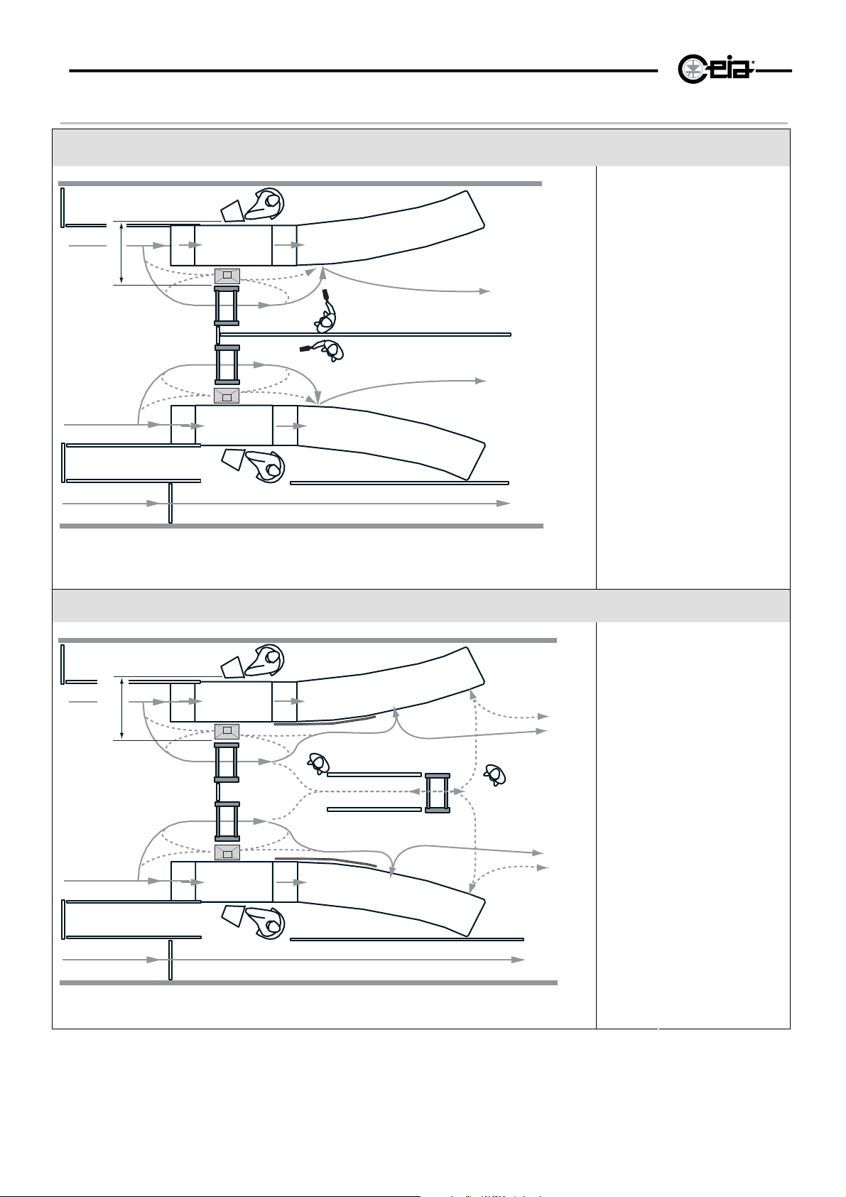
Transit flow-rate and secondary metal detector for inspection in case of alarm
Medium-low flow-rate application: manual secondary metal detector
Should the alarm sound, locate
and identify the metal objects
being carried by making the
person pass through the gate
several times or, if necessary,
by using the hand-held metal
detector.
Possible transit for
AP
service personnel
HHMD
Hand-held metal
detector
MO
Monitor of the X-ray
unit
OHT
CEIA Personal Effects
Depository
PrMD
Primary metal
detector
02PN10
RX
Receiver antenna
TX
Transmitter antenna
XR
X-ray unit
Fig. II-4a
>100
PrMD
PrMD
MO
XR
OHT
TX
HHMD
HHMD
TX
OHT
XR
MO
AP
CEIA PD140
HI-PE or
High flow-rate application: secondary metal detector with zonal detection
MO
XR
>100
PrMD
PrMD
Fig. II-4b
OHT
TX
SeMD
TX
OHT
XR
MO
AP
Should the alarm of the primary
metal detector sound, locate
the metal objects being carried
using the secondary metal
detector.
Possible transit for
AP
service personnel
Monitor of the X-ray
MO
unit
OHT
CEIA Personal Effects
Depository
PrMD
Primary metal
detector
02PN20
RX
Receiver antenna
SeMD
Secondary metal
detector
interception zone
TX
Transmitter antenna
XR
X-ray unit
HI-PE or
PMD2 with
Page 17
HI-PE multi-zone --- Rev. FI 050 GB 60K10 v2_1
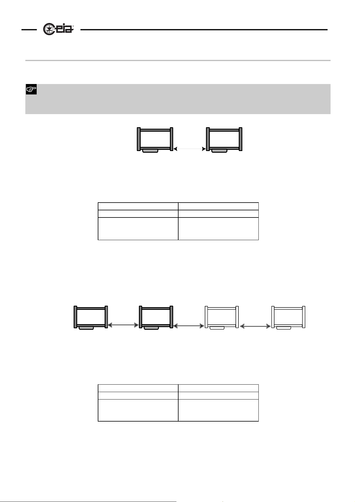
Installation of coupled metal detectors - synchronisation
When two or more Metal Detectors are to operate near each other (generally within 10 meters), they must be
synchronised by choosing an appropriate transmission channel for each one (CH function).
1. Follow precisely the arrangement of the TX and RX antennas and the minimum distances indicated. The
TX antenna can be recognised by the power supply connector.
2. Select the 0 setting for the NL function.
TX
RX
d
17
MD1
50Hz power supply 60Hz power supply
MD1 MD2 MD1 MD2
CH=1 CH=2
Fig. II-5a Installation of 2 Metal Detectors
TX
d
RX
RX
MD2
NL = 0 !
d ≥ 5cm
CH=51 CH=52
TX
d
TX
RX
d
MD1
Fig. II-5b Installation of three or four Metal Detectors
RX
50Hz power supply 60Hz power supply
MD1 MD2 MD3 MD4 MD1 MD2 MD3 MD4
CH=1 CH=2 CH=3 CH=4
MD2
TX
MD3
NL = 0 !
d ≥ 15cm
CH=51 CH=52 CH=53 CH=54
RX
MD4
TX
Page 18
18
HI-PE multi-zone --- Rev. FI 050 GB 60K10 v2_1
III - SWITCHING ON AND DISPLAY MESSAGES
Before working with the device read the warnings and instructions in this section and in the paragraph
“Installation, use and safety information” carefully. Please note that CEIA is not responsible for any
damage that may result from installations that do not follow these guidelines.
Switching on the Metal Detector
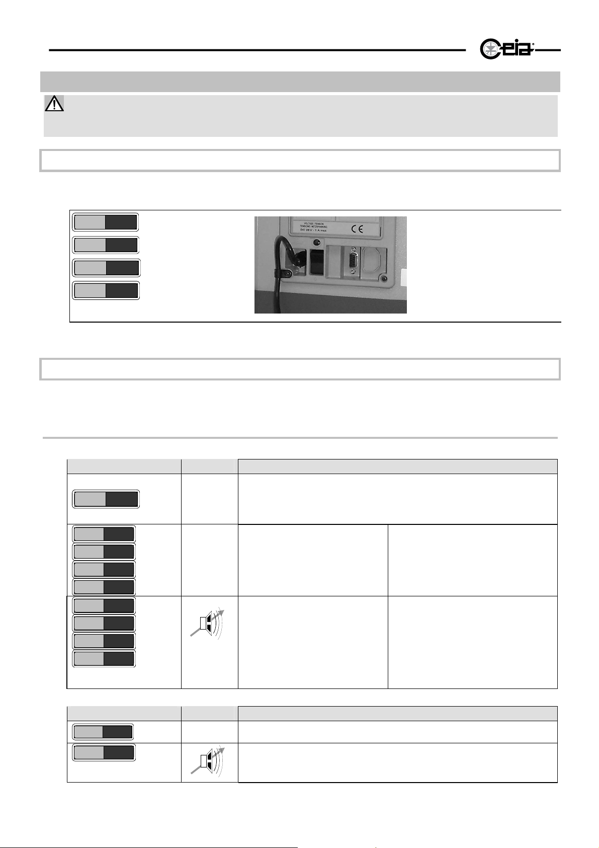
After turning ON the equipment, an audible signal will sound and the display of the electronics unit will show
the following information:
L1 power supply LED indicator
S1 On/Off switch
Fig. III-1b Detail of the lower
connection module
HIPE-PTZ
- - - -
Fig. III-1a
CEIA
****
Manufacturer
Model
Alarm indication test
Normal operating
L1
S1
Display messages
During operation the following messages may appear on the display (see also AD command, Programming
section).
Alarm indications
Messages with AD =0P-5P (see Programming section).
Display Buzzer Meaning
- - - -
*
**
***
****
Fig. III-2
*
**
***
****
AD
small metal mass O
O
medium metal mass O
medium metal mass O
O
O
large metal mass O
NORMAL FUNCTIONING
without metal masses in transit
O
metal mass under the alarm threshold
metal mass over the alarm threshold:
duration of alarm indication determined
by the value of AD.
Messages with AD =0C-5C (see Programming section).
Display Buzzer Meaning
SE31
Fig. III-3
****
AD
Normal operation or metal mass under the alarm threshold (sensitivity indication)
Metal mass over the alarm threshold: duration of alarm indication determined by
the value of AD.
Page 19
HI-PE multi-zone --- Rev. FI 050 GB 60K10 v2_1
Other messages
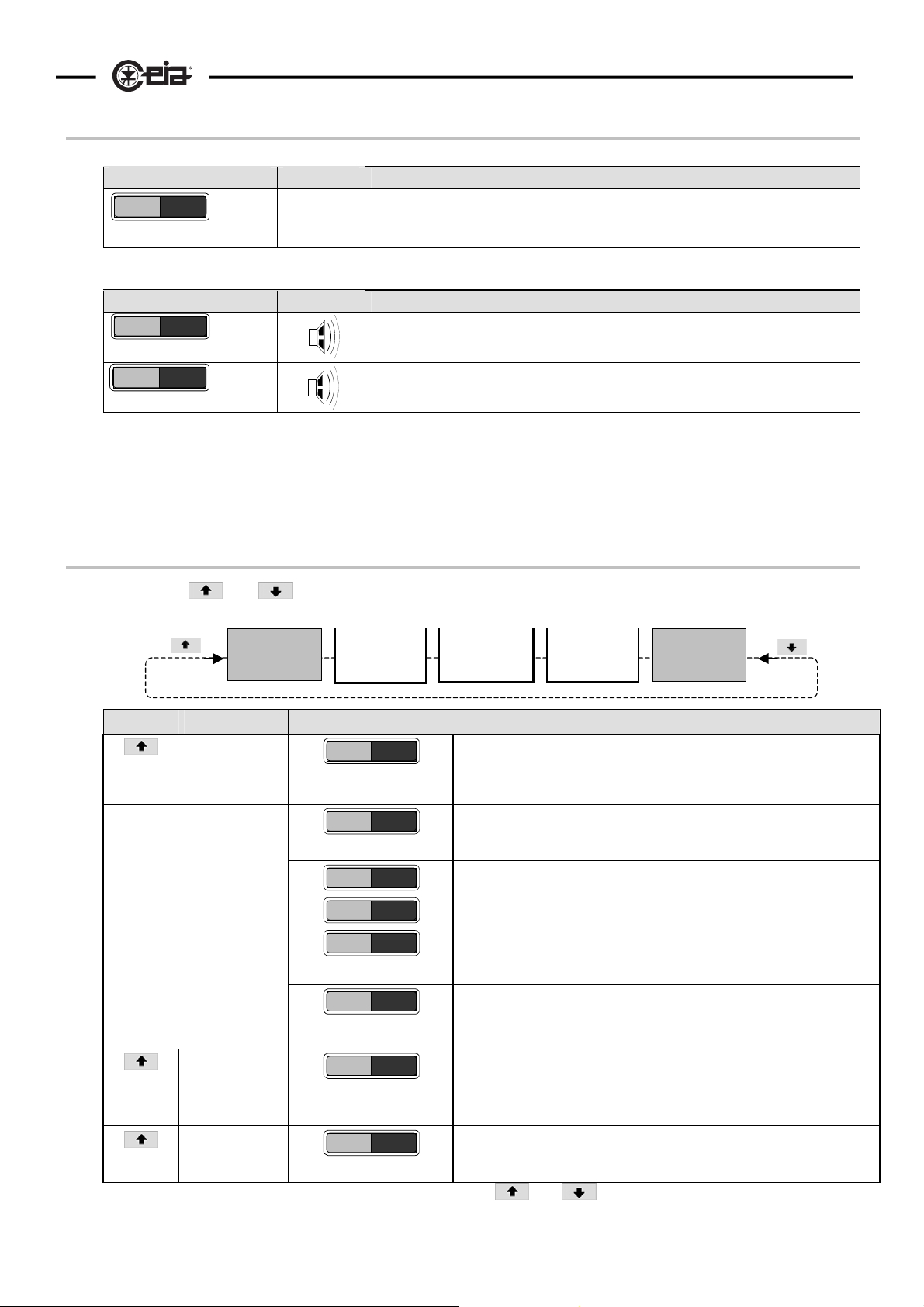
Emergency battery power – mains voltage absent
Display Buzzer Meaning
- - - - B
Fig. III-4a
Warnings
Display Buzzer Meaning
GATE EV
WAIT
Fig. III-4b
-
Emergency battery power supply is only indicated by a flashing letter “B” on the right of
the display.
Self-diagnosis (example shows message indicating antenna damaged or disconnected
from the electronics unit)
Implementation phase of operating parameter modification. Metal Detector not
operational (alarm relay activated).
19
Messages activated via the keypad
When keys or are pressed, the display shows, in sequence, the values of some operating
parameters without having to enter programming mode (see also Programming section).
Normal
operation
indicator
Action Parameter Possible messages
AU
(Autoset)
IS
(International
security
standards)
CI
(Count in)
CO
Fig. III-5
N.B.: the messages described above remain activated until the or key is pressed: this allows the operator to
check, for example, the number of inward transits over the whole shift.
(Count out)
Securit y level
AUTOSET
NILECJ 1
NILECJ 1
MODIFIED
NILECJ 1
:
NO SET
C I 102
CO 15
Number of
inward transits
Standard operation obtained via the AU (Autoset) function.
N.B.: the AUTOSET function is pre-set in the factory for all detectors.
Operation in line with standard NILECJ 0601.00, level 1, obtained via the
IS (International Security Standards) function.
For the other possible settings, see Programming section.
Operation in line with standard NILECJ 0601.00, level 1, obtained via the
IS (International Security Standards) function, but with sensitivity setting
modified (parameter SE).
The two messages alternate on the display.
Operation differs from the standards selectable using the AU and IS
functions. In addition to the sensitivity, it is possible to adjust another
parameter which influences the response of the detector to metals (see
sub-section “Received signal parameters” in the Programming section).
Number of transits through the gate in the direction defined by parameter
GD (gate direction).
The read-out is updated in real time.
Number of transits through the gate in the opposite direction to that defined
by parameter GD (gate direction).
The read-out is updated in real time.
Number of
outward
transits
Normal
operation
indicator
Page 20
20
HI-PE multi-zone --- Rev. FI 050 GB 60K10 v2_1
Visual alarm zone indication
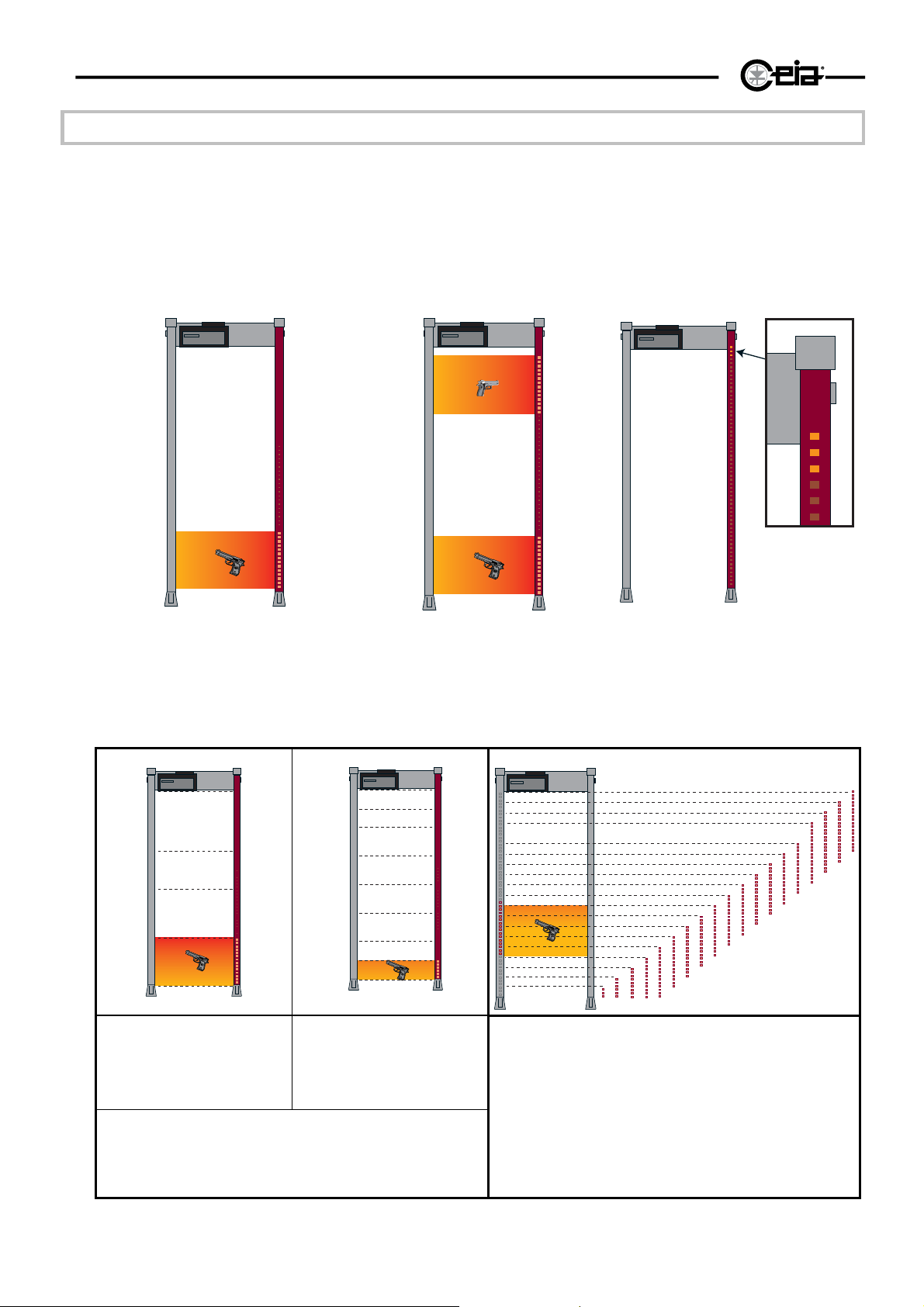
The special feature of this model is that it indicates the height of the metal mass intercepted inside the
archway by means of the LED bar located on the transmitter antenna. In the case of an alarm, one or more
groups of the lights that make up the bar will come on to indicate the zones in which the metal masses have
been detected.
Under non-alarm conditions, a power-indicator light (continuous or blinking depending on the value of
parameter BM; see Programming section) can be seen at the top of the bar display.
The panel model has two light bars, the function of which is set by the GD parameter.
Fig. III-6a - alarm indication for a single
metal mass
Fig. III-6b - alarm indication for two
metal masses
Fig. III-6c -power indicator
Three choices of operating mode, floating (standard), 4 fixed zones and 8 fixed zones can also be chosen
using the ZN function (see Programming section).
Fig. III-6d - 4-zone operation
(ZN=4): when a metal mass is
detected, one of 4 distinct
zones, each of fixed height and
position, lights up.
Fig. III-6e - 8-zone operation
(ZN=8): when a metal mass is
detected, one of 8 distinct
zones, each of fixed height and
position, lights up.
Fig. III-6f - Floating-zone operation (ZN=FLOA):. a group of
LEDs lights up at the height of transit of the metal mass (20
different zones of variable height and position).
In fixed-height zone operation, the alarm threshold can
be adjusted individually for each zone using the
settings Z1...Z4 or Z1...Z8 (see Programming section).
Page 21
HI-PE multi-zone --- Rev. FI 050 GB 60K10 v2_1
Stand-by
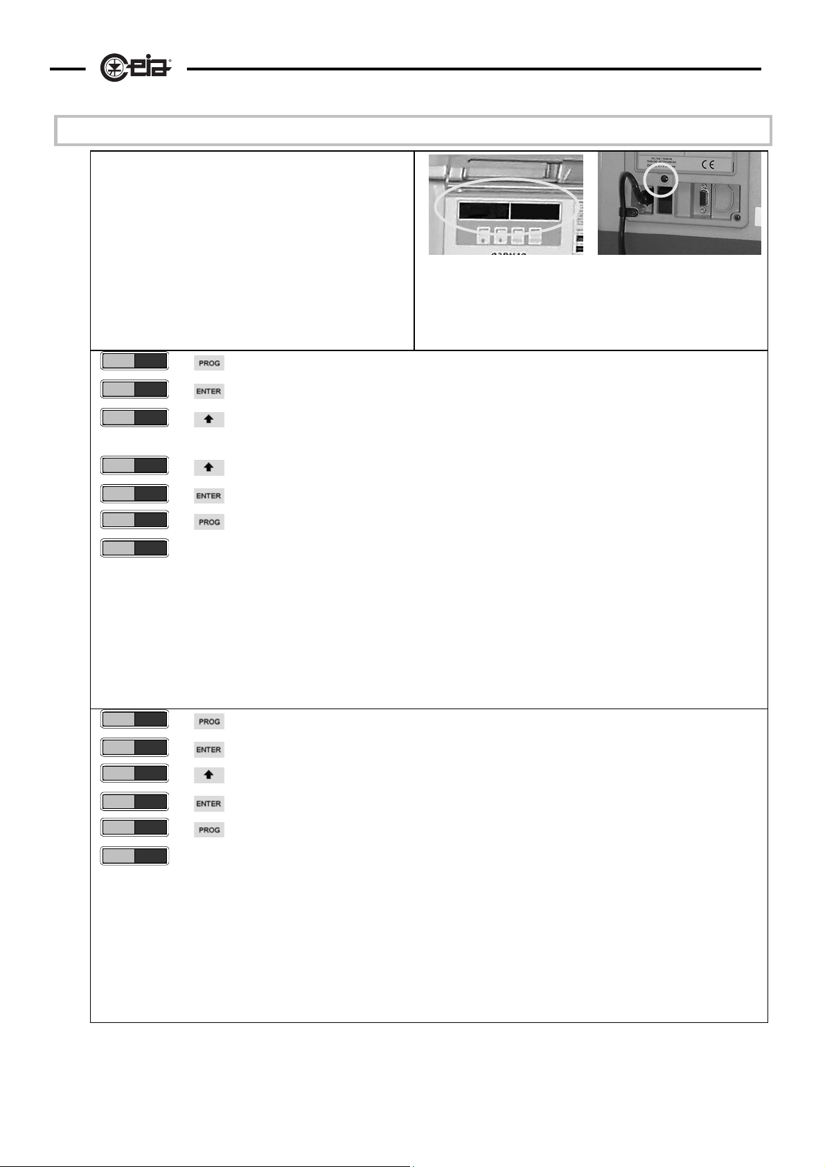
The standard version Metal Detector is not fitted with an
On/Off switch.
To allow deactivation of the detector without
disconnecting it from the power supply, it is fitted with a
software power switch that allows the equipment to be
placed in stand-by condition ( PW function, see also
Programming section).
In this case power consumption is reduced. The
command can also be executed in remote mode (with
metal detectors which are not connected in a network) .
- - - -
- - - - - -
SE =34
:
PW=ON
PW=OFF
PW=OFF
enter the programming phase
press ENTER (enter password, if defined)*
select "OFF" setting using the arrow keys
select PW function using the arrow keys
exit from the programming phase
21
Fig. III-7 – On stand-by the electronics unit display is off, while
the cp1 connection module LED indicator stays on.
switch off
Fig. III-8a switching off the metal detector
enter the programming phase directly
PW=OFF
PW=OFF
PW=ON
PW=ON
Fig. III-8b switching on the metal detector: (always possible without entering the password(s), even if these have been
defined at both user [operator] and super-user [supervisor] level.*)
exit from the programming phase
CEIA
switch on
select "ON" setting using the arrow keys
* See the section “Advanced programming – use of the password)”.
Page 22
22
HI-PE multi-zone --- Rev. FI 050 GB 60K10 v2_1
IV - PROGRAMMING
Before working with the device read the warnings and instructions in this section and in the paragraph
“Installation, use and safety information” carefully. Please note that CEIA is not responsible for any
damage that may result from installations that do not follow these guidelines.
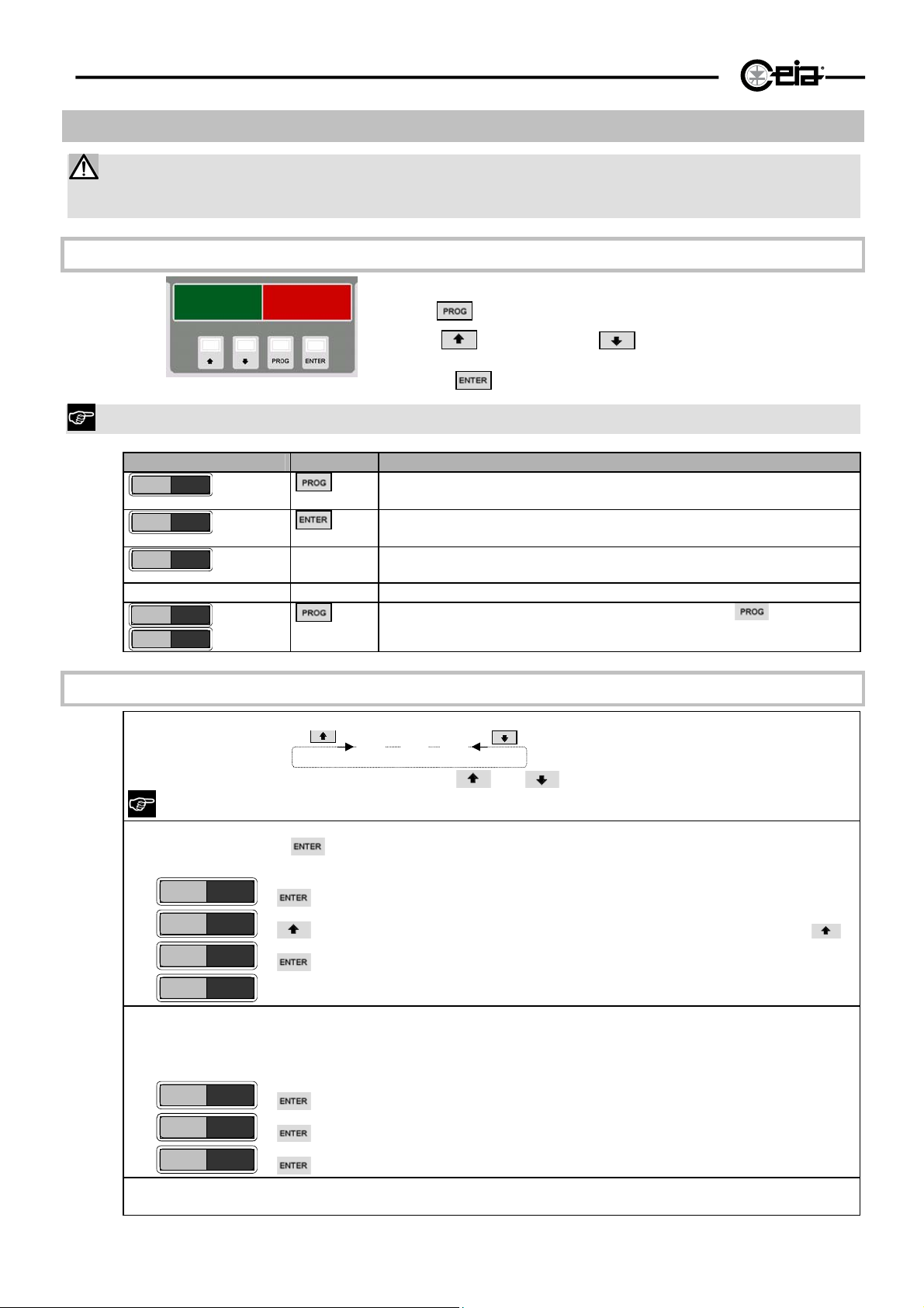
Local programming
Use the keypad on the inside panel of the control unit.
key is used to enter and exit the programming phase.
(increase) and (decrease) keys are used to
key.
Fig. IV-1 display and programming keypad
The
The
choose the function and select the data to enter; confirmation is
via the
During programming, the metal detector is deactivated.
Display Keyboard Action/Meaning
- - - -
- - - - - -
U SE =35
Press PROG key.
Press ENTER key: the last selected function will appear.
programming phase , U: operator (“User”) level (see below).
: - -
U AV = 6
- - - -
The programming phase is ended by pressing the key.
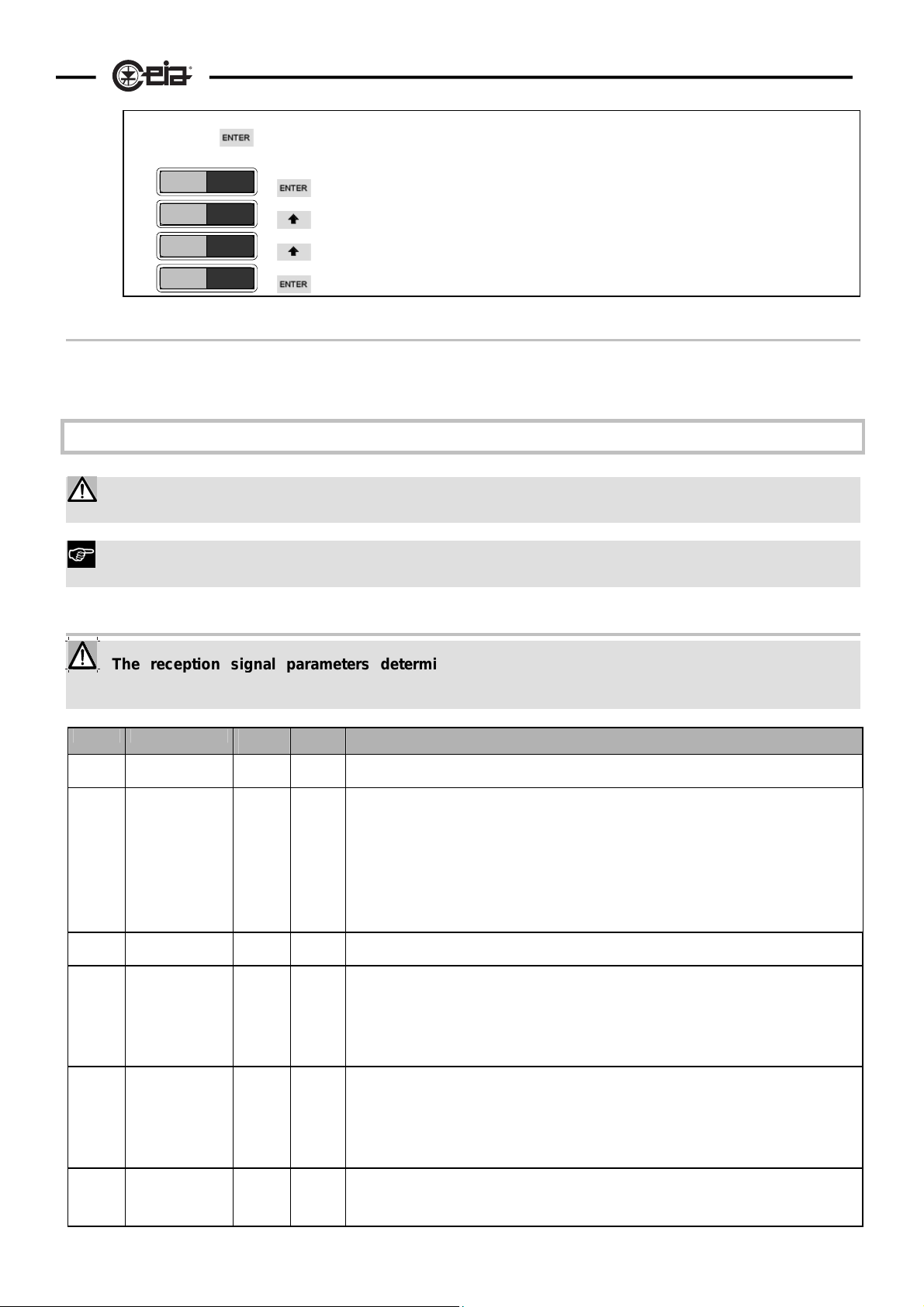
Command execution - Local programming
a) The commands are scanned in a cyclical sequence:
SE
This can occur in two directions by pressing the
DS
LS
and . keys.
Depending on how the metal detector is programmed, only some of the commands may be displayed.
b) Some functions are purely commands and do not have a value assigned to them. In this case the function is
activated by pressing
Example: Counter alarm reset:
U CR
OK ? N
OK ? Y
U CR
Other functions are parameters whose values are altered while the metal detector is in use (e.g. the
command activation
confirmation request: the value changes from N (NO) to Y (YES) by pressing
command execution
return to the sequence of commands
alarm counter). In this case the current value can be read (
exit from the command press ENTER once more.
E.g.: value reading for working time.
U WT
WT 456
U WT
The remaining parameters can be both visualised and modified by the operator (the parameter can
parameter activation
visualisation of the current value (456 hours)
return to the sequence of commands
. Some commands also require confirmation before execution.
status request) by pressing ENTER. To
therefore function as a status request or as a command).The current value of the parameter is
Page 23
HI-PE multi-zone --- Rev. FI 050 GB 60K10 v2_1
;
visualised on the display to the right of the function code. Any modification of the value is activated by
pressing
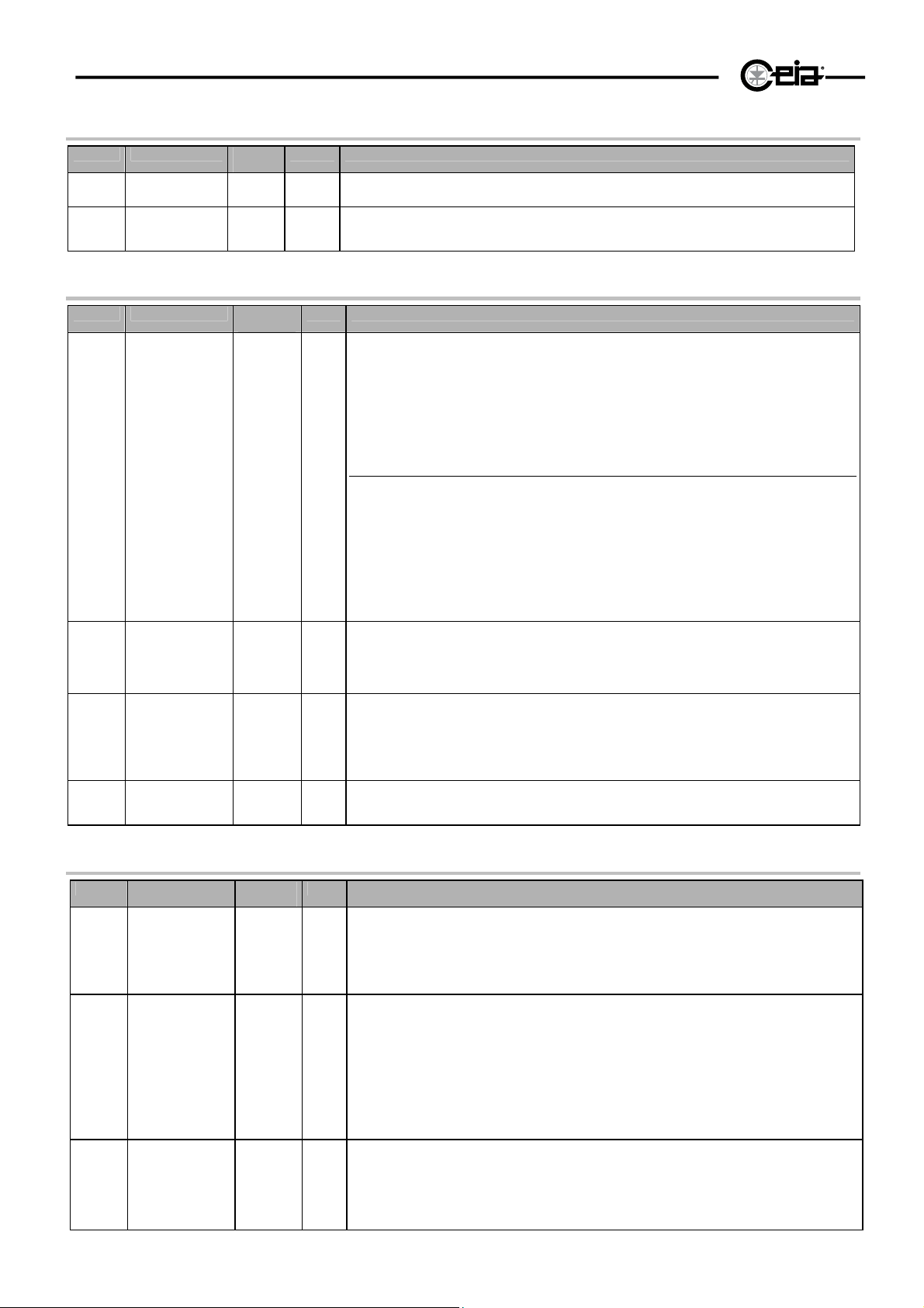
E.g.: modifying the volume of the audible signal from value 4 to value 6.
U AV = 4
U AV = 4
U AV = 5
U AV = 6
.
current value (4) starts flashing
the value increases by one
the value increases by one once more
confirmation of the new value: the value stops flashing
Time out
The programming session will be terminated automatically if no commands are entered for a period of 2
minutes.
Description of the commands
To see the standard values and the full list of the commands available at user level see the TEST
RECORD (Factory Acceptance Test Report) at the end of this booklet ( * : enabled command).
23
Code of the function type :
C= command R= status request S= the command can only be accessed at the supervisor (“Super-user”) level
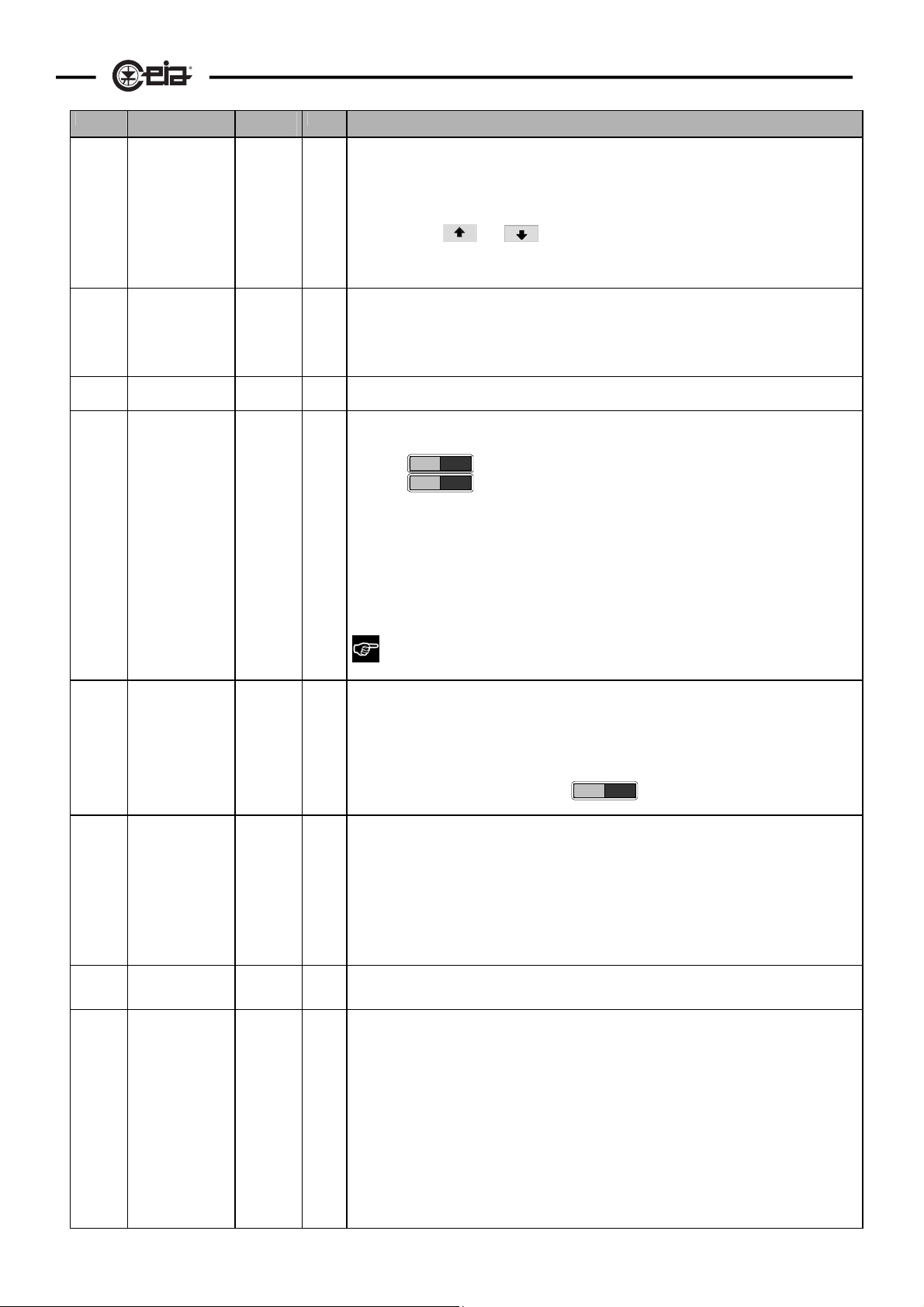
Reception Parameters
The reception signal parameters determine for the most part the Metal Detector’s detection
capability (just consider the sensitivity adjustment). If any variation is to be implemented, it must be
checked for compatibility with security specifications.
Code Meaning
Sensitivity of the
SE
Z1
Metal Detector
Zone sensitivity
adjustment
:
Z8
Minimum
LS
DS
detection speed
Maximum
detection speed
Uniformity
LC
NL
coefficient of the
electromagnetic
field emitted by
the antenna ground level
Noise limitation
coefficient
Possible
values
0-99 C/R 0: minimum sensitivity, detection of large metal masses
-99..+99 C,R In ZN=4 or ZN=8 mode, selects the gain of the individual zone. The rate of
0-9 C/R 0 = minimum limit
0-9 C/R This is correlated to the level of immunity to environmental interference: the lower the
-20,
.
,-1,
0,
1,
.
,20
0-9 C/R 0 automatic attenuation level
Type Notes
99: maximum sensitivity, detection of small metal masses
increase/decrease corresponds to that of the sensitivity setting SE
Ex.: Z3=0 : no correction in zone 3
Ex.: Z3=-15 : reduction of 15 points in the sensitivity of zone 3 relative to the general
sensitivity setting SE.
NOTE: for each zone the sum of the general sensitivity setting SE and of the zonal
sensitivity Zx must be in the range 0 to 99
9 = maximum limit
immunity level, the faster the maximum detection speed. 0 corresponds to the minimum
detection speed (max. rejection of interference); 9 corresponds to the max. detection speed
(min. rejection of interference).
REMARK Decreasing of this parameter must be carried out according to the Security
specifications.
C/R -20 maximum field attenuation
0 no change (standard)
+20 maximum field increment
This command is available on certain probe models only
1 minimum attenuation
9 maximum attenuation
N.B.: setting 0 must be selected if synchronisation between two or more devices is required.
Page 24
24
HI-PE multi-zone --- Rev. FI 050 GB 60K10 v2_1
Transmission parameters
Code Meaning
Transmission
TP
CH
program
Transmission
channel
Possible
values
0-99
0 - 99
Type Notes
C/R To choose a different program from the one pre-set in the factory, contact CEIA’s technical
C/R 0 - 49 for 50Hz power supply
Alarm signal parameters
Code Meaning
Alarm duration 0P-5P
AD
Alarm volume 0-9 C/R 0 (disconnected alarm)
Possible
values
0C-5C
Type Notes
C/R First range: proportional alarm indication
AV
MV
Minimum alarm
volume
Alarm tone 0-9 C/R
0-9 C/R/S 0 (disconnected alarm)
AT
department.
50 - 99 for 60Hz power supply
0P reset time = 0,3 s
1P reset time = 1 s
2P reset time = 2 s
3P reset time = 3 s
4P reset time = 4 s
5P reset time = 5 s
In this case the display will always provide an indication proportional to the metal mass in
transit, using the red sector on the right when there is an alarm.
Second range: constant alarm indication
0C reset time = 0,3 s
1C reset time = 1 s
2C reset time = 2 s
3C reset time = 3 s
4C reset time = 4 s
5C reset time = 5 s
In this case, during normal operation the display will indicate the selected sensitivity; when
there is an alarm, 4 asterisks light up in the red section on the right.
9 (maximum volume).
During local programming, the device provides an audible signal using the selected tone.
9 (maximum volume).
This determines the minimum value of the AV parameter
In the standard settings this parameter can be accessed by the superuser only
5 different continuous tones ranging from 0 (deep sound) to 4 (high sound)
5 different pulsed tones ranging from 5 (deep sound) to 9 (high sound).
During local programming, the device provides an audible signal using the selected tone.
Management of the Metal Detector
Code Meaning
Serial interface
BR
transmission
speed (Baud
rate)
New password XXXXXX
NP
Number of
AC
alarms detected
Possible
values
110, 150,
300, 600,
1200,
2400,
4800,
9600
X = any
alphanumeric
character
0-999999 R
Type Notes
C/R The change of serial transmission speed becomes operative when the programming
C This selects a new password to allow access the programming phase. The password must
session is terminated using the PE command.
be made up of 6 letters (either upper or lower case) and/or numbers. The password is
displayed to facilitate entry. Once the new password has been entered, it will be
effective immediately.
ATTENTION! For security reasons, once a password has been entered it will no longer be
possible to read it. Should the access code be forgotten, assistance will be required from
C.E.I.A. personnel.
Model HI-PE with photocells
It displays:
• the number of passages through the antenna (P, 6 figures),
• the number of passages with alarm (A, 6 figures)
• the net alarms/passages ratio as a percentage (RR -- ring rate, 2 figures and one
Page 25
Code Meaning
Alarm counter
CR
WT
GN
reset
Working time of
the system
General
environmental
noise
measurement
HI-PE multi-zone --- Rev. FI 050 GB 60K10 v2_1
Possible
values
- C This command requests confirmation
0-999999 R
YES,NO C Displays the value of the signal received by the probe. 100 different values ranging from 0
Type Notes
decimal)
• the total number of alarms (T, 6 figures)
All counters are reset by the CR function.
Note: during local programming, the values are displayed according to a cyclical sequence
by pressing the
Note: Passages carried out in the opposite direction to that selected with the GD function
are not counted.
NOTE There are two counters, one at operator level and one at supervisor level (see
also “Advanced Programming” section): only the counter at the current level of
programming is reset.
to 99 can be displayed. Readings under 6 are also displayed via bar-graph:
Local programming: display of the noise level is activated by selecting "YES" and exiting
from the programming.
Measuring ends when the function is turned off (GN= NO): on exiting from the programming
mode the display will show the normal operating message (sensitivity level).
Remote programming: this function is activated by pressing the ENTER key: the numeric
values will then appear on the right, from 0 to 99, continually updated. To end
measurement, press any key
1 I
6 I I I I I I
and keys.
25
EN
SL
PV
GD
Environmental
electromagnetic
noise
measurement
Self-diagnostic
level
Management
programme
version
Gate direction 1,2,3,4 C,R
YES,NO C Similar to the GN function, but for electromagnetic environmental noise
P, C C,R,S
- R
If both GN and EN functions are activated, function EN has priority.
NOTE: the function is terminated automatically after 2 minutes.
NOTE when the measurement phase is terminated a short beep is uttered and the display
shows the message:
RESTART
P limited programme of checks, (without monitoring of TX, RX and control sections).
C complete programme of checks.
Partial self-diagnosis (SL=P) is useful for technical testing.
In the standard settings this parameter can be accessed by the superuser only
Selects the direction of transit through the antennae relative to the positioning of the
archway and the type of alarm signalling.
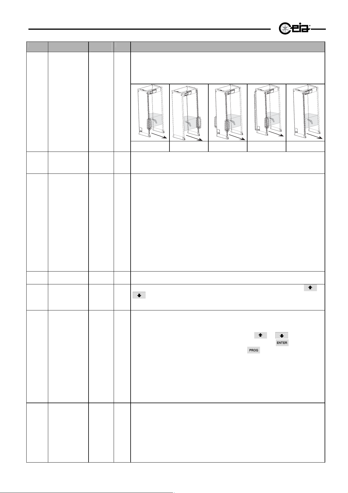
GD=1 if you look at the gate from the point of entry, the transmitter antenna should be on
the right. The LED bar activated is BD1.
GD=2 if you look at the gate from the point of entry, the transmitter antenna should be on
the left. The LED bar activated is BD2.
GD=3 similar to GD=1, but both LED bars are activated.
GD=4 similar to GD=2, but both LED bars are activated.
GD=5 similar to GD=1, but in the case of an alarm LED bar BD1 identifies the metal
mass, whilst bar BD2 lights up completely.
GD=6 similar to =2, but in the case of an alarm LED bar BD2 identifies the metal mass,
Page 26
26
Code Meaning
Possible
values
HI-PE multi-zone --- Rev. FI 050 GB 60K10 v2_1
Type Notes
whilst bar BD1 lights up completely.
GD=7 similar to GD=1, but both LED bars are deactivated.
GD=8 similar to GD=2, but both LED bars are deactivated.
7;
(8
%'
%'
(8
%'
%'
%'
(8
%'
%'
(8
%'
(8
%'
%'
BM
ST
LD
IS
UP
AU
LED bar
operating mode
Stores a set of
parameters
selected by the
user
Loading stored
parameters
International
Security
Standard
Selects the
commands that
can be accessed
by the user
Autoset
.
CONT
BLIN
1-10 C Each detector is equipped with 10 sets of parameters specifically designed for some of the
1-10 C See function ST.
see the
following
table
Y,N C,S The command codes will be displayed followed by an indication in brackets of the current
- C Selects the factory-set standard values of operating parameters controlled by some
7;
7;
7;
7;
GD=1 GD=2 GD=3 GD=5 GD=7
C,R CONT during normal operation, the top segment of the LED bar on the probe is
C,R
continuously lit.
BLIN during normal operation, the top segment of the LED bar on the probe blinks.
most common applications
The ST command, however, allows another 10 sets of parameters to be stored in memory.
These parameters are set by the user: in order to do so the operator simply programs the
apparatus for the required operational application and then activates the ST command,
assigning an identification number.
From that moment onwards the detector stores that programming set-up in memory and the
operator may retrieve it for use should the programming be modified for any reason.
Obviously, if a set of parameters is recorded under an identification number that is already
in use, the new program overwrites the previous one.
ATTENTION! If a problem occurs in the programming memory, the "PROG" message will
appear and the operation will not be executed.
During normal operation the current Security Level is displayed by pressing the
keys (see the following table).
status: (Y) = activated, (N) = deactivated
Local programming
The status of each command is changed by pressing the
not wish to change the state of the command you need only press
will scroll to show the following command. Press the
procedure
Remote programming (see below)
The state of each command is changed by entering the opposite value to the current one to
the right of the # character. If the user does not wish to change the command state, he/she
can simply press ENTER, and the cursor will move on to the following command. Press "."
to interrupt the selection procedure.
commands.
These standard values make up an additional set of parameters to those numbered 1 to 10
which can be recalled with the LD function.
By executing the AU command the detector will be set to the most generally-used operating
parameters, or alternatively to those which is best suited to a particular type of application
specified by the user (for customised models).
The command only relates to some parameters.
This command requests confirmation.
or keys. If you do
and the display
key to interrupt the selection
or
Page 27
Code Meaning
Output level HEA.C
PO
Serial number of
SN
the Metal
Detector
Power ON/OFF ON,OF C ON metal detector ON
PW
ZN
Number of zones FLOA
HI-PE multi-zone --- Rev. FI 050 GB 60K10 v2_1
Possible
values
ASTM
50364
ACGIH
IEEE
364LO
ENVDE
- R
4
8
Type Notes
R,C The parameter is pre-set in the factory according to the regulations regarding human
exposure to electromagnetic fields. applicable in the destination country. Any modification to
this pre-setting is the responsibility of the installer. For further information contact the
competent bodies. CEIA’s technical/sales department can provide further clarification.
HEA:C Health Canada - Medical Devices Bureau
ASTM ASTM FXXXX-99 "Standard Specification for Field Strength of Hand-Held Metal
Detectors" (U.S.A.)
50364 EN50364:2001 (basic restrictions)
ACGIH American Conference of Governmental Industrial Hygienists-1999
IEEE standard IEEE C95.1-1999
364LO EN50364: 2001 (derivated reference levels)
ENVDE VDE 0848-3-1
OF metal detector on stand-by
For details of the procedure, see the “Use of the Metal Detector” section.
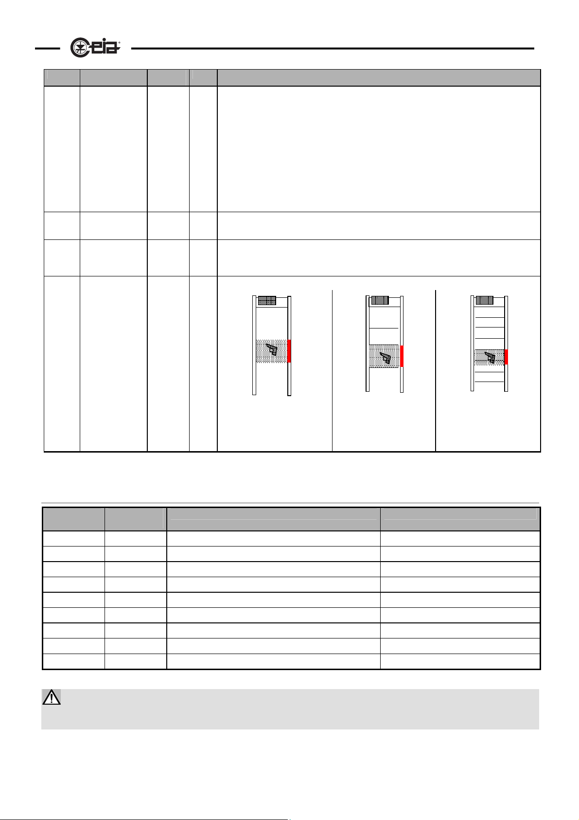
Selects the LED bar signalling mode:
C,R
27
FLOA
a single floating zone: a group
of LEDs lights up at the height
of transit of the metal mass (20
different zones of variable
height and position)
4
when a metal mass is
detected, one of 4 distinct
zones, each of fixed height
and position, lights up.
8
when a metal mass is
detected, one of 8 distinct
zones, each of fixed height
and position, lights up.
ANALYSIS PROGRAMS AVAILABLE WITH THE COMMAND "IS"
PROGRAM
IS
1 NILECJ 1 Standard : NILECJ-STD-0601.00 Security Level 1 AM9
2 NILECJ 2 Standard : NILECJ-STD-0601.00 Security Level 2* AM7; AN7
3 NILECJ 3 Standard : NILECJ-STD-0601.00 Security Level 3* AM5; AN5
4 NILECJ 4 Standard : NILECJ-STD-0601.00 Security Level 4 AM3; AN3; B6
5 NILECJ 5 Standard : NILECJ-STD-0601.00 Security Level 5 AM1; AN1; B2
6 3GUN TST Standard : 3-GUN-TEST (FAA - USA) OTP and weapons foreseen by the Standard
7 3GUN TSE Standard : ENHANCED 3-GUN-TEST OTP and weapons foreseen by the Standard
8 SPH.44.4 - Sphere AISI 420 ø44.45
9 SPH.41.3 - Sphere AISI 420 ø41.275
* N.B.: security levels NILECJ 2 and NILECJ 3 include the additional requirements foreseen by the Standard.
DISPLAY
MESSAGE
SECURITY LEVEL / APPLICATION SAMPLES
The unit is programmed in the factory to ensure operation according to the IS standards for the passage
width listed in the " Factory Acceptance Test Report" included at the end of the manual. If, for any reason, the
passage width has been changed, this correspondence is not guaranteed
Page 28
28
HI-PE multi-zone --- Rev. FI 050 GB 60K10 v2_1
Installation Checks
The operating parameters of each detector are pre-selected in the factory, based on its application. In
general, installation does not cause any particular problems when the tips given in the “General Installation
Instructions” have been followed.
The final user is responsible for selecting the appropriate security level/sensitivity for their
application. After this selection has been made, and programming has been adjusted accordingly, it
is also the final user's responsibility to verify calibration using their selected test object.
Additionally, this test should be carried out periodically to insure no changes have been made to the
equipment.
There follows a guide to the sequence of operations to be followed if the Metal Detector is to operate at
maximum efficiency. After completing the detector’s mechanical installation and electrical connections, switch
it on and proceed as follows:
a) choice of optimum transmission channel (command CH ). In the case of multiple installations, follow the
instructions in the section “Installation of coupled metal detectors: synchronisation”.
b) sensitivity adjustment ( command SE )
The sensitivity is pre-set in the factory according to the type of application. Generally, it is only necessary to check proper
detection of a sample supplied with the device or defined by security specifications
Procedure
• Take the metal mass considered to be the smallest sample to be detected, and make several passages
through the probe. The mass must be passed along the centre line of the archway, changing the
orientation of the sample each time.
• Carry out the test passing the sample at different heights, so as to find the sensitivity level that ensures
interception of the sample over the whole of the useful archway, as defined in the security specifications.
The correct sensitivity setting is the lowest which ensures detection of the sample at all heights and in all
orientations.
c) Specific security level (commands AU, IS and SE):
The detector is delivered pre-programmed in the AUTOSET configuration. If this configuration does not
permit detection of a reference sample defined by the customer, the sensitivity setting SE can be modified.
If a security level specified by international regulations is required, it can be selected via the IS command
(see Programming section). Thanks to CEIA Metal Detectors’ extreme consistency of performance, this
command allows adjustment of the detector to the specifications of the selected standard without having to
carry out the test procedure physically.
d) check for electrical noise. Check that activation of electrical devices around the Metal Detector does not
cause interference: the display should not show more than one asterisk in the green sector
e) check for mechanical noise. Check that the movement of metal masses around the Metal Detector (metal
structures in general, doors, furnishings, trolleys, …) does not cause interference: the display should not
show more than one asterisk in the green sector
*
.
*
.
Page 29
HI-PE multi-zone --- Rev. FI 050 GB 60K10 v2_1
29
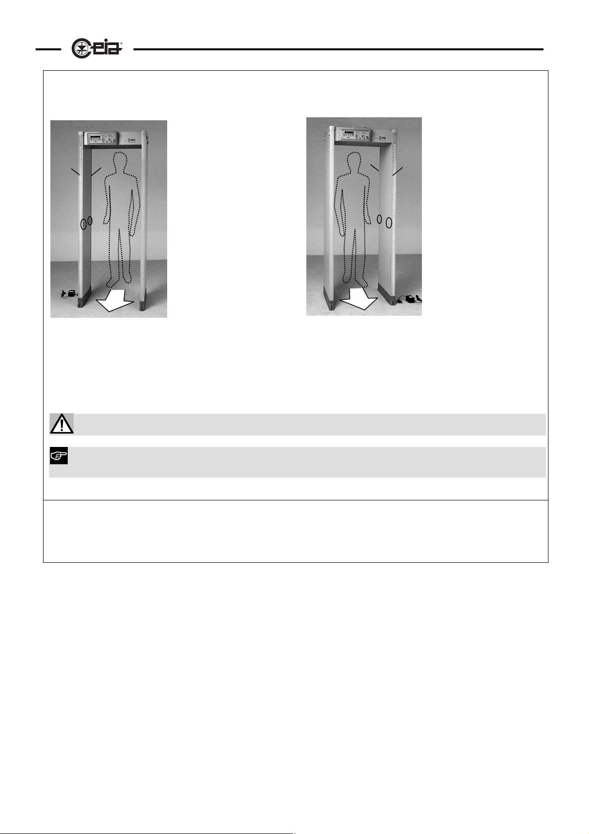
f) Selection of the transit direction (model w ith photocells only - command GD ). Operation of photocells
changes according to the direction of transit through the archway :
TX
BD1
P2
PSA
Fig. IV-2
BD2
P1
in the first case (the TX panel
is on the right hand side as
you pass through) the p1
photocell is at the entrance of
the passage while the p2
photocell is at the exit: select
1 for GD function (see also
GD function, paragraph
"
Management of the Metal
Detector ").
RX
RX
Fig. IV-3
BD1
P2
BD2
P1
In the second case (the TX
TX
panel is on the left hand side
as you pass through) the p2
photocell is at the entrance
while the p1 photocell is at
the exit: select 2 for GD
function (see also GD
function, paragraph
"
Management of the Metal
Detector ").
PSA
The metal detector can only count people passing through the gate if the correct value of GD is selected.
Proper operation of the photocells can be checked using the “Autotest Programme”: See the Maintenance
section.
g) Personalisation of general management parameters. Set the general management parameters, such as
the volume and tone of the alarm (commands AV, MV and AT), according to your particular requirements
If by any chance the Metal Detector does not operate correctly after the procedure described above
has been followed, please consult the “Maintenance” section of this manual. We would also like to
remind you that our Technical Department is always at your complete disposal for further
clarification.
Advance notice must be given to the Security Manager regarding any movement of the Metal Detector to a
position different from that of the original installation. The operation itself must be performed by technicians
trained in the installation and validation of calibration procedures.
Page 30
30
HI-PE multi-zone --- Rev. FI 050 GB 60K10 v2_1
Advanced programming - Remote programming
Serial communication
CEIA Metal Detectors can be programmed via the device’s keypad and/or from a remote PC station via a
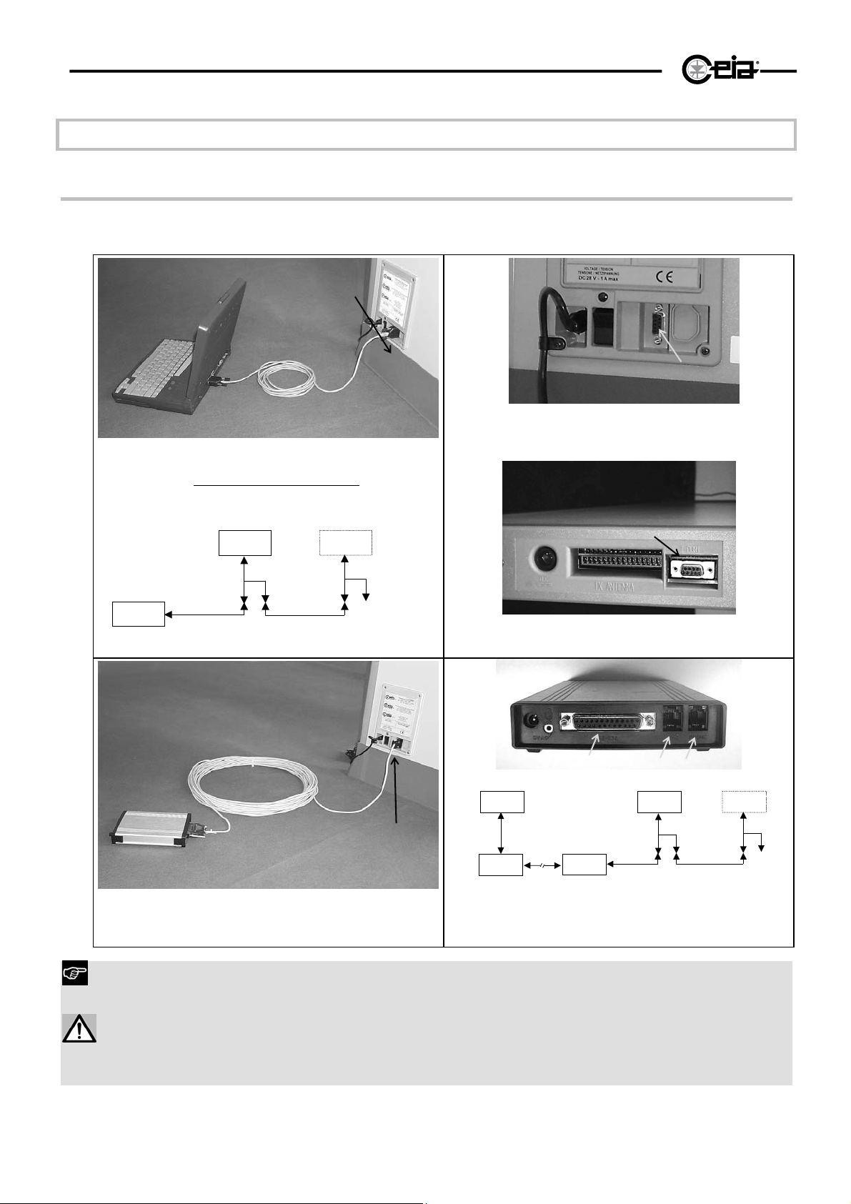
serial line connection to the RS 232 interface. The figure shows how to connect one or more Metal Detectors
to a computer or modem.
MD1
B PORT
B PORT
PC
Fig. IV-4a connection of a metal detector (MD1) to a PC
Note: to connect more than one Metal Detector
special cable is required (code C60363 + C60158). Selection of
each apparatus is carried out by software, using a different
programming password.
MD1
C60363
PC
C60169
Cable C60169
(MD1, MD2), a
MD2
C60363
C60158
Fig. IV-4b
MD1
Cable C60316
T PORT
Fig. IV-5 : Detail of the metal detector connectors
RS 232
Telephone line
MD1PC
MD2
B PORT
MODEM
Fig. IV-6 : Connection of a metal detector (MD1) to a MODEM
The archway is fitted with two connection modules, one module in the lower part of the antenna and another module at the top: make
the connections for serial communication to the module used for the power supply connection. Place the power supply and serial
communication cables together, in order to avoid loops.
If the ALP card is set to enable the functioning of the RCU unit, a +28V supply is connected to pin 1 of the connectors B PORT: in order
to avoid any damage to the PC's interface, make sure that the cable connecting the metal detector to the PC does not include a
connection to pin 1 or, in any case, set the ALP card in the standard operation mode (RCU unit disabled). WARNING! This voltage is
always present at the upper connector T PORT, no matter which position the selector on card ALP has been set to.
Fig. IV-7 - diagram of the connections by linking telephone
C1
TL
MODEM1
line: PC: personal computer; MD1, MD2: metal detectors; c1:
MODEM2
cable for modem; TL telephone line
C60363
C60316
C603463
C60158
Page 31
HI-PE multi-zone --- Rev. FI 050 GB 60K10 v2_1
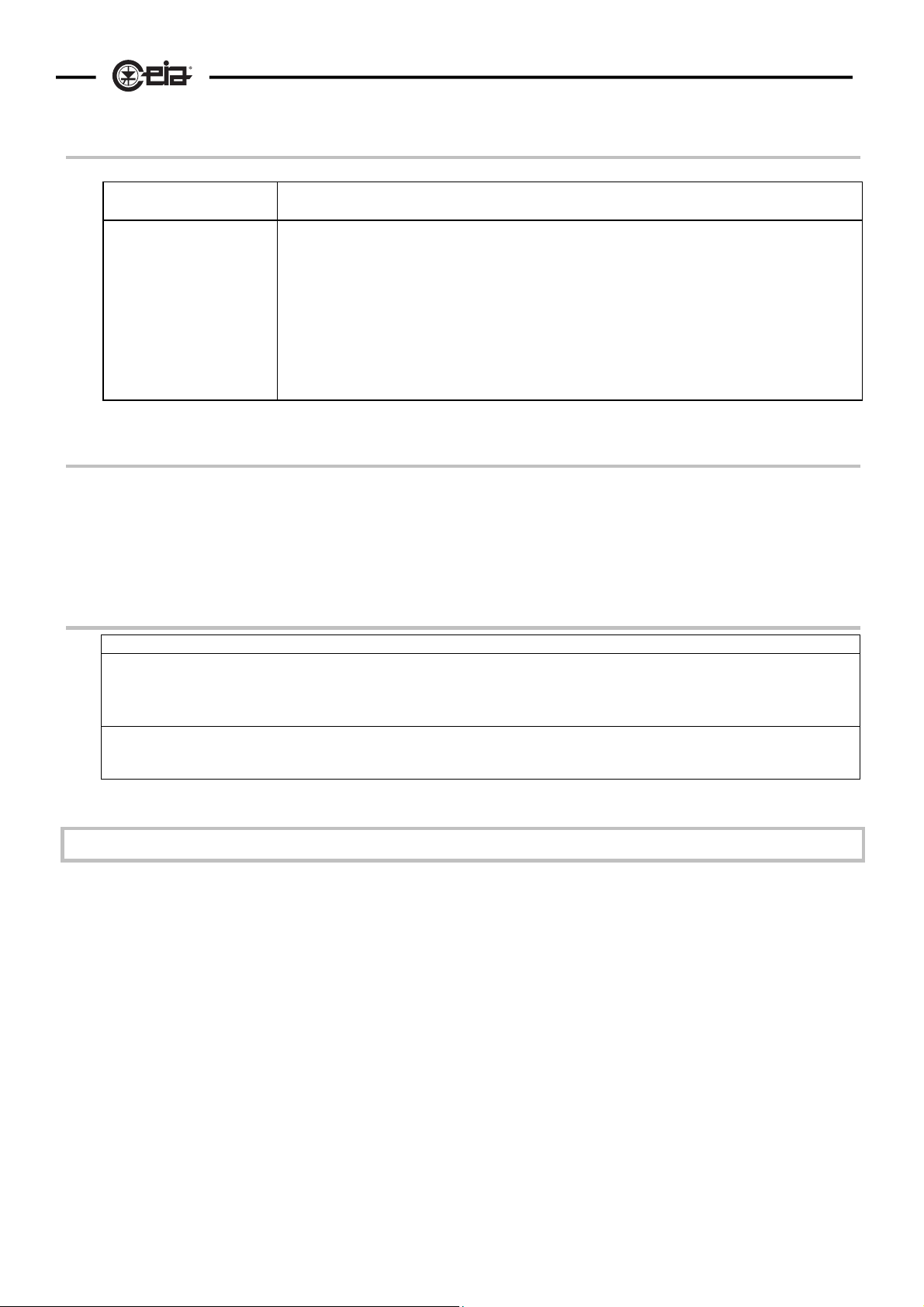
Communication system configuration
Metal Detector Terminal or computer
Select the baud rate on
the Metal Detector
(function BR)
Select the function mode on the computer:
- type: ANSI/BBS, VT100
- baud rate
- 8 data bits
- 1 stop bit
- no transmission protocol
- automatic line feed
- tabulation every 8 characters
- full duplex (fdx)
Free access to programming phase (without password)
Press ENTER to access the programming phase. The prompt " > " will appear on the terminal.
E.g.:
ENTER
> programming phase
31
Execution of commands in remote programming
Everything entered via the terminal keyboard will be displayed on the monitor.
The delete key (BACKSPACE) can be used to correct any possible input errors.
The command will be executed once the carriage return key has been pressed (ENTER)
The syntax for the commands is strict. If any non-valid syntax is entered, an error message will be sent by
the Metal Detector. Either upper or lower case characters can be used to enter commands.
At the end of the programming session, enter the PE (Programming End) command.
: PE ENTER
E.g.
Simultaneous access request by remote and local programming
Local and remote programming sessions can never be open at the same time.
If you press the PROG key on the electronics unit keypad when a remote programming session is in
progress, the following message will appear on the Metal Detector display: BUSY
This message will disappear when any key is pressed. Should the remote programming session be
terminated while the "BUSY" message is still on the display, you will be directly entered into the
programming session.
If you attempt to execute a command in remote mode during a local programming session the message
BUSY will appear and the connection will be automatically interrupted.
Page 32
32
HI-PE multi-zone --- Rev. FI 050 GB 60K10 v2_1
ADVANCED PROGRAMMING: use of the password
Programming levels
Access to the programming phase may be controlled by a password or be unprotected.
There are two programming levels: the user (operator) level and the super-user (supervisor) level.
user level, accessed by entering the "user password":
• The terminal displays the " > " prompt ; in local
programming the display shows "U" on the left.
• The user can define his/her own password using the
NP function. .
• Only some of the functions are available to the user
(these are selected by the super-user using the UP
function)
super-user level, accessed by entering the
"super-user password":
• In remote programming, the terminal displays
the " # " prompt ; in local programming the
display shows "S" on the left
• All the functions are available for the superuser.
• The super-user can define his/her own
password using the NP function.
• The super-user can also decide which
functions are available for the user (see
function UP).
At each programming level, only the password relating to that same level can be modified.
The equipment is usually delivered from CEIA with a password already set for super-user level, while user
level access is unprotected.
We recommend changing the password immediately after installation
and at intervals thereafter, to prevent access to programming by
unauthorized persons.
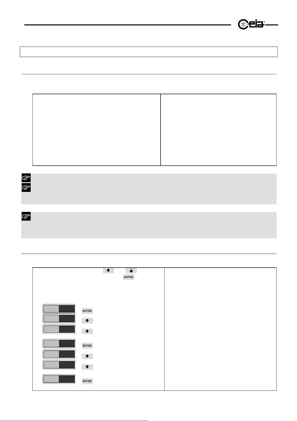
Password definition
The password can be changed by means of the NP command, during a programming phase.
Local Programming: use
select the characters, press the
confirm. The password is made up of 6 letters or
numbers.
E.g.: (example password: ANDREA)
NP
------
000000
:
A00000
A00000
A10000
:
ANDREA
selection of 1st character
confirmation of 1st character
selection of 2nd character
confirmation of 6th character
and keys to
key to
Remote Programming: insert the
password by means of the keyboard.
The password is made up 6 letters or
numbers in upper case or lower case
which are then followed by a carriage
return (ENTER).
Do not use spaces or other
punctuation characters.
E.g.: (example password: ANDREA)
NP=ANDREA ENTER
Page 33
HI-PE multi-zone --- Rev. FI 050 GB 60K10 v2_1
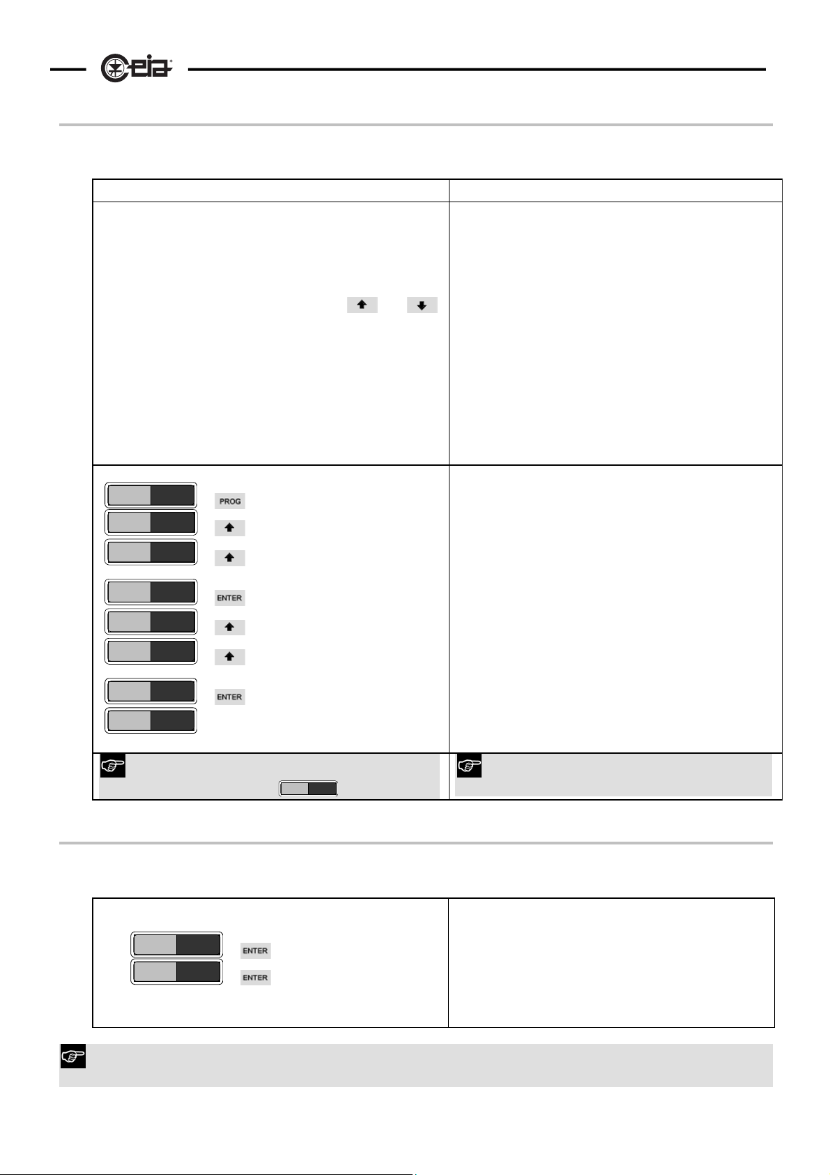
Access to the programming phase using the password
Starting from normal operation, enter the password using the built-in keypad (local programming) or the
terminal keyboard (remote programming).
Local Programming Remote Programming
a) The password is made up of 6 letters or numbers.
b) Press PROG key: 6 dashes will appear on the display:
------
The first dash flashes to indicate the position of the
cursor.
c) Insert the password by activating the
keys to select the characters and then pressing the
ENTER key to confirm.
d) After entering the last character, the programming
phase starts. If the password is not recognised, the
password must be re-entered (go to point b).
e) At the end of the session, press PROG .
and
E.g.: correct operation (password: ANDREA):
- - - -
------
000000
:
A00000
A00000
A10000
:
ANDREA
U SE =34
selection of 1st character
confirmation of 1st character
selection of 2nd character
confirmation of 6th character
programming phase (user level)
a) After powering up the terminal and Metal Detector
(wait the end of the initial warming up period),
enter the password by means of the keyboard.
b) If the password is recognised, the programming
phase prompt will appear (> for user level, # for
super-user level). Otherwise the password must
be re-entered.
After the third failed attempt to enter the
password, the device will pause for 10 seconds to
avoid any computerised search for the password
by ill-intentioned persons.
c) At the end of the session, enter the PE
command (Programming End, see below).
E.g.: correct operation, user level:
. . . . . . ENTER
entering of the password
> programming phase (user level)
33
If a mistake is made, the display returns to the
normal operation sign
- - - -
.
If a mistake is made, the prompt does not
appear
Programming without password
To avoid having to use a password, the code "------" must be assigned to the password. This can be done at
both user and super-user level using the NP function.
Local programming
NP
- - - - - -
ATTENTION! If both levels (user and super-user) have free access, any subsequent programming request
is at super-user level.
Remote programming
Enter the "------" password via the
keyboard
NP=------ ENTER
Page 34
34
e
HI-PE multi-zone --- Rev. FI 050 GB 60K10 v2_1
Parameters accessible from remote programming only
Function code :
C= command
R= status request
S= the command can only be accessed from the super-user level
Code Meaning
Number of
CI
CO
inward
transits
number of
outward
transits
Alarm reset - C
RE
Alarm reset
RM
AA
mode
Indication of
the size of
the metal
mass
detected
HELP - R This selects a display of the meaning of the programming codes. The read-out will give the
HE
Programmin
PE
PT
SC
g end
Parameter
table
Selfdiagnosis
Possible valu
0-999999 R This function displays the number of transits made through the gate, in the direction defined
0-999999 R This function displays the number of transits made through the gate, in the direction opposite
M, A C/R
0-4 R
- C This command will be executed automatically if no commands are entered for a period of 2
- R Displays the values of the operating parameters. The serial number of the device appears at
R Displays the status of the Metal Detector. When operating properly, this message appears:
Type Notes
by parameter GD, since the last time the alarm counter was reset (command CR).
During normal operation, the current value of this parameter can be seen on the display if the
. or key is pressed
to that defined by parameter GD, since the last time the alarm counter was reset (command
CR).
During normal operation, the current value of this parameter can be seen on the display if the
. or key is pressed
ATTENTION! The metal detector will operate under manual reset only during a programming
session and with the reset mode set on "manual" (see the RM function). Outside of the
programming session, the device will operate under automatic reset.
If the RE command has not been authorised for the user environment, the mechanism will
operate under automatic reset during a programming session at user level.
M Mode: corresponds to manual reset via command RE. The alarm is kept in memory until
the RE command is executed. (N.B.: any reset button that might be connected to terminal
PP1 will not have any effect)
A Mode: corresponds to automatic reset:: the alarm stops shortly after the transit through the
transducer is completed.
Displays the size of the metal mass detected (during an alarm in manual reset mode, see RM
function). 5 different values can be adjusted, ranging from:
• 0 (no alarm)
• 1 (small mass)
•
•
• 4 (large mass).
Status reading does not reset the Metal Detector alarm.
correspondence table (function – function code)
The * character indicates that the command is enabled at user level (see the UP
command).
minutes.
the top.
The character * indicates that the command is enabled at user level (see command UP).
OK System working perfectly
If one of the device’s components is faulty, a message will be displayed (in descending order
of priority). For more details see the “Maintenance” section.
N.B.: The SC command can only be executed in remote programming. The self-diagnosis
device is permanently active, and any indication of malfunction is given automatically on the
display.
Page 35
HI-PE multi-zone --- Rev. FI 050 GB 60K10 v2_1
35
V - Technical characteristics
Walk-through gate
Designed and constructed according to the most advanced
technological criteria, the gates are extremely robust and stable, yet
elegant and fully protected against the effects of weather and wearand-tear.
Central electronics unit
• Degree of protection: IP 20 (IEC 529), with standard casing;
IP65 with waterproof casing in stainless steel
• Dimensions and weight: IP 20: 380 x 157 x 82mm; 1,3 kg. ;
IP65: 387 x 178 x 80mm; 2 kg
Inputs/Outputs:
• Power supply: 115/230V~ +10/-15%,, 50 ÷ 60 Hz, 40 VA
• Alarm: NC-NO-C switch alarm relay, NC-NA-C, 1A-24V~
/24Vcc.
• Input for manual resetting of alarm (N.C. contact) or for
connecting photocells to count number of transits.
• Serial interface: RS-232C type with low impedance for
connection to terminal, computer or external modem at a
distance of up to 100 m.
Environmental conditions
• Temperature:
Protection degree
IP20 -10 …+65°C (14…149°F) -35…+70°C (-31…158°F)
• Relative humidity: 0 – 95%, without condensation.
Alarm modes
Signalling
• Detection of masses in transit (automatic or manual resetting)
• Sabotage or internal self-diagnosis
Type of signalling
• Visual: fixed or proportionate to the mass in transit - visible from
• Visual with zonal subdivisions via a vertical LED display on
• Audio: fixed 90 dB(A) at 1m
• By means of relay
PROGRAMMING
Presets
SE 100 sensitivity levels
DS 10 maximum detection speed settings
LS 10 minimum detection speed settings
LC 2 independent sensitivity areas
NL 10 electrical impulse interference limitation levels
CH 100 transmission frequencies
AV 10 levels of alarm volume
AT 10 levels of alarm tone
AD 10 levels of alarm duration
BR 8 serial transmission speeds
NP 2 programming passwords
LD/ST 10 storable programming sets
AU 1 autoset function
GD 2 gate direction
Readout parameters
AA Alarm intensity indicator
AC Alarm counter (transits, alarms and percentage of alarms on
IP55 -20 …+70°C (-4…158°F) -35…+70°C (-31…158°F)
6m under lighting of 4000lux.
the antenna. Resolution: 20 distinct alarm lights. Signalling via a
single floating group of LEDs, or via 4 or 8 individual zones
each of fixed height and position
photocell models)
Working temperature Storage temperature
..
CI Number of inward transits
CO number of outward transits
GN Measurement of general environmental noise
EN Measurement of environmental electromagnetic noise
HE On-line help
PT Table of operating parameters
PV Program version in use
WT Total operating time of the metal detector
Automatic functions
IS Direct selection of International Security Standards
SPECIAL FEATURES
Technology
• Professional high-integration, optimum-reliability electronics
• D.S.P. analysis with numeric filter of the signal received
(patented).
• High immunity demodulation of the signals (patented).
Signalling
• Indication via a vertical LED display on the antenna of
the position of one or more metallic masses passing
through the archway.
• Immediately-available display of security level and number of
transits made in both directions.
Programmability
• Programmability of all the parameters protected by
passwords.
Transit flow
• Very reduced reset time for a rapid flow-rate (detection
speed: up to 15m/sec.)
Multiple installations
• Automatic synchronisation between 2 or more metal
detectors with a reciprocal distance of down to 5 cm without
the use of cables.
Remote control
• Capacity for total remote control through an RS-232C serial
line.
Installation and maintenance
• Automatic adjustment to environmental parameters and
absence of initial or periodic calibrations.
• Proper environmental installation checked by means of a
read-out of the general noise “GN” and electromagnetic
noise “EN”.
• Autoset function to reset the default operating parameters
Metal Detector Utilities
• A complete range of accessories for calibration and
advanced management of CEIA Metal Detectors.
Certifications and conformity
Harmlessness
• Certified as harmless to wearers of pacemakers, invalids,
pregnant women and so forth.
• Harmless to magnetic media (floppy disks, tapes, etc...).
Standards
• Conforms to the NILECJ-0601 standards for all security
levels and to the FAA “3-Gun Test” standard.
• Conforms to the international standards currently applicable
for electrical safety and EMC, and to the applicable EC
Regulations.
• Approved Ministries and Authorised public bodies.
• Complies with Scandinavian CAA specifications.
Page 36
36
HI-PE multi-zone --- Rev. FI 050 GB 60K10 v2_1
VI - MAINTENANCE
Before working with the device read the warnings and instructions in this section and in the paragraph
“Installation, use and safety information” carefully. Please note that CEIA is not responsible for any
damage that may result from installations that do not follow these guidelines.
Suggested Maintenance Schedule
Execution
Operation
Battery
replacement
Autotest
General cleaning
Visual check that
all components of
the metal
detector are
undamaged.
Visual inspection
of connectors
and power
supply cables.
Floor anchoring
inspection:
ensure that the
archway is firmly
anchored to the
floor. *
Cross-bars
inspection:
ensure that the
cross-bar screws
are properly
tightened.
Control unit
inspection:
ensure that the
fixing screws are
properly
tightened.
Verification of the
calibration
* Advance notice must be given to the Security Manager regarding any movement of the Metal Detector
to a position different from that of the original installation. The operation itself must be performed by
technicians trained in the installation and validation of calibration procedures
Tools
required
Medium size
Phillips
screwdriver
(PH1)
- -
A slightly
moist, non-
abrasive cloth
- -
- -
- -
Supplied
Allen Key N°8
Supplied
Allen Key N°5
Test piece
specified by
the Security
Standard in
use
Items
required
2 batteries
-
-
-
Operator
Technician
Maintenance
Recommended: 3 years
•
•
•
•
•
•
•
•
•
Replacement Inspection
(maximum: 5 years)
- 12 months
- 4 months
- 4 months
- 4 months
- 4 months
- 4 months
- 4 months
-
Period
-
• Daily
• At shift changes
• In case of doubt of
proper operation
Page 37
HI-PE multi-zone --- Rev. FI 050 GB 60K10 v2_1
Diagnosis
Message Possible cause Recommended action
RX ERR
GATE
PROG
RS232
BUSY
WAIT
RESTART
fault in the receiving section
connecting cable damaged or
disconnected
damaged transducer
loading of data via the LD or IS commands
from an unprogrammed memory cell
serial interface malfunction
attempt to access programming in local
mode while a session is already underway
in remote mode, or vice-versa.
Metal detector not operative • Temporary adjustment phase following to the
Metal detector not operative
• Check the choice of transmission channel
(function CH) if more than one metal detector is
installed (see related para. in “Installation”
section)
• replace the electronics unit
• check the connections between electronics unit
and antennae
• check that no nails or screws have been driven
into the transducers without prior consultation
with the technical department of CEIA.
• replace the connecting cable
• replace the transducer
• Programme the memory cell (ST command) or
use a pre-programmed memory cell.
• check the serial line connections
• check that serial transmission mode has been
selected correctly at both the detector and the
remote terminal (see Programming section)
• replace the electronics unit
• Exit from programming phase
modification of either the receiving or the
transmitting parameters (e.g.: channel "CH"): wait
for normal functioning indication.
• Temporary adjustment phase following to the exit
from the EN function.
37
Page 38
38
HI-PE multi-zone --- Rev. FI 050 GB 60K10 v2_1
Troubleshooting
Before analysing possible faults, please check:
• that the connectors are properly connected
• that the operating parameters have the correct values (see the test ch eck-sheet included at th e end of
the manual).
There follow some indications regarding possible causes of malfunction and check procedures to be carried
out in order to restore the metal detector to its correct operational status.
Fault Possible cause Recommended action
Display off
Malfunction of ALP card
Power comes
on and goes
off in
succession
Model with
photocells:
no passage
detection
The Metal
Detector does
not give any
alarm when a
metal object
is in transit,
even if
sensitivity is
at its highest
setting.
PW = OFF
Electronics unit fault
Fault in the supply section
Model with emergency
batteries. Flat batteries
Power supply voltage
unstable or too low
malfunction of the
photocells
Malfunction of power
supply section
Malfunction of transmitting
section
Incorrect programming · Check that the programming procedure works properly: if not, replace the
If the Metal Detector still does not operate properly, please contact our Technical Department for advice.
Set PW = ON
• check all the power connections (mains cable, electronics unit - TX antenna
connecting cable, connector J2 on electronics unit)
• If the power supply voltage is present at the electronics unit (Autotest
procedure or instrument check on connector J2, contacts +/~ and -/GND),
replace the electronics unit
• If the power supply voltage appears at connector J2 only when it is
disconnected from the electronics unit, replace the electronics unit.
• check all the power connections (mains cable, electronics unit - TX antenna
connecting cable, connector J2 on electronics unit) .
• Check that the LED on the ALP card is on.
• If the LED is off, replace the external PSA power adapter.
• If the LED is on, replace the ALP card.
Connect the equipment to the mains supply and recharge the batteries.
• Check the battery voltages. Replace damaged batteries.
• If batteries are flat, check the recharging section:
• activate the on/off switch an check that the light on the card is on with
batteries connected and off with batteries disconnected.
• replace card ALP
· Check the power supply voltage with instruments or by carrying out the
Autotest procedure.
· Wrong programming of GD function: refer to paragraph Autoset program
· Dirty or defective photocell: check with the Autotest procedure. If
necessary, replace it.
Check the power supply voltage by carrying out the Autotest procedure.
check transducer-electronics unit connections
electronics unit.
· Buzzer off: set AV>0
Page 39
HI-PE multi-zone --- Rev. FI 050 GB 60K10 v2_1
39
Compatibility aspects
Failure Check and action
The Metal Detector
gives irregular
alarms with no
people or objects
passing through it
and without
neighbouring
mechanical
structures being
shaken
High environmental
interference (display
indication
or higher)
The Metal Detector
gives irregular
alarms when the
neighbouring
mechanical
structures move
slightly or vibrate
High environmental
interference (display
indication
or higher)
**
**
If the source of the interference is still not clear, please contact our Technical Department and we will give
Check electrical interference using the EN function
If EN>3:
eliminate the source of interference
move the source of interference away from the metal detector, especially from the receiver
antenna RX; in particular, check that:
there are no electric power lines running near the sensitive probe.
The probe-electronics unit connecting cable runs in its own duct, and not together with power
supply cables to motors, relays or various slave devices.
screen the source of interference using an iron container.
if the source of interference can not be eliminated, move the metal detector, especially the
receiver antenna RX, away from it.
change the transmission channel (CH function) and select the value that corresponds to the
minimum amount of electrical noise. In the case of multiple installation, select different
if the mechanical interference signal is strong (EN =0 but GN>0) without the neighbouring
If EN >3, the interference is of an electrical nature; see the preceding point.
If EN ≤3, the interference is of a mechanical nature:
transmission channels on the individual detectors (see section “Installation of coupled metal
detectors: synchronisation”).
set the noise limiter NL to 9 (not possible in the preceding situation)
decrease DS value (verify the compliance to the selected Security level ! ).
structure being shaken, replace the electronics unit.
Make sure the probe is anchored securely. Avoid vibration or any other movement of the metal
detector.
make sure that no nails or screws have been driven into the transducers
move the metal detector away from the source
eliminate the source of interference :
if the source consists of movement of large metal masses in the vicinity of the probe:
avoid movement of the metal masses, or move them away from the probe;
if this is impossible, replace them with parts made of insulating material (glass, wood,
plastic …)
if the source consists of modifications of the mechanical structure which are shaken
during operation and create intermittent loops which cause strong variations in the magnetic
field:
identify and eliminate these metal structures, or, where this is not possible, insulate them.
in the case of installation near big metallic structures (distance less than 0.5 m), check
that when these latter are physically shaken (e.g. by knocking them) they do not cause
interference in the metal detector.
(*) If the signal received by the metal detector has a high variation (GN
event if the display shows more than one asterisk in its green sector
increase the stability of the system
Access system with two interlocked metal doors If the signal does not change
noticeably when vibrations occur, try opening and closing the entry doors: if the
interference is linked to this kind of movement, the signal will vary. Two possibilities
can be noted:
The variation is slow and follows the door movement:
in general:
interference
door made of metal sections:
metal parts which pass close to the metal detector during movement of the door
replace with corresponding parts made of insulating material
deformation of the supporting structure
weight of the door
The variation is fast and sudden, and occurs especially when the door slams. In
this case the variation is not due to the door but to intermittent points of contact in
the structure. See point (*) for the steps to take.
move the Metal detector further away from the door which causes the
break the loop formed by the sections
: strengthen the structure or reduce the
≥ 8 or in any
**
you all the information you need
),
:
Page 40
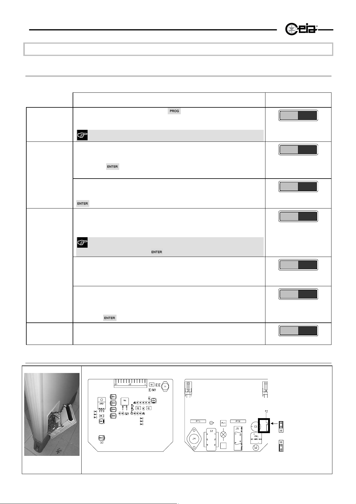
40
HI-PE multi-zone --- Rev. FI 050 GB 60K10 v2_1
Procedures
Autotest program
When the detector is switched on, a program may be run to test some of its components.
Operations to carry out
Activating the
Test display
Photocell test
(if photocells
are installed)
Turn on the detector and keep the key of the central electronics
test
unit pressed down until the signal shown on the right appears .
the program can also activated by means of the PW command.
First phase
Checks correct functioning of all the segments of the display, which
should give the signal shown on the right.
Press the
second phase.
Second phase
Checks the correct functioning of all the segments of the display,
which should now give the signal shown on the right. Press the
key of the electronics unit.
The display of the electronics unit shows the signal: PI- PO- (see
right) without any object or person passing through the passageway:
the photocells do not "see" anything.
key on the electronics unit keypad to go on to the
Display
0*0*0*0
0*0*0*0
*0*0*0*
PI - PO-
*
*
0
If the test is being carried out on a metal detector that is not fitted
with photocells, press to pass to the next phase.
Cover the first photocell relative to the direction of passage (see the
GD function, Programming section). The display should indicate the
passage of an object through the entrance photocell (PI*).
Cover the second photocell relative to the direction of passage.
The display should indicate the passage of an object through the exit
photocell (PO*).
Voltage
Press the
The electronics unit display shows the DC voltage of the electronics
unit, updating the data continuously (in the example to the right,
31.8Vdc). The correct voltage levels are between 22 and 35 Vdc.
key of the electronics unit.
ALP card: trouble-shooting diagram
PI * PO-
PI - PO
VIN=31.8
J1,J3 battery connector
on/off indicator
L1
S1 on/off switch
J6 RCU unit power
supply selector:
*
Fig VI-1 ALP card (with battery charger
RCU activated
RCU deactivated
Page 41
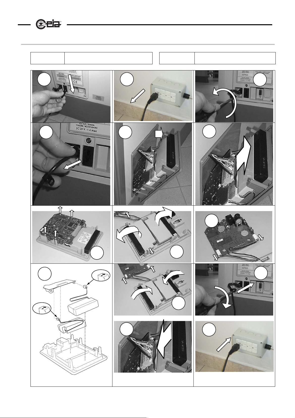
HI-PE multi-zone --- Rev. FI 050 GB 60K10 v2_1
Battery replacement procedure
Necessary
tools
Medium size Phillips screwdriver PH1 Necessary
items
41
CEIA Spare batteries (2 pieces)
1
4 5
2
3
6
9
10
Fig VI-2
7
8
11
12
13
14
Page 42
42
HI-PE multi-zone --- Rev. FI 050 GB 60K10 v2_1
VII - Appendices
DECLARATION OF CE CONFORMITY
DECLARATION OF CONFORMITY CE
DECLARATION DE CONFORMITE CE KONFORMITÄTSERKLÄRUNG CE
DECLARACION DE CONFORMIDAD CE DICHIARAZIONE DI CONFORMITÁ CE
Manufacturer
Fabricant / Hersteller / Fabricante / Costruttore:
Declares that the product
déclare que ce produit / erklärt, daß das Produkt / declara que el producto / dichiara che il prodotto:
Product name:
Nom du produit: / Produktname:
Nombre del producto: / Nome:
Série / Serie / Serie / Modello:
Safety / Sécurité / Sicherheit / Seguridad / Sicurezza:
Safety requirements for electrical equipment for measurement,
control, and laboratory use -- Part 1: General requirements
Safety of power transformers, power supply units and similar --
Part 1: General requirements and tests
Limitation of human exposure to electromagnetic fields from
devices operating in the frequency range 0 Hz to 10 GHz, used
in Electronic Article Surveillance (EAS), Radio Frequency
Identification (RFID) and similar applications
This product complies with the requirements of the Low
Voltage Directive 73/23/EEC and following modifications
indicated in the 93/68/EEC Directive.
Le produit ci-dessus répond aux exigences de la Directive
73/23/CEE et aux modifications suivantes mentionnées dans
la Directive 93/68/CEE concernant la basse tensions.
Dieses Produkt entspricht den Anforderungen an
Niederspannungsgeräte gemäß der Norm 73/23/EEC und
nachfolgender, in der Norm 93/68/EEC angegebener
Änderungen.
El producto indicado cumple los requisitos de la Low Voltage
Directive 73/23/CEE y siguientes modificaciones indicadas en
la Directiva 93/68/EEC.
Il prodotto è conforme alle norme della direttiva 73/23/EEC e
successive modifiche indicate nella direttiva 93/68/EEC sulla
bassa tensione.
Model
est conforme aux spécifications suivantes / folgenden Produktspezifikationen entspricht
es conforme a las siguientes especificaciones / è conforme alle seguenti specifiche di prodotto:
EN 61010 - 1 (2001)
EN 61558 - 1 (1998)
EN 50364 (2001)
HI-PE Multi-Zone
conforms to the following Product Specifications
CEIA S.p.A.
Zona industriale Viciomaggio 54/G 52040
Viciomaggio - Arezzo - ITALY
Walk-Through Metal Detector
Détecteur de Métaux / Elektronischer Metalldetektor
Detectores de metalesl / Metal Detector Elettronico
all models
tous modèles/ alle Modelle
EMC
Electromagnetic compatibility (EMC) -- Part 6-1: Generic
standards - Immunity for residential, commercial and lightindustrial environments
Electromagnetic compatibility (EMC) -- Part 6-3: Generic
standards - Emission standard for residential, commercial and
light-industrial environments
This product complies with the requirements of the EMC
Directive 89/336/EEC and following modifications indicated
in the 91/263/EEC, 92/31/EEC, 93/68/EEC and 93/97/EEC
Directives.
Le produit ci-dessus répond aux exigences de la Directive
89/336/CEE et aux modifications suivantes mentionnées dans
les Directives 91/263/EEC, 92/31/EEC, 93/68/CEE et
93/97/EEC concernant les interférences électromagnétiques.
Dieses Produkt entspricht den Anforderungen der EMC-Norm
89/336/EEC und nachfolgender in den Normen 91/263/EEC
92/31/EEC, 93/68/EEC und 93/97/EEC angegebener
Änderungen.
El producto indicado cumple los requisitos de la Directiva EMC
89/336/CEE y siguientes modificaciones indicadas en las
Directivas 91/263/EEC, 92/31/EEC 93/68/EEC y 93/97/EEC.
Il prodotto è conforme alle norme della direttiva EMC
89/336/EEC e successive modifiche indicate nelle direttive
91/263/CEE, 92/31/EEC, 93/68/EEC e 93/97/CEE.
todos los modelos/ tutti i modelli
EN 61000-6-1 (2001)
EN 61000-6-3 (2001)
Arezzo, 2005 - 01 - 31
Person in charge Lab. EMC
Resp. Laboratoire EMC / Laborattaché EMC
Resp. Laboratorio EMC / Resp. Lab. EMC
Ing. E. Sorini
SpA
Page 43
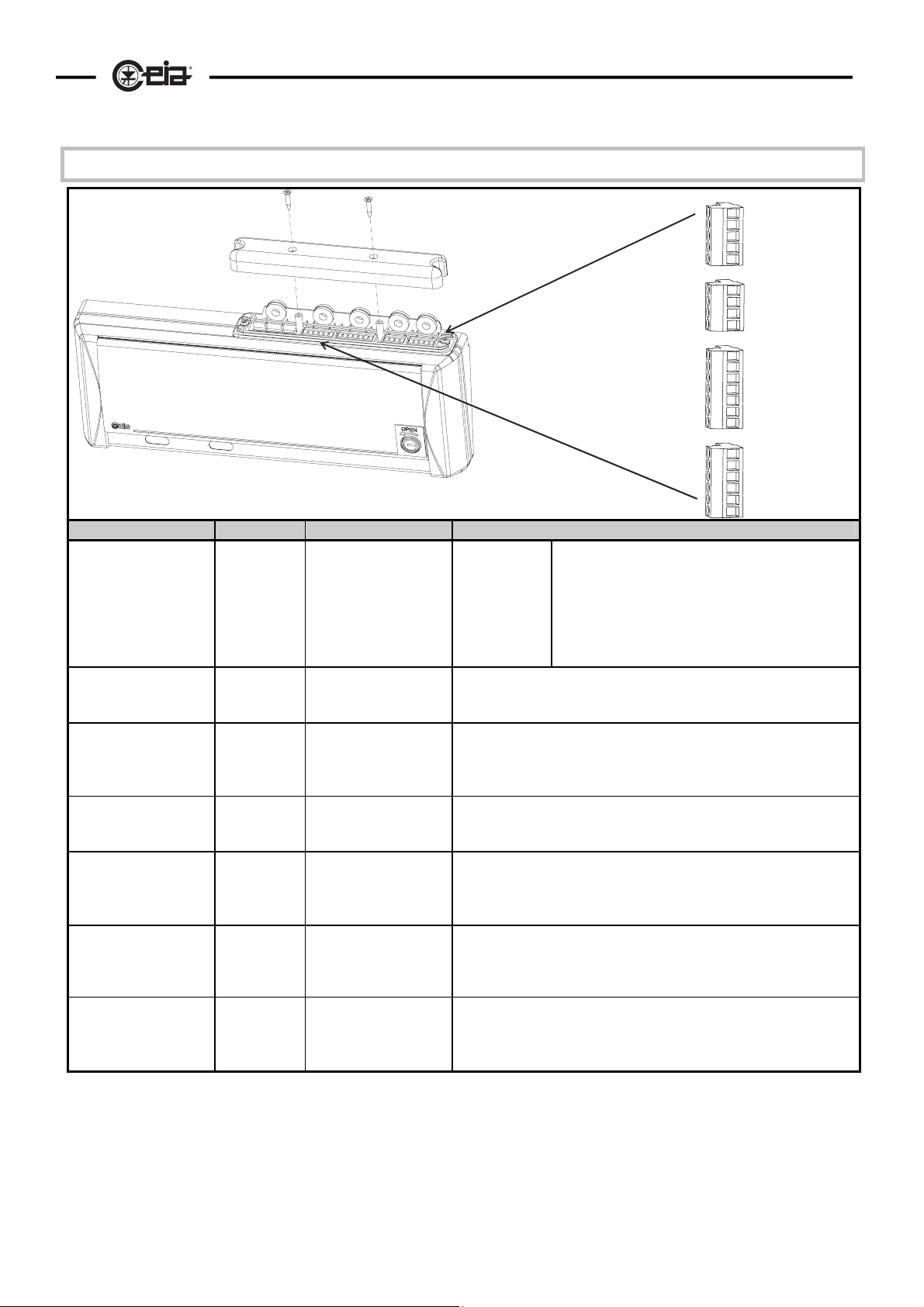
HI-PE multi-zone --- Rev. FI 050 GB 60K10 v2_1
Electrical connections
Fig. VII-1
Function Connector Pins Description
Serial communication
Photocells - monitoring
of the transits through
the gate (optional)
Manual reset – alarm
memorisation
Indicator bar driver
Relay
Power supply
Antenna connection
J1 6 - SER GND
3 - BUSY
2 - SER OUT
1 - SER IN
J1 6 - SER GND (ground)
5 - PP1
J1 6 - SER GND (ground)
5 - PP1
J1 6 - SER GND (ground)
4 - INIB
J2 11 - C (common)
12 - NA (norm. open)
13 - NC (norm. closed)
J2
10 GND
9 GND/-B
8 ˜
7 +B/˜
J4 - J3 A B C H K
F D E Y
ground
busy line
data output
data input
Contacts PP1-SER.GND on the J1 terminal board are connected to
two photocells p1, p2 (located on the antenna) .
N.B. manual reset is not available
Connect a normally closed push-button: when an alarm occurs this
button keeps the output relay in alarm condition until it is
pressed
Reserved
A switch contact NC-C-NA, where position NC coincides with the
normally closed contact and position NA with the normally open one
(closed when there is an alarm)..
Reserved
Reserved
43
A
B
C
H
K
F
D
E
Y
13 NC
12 NA
11 C
10 GND
9 GND/-B
8 ˜
7 +B/˜
6 SER.GND
5 PP1
4 INIB
3 BUSY
2 SER OUT
1 SER IN
J4
J3
J2
J1
The BUSY line is used to monitor the
communication network between several Metal
Detectors; it is normally at "high" level (+5V); when
a Metal Detector effects a data transfer, the line
goes down to "low" level ( 0V ) and indicates to the
other devices that the network is busy.*
Page 44
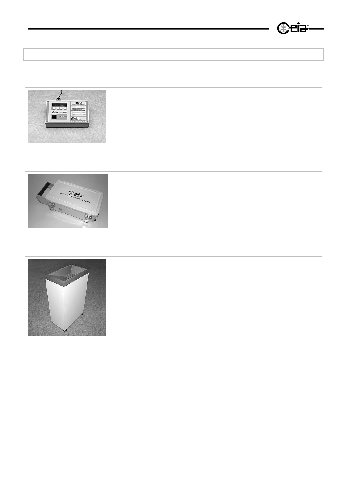
44
HI-PE multi-zone --- Rev. FI 050 GB 60K10 v2_1
ACCESSORIES
RCU
The RCU, connected to the detector via serial line, allows remote programming. It
also provides audible and light-based alarm signalling with a bar-graph indication
proportional to the metal mass detected.
Dimensions: 217x140x75 mm.
Code: 3423
Fig. VII-2
MAIN & BATTERY SUPPLY UNIT
The MAIN & BATTERY SUPPLY UNIT is a portable device for providing power to
CEIA metal detectors in outdoor applications or in particularly difficult
environmental conditions.
The unit comprises two 12V, 7Ah batteries and a charger, and allows about 6
hours independent operation when mains power is not available. Recharging
takes place automatically when mains voltage is present.
Protection level: IP65.
Fig. VII-3
Code: MBSU-1
Personal Effects Depository
This article acts both as a spacer between the X-ray unit and the metal detector
and as a temporary depository for metal personal effects which are not of dubious
nature and therefore not required to undergo X-ray analysis (coins, keys and so
on).
Dimensions: 610 x 360 x 975 mm
Code: 18074
Fig. VII-4
Page 45
HI-PE multi-zone --- Rev. FI 050 GB 60K10 v2_1
SPARE PARTS
All of spare part orders should bear the serial number of the equipment!
HIPE/PTZ
Validity: revision 8
Spare parts
Description
IP20 electronics unit
RX antenna - Code S100
RX antenna - Code S100/S
TX antenna - Code S100
Electronic cards of the antenna luminous bar
Installation kit
Front cover with lock
Keys of the keypad (4)
Options
Description
Cables connecting the antenna to the electronics unit - 720mm cross-bar
Cable connecting the antenna to the electronics unit - 820mm cross-bar
720mm cross-bar with holes
720mm cross-bar without holes
760mm cross-bar with holes
760mm cross-bar without holes
820mm cross-bar with holes
820mm cross-bar without holes
230Vac Power supply adaptor for Europe
115Vac Power supply adaptor for USA
100Vac Power supply adaptor for Japan
Photocell assembly ( 1 card + 1 cover)
Power supply module with battery-charger
12V-0.8Ah battery
Power supply module without battery-charger
Quantity Code
1 24848
1 24342
1 36730
1 32809
1 21146
1 24258
1 24873
1 29415
Quantity Code
1 25034
1 25035
1 24255
1 24256
1 24253
1 24254
1 24251
1 24252
1 19360
1 19361
1 36481
1 32716
1 24343
1 19
1 24344
45
Page 46
46
HI-PE multi-zone --- Rev. FI 050 GB 60K10 v2_1
HIPE/PTZ-WP
Validity: revision 3
Spare parts
Description Quantity Code
IP65 electronics unit 1 23841
Keys of the keypad (4+4) 1 29415
RX antenna S100 1 23821
TX antenna S100 1 23820
Cables connecting the antenna to the electronics unit - 760mm cross-
1 23843
bar
760mm cross-bar with holes 1 23470
760mm cross-bar without holes 1 23471
Electronic card of the antenna luminous bar 1 21146
Photocell assembly 1 32824
Upper protection 1 23701
Threaded knob for the upper protection 4 24966
Installation kit 1 24259
Power supply module with battery-charger 1 23835
12V-0.8Ah battery 1 19
External protection 1 23670
Options
Description Quantity Code
230Vac Power supply adaptor for Europe
115Vac Power supply adaptor for USA
100Vac Power supply adaptor for Japan
1 19360
1 19361
1 36481
Page 47

HI-PE multi-zone --- Rev. FI 050 GB 60K10 v2_1
47
Page intentionally left blank
Page 48

48
HI-PE multi-zone --- Rev. FI 050 GB 60K10 v2_1
www.ceia.net
 Loading...