

Installation manual plugs and connectors with screw connection
(63/125 A)
Issue 04.2016
2016-04-01
EN
60003215
Installation manual plugs and connectors with screw connection (63/125
Table of contents
1 About this manual 3
1.1
Structure of the warnings 3
1.2
Symbols used 4
1.3
Signal words used 4
Intended use 5
2
General safety instructions 6
3
Packaging, transport and storage 7
4
4.1
Packaging 7
4.2
Transport 7
4.3
Storage 7
Design 8
5
Assembly and disassembly 9
6
6.1
Connecting a cable to a 63-A / 125-A plug or socket 9
6.2
Disconnecting a cable from a 63-A / 125-A plug or socket 11
Cleaning and care 13
7
A)
Decommissioning and disposal 14
8
(04.2016)
2 / 16
Installation manual plugs and connectors with screw connection (63/125
A)
About this manual
1
This manual
– describes the assembly and disassembly of plugs and sockets with screw connections of Bals El-
ektrotechnik GmbH & Co. KG
– is an integral part of the product and must be kept in safe custody during the product service life
– must be read carefully and understood before use and any work.
Structure of the warnings
1.1
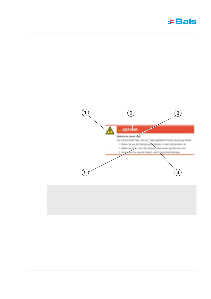
The following picture illustrates the structure of a sample warning.
1 Hazard-specific symbol
2 Signal word
3 Type and source of the hazard
4 Possi ble consequences of failing to comply
5 Procedure for avoiding hazards
(04.2016)
3 / 16

Installation manual plugs and connectors with screw connection (63/125
Symbols used
1.2
General warning of a hazardous area
Warning – dangerously high voltage
Notice
Signal words used
1.3
All warnings in this manual are clearly highlighted. The following signal words are used for warnings:
A)
(04.2016)
4 / 16
DANGER Warns of dangers which will lead to serious injuries or to death if the instructions are not fol-
lowed.
WARNING Warns of dangers that may lead to serious injuries or to death and/or cause considerable dam-
age to property if the instructions are not followed.
CAUTION Warns of dangers that may lead to reversible injuries and/or considerable damage to property if
the instructions are not followed.
NOTICE Warns of dangers that may lead to operational disruptions and/or considerable damage to prop-
erty. Damage to the environment, too, may occur if the instructions are not followed.

Installation manual plugs and connectors with screw connection (63/125
A)
Intended use
2
Plugs and sockets with screw connections are built for professional use. The installation and the fixed
connection to the mains supply should be carried out only by trained and qualified experts.
Any use going beyond the intended use is considered to be improper. The manufacturer is not liable
for damages resulting from improper use. Any such risk shall be borne solely by the user.
In case of unauthorised modifications or conversions, the CE conformity becomes null and void, and
thus, also all claims for warranty. Modifications may lead to risks for life and limb as well as damage
to the plugs and sockets or loads connected.
Factory-fitted labels and markings on the plugs and sockets should not be removed, modified or
blurred.
Protect against foreign bodies and impact of weather
The plugs and sockets meet either the protection degree IP44, IP54 or IP67 in accordance with DIN
EN 60529 (VDE 0470-1), depending on the respective design. Each of these mean:
– Protection degree IP44:
– Protected against solid bodies with a diameter beyond 1.0 mm, e.g. a wire
– Protection against water sprayed from all sides
– Protection degree IP54:
– Protected against dust in damaging quantity
– Complete protection against contact
– Protection against water sprayed from all sides
– Protection degree IP67:
– Dust-proof
– Complete protection against contact
– Protection against temporary immersion
(04.2016)
5 / 16

Installation manual plugs and connectors with screw connection (63/125
Environment
The following operating temperatures apply for the safe operation of the product:
Standard version
-25 °C ... +40 °C -33 °C ... +49 °C
General safety instructions
3
– Safe use is ensured only if this manual is followed completely.
– Before installation, commissioning or operation, read this manual thoroughly.
– The plugs and sockets must be installed, maintained and put into operation properly by qualified
experts in accordance with the laws, ordinances and standards.
– Keep easily combustible and explosive materials away from the plugs and sockets.
– Handle the cables with care
– by always pulling at the plug and not the cable when unplugging,
– by preventing the cable from getting damaged mechanically,
– by keeping intense heat away.
– Never use faulty products or products with dirty, scratched or damage contacts.
– Keep the contacts on the product clean.
– Avoid tripping hazards.
Military version
A)
(04.2016)
6 / 16

Installation manual plugs and connectors with screw connection (63/125
A)
Packaging, transport and storage
4
Packaging
4.1
Packaging materials are valuable raw materials and can be reused. The packaging materials should
therefore be brought to an appropriate recycling facility. If this is not possible, dispose of the packaging materials according to the locally applicable regulations.
Transport
4.2
Check the delivery for completeness and integrity. If you identify transit damage or if the delivery is incomplete, notify your dealer or supplier immediately.
Storage
4.3
The product must be stored in clean condition and protected from dust and humidity. The original
packaging is best suited for this purpose.
(04.2016)
7 / 16

Installation manual plugs and connectors with screw connection (63/125
Design
5
Based on an example, the following figure illustrates the main components of the plugs and sockets
with screw connections.
1 Front part with screw terminals for all types of copper conductors
2 Housing
3 Cable gland with multi-grip as integrated strain relief
Conductor cross-sections
The following table displays the possible conductor cross-sections that can be connected to the plugs
and sockets:
A)
(04.2016)
8 / 16
Design Possible conductor cross-section
63 A 6 mm
125 A 16 mm2 ... 50 mm
2
... 16 mm
2
2
Cable diameter
The following table displays the cable diameters that can be used for plugs and sockets with multi-grip:
Design Possible cable diameter
63 A, 3-pin to 5-pin 16 mm ... 36 mm
125 A, 3-pin to 5-pin 26 mm ... 50 mm
Technical specifications
The technical specifications of the plugs and sockets depend on the design. You will find them in our
catalogue or on our website http://www.bals.com.

Installation manual plugs and connectors with screw connection (63/125
A)
Assembly and disassembly
6
DANGER
Danger to life by electrical voltage
The supply cable may carry high electrical voltage that is fatal. Pay attention to the five safety rules of
electricity:
1. De-energise
2. Secure the supply from being switched on again
3. Ensure the de-energised condition
4. Connect to earth and short circuit
5. Cover or cordon off adjacent live parts
Connecting a cable to a 63-A / 125-A plug or socket
6.1
Proceed as follows:
1. Make sure that the cable is de-energised.
2. Open the rotary lock to separate the front part (1) from the housing (2).
3. Push the cable about 50 cm wide through the cable gland and housing.
4. Strip the cable to the required length (63-A designs: 110 mm; 125-A designs: 150 mm).
5. Remove the insulation from the individual conductors (63-A designs: 19 mm; 125-A designs:
25 mm).
6. For better, permanent contact, provide the individual conductors with suitable conductor end
sleeves. You do not need these if the plug or socket is fitted with box terminals.
7. The terminals are open at the time of delivery. Guide the individual conductors into the opening (5) and tighten the screws (4). For doing this, the tightening torque must be 2 Nm for the
63-A designs and 4 Nm for the 125-A designs. Take care to see that only the individual conductor (without insulation) is clamped. Pay attention to the marking of the terminals and ensure that the assignment of the individual conductors to the terminals is correct.
(04.2016)
9 / 16

Installation manual plugs and connectors with screw connection (63/125
8. Connect the housing and front part with screws until the triangular markings (7) lie over one
another.
9. Fix the connection using the white latch (6) fixed on the side. The latch must be pressed in
front until it gets latched audibly.
A)
(04.2016)
10 / 16
10. Next, tighten the cable gland (3). The tightening torque must be between 7.5 Nm and 20 Nm
for the 63-A designs and between 10 Nm and 22 Nm for the 125-A designs. Please refer to
the embossing on the cable gland for the exact value of the respective design. Secure the cable gland using the screw placed on the side for this purpose (8, depending on the design).

Installation manual plugs and connectors with screw connection (63/125
A)
11. Check that the cable is seated tightly in the plug or socket.
Disconnecting a cable from a 63-A / 125-A plug or socket
6.2
1. Make sure that the cable is de-energised.
2. If the cable gland (3) is secured with the help of a screw (8), loosen this screw.
3. Loosen the cable gland.
4. Disconnect the joint between the housing (2) and the front part (1). To do this, pry open the
white latch (6) fixed on the side with a screwdriver.
(04.2016)
11 / 16

Installation manual plugs and connectors with screw connection (63/125
5. Unscrew the housing from the front part.
6. Push the housing and the cable gland back on the cable until the connections in the front part
are easily accessible.
7. Loosen the screws (4) of the terminals and pull out the individual conductors from the terminals.
A)
(04.2016)
12 / 16
8. Pull the cable out of the housing and out of the cable gland.

Installation manual plugs and connectors with screw connection (63/125
A)
Cleaning and care
7
It is recommended to clean the device as required. Use a dry cloth to clean the device. Use a wet cloth
if the device is very dirty.
DANGER
Electrical voltage
The device contains parts that carry hazardous voltage that may be fatal.
1. Pull out the plugs to the loads before cleaning them.
2. Make sure that the plug covers are closed.
3. Never use steam or water jet cleaners.
NOTICE
Damage to the plastic parts.
Corrosive cleaning agents may attack or destroy the plastic parts.
Use only a cloth moistened with water for cleaning.
(04.2016)
13 / 16

Installation manual plugs and connectors with screw connection (63/125
Decommissioning and disposal
8
Send the worn-out product for recycling or for proper disposal. Always make sure to observe and follow the local regulations.
The product should not be disposed of in household waste. Environmental damage and risk to personal health are avoided with proper disposal.
A)
(04.2016)
14 / 16

Notes
(04.2016)
15 / 16

Bals Elektrotechnik GmbH & Co. KG
Burgweg 22
57399 Kirchhundern
GERMANY
Tel.: +49 27 23 / 7 71-0
Fax: +49 27 23 / 7 71-1 77
E-mail: info@bals.com
Disclosure to third parties only with the consent of
Bals Elektrotechnik GmbH & Co. KG. All rights reserved.
Only valid at the time of printing. Update when reused.
 Loading...