

Page 1

Owner’s Manual
X-PRO II Workstation
www.costeffectiveequipment.com
+1-573-466-4300
Page 2

Cee® X-Pro II Workstation Manual
Contents'
1. X-Pro II Workstation Introduction............................................................................................................ 3
1.1. Confidentiality Statement ........................................................................................................................... 3
1.2. Warranty ........................................................................................................................................................ 3
1.3. Returned Materials....................................................................................................................................... 3
1.4. Model and Revisions ................................................................................................................................... 4
1.5. Safety Hazards/Precautions ....................................................................................................................... 4
1.6. Overview of Equipment-Specific Hazards ............................................................................................... 4
1.7. Electrical ........................................................................................................................................................ 4
1.8. Thermal .......................................................................................................................................................... 4
1.9. Mechanical .................................................................................................................................................... 4
1.10. Chemical .................................................................................................................................................... 5
1.11. Lockout/Tagout Procedures and Information..................................................................................... 5
1.12. Intended Use of Machine ........................................................................................................................ 5
2. Equipment Description ............................................................................................................................... 6
2.1. Dimensions ................................................................................................................................................... 6
2.2. Programmability/ Features ......................................................................................................................... 6
2.4. Precision ........................................................................................................................................................ 7
2.5. Reliability ....................................................................................................................................................... 7
2.6. Utilities ........................................................................................................................................................... 7
3. Installation ................................................................................................................................................ 7
3.1. Floor Space Requirements......................................................................................................................... 7
3.2. Facilities Requirements .............................................................................................................................. 8
3.3. Environment ................................................................................................................................................ 10
3.4. Unpacking/Inspection ............................................................................................................................... 11
3.5. System Installation and Setup ................................................................................................................. 11
3.6. Start Up ........................................................................................................................................................ 12
4. Preventative Maintenance ..................................................................................................................... 13
4.1. Safety Checks ............................................................................................................................................. 13
4.2. Mechanical Checklist ................................................................................................................................ 13
4.3. Utility Checks .............................................................................................................................................. 13
4.4. Cleaning ....................................................................................................................................................... 13
4.5. Service Access ........................................................................................................................................... 14
Page 2 of 14
Page 3

Cee® X-Pro II Workstation Manual
1. X-Pro II Workstation Introduction
1.1. Confidentiality Statement
Information supplied is for the use in the operation and/or maintenance of Cee equipment.
Neither this document nor the information it contains shall be disclosed to others for manufacturing or any
other purpose without written authorization from, Cost Effective Equipment, LLC.
1.2. Warranty
Cost Effective Equipment, LLC warrants to the original purchaser (Buyer) that equipment is free from
defects in material and workmanship under normal use and service in accordance with Cee instructions
and specifications. Buyer Shall promptly notify Cee of any claim against this warranty, and any item to be
returned to Cee shall be sent with transportation charges prepaid by Buyer, clearly marked with a Return
Authorization (RMA) number obtained from Cee Customer Support. Cee’s obligation under this warranty is
limited to the repair or replacement, at Cee option, of any equipment, component or part which is
determined by Cee to be defective in material or workmanship. This obligation shall expire one (1) year
after the initial shipment of the equipment from Cee.
This warranty shall be void if:
(a) Any failure is due to the misuse, neglect, improper installation of, or accident to the equipment.
(b) Any major repairs or alterations are made to equipment by anyone other than a duly authorized
representative of Cee. Representatives of Buyer will be authorized to make repairs to the equipment
without voiding warranty, on completion of the Cee training program.
(c) Replacement parts are used other than those made or recommended by Cee.
CEE MAKES NO OTHER WARRANTIES, EXPRESSED OR IMPLIED, WITH RESPECT TO EQUIPMENT.
NO WARRANTY IS MADE AS TO THE MERCHANTABILITY OF THE EQUIPMENT NOR ITS FITNESS
FOR ANY PARTICULAR PURPOSE. In no event shall Cee be liable for consequential loss or damages,
however caused. No person or representative of Cee is authorized to assume for Cee any liability in
connection with Equipment nor to make any change to this warranty unless such change or modification is
put in writing and approved by an authorized representative of Cee in writing.
This warranty shall be governed by the laws of the state of Missouri U.S.A.
1.3. Returned Materials
Any materials, parts, or equipment returned Cost Effective Equipment, LLC must be clearly labeled with a
Return Material Authorization (RMA) number.
To obtain a RMA number, contact:
Cee Customer Support
Telephone: (573) 466-4300
E-Mail: [email protected]
Web Address: http://www.costeffectiveequipment.com
Shipping information with RMA number:
Attn: Cee Customer Support
Cost Effective Equipment
3703 HyPoint Blvd
Rolla, Missouri 65401
Page 3 of 14
Page 4
Cee® X-Pro II Workstation Manual
1.4. Model and Revisions
The model and serial number information for the Cee® X-Pro II Workstation are located on the
rear panel.
1.5. Safety Hazards/Precautions
Read this manual in its entirety before operating the machine.
1.6. Overview of Equipment-Specific Hazards
The unit is very heavy and proper precautions should be taken when handling the machine to
minimize risk of injury. Labels are placed on the machine to identify areas where caution is
needed during operation.
1.7. Electrical
High voltage is present in the machine. Disconnect the power before servicing.
Stored electrical energy is present in the machine. Before servicing allow sufficient time for
discharge. Spin coater modules (if equipped) contain a servo amp which has a charge light; do
not service the machine until this light has gone out.
1.8. Thermal
Bake plate process modules (if equipped) can reach temperatures sufficient to cause severe
burns and may remain hot for a very long time following operation. Do not service the machine
until all surfaces have cooled to a safe (room-temperature) thermal condition
1.9. Mechanical
This machine may contain compressed gasses, which can provide motive force for
components and can expand violently upon decompression. Disconnect N2 or CDA before
removing any panels.
Ensure that all panels are on and in their correct locations before powering up or operating.
For Bake plate process modules (if equipped), when opening the lid be aware of the pinch
point at the hinge cover. Open the lid only by using the handle on the lid.
The unit is very heavy and proper precautions should be taken when handling or moving the
machine to minimize risk of injury.
Page 4 of 14
Page 5
Cee® X-Pro II Workstation Manual
1.10. Chemical
Ensure chemical compatibility of all chemicals and materials being used inside the machine. This
includes all wetted parts of the storage, supply, dispense, and waste systems.
Ensure chemical compatibility of all chemicals with each other. All dispensed materials are held in one
common waste storage tank. Check for reactions between chemicals before use.
Flammable Chemicals. No open flames/sparks.
Relieve pressure before opening canisters, tanks, cartridges, or syringes to refill.
Relieve pressure and shut off chemical valves before servicing supply lines, dispense valves or other
components.
Ensure proper ventilation/exhaust is used at all times.
Always wear the proper Personal Protective Equipment for the job. This includes safety glasses,
gloves and other equipment as needed to protect from mechanical and chemical hazards.
1.11. Lockout/Tagout Procedures and Information
Before servicing, turn off the machine and remove the power inlet cord by disconnecting the plug where it
enters the machine.
NOTE: There are no LOTO (Lock Out / Tag Out) facilities supplied with the Cee® X-Pro II Workstation. It
is the responsibility of the customer / installer / end user to ensure that the suitable LOTO devices are
provided on the utilities being supplied to the X-Pro II workstation, in accordance with all applicable laws,
regulations, or company policies.
For more information, please contact Cee® customer support at the address / phone number / e-mail
shown on page 3 of this document.
1.12. Intended Use of Machine
The Cee® X-Pro II Workstation is intended for use as a Semiconductor/Optical application machine.
The Cee® X-Pro II Workstation is not intended for use in food or medical applications or for use in
hazardous locations.
The Cee® X-Pro II Workstation is intended for use only by properly trained personnel wearing the proper
personal protective equipment. Anyone not trained in the proper use of the X-Pro II Workstation &
associated process modules and have not fully read this manual and the supplied manuals /
documentation regarding the process modules fitted to the Cee® X-Pro II Workstation should not operate
the equipment.
The Cee® X-Pro II Workstation is intended for use in a cleanroom environment to provide the
proper processing conditions for the substrates. If it is used outside of a cleanroom environment,
the substrate cleanliness may be compromised.
The Cee® X-Pro II Workstation is not intended for use in a hazardous or explosive environment.
Page 5 of 14
Page 6

Cee® X-Pro II Workstation Manual
2. Equipment Description
The Cee® X-Pro II Workstation is a modular workbench designed to house the industry-leading Cee®
Apogee spin and bake process modules in a cleanroom environment suitable for fume control or
reduction of airborne particulate contaminants. Cee® X-Pro II Workstation delivers track-quality
performance, with revolutionary interface capabilities and the utmost in chemical compatibility, in an
efficient, space-saving design.
Fully programmable and user-friendly, the Cee® X-Pro II Workstation features the accuracy and
repeatability needed to eliminate processing variability for critical experiments. With its convenient
compact footprint, wide array of chemical compatibility, and durability, this easy-to-use benchtop
system will provide years of high-performance operation, making the Cee® X-Pro II Workstation
purchase a smart and cost-effective decision.
2.1. Dimensions
• 66” (1676.4 mm) W × 34.1” (866.1 mm) D × 75” (1905 mm) H
• Machine weight: 400-800 lbs (181.4-362.8 kg) (Depending on process module configuration)
• Shipping weight: 600-1000 lbs (272.2-453.6 kg) (Depending on process module configuration)
2.2. Programmability/ Features
• Individual touch screen interface and display for each process module featuring DataStream™
technology
• Full-color alphanumeric-capable process module graphical user interface (GUI)
• A virtually unlimited number of user-defined recipe program steps for each process module
• Connectivity: USB/Ethernet port for communications for uploading/downloading process
parameters with DataStream™ technology
• Operator convenience outlets for mains voltage and USB charging
• Several ventilation options are available including updraft, downdraft, and HEPA/ULPA
versions are available. Consult Cee Customer Support if you have questions regarding which
ventilation system your X-Pro II Workstation is fitted with to ensure safe operation with your
process.
• A wide range of dispense supply and drain bottle configurations / options are available
Page 6 of 14
Page 7

Cee® X-Pro II Workstation Manual
2.4. Precision
• Spin speed repeatability: < 0.2 rpm (Per standard spin module)
• Spin speed resolution: < 0.2 rpm (Per standard spin module)
• Bake temperature capability: 300°C (standard) 400°C (optional)
• Bake uniformity capability: +/- 3% across working surface
• Substrate sizes: < 1 cm to 200 mm round; 7” x 7” square
2.5. Reliability
• Industry-leading Cee® Apogee spinner and bake plate reliability and uptime
• 1-year full warranty on parts and labor
• Free remote technical support (phone, email, fax) for the life of the product
• Application process assistance for life of the product
2.6. Utilities
• Voltage Ranges: 208-240 VAC, 50/60 Hz
• Power Requirements: Varies based on process module configuration. See data plate on rear
of machine for power requirements for your specific X-Pro II configuration.
• X-Pro II Drawer Exhaust Port: 8” OD
• X-Pro II Hood Exhaust: 8” OD
• Spinner Drain port: ¾” OD (external – standard) Internal drain bottle with full sensor (optional)
• Spin Module Exhaust Port: 1” OD
• Vacuum: 20 to 25” Hg
• Exhaust: 20 to 50 cfm at 0.2” water (Spinner)
• Bake Module Exhaust Port: 2” OD
• Nitrogen or CDA: 70 psi
3. Installation
3.1. Floor Space Requirements
The X-Pro II Workstation is a floor-standing unit that requires a sturdy and level floor for location.
The recommended freestanding space requirements are: 18" (457mm) back to front and 3"
(76.2mm) side to side.
Page 7 of 14
Page 8
System
Circuit Breaker
Power In
Powered FFU
(If Equipped)
System
Vacuum / N
2
8" (203.2mm)
Chem. Cabinet
Exhaust
Bake Module
Exhaust
(shown equipped with
Four bake modules)
Spin Module External
Exhaust / Drain
(shown equipped with
Four spin modules)
Power
Connections
(see detail)
Ethernet
Connection
Cee® X-Pro II Workstation Manual
3.2. Facilities Requirements
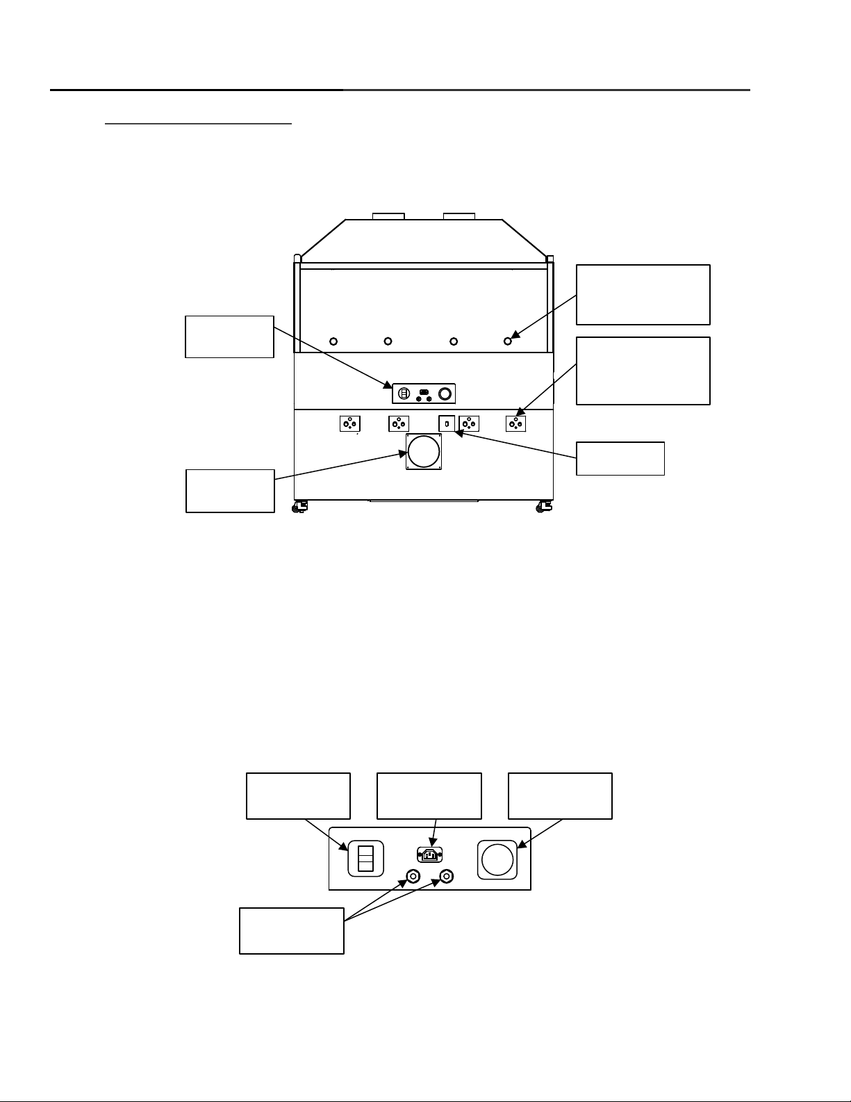
The X-Pro II Workstation requires the following utilities for operation. Locations for connections
are shown in the figure below.
Facilities Requirements – Rear Connections
1. Bake Module Exhaust – External port for bake plate fumes. Exhaust port is 2” OD
2. Spin Bowl Exhaust / Drain – External port for spin bowl vapors and liquid drain. Exhaust
port is 1 Inch OD and 50 CFM of exhaust is recommended. Drain port is ¾” OD and is
intended to be connected to a house drain or other collection vessel.
3. Chemical Cabinet Exhaust – External port for chemical cabinet ventilation. Port is 8” OD
4. Ethernet – The ethernet can be used for remote recipe writing and remote control (see
DataStream™ Manual)
Facilities Requirements – Power Connection Detail
Page 8 of 14
Page 9
Process Module
Station 1
Process Module
Station 2
Process Mod ule
Station 4
Process Module
Station 3
EMO
Emergency
Machine Off
Cee® X-Pro II Workstation Manual
1. System Circuit Breaker – Electrical protection for entire X-Pro II workstation
2. Powered FFU – Power supply for powered Fan Filtered Unit (HEPA / ULPA), if equipped
3. Power In – AC Mains power connection for the X-Pro II workstation
4. System Vacuum / N2 Connections – ¼” NPT (National Pipe Taper) threaded connection
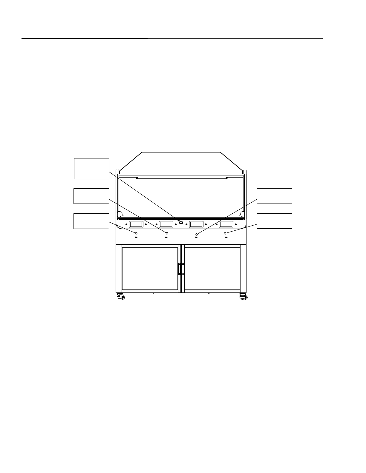
Front / User Connection Detail
1. EMO – Emergency Machine Off – Immediately shuts down all process functions in all
process modules in the X-Pro II Workstation.
2. Process Module Station 1 - 4 – Individual stations populated with Apogee process modules
and user interface controls.
Page 9 of 14
Page 10
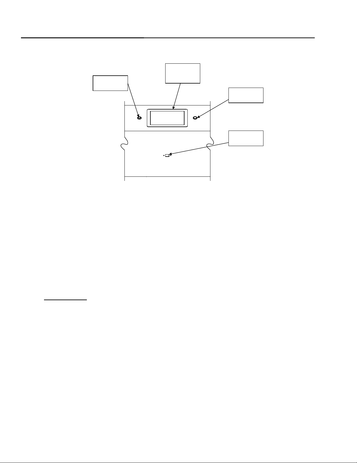
Modul e Power
On/Off
Module
Touchscreen
Interface
Module
Local Presence
Module
USB Interface
Cee® X-Pro II Workstation Manual
1. Module Local Presence – Momentary pushbutton switch to ensure a local presence at the
station versus running the module under remote control. See the relevant process module
manual for more information.
2. Module Touchscreen Interface – Touchscreen used for interacting with all process module
functions.
3. Module Power On/Off – Pushbutton toggle switch to turn an individual process module on or
off.
4. Module USB Interface – USB 2.0 data port for transferring process or recipe data between
the process module and a personal computer
3.3. Environment
The X-Pro II Workstation should be operated in a clean, low humidity / climate-controlled
environment.
Page 10 of 14
Page 11
3.4. Unpacking/Inspection
Thoroughly check machine for shipping damage. If physical damage is seen, DO NOT APPLY
POWER! Contact Cee™ Customer Support immediately.
The following items should be included with the shipment.
(1) X-Pro II Workstation
Optionally included items:
Spin Chucks with Screws
Dispense Controllers
Dispense Pumps or other dispense supply vessels
Dispense Valves
Dispense Nozzles
Dispense Hubs
Bake Plate Stop Pins
Mains power supply cables and / or connectors
3.5. System Installation and Setup
1. Open the shipping crate by removing phillips-head screws
and removing side panels. Lift the unit off the packing
crate base using assistance as required. The X-Pro II
workstation is an extremely heavy piece of equipment
which will likely require machinery such as a forklift to
safely unpack and move.
2. The X-Pro II Workstation has 4 leveling feet that also have
castors. Pull the leveling feet up by turning the orange nut.
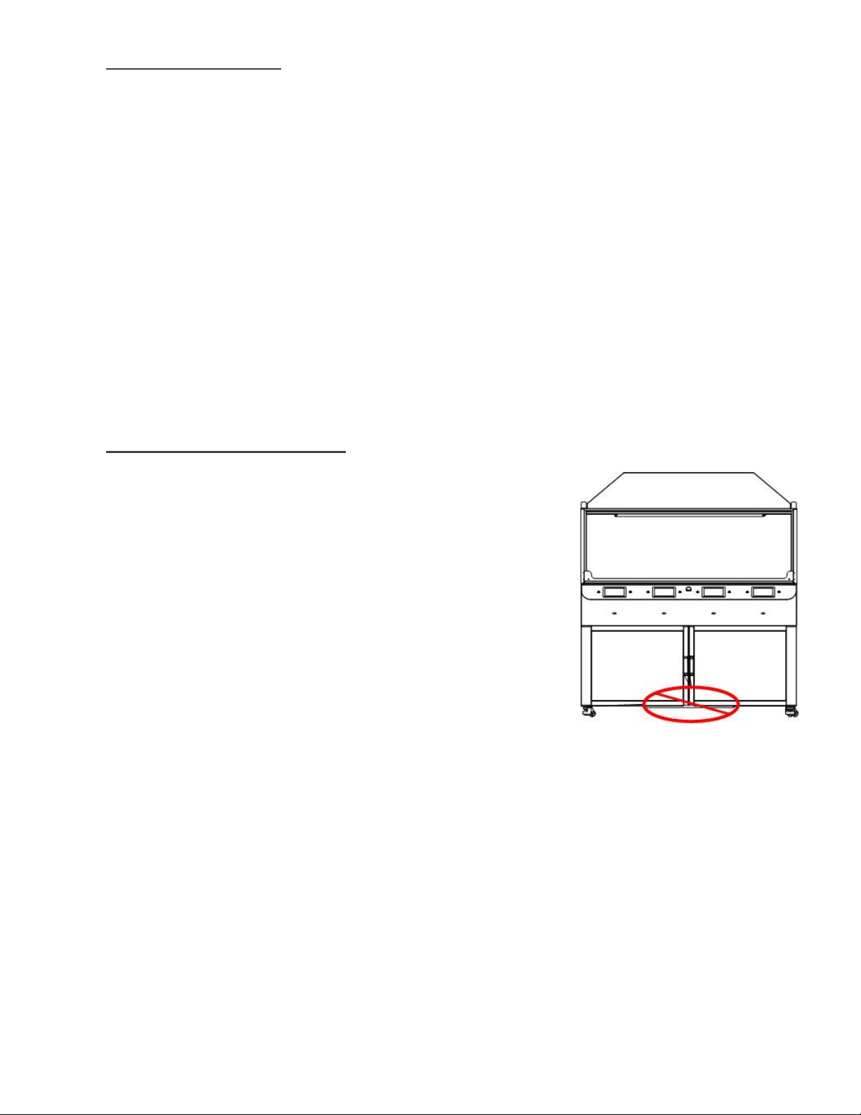
3. Do not lift the by any of the moveable covers or other
handles / protrusions. Do not lift by the cabinet doors. Do
not tip or turn the unit on its side or ends. Lift only from
underneath from the sides. Do not lift from the area
located in the picture to the right. There is no frame work located in this section.
4. Remove plastic wrap and packing foam.
5. Place Cee™ X-Pro II Workstation on a level floor of sufficient strength so that the controls
and spin chuck are at the proper ergonomic height.
6. Level the machine using the feet so that the spin chuck and bake plate surfaces are level
front-to-back and side-to-side.
7. Thoroughly clean all process areas of the X-Pro II Workstation modules and the exterior of
the X-Pro II workstation. See section 3.10 for more information regarding cleaning your
X-Pro II Workstation.
Page 12

8. Connect utilities to the reference diagram in Section 3.7.2
(1) Connect the system vacuum supply to the vacuum fitting
(2) Connect the system nitrogen supply to the nitrogen fitting
(3) Connect any supplied spin module drains to the house-supplied drain facility
(4) Connect any supplied spin module exhaust ports to the house-supplied exhaust
facility.
(5) Connect any supplied bake module exhaust ports to the house-supplied exhaust
facility.
(6) Connect any supplied spin dispense or other accessory item as indicated in reference
documentation.
9. Connect any dispense as indicated on the separate dispense diagrams.
10. Plug in the machine. Note: Unless otherwise specified, there is no LOTO (Lock Out – Tag
Out) facility provided for supplied utilities to the X-Pro II workstation. It is the responsibility
of the customer / end user to install a LOTO device to all supplied utilities as required by
their local laws or company regulations.
3.6. Start Up
1. Install the X-Pro II Workstation tool as shown earlier in this document
2. Perform any initial setup or other preparation steps as required or outlined in the supplied
documentation for the modules fitted in your X-Pro II Workstation.
3. If the tool passes these checks, the tool is ready to operate.
4. Please refer to the figure below for the location and identification of the various user controls
related to the X-Pro II Workstation process modules.
Page 13

4. Preventative Maintenance
Maintenance Section
Maintenance Schedule
Safety Checks
Before daily tool use
Cleaning
After daily tool use
Mechanical Checklist
See Section 4.2 for Details
Utility Checks
See Section 4.3 For Details
This maintenance manual provides personnel with procedure and guidelines for maintaining a
Cee® X-Pro II Workstation. Below is a chart of recommend maintenance scheduling.
4.1. Safety Checks
Inspect the X-Pro II Workstation for the following defects:
(a) Missing or loose exterior panels or guards
(b) Improper operation of sash or other movable guards
(c) Proper connection of utility connection facilities such as system nitrogen,
system vacuum, and module exhaust facilities.
4.2. Mechanical Checklist
Vacuum liquid trap: There should be no material in the vacuum trap. Material in the vacuum
trap will cause vacuum issues. Quarterly (Spin Modules Only – If Equipped)
4.3. Utility Checks
1. Check all pressures for ranges specified in tool manual. Daily
2. Verify that there is a proper drain facility. Daily
3. Verify that the exhaust is functioning. Daily
4. Inspect all connections for proper installation. Bi-Annually
5. Verify that the AC power is of the proper voltage, and is connected. Bi-Annually
4.4. Cleaning
For cleaning, it is good practice to use the mildest solvent possible. The X-Pro II Workstation
cabinet and frame may be cleaned using most organic solvents, acetone, isopropyl alcohol, or
N-methylpyrrolidinone (NMP). Caustic acids or bases should not be used.
For cleaning the individual process modules, please refer to the supplied documentation for
your specific modules and / or module configuration.
Avoid getting solvent of any kind on the warning labels. Use only water-based cleaner on the
labels on the rear of the machine. Use only isopropyl or water-based cleaner on the "power onoff", Cee® logo, and the "Cee® model/serial number" labels. The display may be cleaned with
glass cleaner, water, or isopropyl alcohol.
Page 14
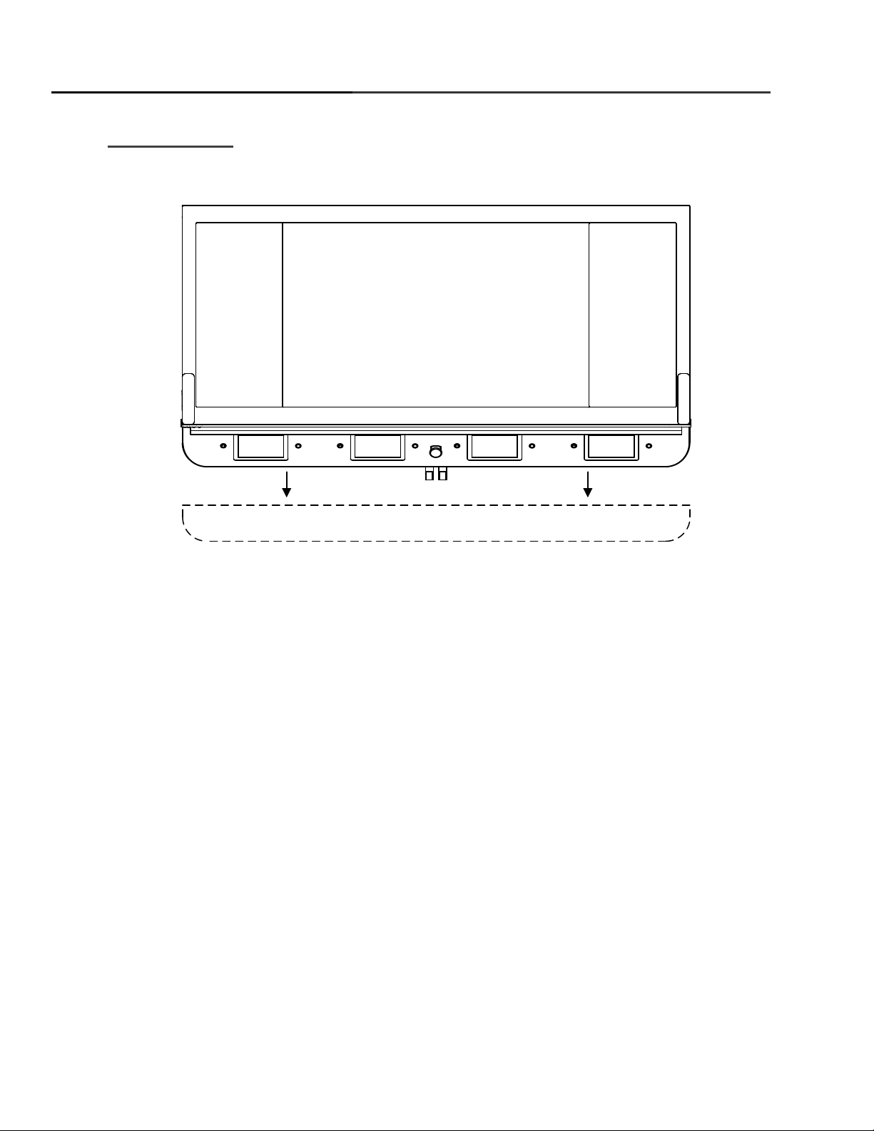
Extended position for module service
Cee® X-Pro II Workstation Manual
4.5. Service Access
For convenient service access to the process modules, the user interface panel can be slid
forward. To release the panel, open the access doors to the chemical storage section of the
X-Pro II Workstation. The user interface panel is held in place by two metal clips that can be
released by unthreading the fixing screws that hold the clips in place. Once the clips are free,
the user interface panel will slide outward, away from the X-Pro II Workstation frame, on roller
slides.
When the necessary maintenance / repairs have been completed, close the user interface
panel and reattach the holding clips and fixing screws. Take care to ensure that no cables are
pinched anywhere along the length of the user interface panel before tightening the fixing
screws to hold the clips and panel in place.
Additional service access may be obtained by removing the plastic side panels of the X-Pro II
Workstation. These panels are easily removed with a slotted screwdriver by turning the slotted
panel hardware ¼ turn until it releases and pops free from the surface of the panel. When all
fasteners have been released the panel can be pulled from the X-Pro II Workstation frame.
Ensure that all electrical power, compressed gasses, and other energy sources are shut off
and suitable disconnected before removing any panels or performing any service on the X-Pro
II Workstation or process modules. Ensure that all panels are fitted and locked into place
before restoring utility service. Failure to observe these guidelines may result in damage to the
X-Pro II Workstation, injury or death.
Page 14 of 14
 Loading...