

Page 1
1
Cee
®
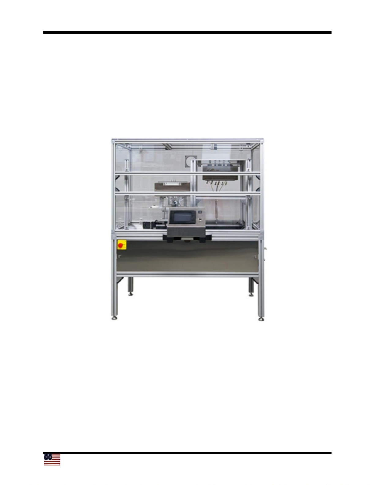
1300CSX
Thermal Debonder
Operator/User Manual
New users: Read this manual in its entirety before operating the equipment.
© 2019 Cost Effective Equipment, LLC
Page 2

2
Contents
1. Products Covered in This Manual .................................................. 3
2. Confidentiality Statement, Warranty, and Instructions
for Returning Materials ......................................................................... 3
2.1 Confidentiality Statement ..................................................................................... 3
2.2 Warranty ............................................................................................................... 3
2.3 Instructions for Returning Materials ...................................................................... 4
3. Introduction to the Cee® 1300CSX Thermal Debonder ...... 5
3.1 Programmability ................................................................................................... 5
3.2 Precision .............................................................................................................. 5
3.3 Reliability .............................................................................................................. 5
3.4 Utilities .................................................................................................................. 6
3.5 Dimensions .......................................................................................................... 6
4. Software ......................................................................................................... 7
4.1 Startup and Run Screen ....................................................................................... 7
4.1.1 Startup with Passwords Enabled ............................................................... 7
4.1.2 Home Slide Button .................................................................................... 7
4.1.3 Run Screen ............................................................................................... 8
4.2 Debonding Process Screen .................................................................................. 9
4.2.1 Running a Debonding Process .................................................................. 11
4.2.2 Loading a Substrate .................................................................................. 12
4.2.3 Starting a Debonding Process ................................................................... 13
4.2.4 The Debonding Process Flow ................................................................... 13
4.2.5 Aborting a Process .................................................................................... 15
4.2.6 Continuing a Process ................................................................................ 15
4.3 Recipe Manager (Edit) Screen ............................................................................. 16
4.3.1 Writing a Recipe ........................................................................................ 18
4.3.2 Entering Data ............................................................................................ 18
4.3.3 Recipe Management ................................................................................. 19
4.3.4 Recipe Backup .......................................................................................... 20
4.4 Diagnostics Screen .............................................................................................. 21
4.4.1 Debonder Diagnostics Screen ................................................................... 22
4.5 User Configuration Screen ................................................................................... 30
4.5.1 Debonder User Configuration Screen ....................................................... 32
4.5.2 Password Configuration Screen ................................................................ 34
4.5.3 User Level Access ..................................................................................... 34
4.6 Navigation Bar ...................................................................................................... 35
Page 3

3
1. Products Covered in This Manual
This manual covers the Cee® 1300CSX thermal slide debonder. This manual is to be
used to install, operate, and troubleshoot the 1300CSX debonder. New users should
read this manual in its entirety before operating the equipment.
2. Confidentiality Statement, Warranty, and Instructions for
Returning Materials
2.1 Confidentiality Statement
Information supplied is only for use during operation and/or maintenance of Cee®
equipment. Neither this document nor the information it contains shall be
disclosed to others for manufacturing or any other purpose without written
authorization from Cost Effective Equipment, LLC.
2.2 Warranty
Cost Effective Equipment, LLC (Cee), warrants to the original purchaser (Buyer) that the
equipment is free from defects in material and workmanship under normal use and
service in accordance with Cost Effective Equipment, LLC instructions and
specifications.
Buyer shall promptly notify Cost Effective Equipment, LLC of any claim against this
warranty, and any item to be returned to Cost Effective Equipment, LLC shall be sent
with transportation charges prepaid by Buyer, clearly marked with a Return Material
Authorization (RMA) number obtained from Cost Effective Equipment, LLC Customer
Support. (See section 2.3.)
Cee®’s obligation under this warranty is limited to the repair or replacement, at Cee
®
’s
option, of any equipment, component, or part that is determined by Cee® to be defective
in material or workmanship. This obligation shall expire one (1) year after the initial
shipment of the equipment from Cee®.
This warranty shall be void if:
a) Any failure is due to the misuse, neglect, or improper installation of or accident to
the equipment.
b) Any major repairs or alterations are made to equipment by anyone other than a
duly authorized representative of Cee®. Representatives of Buyer may be
authorized to make repairs to the equipment without voiding warranty upon
completion of the appropriate Cee® equipment training program.
c) Replacement parts are used other than those made or recommended by Cee®.
Page 4

4
COST EFFECTIVE EQUIPMENT, LLC MAKES NO OTHER WARRANTIES,
EXPRESSED OR IMPLIED, WITH RESPECT TO EQUIPMENT. NO WARRANTY IS
MADE AS TO THE MERCHANTABILITY OF THE EQUIPMENT NOR ITS FITNESS
FOR ANY PARTICULAR PURPOSE. In no event shall Cee® be liable for consequential
loss or damages, however caused. No person or representative of Cee® is authorized to
assume for Cee® any liability in connection with Equipment nor to make any change to
this warranty unless such change or modification is put in writing and signed by an
authorized representative of Cee®.
This warranty shall be governed by the laws of the state of Missouri, U.S.A.
2.3 Instructions for Returning Materials
Any materials, parts, or equipment returned to Cost Effective Equipment Customer
Support must be clearly labeled with a Return Material Authorization (RMA) number.
To obtain an RMA number, contact:
Cost Effective Equipment Customer Support
Telephone: (573) 466-4300
E-Mail: [email protected]
Web Address: http://www.
costeffectiveequipment
.com
Shipping information for use in returns with an RMA number:
Cost Effective Equipment, LLC
Attn: Equipment Customer Support
3703 HyPoint Blvd
Rolla, Missouri 65401
USA
Page 5

5
3. Introduction to the 1300CSX Thermal Debonder
The Cee® 1300CSX thermal debonder enables high-temperature slide-off debonding of
thinned wafers in a laboratory setting. This tool permits development engineers to
complete the final step of thinned-full-wafer processing in a confidential developmental
setting. Internal small-scale prototyping capability may be used to accelerate product
development cycles and improve time to market for new ultrathin wafer technologies.
3.1 Programmability
• PC-controlled
• PC-based touch screen interface and display
• Full-color alphanumeric-capable graphical user interface (GUI)
• 250,000 process recipe programs onboard
• A virtually unlimited number of user-defined recipe program steps
• 0.1-second resolution for step times (max. step time: 9,999.9 seconds)
• Connectivity: USB/Ethernet port for communications for uploading/downloading
process parameters with offline firmware standard (offline recipe number and steps
unlimited)
• Security: Password protection option available at no charge
3.2 Precision
• Precision lower platen z-position control (closed-loop control/feedback): ± 0.5 µm
accuracy
• Substrate sizes: 2 inches to 200 mm round
• Temperature resolution: 0.1°C
• Temperature range: ambient to 300°C
3.3 Reliability
• Total throughput < 200 mm: est. 8-14 WPH
• Total throughput ≥ 200 mm: est. 4-8 WPH
• Wafer breakage: < 10% (≥ 90% process yield for compound semiconductor and
silicon)
• System uptime: > 90% over a 12-month period
• MTBF (hours/cycles): > 600 hours, 6,000 cycles
• MTTR: < 24 hours (critical spare parts, as defined by Cee®, to be kept at customer
site per Cee® field service standard working schedule)
Page 6

6
3.4 Utilities
• Electrical: 208 V, single phase, 50/60 Hz, 6500 W
• Exhaust: 30 cfm
• Vacuum: 25 in Hg
• Nitrogen or CDA: 100 psi
3.5 Dimensions
• 49” W × 39.5” D × 52.5” H (125 cm W × 100 cm D × 133 cm H)
• Shipping weight: 187 kg
Page 7

7
4. Software
4.1. Startup and Run Screen
4.1.1 Startup with Passwords Enabled
If the Cee® 1300CSX debonder tool has passwords enabled, the initial screen will only
contain login and logout buttons.
To log in, press the Login button, to view the touch screen keyboard, and then enter
your password. By default, the passwords for a Cee® 1300CSX tool are:
Super User Level: CEE
User Level: 1300CSX
Maintenance: DIAG
4.1.2 Home Slide Button
Once login is complete, or at startup if passwords are not enabled, the Home Slide
button is visible. Pressing this button will move the slide to the home sensor at a high
speed. Once the home sensor detects the bottom platen, the bottom platen will move off
of the sensor and then back onto the sensor at a very slow speed. Once the x-axis slide
has returned to its home position, the z-axis lift platform will return to its home position
by moving up to the end of its stroke and then back to the zero position. Once the
homing sequence is complete, the Run screen appears and a process may be run.
4.1.3 Run Screen
Once the slide has returned to its home position and the user has logged in (if enabled),
the Run screen will appear.
From this screen, the user can go directly to the Debonding Process screen by pressing
the Debonding Process button in the left-center of the screen. Navigating to other
windows is also possible by using the navigation bar at the bottom of the screen.
Page 8
8
4.2 Debonding Process Screen
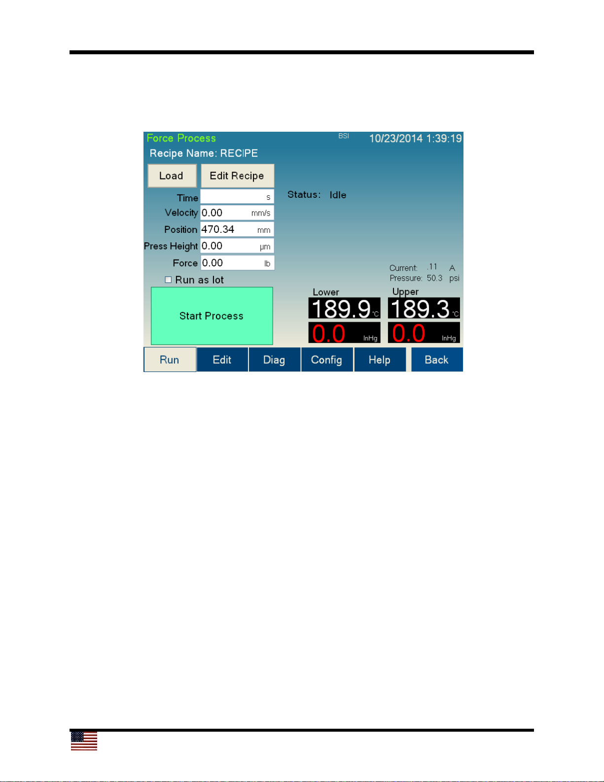
The Debonding Process screen is used to run and monitor debonding processes using
the Cee® 1300CSX tool’s software.
1
12
9
8
7
6
5
43
13
1411
10
2
The controls and indicators found on the Debonding Process screen are listed below:
1. Recipe Name: The name of the currently loaded recipe
2. Status: Describes the current status of the debonding process
3. Load button: Navigates to the recipe selection screen (section 4.2.1) to select the
process settings
4. Edit Recipe button: Navigates to the Debonding Process editor if a recipe is
loaded. If a recipe is not loaded, navigates to the recipe selection screen (section
4.2.1).
5. Time indicator: Displays the current time remaining of the current process step. Not
all process steps are time-based.
6. Velocity indicator: Shows the current speed of the lower platen
7. Position indicator: Shows the current position of the lower platen along the slide
8. Press Height indicator: Shows the current height of the bottom platen
9. Force indicator: Shows the current x-axis (lateral) force being applied at the bottom
platen
Page 9
9
1
12
9
8
7
6
5
43
13
1411
10
2
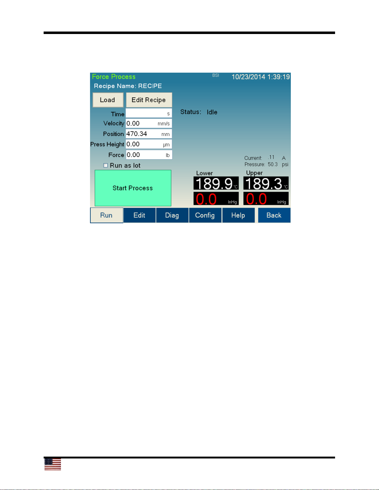
10. Process button: The process button has three modes:
a. Start Process: Starts the debonding process. The user will be prompted to
load the substrate at the appropriate time.
b. Abort: Aborts a currently running process.
c. OK: Turns off the Process Complete alarm.
11. Run as lot check box: Checking this box will cause the tool to begin the same
process as soon as the previous process was completed. Checking this box
eliminates the need for the user to press Start Process a second time. This check
box will only appear if the tool is set to Production Mode on the User Configuration
screen (section 4.5).
12. Temperature and Vacuum display: Shows the current temperature and vacuum
level of both platens.
13. Current display: Shows the current on the z-axis lift.
14. Pressure display: Shows the current system pressure.
Page 10
10
4.2.1 Running a Debonding Process
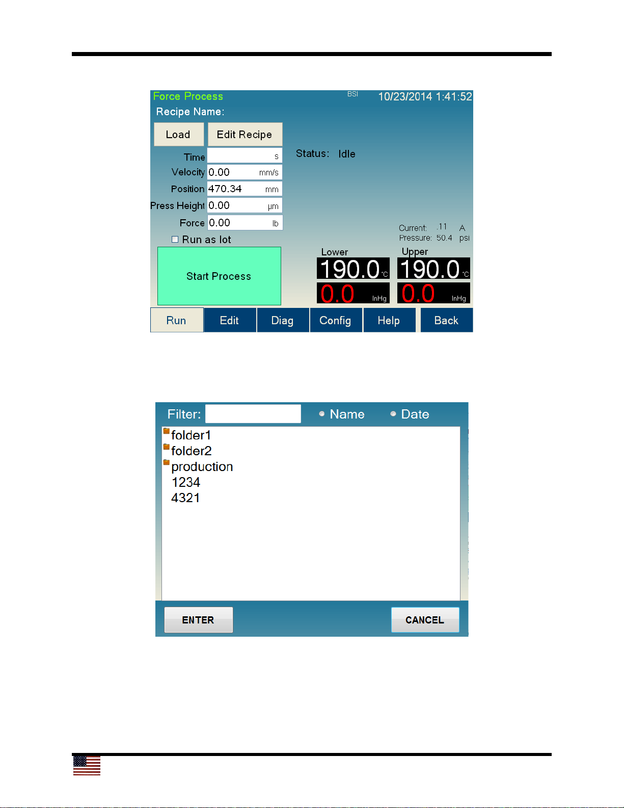
To run a debonding process, a recipe must first be loaded. Pressing the Load button will
bring up the recipe selection screen (see below). To select a recipe, double-press on
the desired recipe, or select the desired recipe and press Enter.
Page 11
11
4.2.2 Loading a Substrate
The Cee® 1300CSX tool will prompt the user to load a substrate at the appropriate time
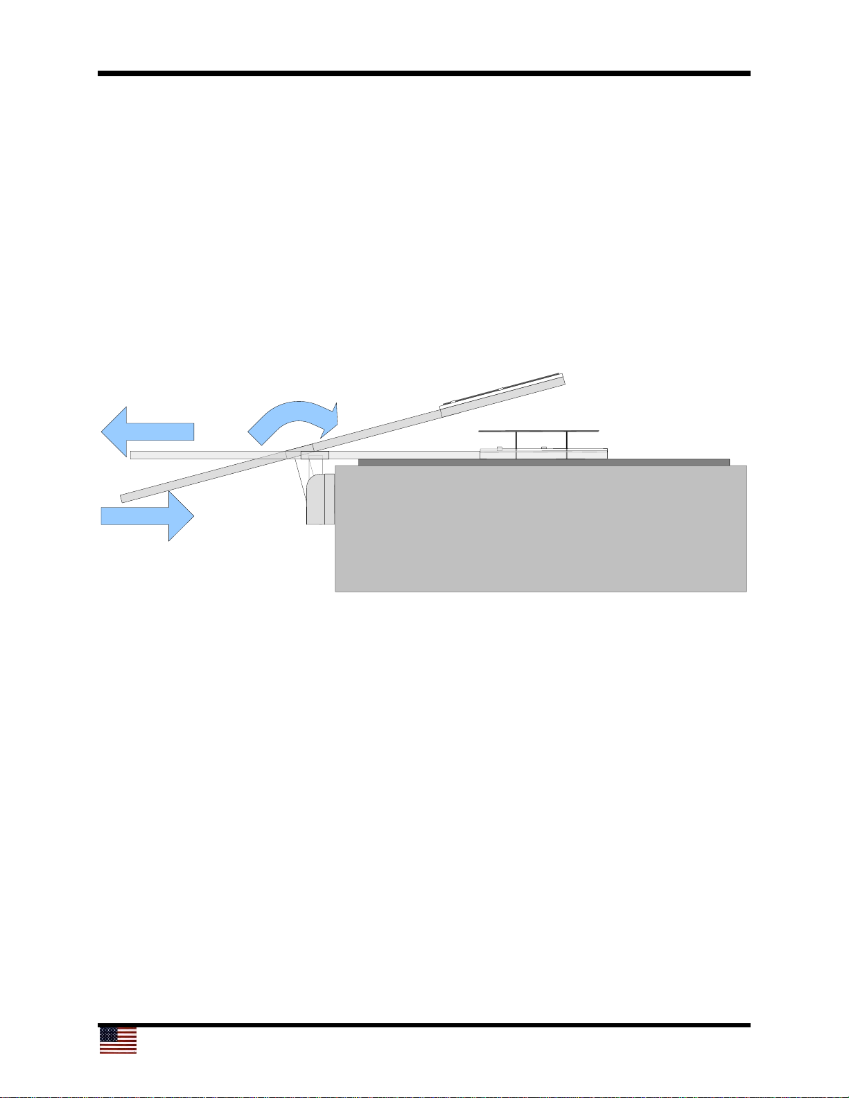
after the Start Process button is pressed. The process to load a substrate is as follows:
1. Place substrate on proper loading arm with the notch or flat to the right.
2. Insert loading arm with substrate into the alignment pocket on the lower platen at
the angle shown below. Be sure the substrate does not move on the loading arm.
3. Rotate the arm forward until the substrate is lifted off the loading arm.
4. Carefully pull out loading arm without bumping the substrate.
5. Visually check that the substrate is centered.
6. Press Continue at the user prompt.
2
4
3
Page 12
12
4.2.3 Starting a Debonding Process
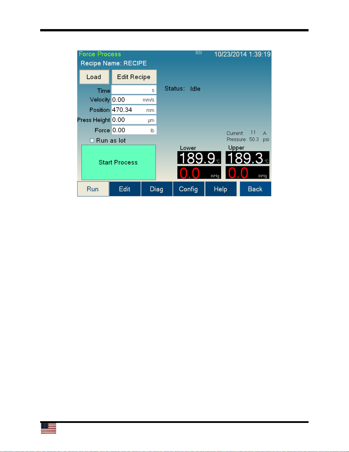
Press the Start Process button to begin a debonding process. The tool will initiate a
sequence of prompts to get the substrate successfully loaded onto the lift pins. This
sequence is as follows:
1. Press the Start Process button.
The lower platen will go to home position and lift pins will rise.
The user will be prompted to load the substrate. See section 4.2.2.
2. Confirm loading by pressing OK on the prompt.
3. Wait for “Lift Pin Delay” from recipe.
Lift pins will lower.
4. Wait for “Pre Vac Delay” from recipe.
Vacuum is initiated, and the tool checks for substrate.
5. Wait for “Lower Plate Delay” from recipe.
6. Process begins.
Page 13

13
4.2.4 The Debonding Process Flow
The flow of the debonding process is as follows:
1. The lower platen moves under the upper platen.
2. The lower platen moves up to the vacuum search window start position
determined by “Stack Thickness” and “Search Distance.”
3. Upper platen vacuum is turned on.
4. The lower platen will continue to move up by increments specified by “Step
Distance” in the recipe.
5. If vacuum is found on the upper platen, the lower platen will halt. If no vacuum is
found, the lower platen will recover and move back to the loading position.
6. The process will wait for the time specified by thermal stabilization (Press Up) in
the Recipe Manager screen.
7. The lower platen will then move toward the home position using the force
specified in the recipe, limited by the maximum speed, which is also specified by
the recipe.
8. Once the substrates have debonded, the lower platen will lower to its home
position, and then the slide will return to the home position.
9. The user will be prompted to insert the extraction tool. When the sensor detects
the extraction tool, the substrate on the upper platen will be released.
10. The user may then remove the substrate from the lift pins on the bottom platen.
11. The tool will ask the user to acknowledge when all extraction tools are clear of
the Cee®1300CSX tool. This acknowledgment concludes the process.
Page 14
14
4.2.5 Aborting a Process
After a process has started, pressing the Abort button, EMO, or breaking the light
curtain will abort the process. Aborting a process will halt the Cee® 1300CSX tool in its
current state and will allow the user to go into Diag mode and attempt manual
debonding to save the substrate. When the EMO has been pressed, the Cee® 1300CSX
tool must be restarted to appropriately recover.
4.2.6 Continuing a Process
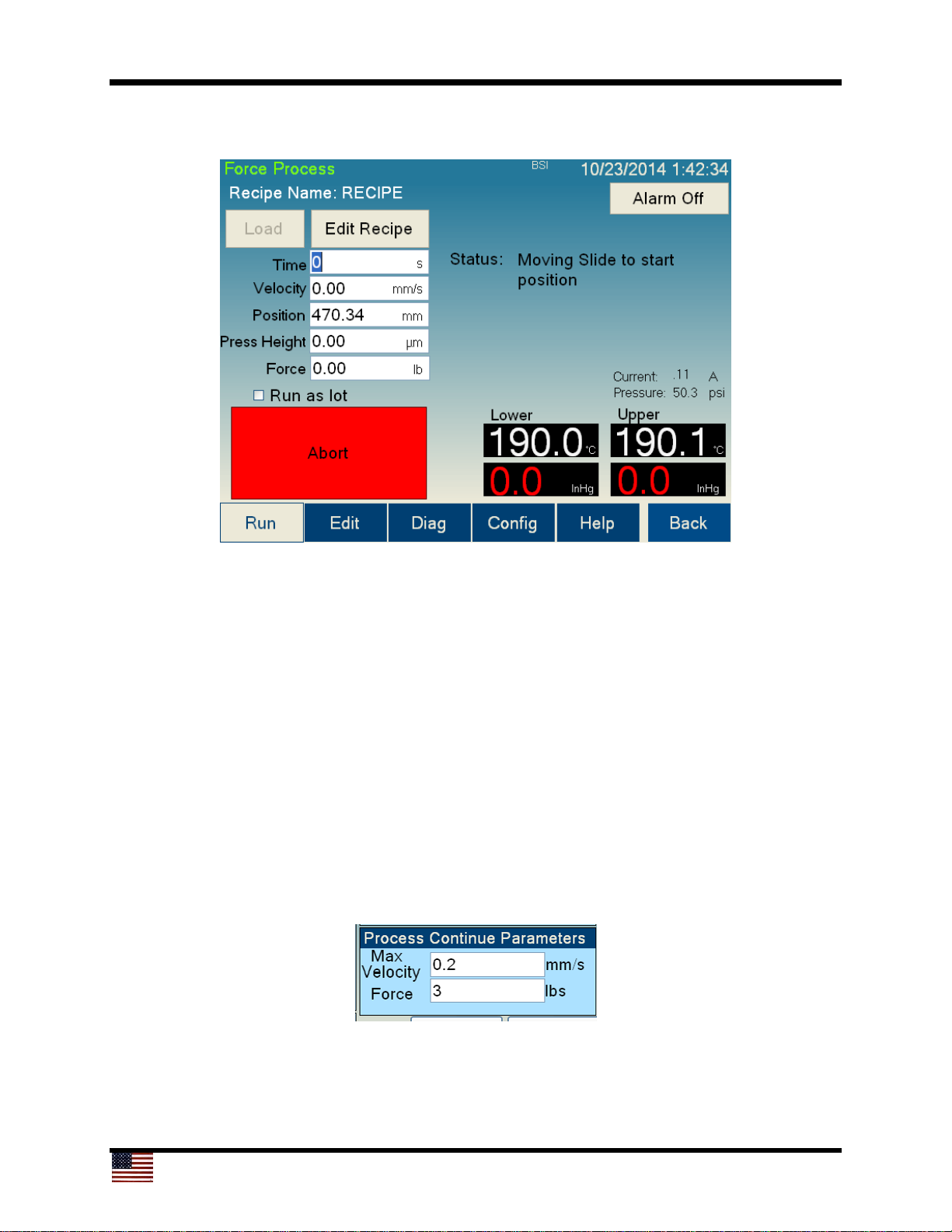
A process can be aborted for several reasons (user abort, low vacuum, speed too high,
force too high, light curtain broken, emergency off [EMO], etc.). If the process is aborted
by either the user or the software, the tool will pause and offer the user a chance to
continue or abort. If the user chooses to continue, the process will try to continue by
ignoring hardware signals to abort; however, the Abort button will stay active. When the
process continues, the software will ignore the recipe values for force and maximum
speed and instead use the parameters specified in the Config screen (section 4.5.1).
This feature allows the user to enter safe values (lower Max Velocity and lower Force)
to try to continue debonding a substrate stack after the process was aborted. The tool
must be monitored during this portion of the run, however, because the tool will ignore
further alarms such as the one for low vacuum.
Page 15
15
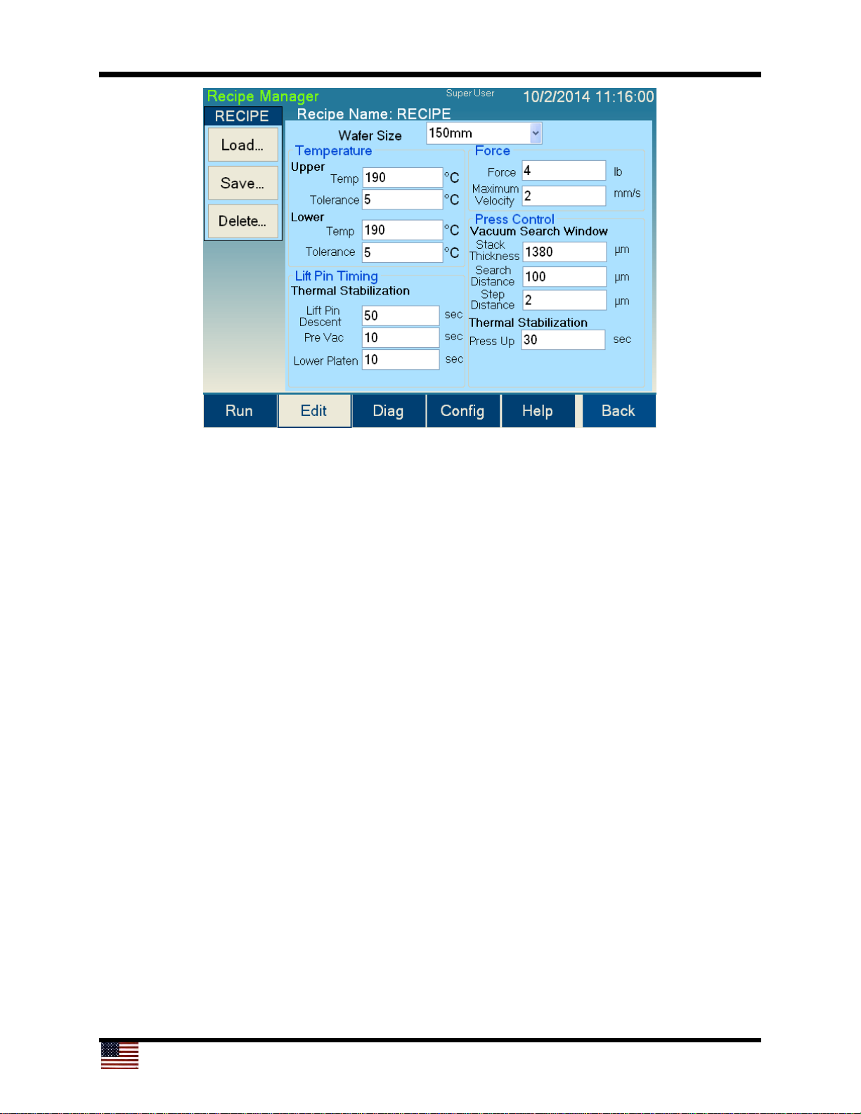
4.3 Recipe Manager (Edit) Screen
To navigate to the Recipe Manager (Edit) screen, press the Edit button located on the
lower navigation panel.
1
2
3
4
5
6
7
8
9
10
11
12
13
14
15
16
17
18
The controls and indicators found on the Recipe Manager (Edit) screen are listed below:
1. Recipe Name: The name of the currently loaded recipe
2. Load button: Opens the dialog to load a recipe into the editor
3. Save button: Opens the save dialog for saving the current recipe
4. Delete button: Opens the delete dialog for deleting recipes
5. Substrate size dropdown menu: A dropdown menu for selecting the substrate size
(each Cee® 1300CSX tool may be configured for different sizes)
6. Upper platen Temperature: The temperature for the upper platen
7. Upper platen Tolerance: The temperature tolerance of the upper platen beyond
which an error will occur
8. Lower platen Temperature: The temperature for the lower platen
9. Lower platen Tolerance: The temperature tolerance of the lower platen beyond
which an error will occur
Page 16
16
1
2
3
4
5
6
7
8
9
10
11
12
13
14
15
16
17
18
10. Lift Pin Descent: The time the lift pins will take to descend from their up position
down to the platen
11. Pre Vac delay: The time the substrate will rest on the lower platen before vacuum is
applied
12. Lower Platen delay: The time the substrate will rest on the lower platen before
beginning the process
13. Force: The x-axis (lateral) force applied to the substrates for debonding
14. Maximum Velocity: The maximum speed the slide will operate even if the force
specified in the recipe is not required
15. Stack Thickness: The thickness of the bonded substrates prior to debonding
16. Search Distance: The overall distance the lower platen moves while searching for
vacuum on the upper platen
17. Vacuum Search Step Distance: The vertical distance the lower platen will rise
between stopping to try to detect a vacuum
18. Press Up delay: The time that the Cee® 1300CSX tool will delay after finding
vacuum on the upper platen before attempting to debond
Page 17
17
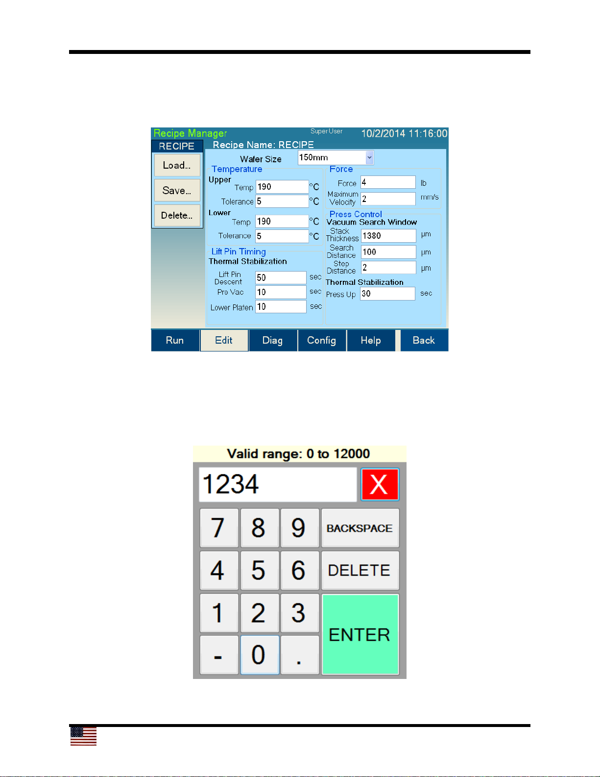
4.3.1 Writing a Recipe
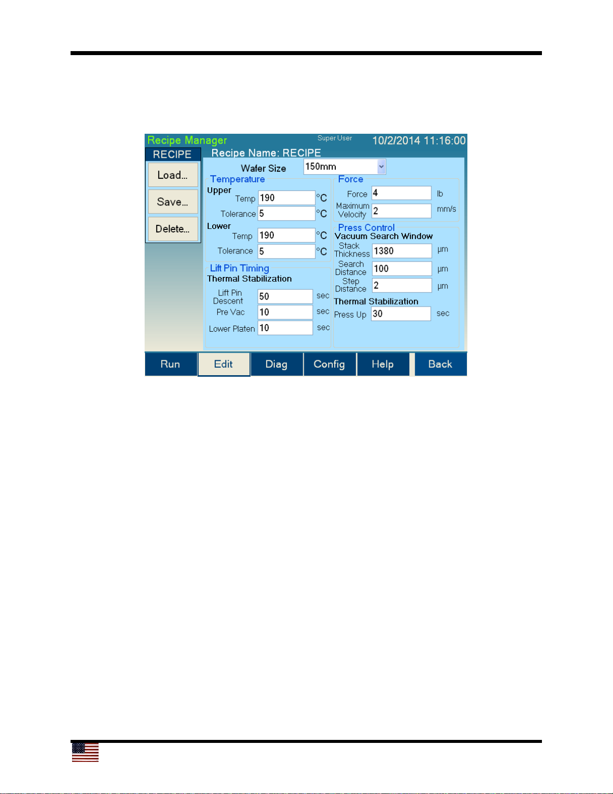
Recipes are entered in the Recipe Manager screen (accessible by pressing the Edit
button in the bottom navigation bar), shown below.
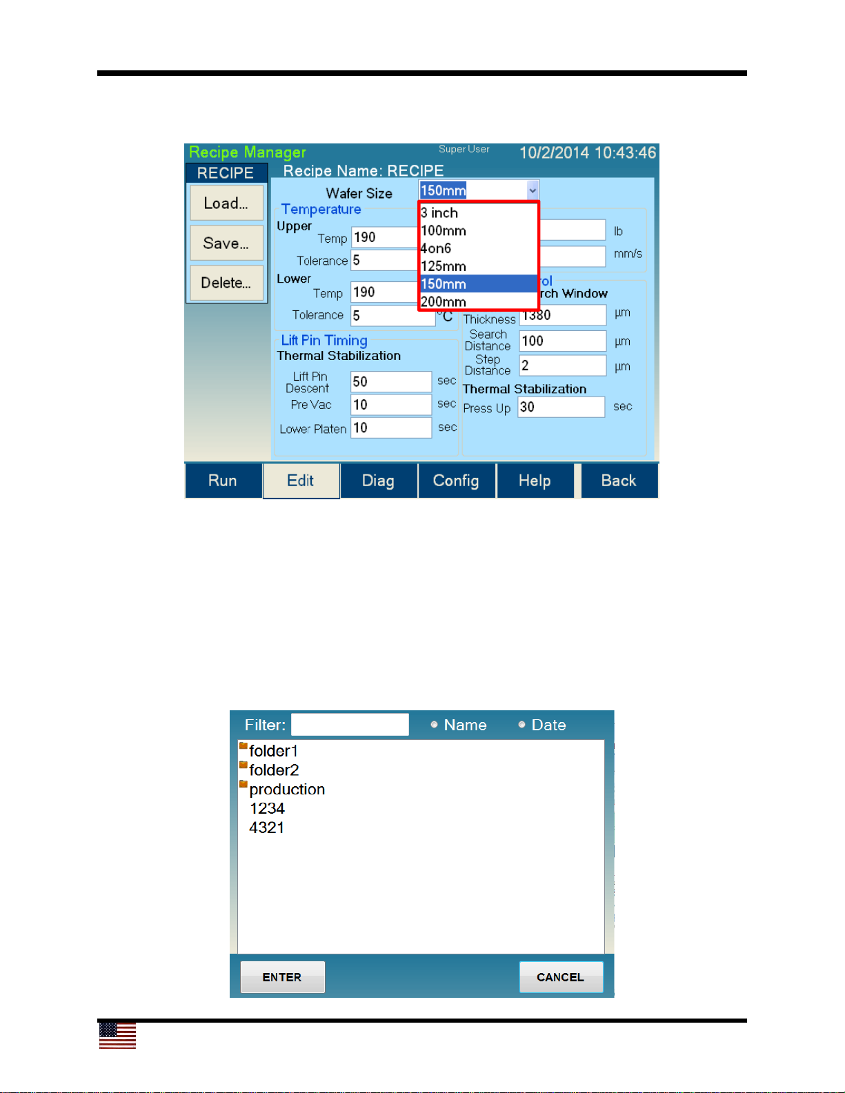
4.3.2 Entering Data
By selecting the any text box (items 6 through 18 in the screen shown in section 4.3
above), a numeric pad will appear, as shown below.
Using the numeric pad, the user can now enter the parameter for the selected step. The
valid range for the specific type of value will be provided above the number pad. Once
Page 18
18
the desired value is entered, pressing the ENTER key will close the numeric pad and
return to the Recipe Manager screen with the selected value updated.
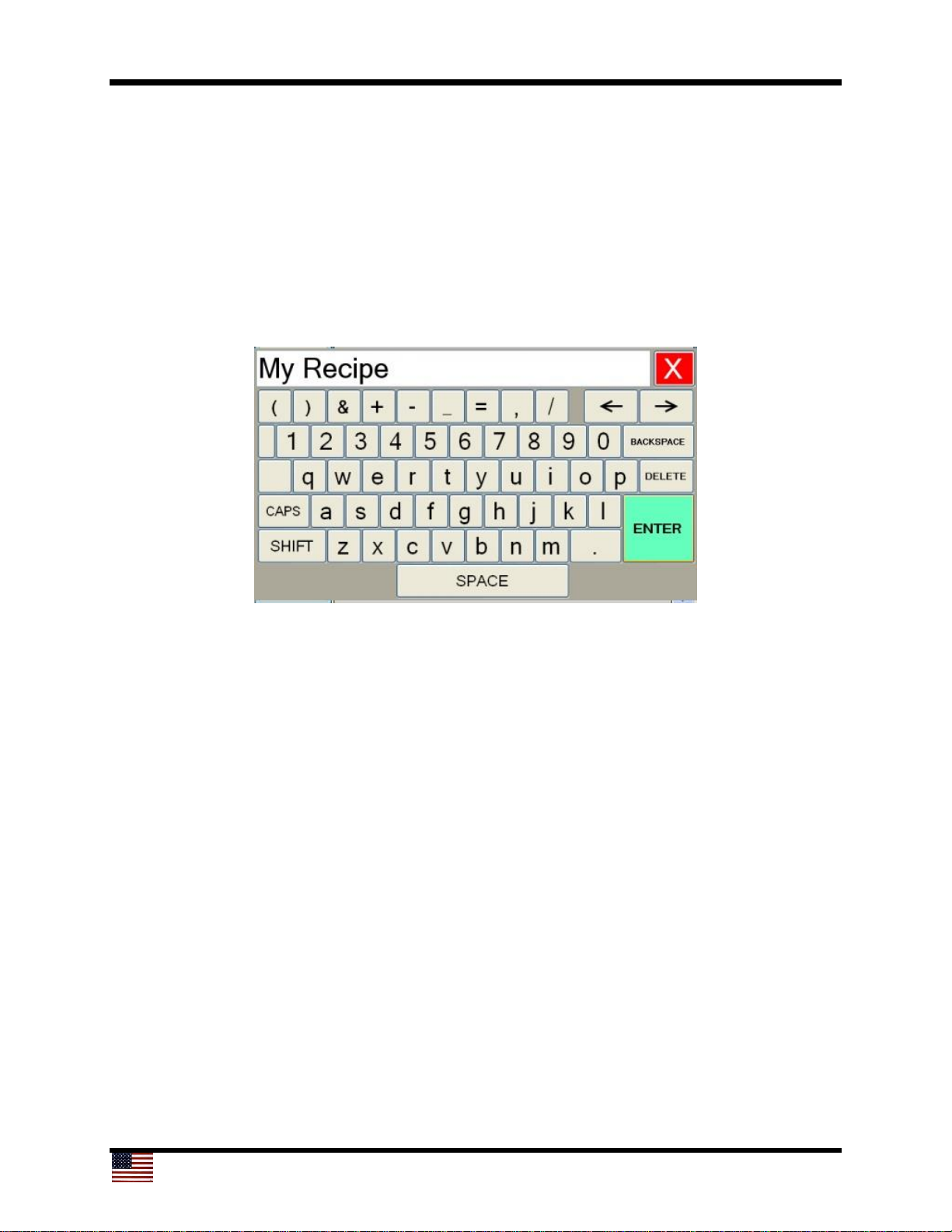
When the small arrow at the right of the wafer size selection box at the top of the
window is clicked, a dropdown box will allow the user to select the correct wafer size.
4.3.3 Recipe Management
Recipes are managed by the Load, Save, and Delete buttons (items 2, 3, and 4 in the
screen shown in section 4.3). To load a saved recipe, press the Load button, which will
bring up the Recipe Select screen, as shown below.
Page 19
19
The recipe can be loaded into the editor by pressing a recipe name and then pressing
Enter, or by double-pressing a recipe name.
To delete a saved recipe, press the Delete button, which will also bring up the Recipe
Select screen. The recipe can be deleted by pressing a recipe name and then pressing
enter, or by double-pressing a recipe name.
To save a recipe, press the Save button, which will bring up an on-screen keyboard
(see below) for entering the recipe name. Enter the desired recipe name using the
keyboard, and then press the Enter key, which will save the recipe with the desired
name.
4.3.4 Recipe Backup
Recipes are saved in comma separated value (.csv) format. The Cee® 1300CSX tool
uses a Windows® operating system. The debonding recipes are saved in the
c:\Cee\Force folder in the Windows® file system. To back up recipes, copy recipe files
to a storage device via the front USB port. Alternatively, files can be transferred via the
Ethernet port on the back of the tool. By default the Cee® 1300CSX tool is set up as IP
address 192.168.1.1, and the recipe folder is shared as a network store.
Page 20
20
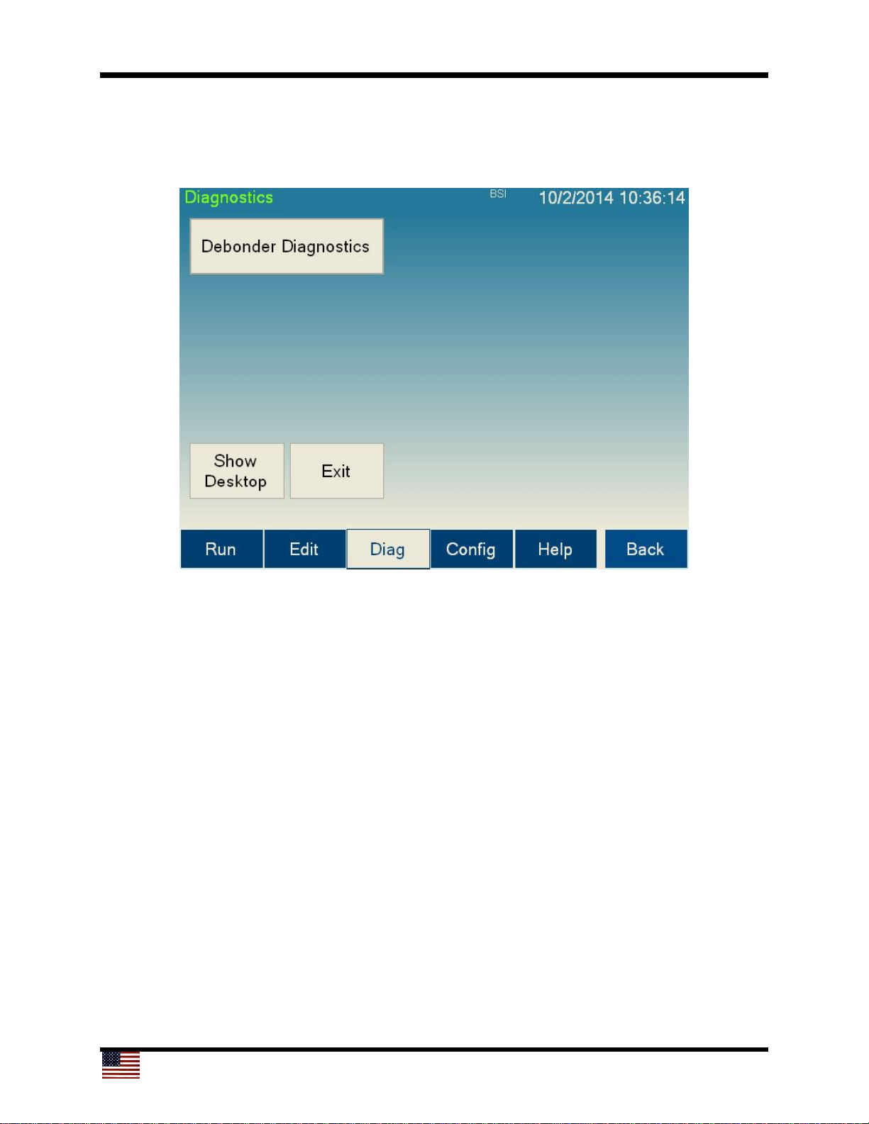
4.4 Diagnostics Screen
The Diagnostics screen allows manual operation of most of the hardware on the
Cee® 1300CSX debonding tool.
The controls and indicators found on the Diagnostics screen, shown above, are listed
below:
1. Debonder Diagnostics button: Navigates to the Debonder Diagnostics screen
2. Show Desktop button: Minimizes the Cee® 1300CSX tool control software, which
allows display of the Windows® desktop
3. Exit button: Closes the Cee® 1300CSX tool control software and exits to the
Windows® desktop
Page 21
21
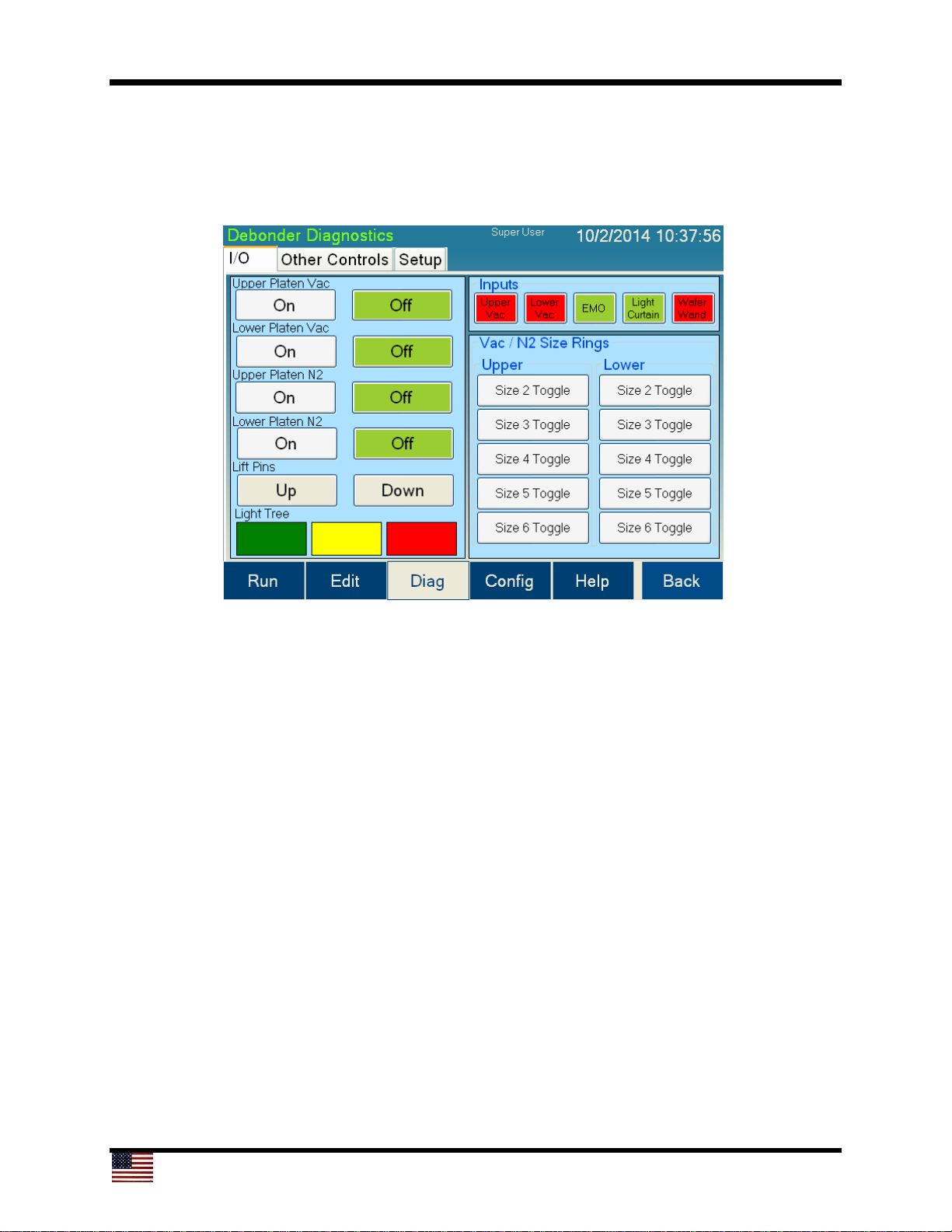
4.4.1 Debonder Diagnostics Screen
The Debonder Diagnostics screen allows manual operation of most of the hardware on
the Cee® 1300CSX tool. The controls are contained on three tabs.
1
2
3
4
5
7 8 9 10 11
12 13
6
The controls and indicators found on the I/O tab of the Debonder Diagnostics screen
are listed below:
1. Upper Platen Vac On and Off buttons: Turn on or off the vacuum on the upper
platen. The current state will be highlighted.
2. Lower Platen Vac On and Off buttons: Turn on or off the vacuum on the lower
platen. The current state will be highlighted.
3. Upper Platen N2 On and Off buttons: Turn on or off the nitrogen on the upper
platen. The current state will be highlighted.
4. Lower Platen N2 On and Off buttons: Turn on or off the nitrogen on the lower
platen. The current state will be highlighted.
5. Lift Pins Up and Down buttons: Raise or lower the lift pins on the lower platen.
6. Light Tree controls: Set the color of the light tree to green, yellow, or red.
7. Upper Platen vacuum display: This box will be green if the current level of vacuum
is higher than the level set in the configuration screen. This box will be red
otherwise.
Page 22
22
1
2
3
4
5
7 8 9 10 11
12 13
6
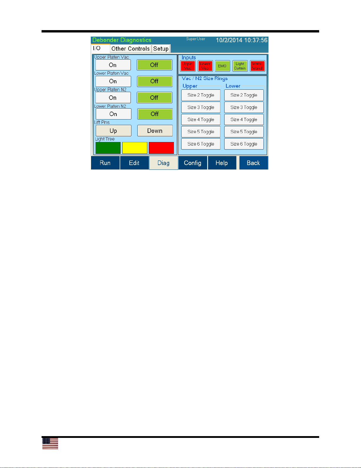
8. Lower Platen vacuum display: This box will be green if the current level of vacuum
is higher than the level set in the configuration screen. This box will be red
otherwise.
9. EMO display: This box will display green if the emergency off (EMO) state is not
interrupted and it is safe to run. If the EMO is interrupted, the box will be red. The
Cee® 1300CSX tool will not operate if this box is red.
10. Light Curtain display: This box will display green if the light curtain is not
interrupted and it is safe to run. If the light curtain is interrupted, the box will be red.
The Cee® 1300CSX tool will not operate if this box is red.
11. Wafer Wand display: This box will display green if the wafer wand is present under
the upper platen. This box will be red otherwise.
12. Upper platen ring toggle: The upper platen has rings that allow the platen to
accept different sizes of substrates. These toggle buttons control which ring sizes
are active when the vacuum or N2 is active. The standard sizes are:
No size: 2-inch substrates
Size 2: 3-inch substrates
Size 3: 100-mm substrates
Size 4: 125-mm substrates
Size 5: 150-mm substrates
Size 6: 200-mm substrates
The boxes will be highlighted in green when active.
13. Lower platen ring toggle: The lower platen has rings that allow the platen to accept
different size substrates. These toggle buttons control which ring sizes are active
when the vacuum or N2 is active. The standard sizes are:
Page 23

23
No size: 2-inch substrates
Size 2: 3-inch substrates
Size 3: 100-mm substrates
Size 4: 125-mm substrates
Size 5: 150-mm substrates
Size 6: 200-mm substrates
The boxes will be highlighted in green when active.
Page 24
24
1
2
3
4
5
6
7 8
9
10
14
13
11
15 16
17
18 19
20
12
21 22
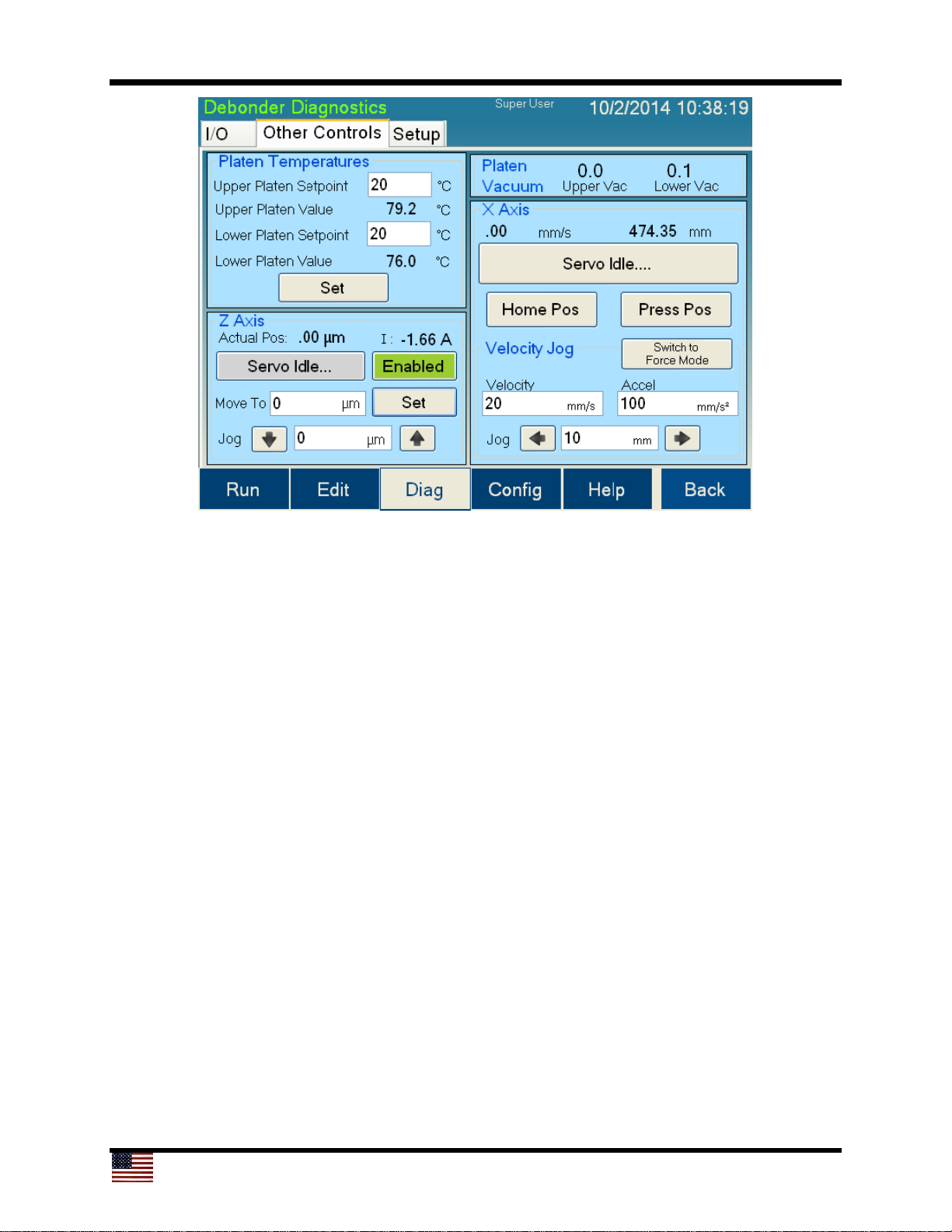
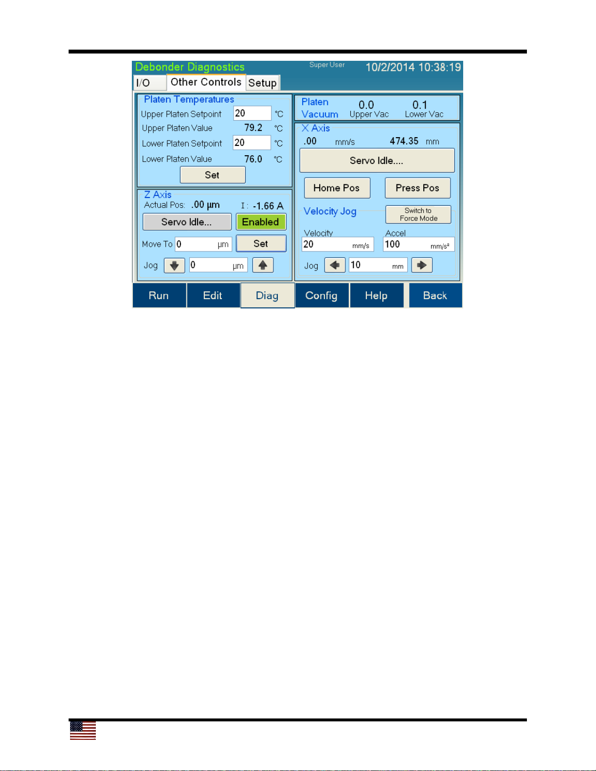
The controls and indicators found on the Other Controls tab of the Debonder
Diagnostics screen are listed below:
1. Upper Platen Setpoint: The setpoint for the temperature on the upper platen
2. Upper Platen Value: The current temperature of the upper platen
3. Lower Platen Setpoint: The setpoint for the temperature on the lower platen
4. Lower Platen Value: The current temperature on the lower platen
5. Temperature Set: Writes the values in (1) and (3) to the temperature controllers and
starts transitioning the platens to the new setpoints
6. Z-Axis status display: The vertical position and current load of the z-axis lift.
7. Z-Axis stop servo button: When the z-axis lift is moving, this button will be red and
display STOP Servo. Pressing the red button will immediately stop the servo. If the
servo is not moving, the button will be gray and display Servo Idle; pressing it will
have no effect.
8. Z-Axis Enabled button: When the z-axis lift is enabled and has no faults, the button
is green and displays Enabled. When a fault has occurred, the button will turn red
and display Re-enable. Pressing the red button will clear all faults and re-enable the
servo. When the button is green, pressing it will have no effect.
9. Z-Axis Move To field and Set button: Enter the desired height in the Move To field
and press set to move the z-axis lift.
Page 25
25
1
2
3
4
5
6
7 8
9
10
14
13
11
15 16
17
18 19
20
12
21 22
10. Z-Axis Jog: Enter the desired jog distance into the Jog field. Press the up-arrow
button to move up and the down-arrow button to move down the entered jog
distance.
11. Upper Vac display: The current vacuum level on the upper platen
12. Lower Vac display: The current vacuum level on the lower platen
13. Servo Status display: The current servo velocity, position, and droop
14. Stop Servo button: When the servo is moving, this button will be red and display
STOP Servo. Pressing the red button will immediately stop the servo. If the servo is
not moving, the button will be gray and display Servo Idle; pressing it will have no
effect.
15. Home Position button: Quickly moves the lower platen on the slide to the home
position
16. Press Position button: Quickly moves the lower platen under the upper platen into
the press position
17. Force/Position toggle button: This button affects items 18, 19, 20, 21, and 22
shown in the screen above. This button toggles between Force and Position mode
control of the slide. Force mode will move the slide at a constant force up to a
maximum speed. Position mode will move the slide a specified jog distance at a
constant speed.
18. Velocity of jog: In position mode, the velocity for the jog. In force mode, the force
for the jog.
Page 26
26
1
2
3
4
5
6
7 8
9
10
14
13
11
15 16
17
18 19
20
12
21 22
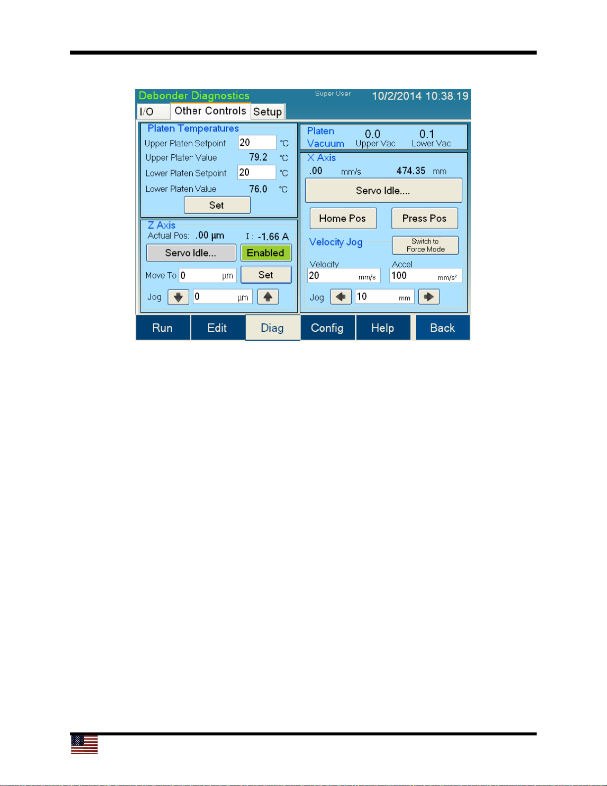
19. Accel for jog: The acceleration for the jog in position mode. Enter the maximum
velocity of the servo for the jog in force mode.
20. Distance to jog: The distance to jog in position mode; has no effect in force mode.
21. Left arrow/Start: In position mode, jogs the lower platen left the distance specified
in the distance to jog field (20); in force mode, starts a force jog.
22. Right arrow/Stop: In position mode, jogs the lower platen right the distance
specified in the distance to jog field (20); in force mode, stops a force jog.
Page 27
27
1
2
3
4
5
6
7
8
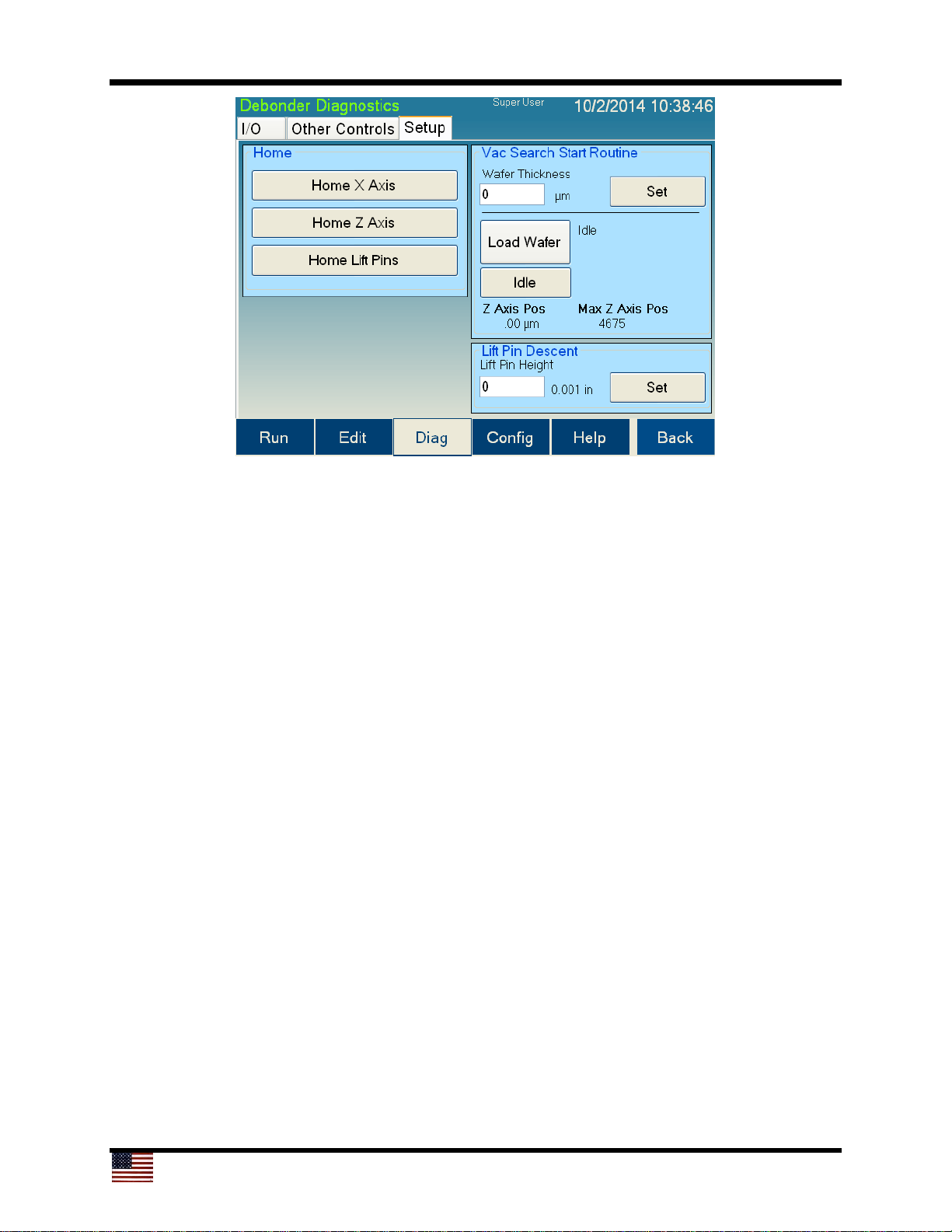
The controls and indicators found on the Setup tab of the Debonder Diagnostics screen
are listed below:
1. Home X Axis button: Homes the lower platen on the slide. The lower platen will
move away from the upper platen position until it finds the home position. Pressing
this button will move the slide to the home sensor at a high speed. Once the home
sensor detects the bottom platen, the bottom platen will move off the sensor and
then back onto the sensor at a very slow speed.
2. Home Z Axis button: Homes the lower platen lift. The lower platen will move up to
its max position. The lower platen will then move back down until the home sensor
has been tripped.
3. Home Lift Pins button: Homes the lift pins. This will move the lift pins up and then
back down until the home sensor detects the lift pins.
4. Wafer Thickness field and Set button: Field for entering the thickness of the wafer
being used for the Vacuum Search Start Routine; pressing set will store the number
5. Load Wafer/Set Start Search: Pressing the Load Wafer button will raise the lift pins
so that the wafer can be loaded. A prompt will appear when the wafer can be safely
loaded. Once the lift pins are raised fully, the Load Wafer button will change to Set
Start Search. Pressing the Set Start Search button will turn on the lower platen
vacuum and lower lift pins. Once vacuum has been achieved, the lower platen will
move to the press position and then move up slowly searching for vacuum on the
upper platen. When vacuum is achieved on the upper platen, the z-axis position is
recorded. The lower platen will move down, move to the home position, and raise
the lift pins. The Vacuum Search Start Routine is then complete.
Page 28
28
1
2
3
4
5
6
7
8
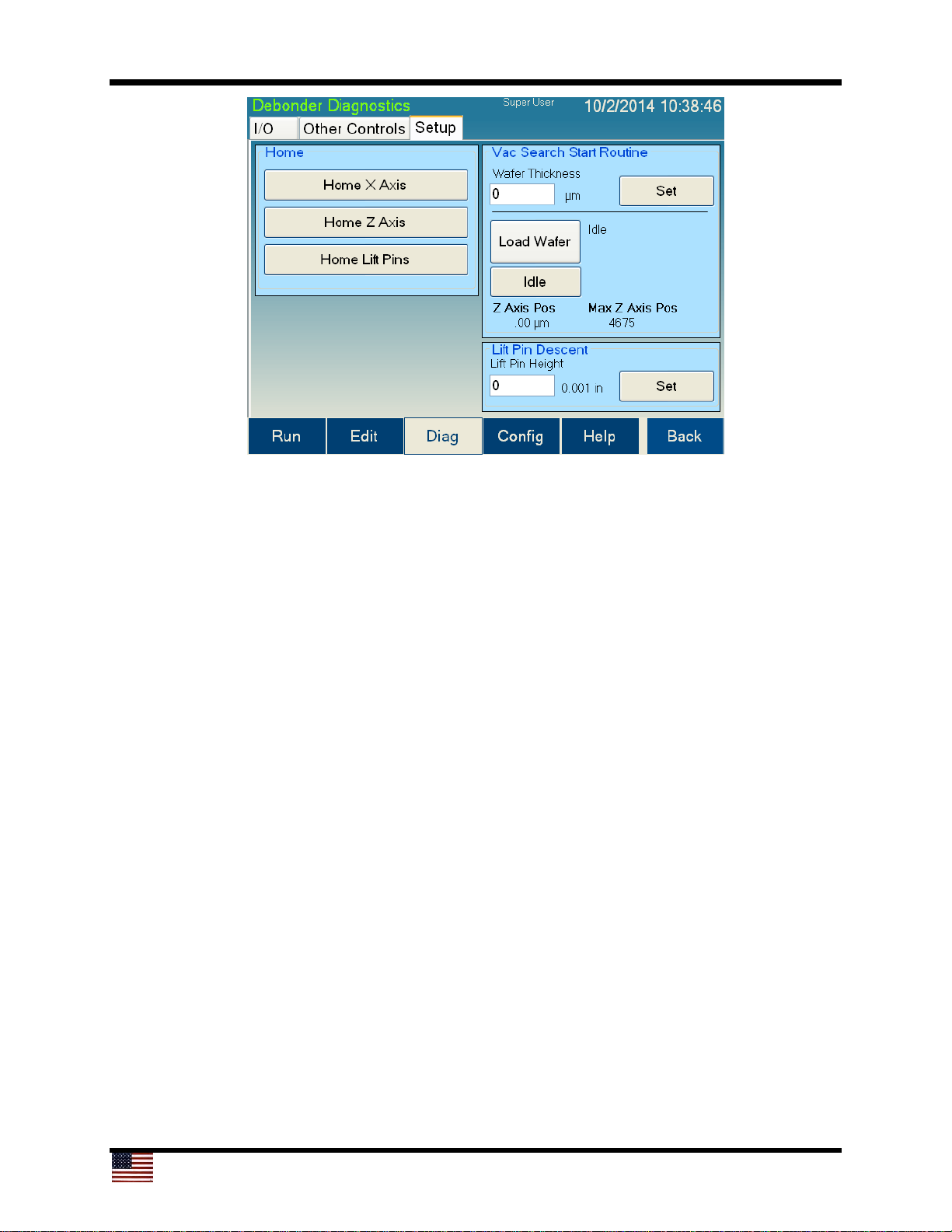
6. Idle/Abort button: This button is gray and displays Idle when the Vacuum Search
Start Routine is not active. When the Vacuum Search Start Routine is run, the
button will turn red and display Abort. Pressing this button will abort the routine
and return the lower platen to the home position.
7. Vacuum Start Search Status Display: Displays the current z-axis position and
the last recorded maximum position
8. Lift Pin Descent and Set: Field for entering a value into the Lift Pin Descent field;
pressing set will move lift pins to that height
Page 29
29
4.5 User Configuration Screen
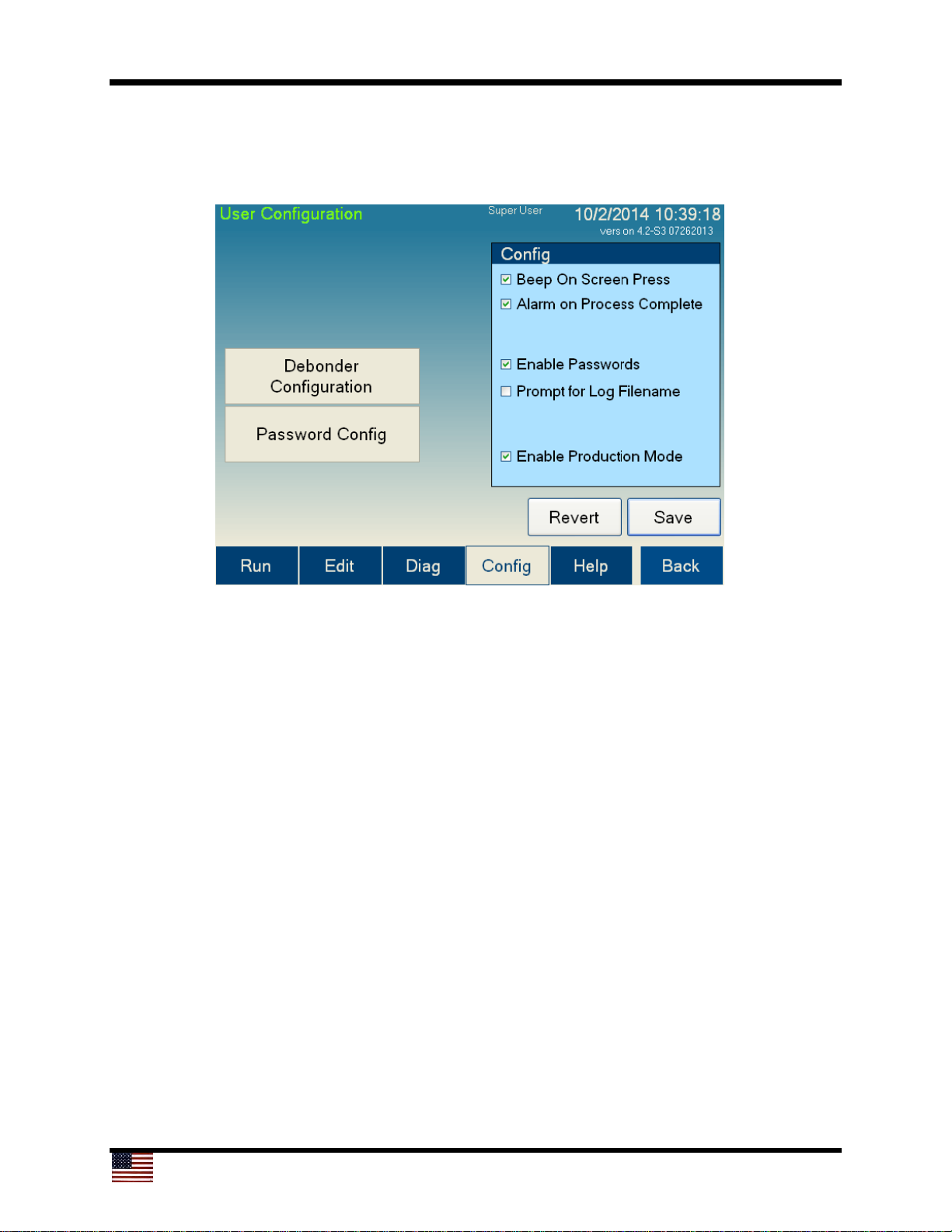
The User Configuration screen allows the user to set parameters for the Cee® 1300CSX
tool operation. Not all parameters are available to all user levels.
3
2
1
4
5
6
7
8 9
The controls and indicators found on the User Configuration screen are listed below:
1. Debonder Configuration button: Navigates to the Debonder Configuration screen
2. Password Config button: Navigates to the
Password Configuration screen
3. Beep On Screen Press: If this setting is checked, the screen will sound a slight
beep whenever a control is pressed. This feature is designed to provide feedback
while using the Cee® 1300CSX tool.
4. Alarm On Process Complete: If this setting is checked, the tool will sound an alarm
when a process is completed
5. Enable Passwords: If this setting is checked, the tool will require a password to
start. Using passwords also allows different users of different levels to access limited
portions of the Cee® 1300CSX tool’s software. If passwords are not enabled, the
Cee® 1300CSX tool automatically logs in as a Super User. For information on
logging in to the Cee® 1300CSX tool’s software, see the Run screen (section 4.1.3).
6. Prompt for Log Filename: If this box is checked, it will prompt the user to enter a
filename for the log when running a process. If the box is not checked, it will use the
date, time, and recipe name for the filename.
Page 30
30
3
2
1
4
5
6
7
8 9
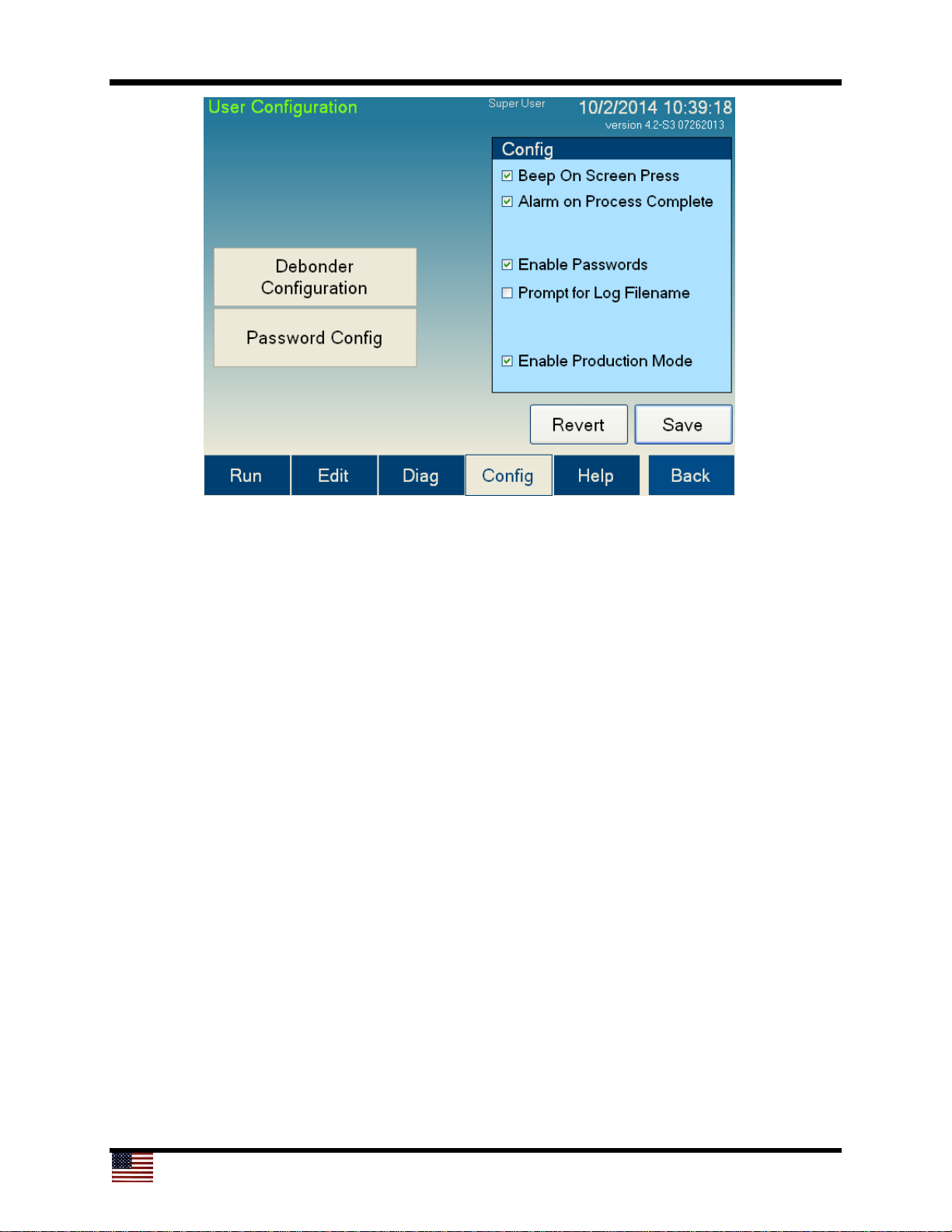
7. Enable Production Mode: Checking this box keeps the lift pins from going down
between process jobs
8. Revert button: If changes made to the settings on this screen are not desired,
pressing this button will revert back to saved settings
9. Save button: Saves all parameters on the screen
Page 31
31
4.5.1 Debonder User Configuration Screen
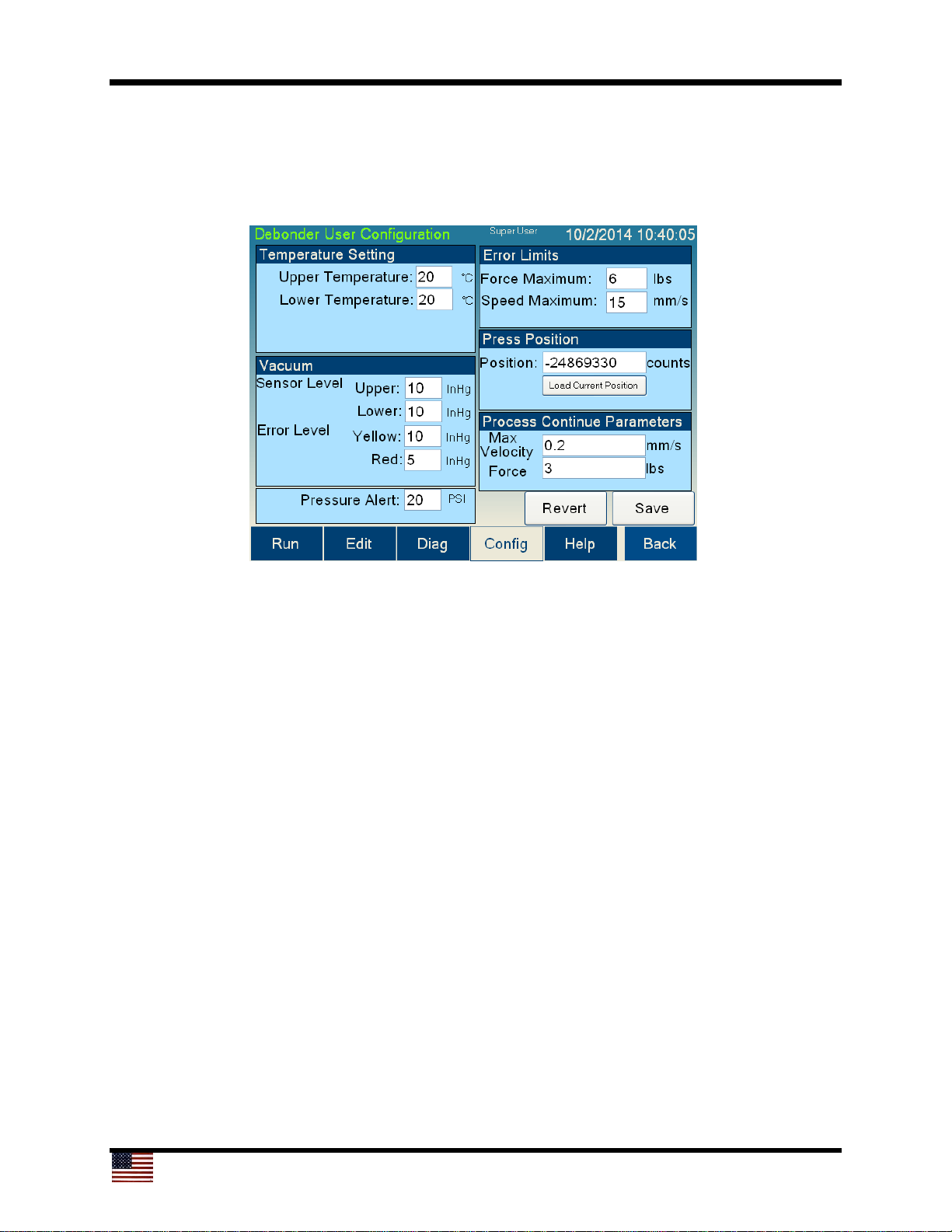
The Debonder User Configuration screen allows the user to set parameters for the
Cee® 1300CSX tool’s operation. Not all parameters are available to all user levels.
1
2
3
4
5
6
7
8
9
10
11
12
13
14 15
The controls and indicators found on the Debonder User Configuration screen are listed
below:
1. Upper Temperature setpoint: The setpoint for the upper platen. This value will be
loaded at startup.
2. Lower Temperature setpoint: The setpoint for the lower platen. This value will be
loaded at startup.
3. Vacuum sensor setpoint – Upper platen: The setpoint for vacuum level on the
upper platen. This setting is the amount of vacuum needed for the process to find
vacuum and continue the process.
4. Vacuum sensor setpoint – Lower platen: The setpoint for vacuum level on the
lower platen. This setting is the amount of vacuum needed for the process to find
vacuum and continue the process.
5. Vacuum Error level – Yellow alarm: The setpoint to trigger a warning during the
debonding process. If the vacuum on either platen falls to this level, the light tree will
show yellow but the process will continue.
6. Vacuum Error level – Red alarm: The setpoint to trigger an error during the
debonding process. If the vacuum on either platen falls to this level, the light tree will
show red and halt. A prompt will ask if the process should continue.
Page 32
32
1
2
3
4
5
6
7
8
9
10
11
12
13 14
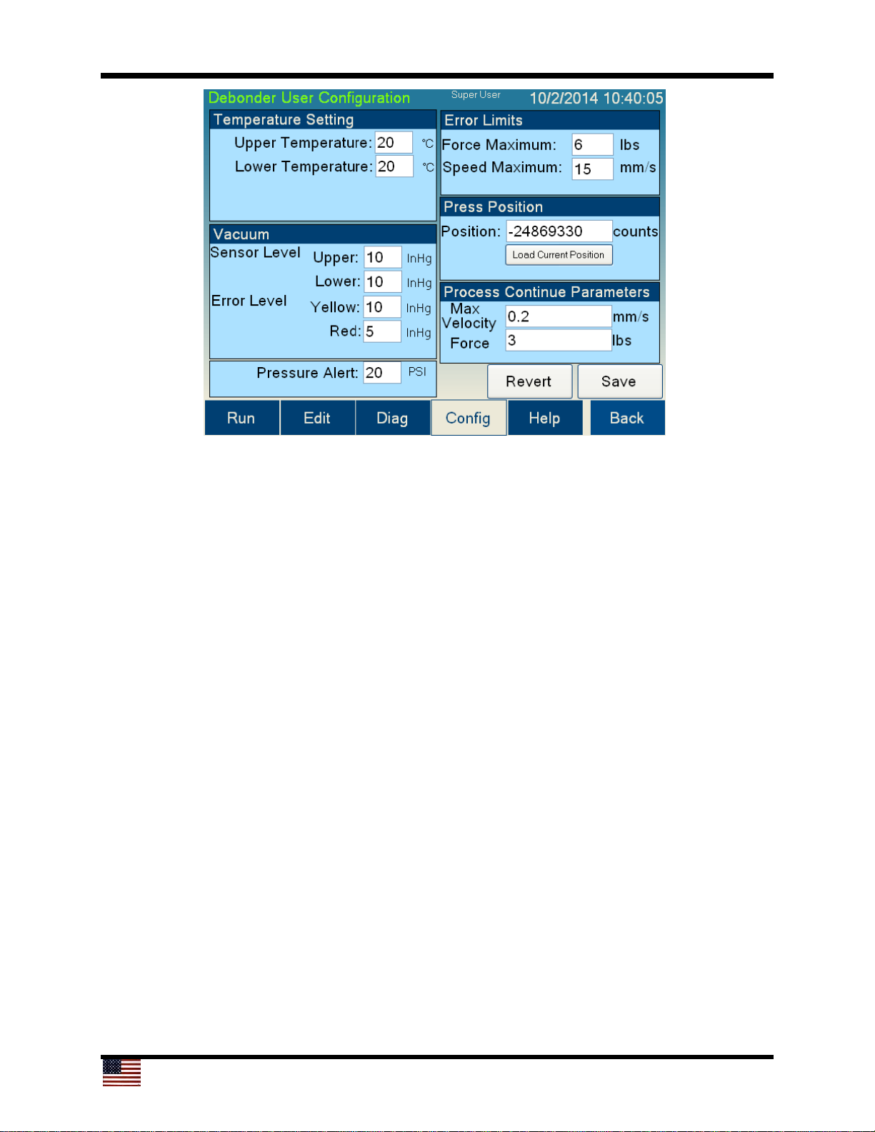
7. Pressure Alert setpoint: If the nitrogen/clean dry air (N2/CDA) pressure falls below
this setpoint, a warning message will appear
8. Force Maximum level: If the process exceeds this amount of force, the process will
halt and prompt for whether or not it should continue
9. Speed Maximum level: If the process exceeds this speed, the process will halt and
prompt for whether or not it should continue
10. Press Position: The position of the bottom platen along the slide where it will rise
and contact the upper platen; this position must be correct for the process to work
11. Load Current Position button: Loads the current position of the lower platen into
the Press Position field
12. Process Continue Parameters: If a process is aborted, the tool will allow the user
to try to continue the process. These parameters (Max Velocity, Force) will be used
instead of the ones in the recipe. This feature allows for use of safe values (slower
speed and less force) so that continued processes will have the highest chance for
success.
13. Revert button: If changes made to the settings on this screen are not desired,
pressing this button will revert back to previously saved settings
14. Save button: Saves all parameters on the screen
Page 33
33
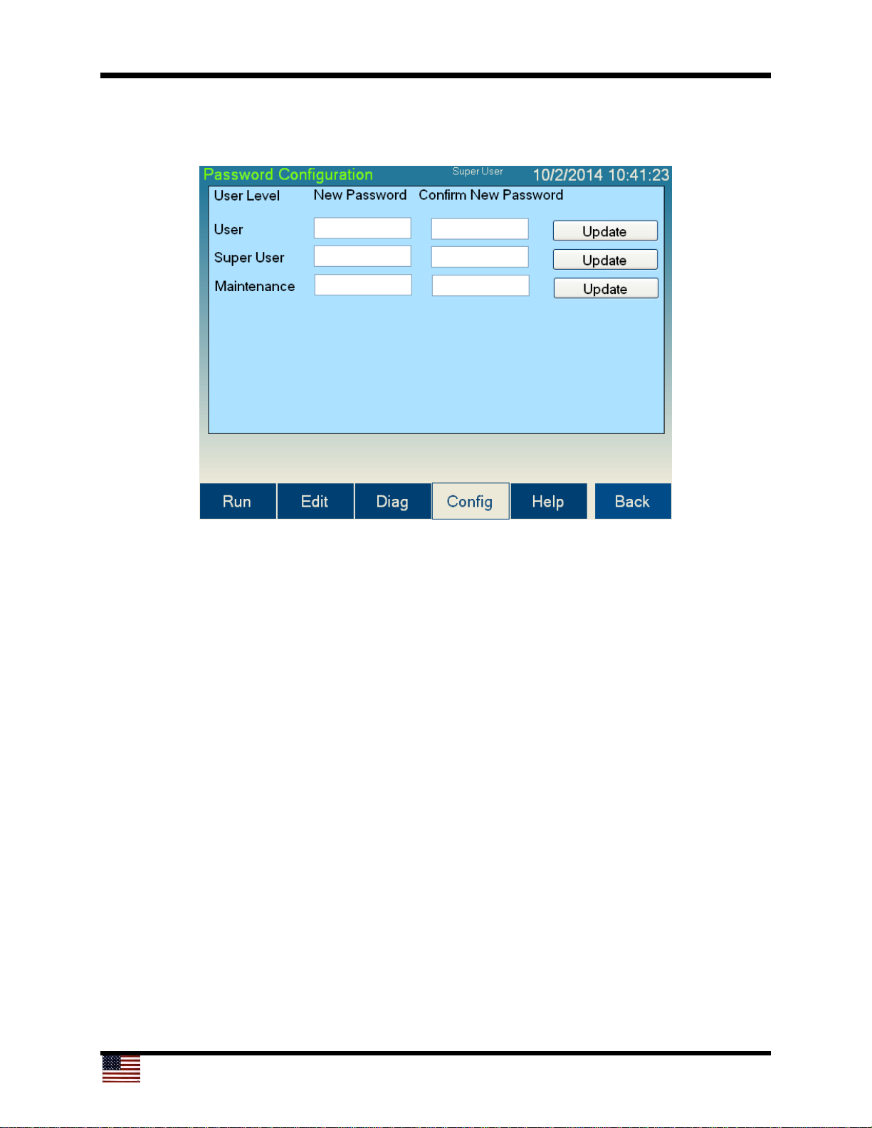
4.5.2 Password Configuration Screen
The Password Configuration screen allows the user to change passwords.
The default passwords for the Cee® 1300CSX tool are:
Super User Level: CEE
User Level: 1300CSX
Maintenance: DIAG
To change a password, press the New Password box for the desired user level, and an
on-screen keyboard will appear which allows the user to enter a new password. The onscreen keyboard will not display the password. Retype the new password in the Confirm
New Password box. To save, press Update. If the entries in the New Password box and
the Confirm New Password box match, the new password will be stored.
4.5.3 User Level Access
The level of access given to each different user level is:
Super User Level: Everything
User Level: Run screen
Maintenance: Run screen, Diagnostics screen, Configuration screen
By de-selecting the Enable Passwords option on the User Configuration screen, the
Cee® 1300CSX tool’s software will automatically log in at the Super User level.
Page 34
34
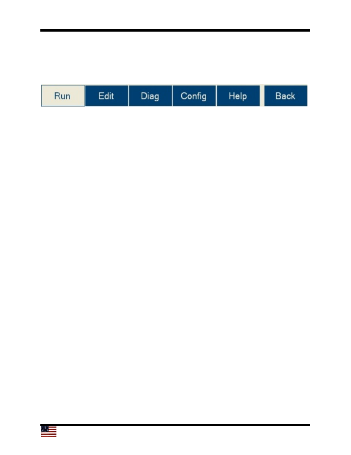
4.6 Navigation Bar
The navigation bar enables quick navigation of the Cee® 1300CSX tool’s software. The
currently selected page is highlighted in white. The buttons on the navigation bar are
listed below:
Run button: Navigates to the Run screen, which is where processes are run and
monitored on the Cee® 1300CSX tool
Edit button: Navigates to the Edit screen, which is where processes are created,
edited, and deleted on the Cee® 1300CSX tool
Diag button: Navigates to the Diagnostics screen. From here, the Cee® 1300CSX tool
can be operated manually, allowing maintenance and diagnostics to be performed.
Config button: Navigates to the Configuration screen. All the user-configurable settings
for the Cee® 1300CSX tool can be viewed or edited here.
Help button: Navigates to the Help page, which contains the User Manual
Back button: Returns to the previous screen
Windows® and Microsoft® are registered trademarks of Microsoft Corporation in the United States and other
countries.
 Loading...