

Page 1
CEDRAT TECHNOLOGIES www.cedrat-technologies.com
59, Chemin du vieux chêne - Inovallée [email protected]
F-38246 MEYLAN Cedex Phone: +33.(0)4.56.58.04.00
FRANCE Fax: +33.(0)4.56.58.04.01
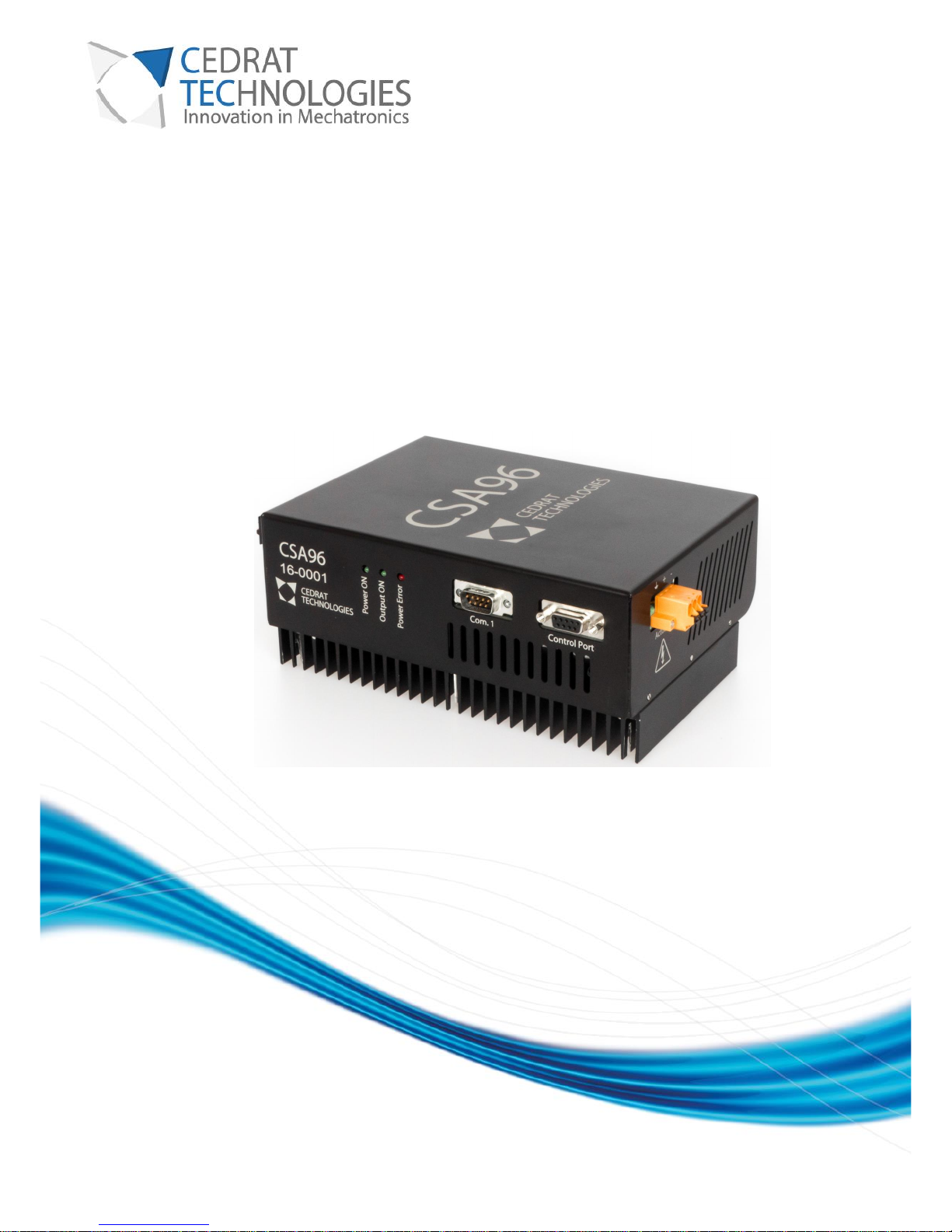
CSA96
CURRENT SWITCHING AMPLIFIER
Version: 1.0.8
Date: 18/12/2017
Page 2
CURRENT SWITCHING AMPLIFIER
2
CEDRAT TECHNOLOGIES Current Switching Amplifier 18/12/2017
CAUTION: READ BEFORE USE
For safety purposes these instructions must be read before use of this product.
Only qualified personnel should work on or around this equipment and only after becoming
thoroughly familiar with all warnings, safety notices, and procedures contained herein.
The successful and safe operation of this equipment is dependent on proper handling, installation
and operation.
A "qualified person" is one who is familiar with the installation, construction and operation of the
equipment and the hazards involved. In addition, he/she has the following qualifications :
• is trained and authorized to energize, de-energize, clean, and ground equipment in
accordance with established practices,
• is trained in the proper care and use of protective equipment in accordance with
established safety practices,
• is trained in the soldering process and wiring of connectors,
• is familiar with the EMC and safety requirements.
To comply with the safety and EMC regulation, the user must install and configure the product
correctly. Qualified person, who is familiar with the EMC and safety requirements, must install the
product and is responsible for ensuring that the end product complies with the relevant laws in
the country, where it is going to be used. Special care should be taken regarding electrical safety
since the product is capable of providing high voltages.
Page 3
CURRENT SWITCHING AMPLIFIER
3
CEDRAT TECHNOLOGIES Current Switching Amplifier 18/12/2017
Table of contents
1. DESCRIPTION ........................................... 5
2. MAIN FEATURES ......................................... 5
3. INTENDED USE .......................................... 6
4. ELECTRICAL SAFETY INFORMATION ........................... 7
5. INFORMATION ON DISPOSAL FOR USERS OF WASTE ELECTRICAL &
ELECTRONIC EQUIPMENT (PRIVATE HOUSEHOLDS) ................. 9
6. DISCLAIMER ........................................... 10
7. INTERFACES ........................................... 11
7.1. FRONT SIDE ............................................... 11
7.2. CONTROL PORT ............................................ 11
7.3. COMMUNICATION PORT ....................................... 13
7.3.1. Command list .................................................................. 13
7.4. OPTOCOUPLERS ............................................ 14
7.5. TOP SIDE – POWER SUPPLY TERMINAL ............................ 15
7.6. BOTTOM SIDE – ACTUATOR TERMINALS ........................... 17
7.7. WIRING .................................................. 18
7.7.1. CSA96 Internal Supply version ....................................................... 18
7.7.2. CSA96 External Supply version ....................................................... 19
7.7.3. EMC considerations .............................................................. 19
8. THEORY OF OPERATION ................................... 20
8.1. PRINCIPLE ................................................ 20
8.2. EFFICIENCY AND COOLING ..................................... 20
8.3. LIMITATIONS AND PROTECTIONS ................................ 21
Page 4
CURRENT SWITCHING AMPLIFIER
4
CEDRAT TECHNOLOGIES Current Switching Amplifier 18/12/2017
8.3.1. Current limitation ................................................................ 21
8.3.2. Energy recovery ................................................................. 21
8.3.3. Rheostatic braking ............................................................... 22
8.3.4. Buffer capacitor extension .......................................................... 23
8.3.5. Minimum output inductance value .................................................... 24
8.3.6. Protections .................................................................... 24
9. MAIN VOLTAGE CONNEXIONS ............................... 24
9.1. CIRCUIT BREAKER ........................................... 24
10. OPERATING INSTRUCTION FOR THE AMPLIFIER .................. 25
10.1. GENERAL INSTRUCTIONS ...................................... 25
TROUBLESHOOTING ......................................... 26
WARRANTY CONDITIONS AND EXCEPTIONS ........................ 27
INSPECTION UPON RECEIPT ................................... 28
AFTER-SALES SERVICE ....................................... 29
APPENDIX 1 : TROUBLESHOOTING FORM .......................... 30
Page 5
CURRENT SWITCHING AMPLIFIER
5
CEDRAT TECHNOLOGIES Current Switching Amplifier 18/12/2017
1. DESCRIPTION
The CSA96 consists in a powerful and compact current switching amplifier designed to drive magnetic
actuators. It includes a power supply and as options, the possibility to connect an external power supply,
increasing output voltage and power capability, and a control board dedicated to advanced control of
actuators (position control, velocity control, etc.).
The external dimensions of the CSA96 are the following:
CSA96
Width : 140 mm
Length : 210 mm
Height : 59 mm
In case of optional controller, the height is 71mm.
The bottom plate is also a thermal interface used to dissipate the heat of the converter. The packaging also
features side openings for air circulation in order to enhance the heat dissipation.
2. MAIN FEATURES
The CSA96 is available in two versions, the first one features a powerful internal AC/DC converter which allows
to connect directly the amplifier on mains. The second permits to use a DC input voltage source.
CSA96
Included Power Supply
External Power Supply
Option
IS
ES
Voltage
96V
200V
Current
20A
20A
Apparent Power
1920VA
4000VA
Active Power
<660W
4kW max
Efficiency typ. (amplifier)
98%
98%
Efficiency typ. (supply)
93.5%
-
Switching frequency
50kHz
50kHz
The CSA96-IS is characterized by an integrated power supply 110/230Vac to 96V – 660W.
Page 6
CURRENT SWITCHING AMPLIFIER
6
CEDRAT TECHNOLOGIES Current Switching Amplifier 18/12/2017
Fully isolated from ground. (4.2kV between primary and secondary)
Active Power Factor Correction (meets EN 61000-3-2).
High apparent and active power output.
Compact size.
3. INTENDED USE
The CSA96 is intended to be used in electrical cabinets.
Page 7
CURRENT SWITCHING AMPLIFIER
7
CEDRAT TECHNOLOGIES Current Switching Amplifier 18/12/2017
4. ELECTRICAL SAFETY INFORMATION
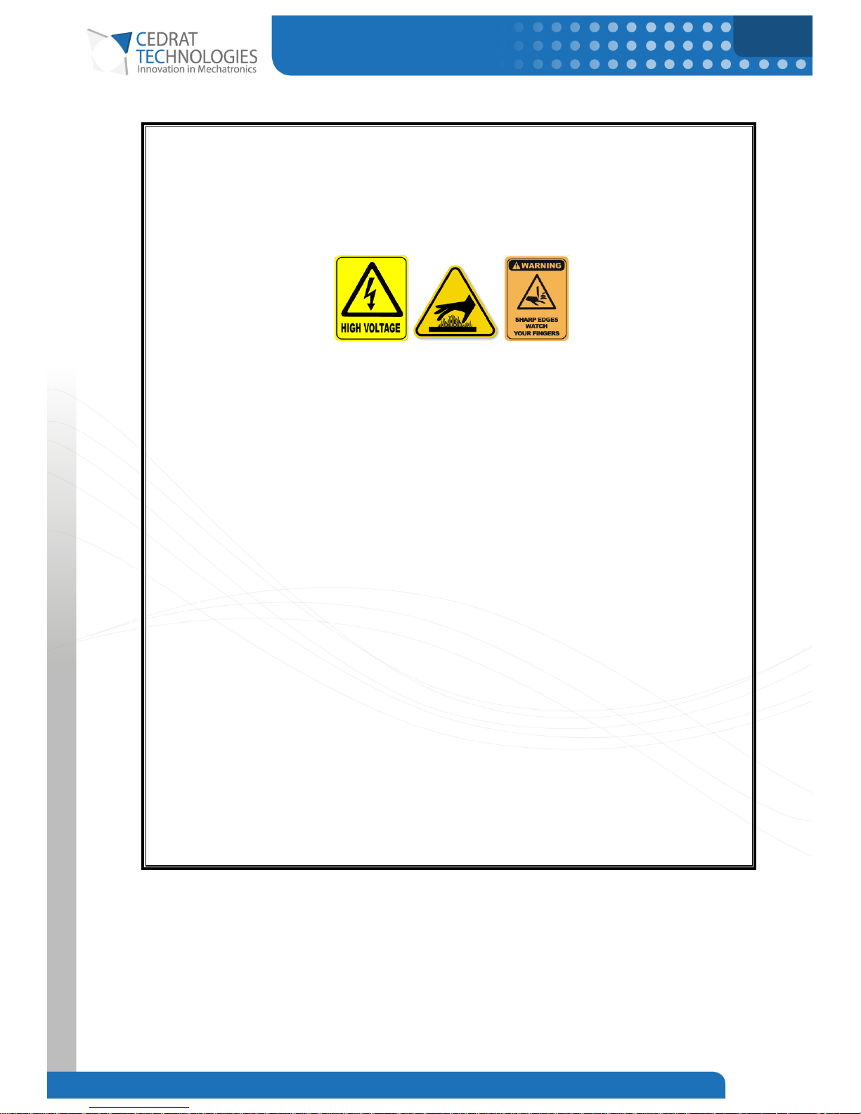
The following safety symbols are used in this manual.
Warning
For you own safety and for your system security, be sure to carefully respect that
information.
Danger
This symbol alerts you about an electrical hazard.
Failure to follow these instructions will result in death or serious injury.
In order to achieve a safe operation of the CSA96 driver, some safety information must be given. This
information is intended to protect the user and the product, and allows safe operating of the product.
The product includes two earth connections, one is intended to connect the driver to the earth, and the other
is to connect the actuator to the earth.
Warning
Since the package is fully metallic, you need to connect the driver to the earth for
the user to be safe.
Page 8
CURRENT SWITCHING AMPLIFIER
8
CEDRAT TECHNOLOGIES Current Switching Amplifier 18/12/2017
Only qualified personnel can install and use the CSA96. Only Cedrat Technologies can open or repair the
CSA96.
Danger
Do not open the product during or after use, lethal voltages may be present even
after the product has been turned off.
Do not short the DC voltage bus or the braking resistor terminals.
Do no touch unshielded components or terminals with voltage present.
Avoid all contact with the product when powered on. If the user need to operate on
the product follow the following guideline :
- Turn off the product and disconnect the power source.
- Wait 1 min to allow the DC bus to discharge.
- Measure the voltage on the DC bus with a properly rated voltmeter to verify
that the voltage is below 42Vdc.
Danger
This device produces hazardous potentials and should be used by suitably qualified
personnel. Do not operate the device when there are exposed conductors. Parts of
the circuit may store charge so precautions must also be taken when the device is
not powered.
Page 9
CURRENT SWITCHING AMPLIFIER
9
CEDRAT TECHNOLOGIES Current Switching Amplifier 18/12/2017
Danger
Before powering on, ensure that enable input is turned off to help prevent an
accidental startup.
5. INFORMATION ON DISPOSAL FOR USERS OF
WASTE ELECTRICAL & ELECTRONIC
EQUIPMENT (PRIVATE HOUSEHOLDS)
This symbol on the product(s) and / or accompanying documents means that used electrical and
electronic products should not be mixed with general household waste. For proper treatment, recovery and
recycling, please take this product(s) to designated collection points where it will be accepted free of charge.
Alternatively, in some countries you may be able to return your products to your local retailer upon purchase
of an equivalent new product.
Disposing of this product correctly will help save valuable resources and prevent any potential negative effects
on human health and the environment, which could otherwise arise from inappropriate waste handling.
Please contact your local authority for further details of your nearest designated collection point.
Penalties may be applicable for incorrect disposal of this waste, in accordance with you national legislation.
For business users in the European Union:
If you wish to discard electrical and electronic equipment, please contact your dealer or supplier for further
information.
Information on Disposal in other Countries outside the European Union
This symbol is only valid in the European Union. If you wish to discard this product please contact your local
authorities or dealer and ask for the correct method of disposal.
Page 10
CURRENT SWITCHING AMPLIFIER
10
CEDRAT TECHNOLOGIES Current Switching Amplifier 18/12/2017
6. DISCLAIMER
All product, product specifications and data are subject to change without notice to improve reliability,
function or design or otherwise.
Cedrat Technologies makes no warranty, representation or guarantee regarding the suitability of the products
for any particular purpose or the continuing production of any product.
Except as expressly indicated in writing, Cedrat Technologies products are not designed for use in medical,
life-saving, or life-sustaining applications or for any other application in which the failure of the Cedrat
Technologies product could result in personal injury or death.
Page 11
CURRENT SWITCHING AMPLIFIER
11
CEDRAT TECHNOLOGIES Current Switching Amplifier 18/12/2017
7. INTERFACES
7.1. FRONT SIDE
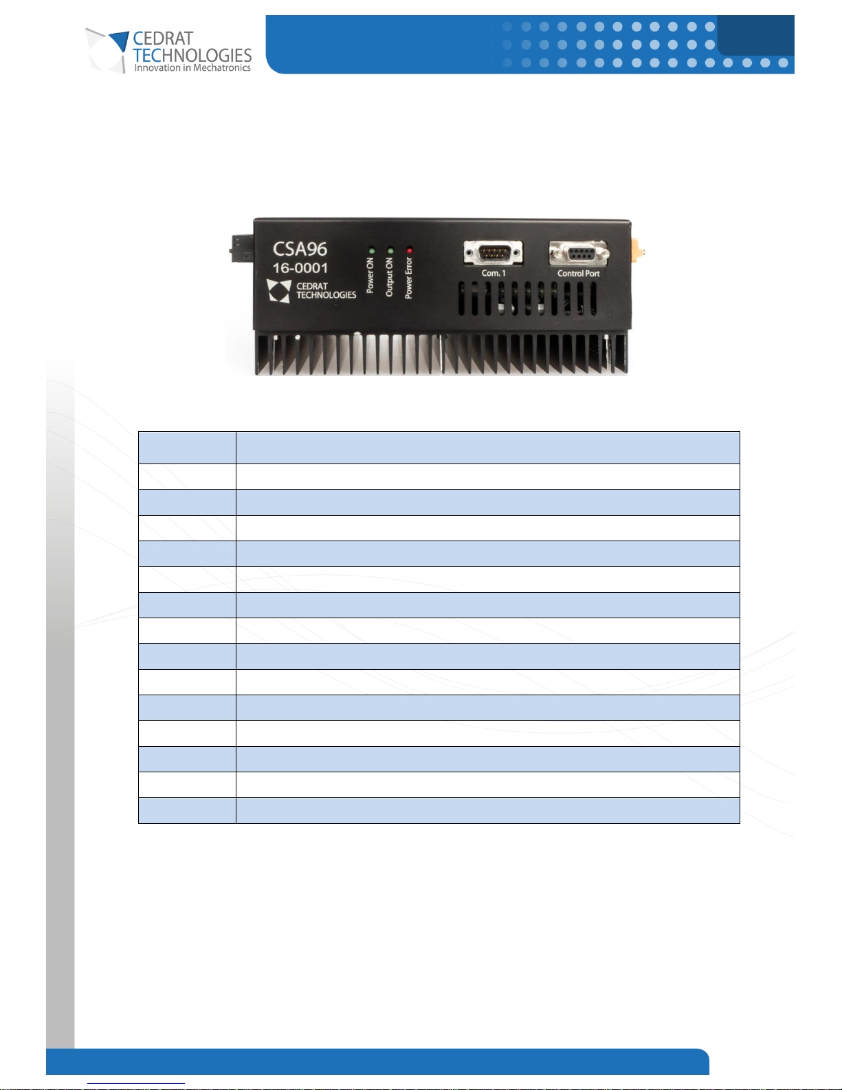
Figure 1. Front side of the CSA96 with optional controller
Reference
Designation
1st module
Current Switching Amplifier - CSA96
Power ON
LED (green) – This diode lights when the product is connected to a power source.
Output ON
LED (green) – This diode lights when the product is enabled.
Power Error
LED (red) – This diode lights when the product is in fault state.
COM1
Connector SUBD9-M – This port is reserved.
Control Port
Connector SUBD9-F – Control Port.
2nd module
Controller Board (TBD)
Analog I/O
TBD
CAN/Profibus
Ctrl Error
LED (red) – This diode lights when the controller board is in fault state.
Ethernet
USB
USB port.
Digital I/O
TBD
Table 1. Electrical interface assignments.
7.2. CONTROL PORT
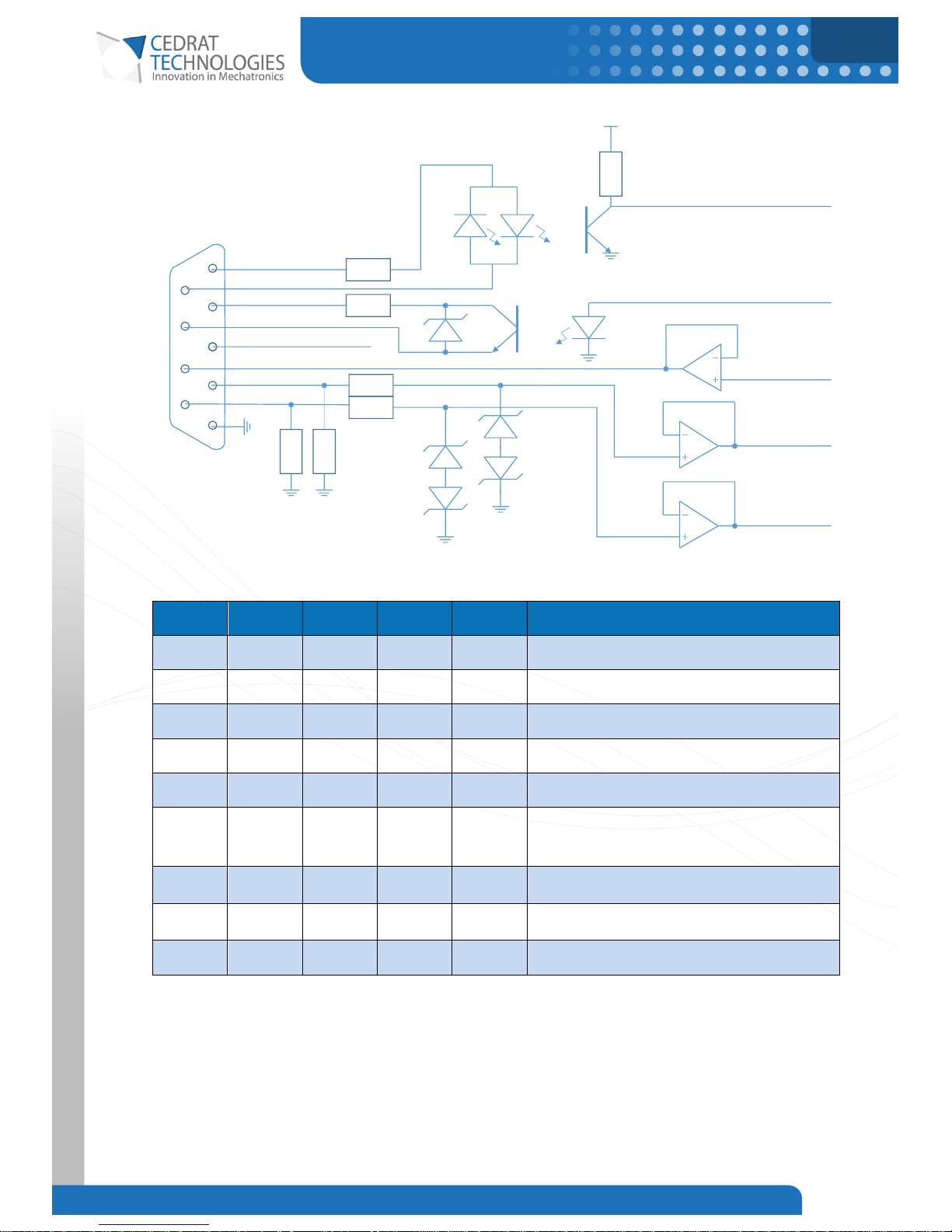
The User Port permits to control the amplifier with a differential analog signal (±10V), to monitor the output
current and to enable the amplifier.
Page 12
CURRENT SWITCHING AMPLIFIER
12
CEDRAT TECHNOLOGIES Current Switching Amplifier 18/12/2017
Figure 2. Internal schematic of the Control Port.
Pin
Signal
I/O
Isolation
Type
Function
1
Enable+
Input
Yes
Digital
Positive (Anode) of the enable optocoupler.
6
Enable-
Input
Yes
Digital
Negative (Cathode) of the enable optocoupler.
2
Fault+
Output
Yes
Digital
Collector of the fault optocoupler.
7
Fault-
Output
Yes
Digital
Emitter of the fault optocoupler.
3
GND No
8
I
meas
Output
No
Analog
Output current sensing (offset = 2.5V,
sensitivity : 56mV/A)
4
In+
Input
No
Analog
Positive order input. (±10V)
9
In-
Input
No
Analog
Negative order input. (±10V)
5
GND No
Table 2. Control port pin assignements.
Note: Isolated signals can withstand 200Vrms from ground. Non-isolated signals are referenced to GND.
The order is differential to increase immunity against common mode noise.
1
2
3
4
5
6
7
8
9
330R
33R
15V
Fault
Enable
Enable+
EnableFault+
Fault-
Imes
Imes
10k
5V
10k
10k
10k
10k
In+
In-
In+
In-
15V
15V
User Port
Reserved (Do Not Connect)
GND
Page 13
CURRENT SWITCHING AMPLIFIER
13
CEDRAT TECHNOLOGIES Current Switching Amplifier 18/12/2017
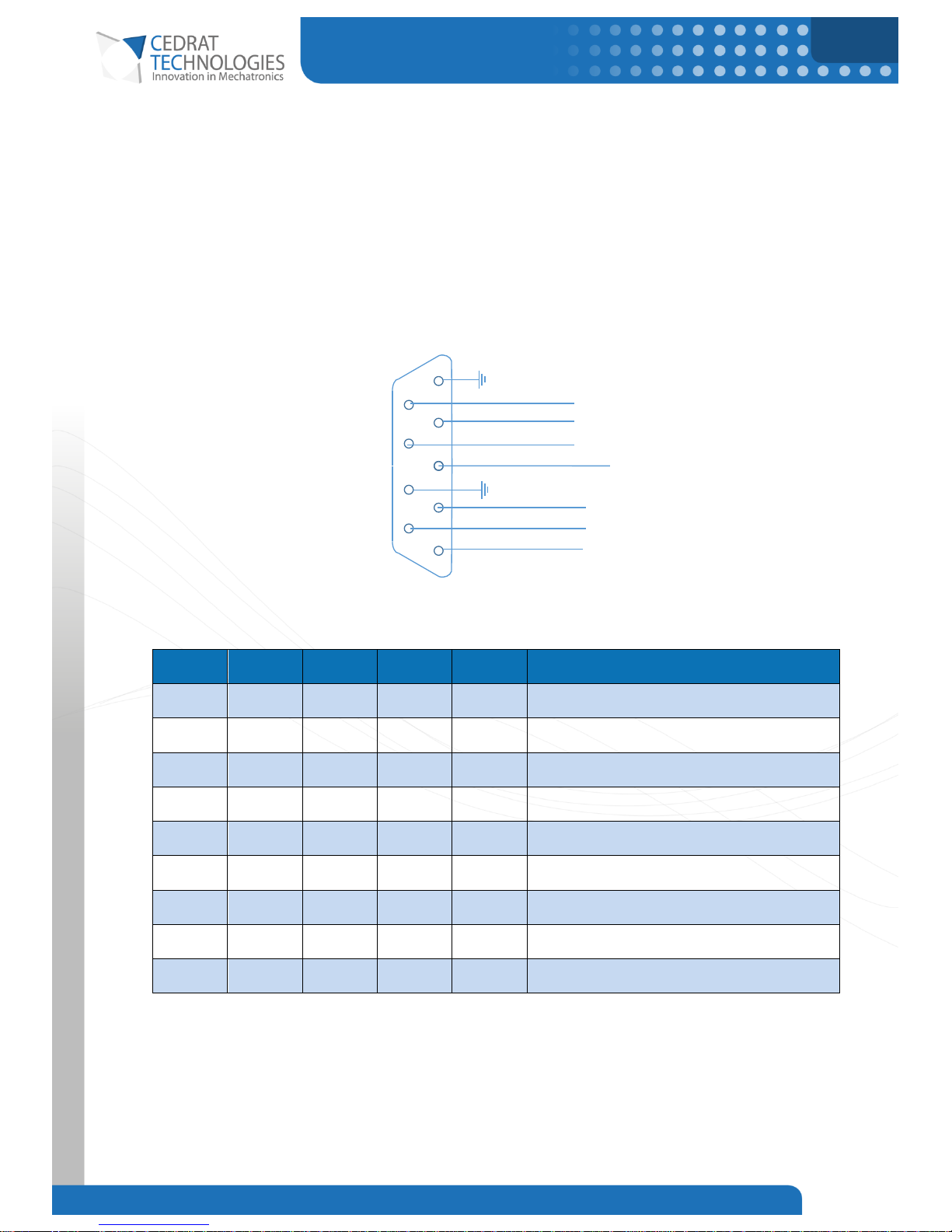
7.3. COMMUNICATION PORT
In order to drive different actuators, the PI parameters of the internal current control may need tuning. This
can be done on a PC using the TTL serial communication link and a FTDI TTL to USB converter (part number:
TTL-232R-5V-WE) through the Com. 1 port.
RX, TX and CTS can be used to communicate with the amplifier in order to tune the PI controller parameters.
Figure 3. Internal schematic of the Com. 1 Port
Pin
Signal
I/O
Isolation
Type
Function
5
GND
9
RX
Input
No
Digital
Receive signal - Serial communication
4
TX
Output
No
Digital
Transmit signal - Serial communication
8
CTS
Output
No
Digital
Clear To Send - Serial communication
3
Reserved
Do not connect
7
GND
2
OT
Output
No
Digital
OverTemp fault
6
OV
Output
No
Digital
OverVoltage/UnderVoltage fault
1
OC
Output
No
Digital
OverCurrent fault
All digital inputs/outputs are TTL 5V signals.
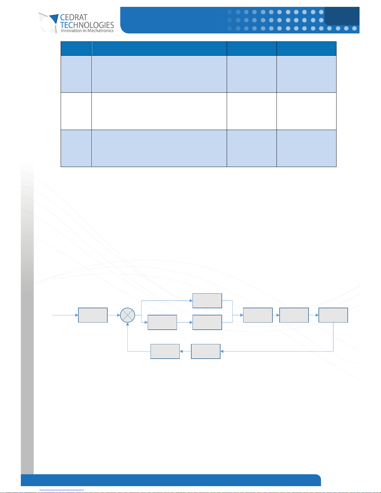
7.3.1.Command list
The list of available digital commands for the CSA96 is in the following table:
5
4
3
1
9
8
7
6
GND
RX
TX
CTS
GND
OverTemp
OverVoltage
Com. 1
Reserved (Do Not Connect)
2
Overcurrent
Page 14
CURRENT SWITCHING AMPLIFIER
14
CEDRAT TECHNOLOGIES Current Switching Amplifier 18/12/2017
Character
Description
Parameter range
Example
‘A’
This command prints the current parameters.
0-255
Value is a ‘don’t
care’
‘A1E’
‘P’
Sets the proportional term P of the PI controller
0-235
‘P150E’
Sets the proportional
gain to 150.
‘I’
Sets the integral term I of the PI controller
8310-96700
‘I13300E’
Sets the integral gain
to 13300.
P and I command are made to be intelligible and proportional gains to usual Kp and Ki gain. Internally, those
values are 8bits values, some differences may appears between entered values and effective values.
The internal current loop is presented in the Figure 4.
When a parameter of the CSA96 is modified, the new parameter value is automatically saved in a non-volatile
memory. The parameters of the CSA96 are automatically recalled on startup, so that the user does not have
to reconfigure the board on every power-up.
Since those commands write the memory, their execution time is longer.
Figure 4. Internal current loop diagram.
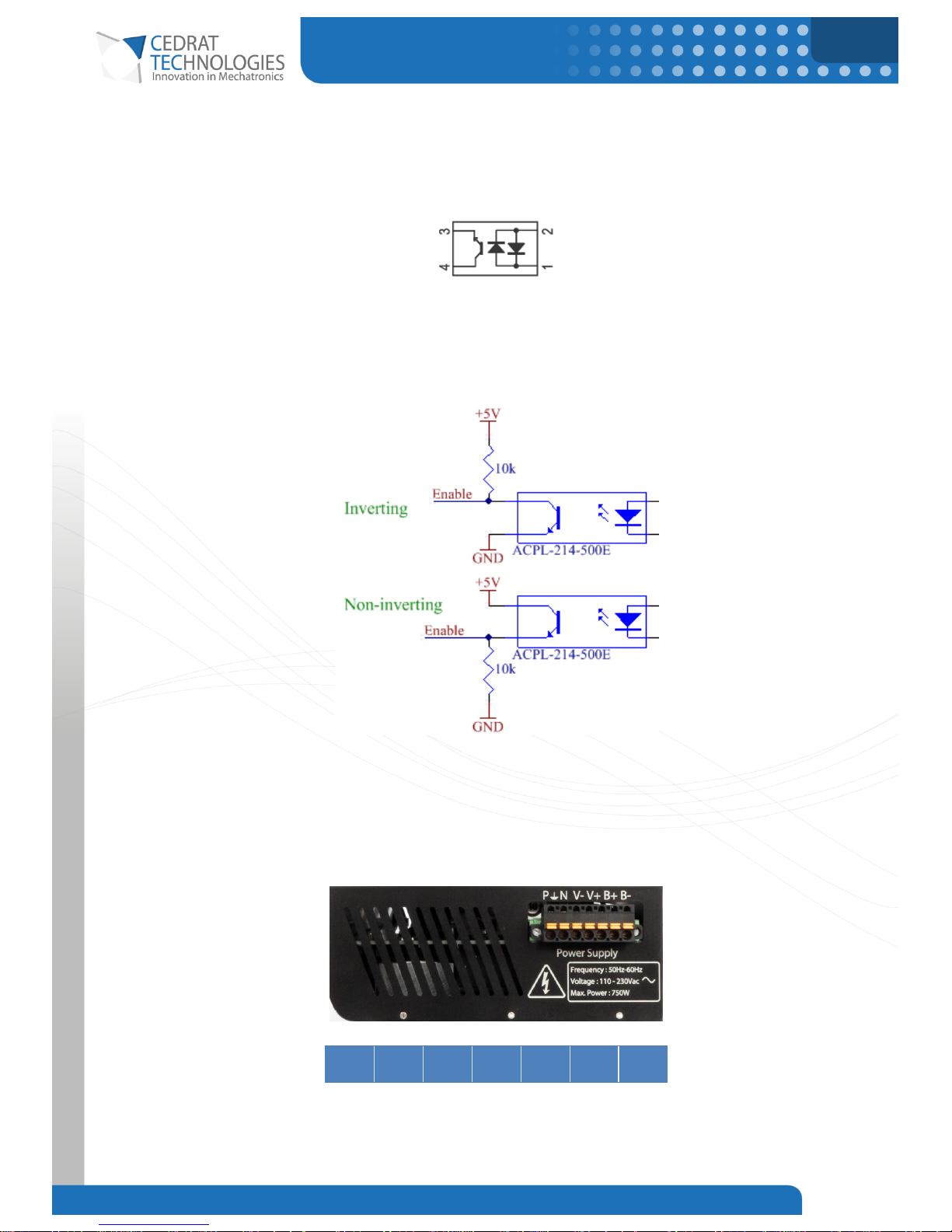
7.4. OPTOCOUPLERS
The series resistance of the enable optocoupler (Figure 2) has been set to allow enabling the amplifier with a
digital voltage of 5V without adding any component. In this case, the current needed is 12mA. A digital
command with a higher voltage is possible but needs the use of a higher series resistance which has to be
P
0…235
I
8.3k…93k
ActVbus/6.2
0.056A/V
Ampli
Corrector
Gain
Delay
~1/50kHz
120kHz
0.112
Current
I
47
Order
Page 15
CURRENT SWITCHING AMPLIFIER
15
CEDRAT TECHNOLOGIES Current Switching Amplifier 18/12/2017
implemented externally. The optocoupler is AC-input and contains actually two light emitting diodes
connected inversely parallel and are optically coupled to a phototransistor (Figure 5). These diodes can also
be directly driven by current. The recommended current value is 10mA. The internal resistance is 330R as
shown on Figure 2.
Figure 5. Internal diagram of the ACPL-214 optocoupler with its two diodes.
The breakdown voltage of the transistor side is 80V (collector-emitter), the emitter-collector breakdown
voltage is 7V.
Figure 6. Inverting and non-inverting proposed connection at the user side.
7.5. TOP SIDE – POWER SUPPLY TERMINAL
Figure 7. 16XXX Side panel.
P E N
Vb-
Vb+
B+
B-
Table 3. Pin out of the power supply connector. (16XXX version)
Page 16
CURRENT SWITCHING AMPLIFIER
16
CEDRAT TECHNOLOGIES Current Switching Amplifier 18/12/2017
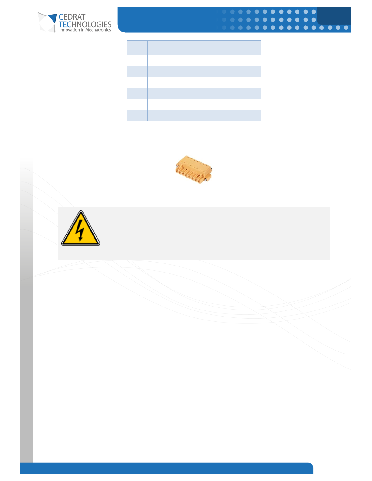
P
Line AC input (110/230Vac)
E
Earth
N
Neutral AC input (110/230Vac)
V-
Negative voltage bus
V+
Positive voltage bus
B-
Braking potential
B+
Braking potential (internally tied to V+)
Table 4. Full description of the power supply connector.
A recommended mating connector is the BLF 5.08HC/07/180F (Weidmueller):
Figure 8. BLF 5.08HC/03/180F
Danger
This connector supports potential lethal voltage. Never connect/disconnect one of
these pins while the power source is on.
Page 17
CURRENT SWITCHING AMPLIFIER
17
CEDRAT TECHNOLOGIES Current Switching Amplifier 18/12/2017
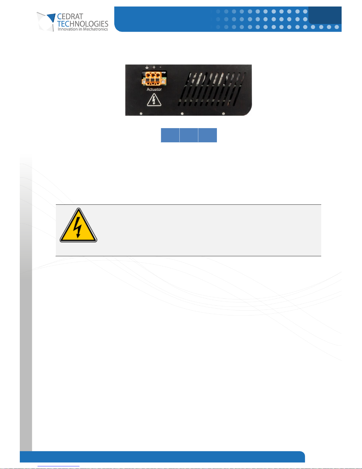
7.6. BOTTOM SIDE – ACTUATOR TERMINALS
Figure 9. Top left hand corner of the bottom side of the CSA96.
E + -
Table 5. Pin out of the actuator (output) connector.
Connect the magnetic actuator on this terminal. Do not connect any capacitance or capacitive actuator on
this terminal.
A recommended mating connector is the BLF 5.08HC/03/180F (Weidmueller).
Danger
This connector supports potential lethal voltage. Never connect/disconnect one of
these pins while the power source is on.
Page 18
CURRENT SWITCHING AMPLIFIER
18
CEDRAT TECHNOLOGIES Current Switching Amplifier 18/12/2017
7.7. WIRING
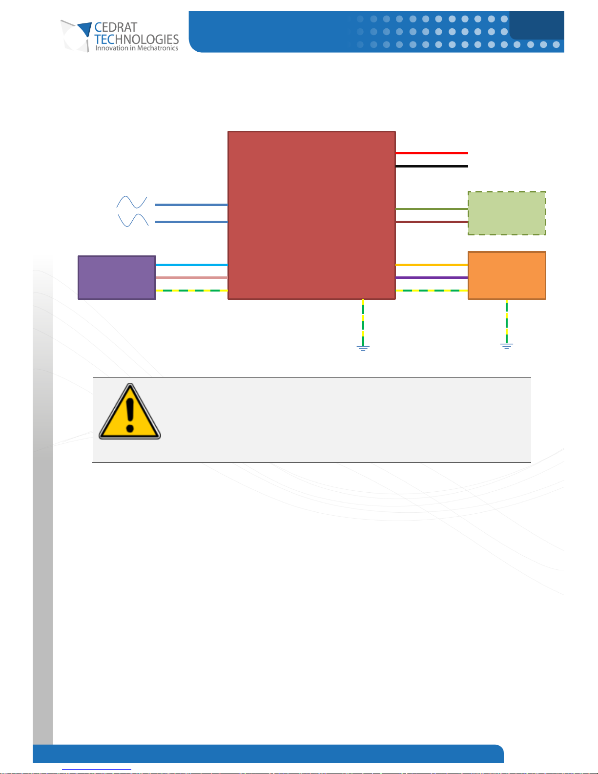
7.7.1.CSA96 Internal Supply version
Figure 10. Wiring of the internal power supply version of the CSA96
Warning
A circuit breaker must be added to connect/disconnect the driver from main
voltage.
CSA96
Amplifier
(Internal Supply version)
In+
In-
Differential Inputs ±5V
Neutral
Phase
Earth Earth
Vo+
Vo-
B+
B-
Braking
Rheostat
Mains
V+
V-
Actuator
Protective
Earth
Protective
Earth
Page 19
CURRENT SWITCHING AMPLIFIER
19
CEDRAT TECHNOLOGIES Current Switching Amplifier 18/12/2017
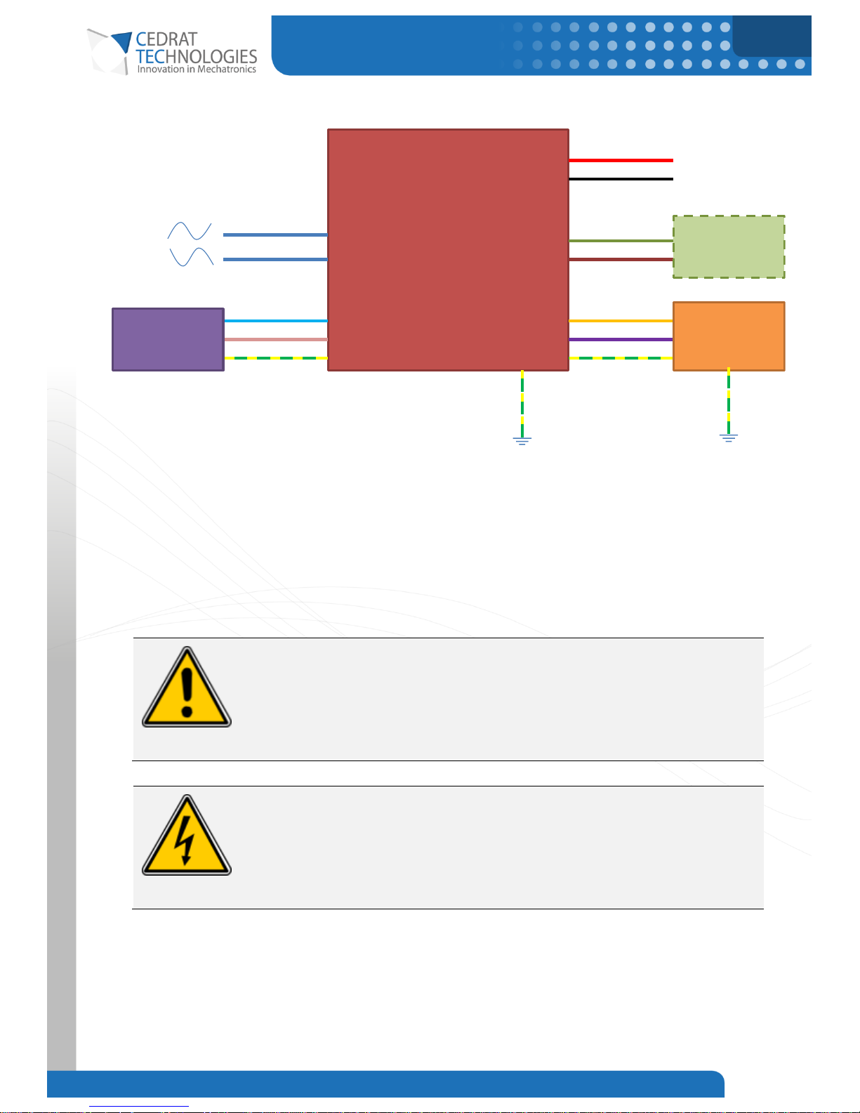
7.7.2.CSA96 External Supply version
Figure 11. Wiring of the external power supply version of the CSA96
The DC power supply shall be connected to Phase and Neutral to supply the internal, auxiliary power supply
of the product. It must include current limitation in order to limit the inrush current in the internal capacitors.
There is no polarity since a full wave rectifier is used inside. The minimum DC voltage is 40Vdc and the
maximum is 190Vdc.
The recommended wire gauge for the power cable is 14AWG with a nominal section of 2.1mm².
Warning
It is strictly forbidden to connect the electrical output channels of several CSA96 in
parallel.
Danger
This product contains components with lethal voltage, it is strictly forbidden for the
user to remove the boards from the case and to disconnect the load when
electrically powered.
7.7.3.EMC considerations
It is highly recommended to use shielded cable to connect the actuator to the CSA96 and for the Control Port
connection. Keep all wires and cables as short as possible.
CSA96
Amplifier
(External Supply version)
In+
In-
Differential Inputs ±5V
Neutral
Phase
Earth Earth
Vo+
Vo-
Actuator
B+
B-
Braking
Rheostat
V+
V-
DC Power
Supply
Protective
Earth
Protective
Earth
Page 20
CURRENT SWITCHING AMPLIFIER
20
CEDRAT TECHNOLOGIES Current Switching Amplifier 18/12/2017
8. THEORY OF OPERATION
8.1. PRINCIPLE
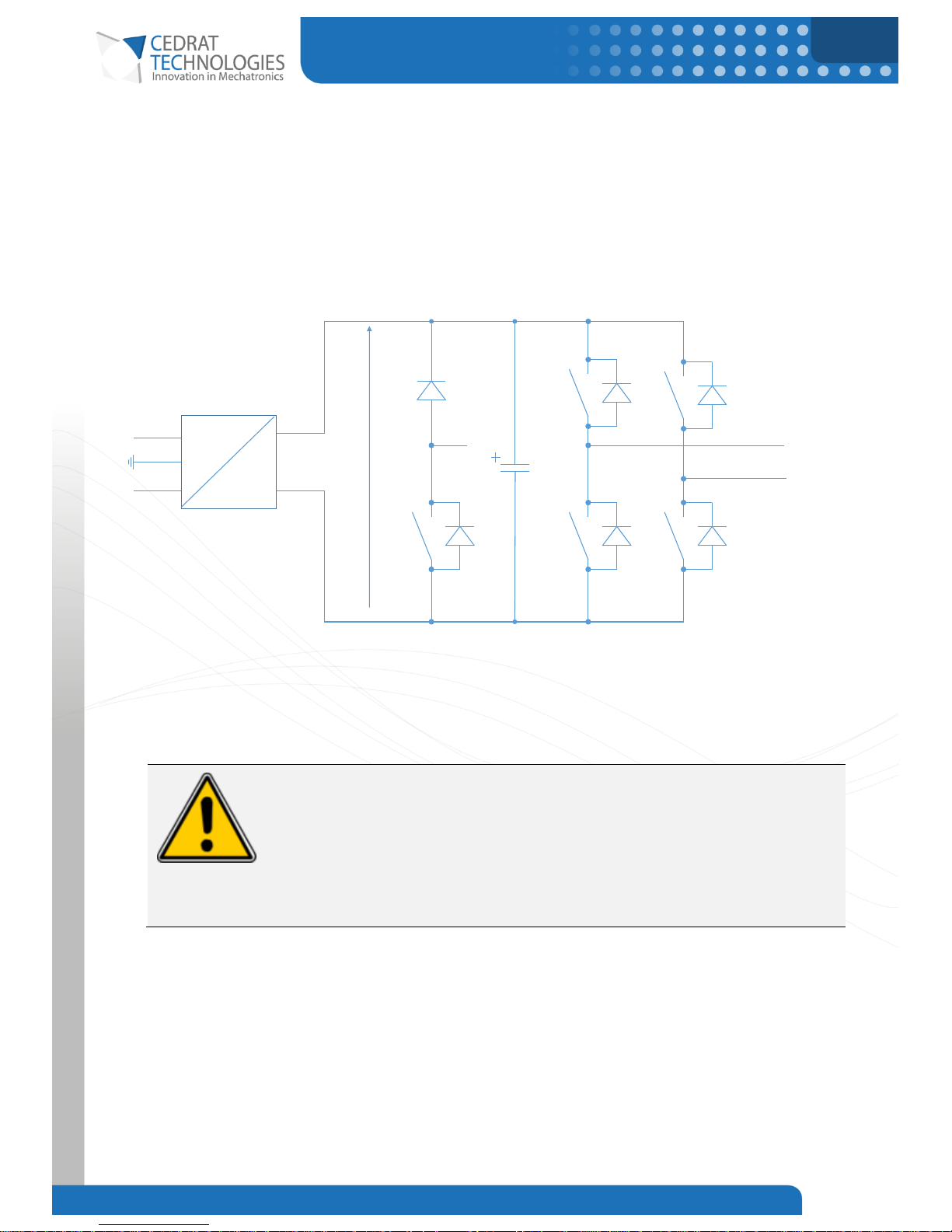
The switching electronic CSA96 is dedicated to supply and control magnetic actuators. The CSA96 includes a
power supply with a maximal power given in the technical data sheet.
Figure 12 – Output stage principle.
The switching amplifier is built around full bridge PWM technology for high efficiency. The switching frequency
of the transistors is 25 kHz. The effective switching frequency on the actuator is 50 kHz.
Warning
The output connections are floating.
The amplifier is only intended to drive magnetic actuators. Connecting capacitive
actuators (such as piezo-actuators) on the outputs of the CSA96 will lead to the
destruction of the amplifier.
8.2. EFFICIENCY AND COOLING
For the internal supply version, the maximum power losses of the amplifier and the internal power supply are
40W (amplifier) and 65W (power supply). With the thermal resistance of the base plate of 0.375K/W, it leads
V+
V-
+
-
Actuator
96V
AC
DC
P
N
B+
B-
Page 21
CURRENT SWITCHING AMPLIFIER
21
CEDRAT TECHNOLOGIES Current Switching Amplifier 18/12/2017
to a temperature rise of 33°C. Much of the time, the ambient temperature is low enough to not use a heat
sink and a fan permitting a substantial cost reduction.
For the external supply version, the power losses of the amplifier can reach 80W due to the increase of the
input voltage to 200Vdc.
The amplifier and the internal power supply are protected against over temperature for a heatsink
temperature of 80°C.
A recommended heat sink is the SK 42 (Fischer Electronik) with 150 mm x 200mm dimensions. It can be cut
to fit the dimensions of the product. Contact Cedrat Technologies for more information.
Worst case power losses with 20A continuous output current and 660W real power:
CSA96-IS
Typical Efficiency
Max Power Losses
Amplifier
98%
40W
Power supply
91%
65W
Those power losses are a worst case because the power losses in the power supply depends on the power
needed by the actuator and the amplifier.
8.3. LIMITATIONS AND PROTECTIONS
8.3.1.Current limitation
An onboard current limitation is implemented to stay below the maximum output current. The default
limitation is tuned to 20A.
8.3.2.Energy recovery
The switching amplifier is well suited to drive reactive load. In this case, the switching amplifier doesn’t
consume the reactive power but only the active power of the actuator plus the losses in the power switching
functions.
Example:
A CSA96 providing 20A at 200Vpp with a sinus waveform (1kVA) to an ideal inductor consumes less than
40W due only to the power components losses of the amplifier. If the inductor is non-ideal, the amplifier will
also deliver the active power (Joules losses and iron losses). This active power cannot be higher than the
maximum power of the power supply (600W).
Page 22
CURRENT SWITCHING AMPLIFIER
22
CEDRAT TECHNOLOGIES Current Switching Amplifier 18/12/2017
8.3.3.Rheostatic braking
The amplifier includes energy recovery capability which is useful to recover the energy stored in electrical
element such as inductance of magnetic actuators and the mechanical energy.
Most of the time the rheostatic braking system is not necessary because linear actuators have a limited stored
energy. However, if the energy to recover is high and no braking system is present, damage on the amplifier
may happen.
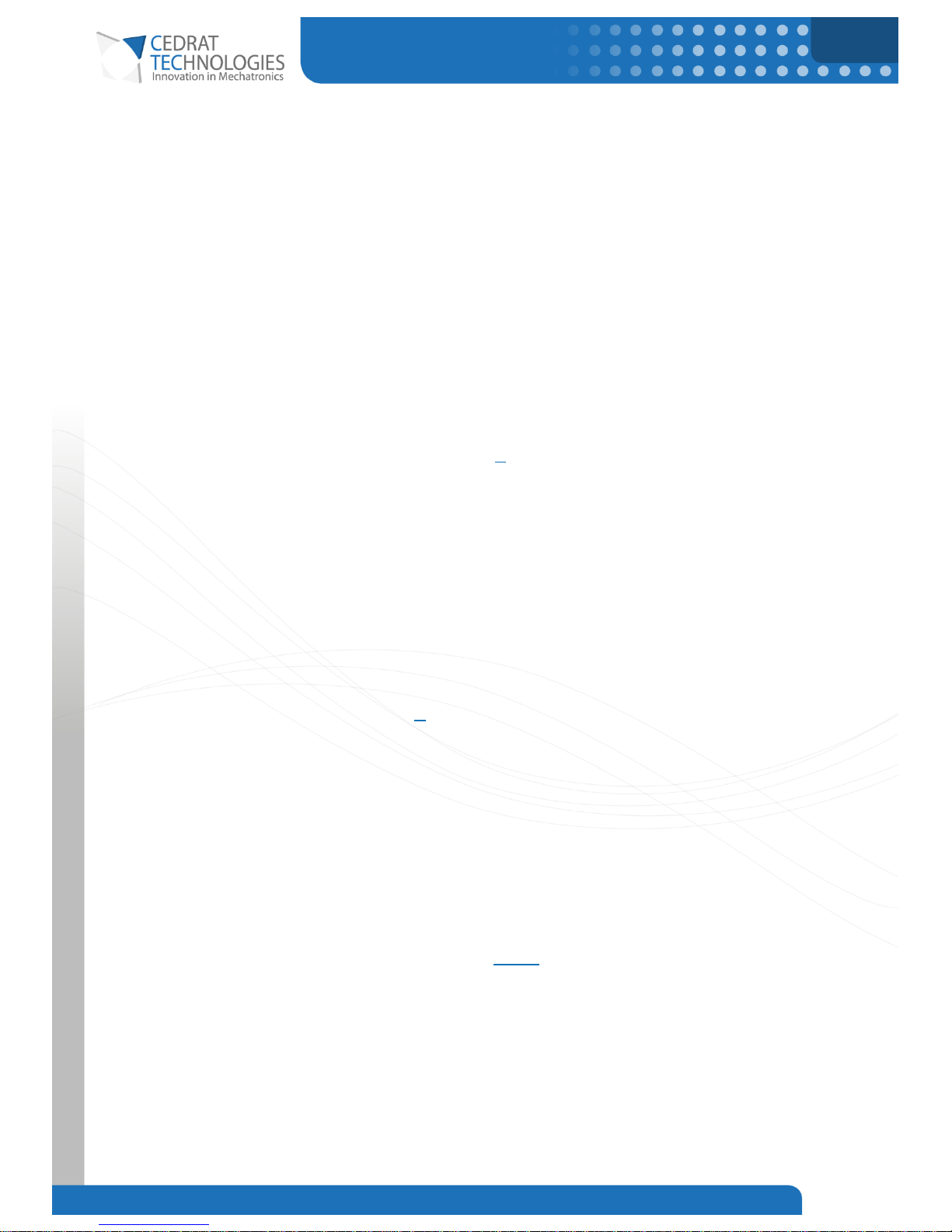
The next equations are a rough estimation of the energy recovered by the amplifier (frictions are neglected).
They consider kinetic and magnetic energy:
Where Δx is half of the full course, F is the maximum force. If this energy is less than 3.5J, there no need for
a rheostat.
Example:
For a MICA200, Δx = 2mm and F = 200N.
Thus, there no need for a rheostat with a MICA200.
When the computed energy is higher than 3.5J, the power of the rheostat needed is:
The resistance value will be:
Vbus = 96V for the internal supply or 200V if an external supply is chosen.
The resistance can’t be lower than 10Ω.
It is up to the user to add margin on the ratings of the rheostat.
Page 23
CURRENT SWITCHING AMPLIFIER
23
CEDRAT TECHNOLOGIES Current Switching Amplifier 18/12/2017
The driver is intrinsically bidirectional but not the internal power supply. Generally, the power supply is not
bidirectional and cannot return energy to the AC source. With large energy to recover, the need to use a
rheostat to dissipate this energy may be necessary.
Warning
If no braking resistor is connected and if the energy to recover is higher than the
internal energy recovery capability of the amplifier, the product may be destroyed.
8.3.4.Buffer capacitor extension
As the preceding equations showed, the stored energy needed may be very close to the energy stored in the
amplifier. In this case, it may be smarter to add a buffer capacitor extension rather than a rheostat as it would
be smaller and more efficient. Ask Cedrat Technologies if the calculated energy needed is larger than 3.5J.
Page 24
CURRENT SWITCHING AMPLIFIER
24
CEDRAT TECHNOLOGIES Current Switching Amplifier 18/12/2017
8.3.5.Minimum output inductance value
For normal operation, the inductance of the actuator is sufficient to provide low di/dt output for EMI and for
proper operation (notably during overload). In this case, no additional output inductor is needed (assuming an
actuator inductance >100µH). However, during a short condition, the current can reach a very high level faster
than the protection system. The overcurrent detection takes about 4µs to trigger. An inductor should be added
in order to further protect the system.
A conservative value for the inductances to be placed at the outputs of the amplifier is 2 x 50µH.
The inductances should be placed in series with the actuator at both outputs.
8.3.6.Protections
The CSA96 includes built-in protection against these fault conditions:
Output over current.
Short circuits of transistors.
Power supply fault.
Over temperature.
Under/Overvoltage.
Warning
The maximum operating ambient temperature is 0°C to 40°C (32 °F to 104 °F).
9. MAIN VOLTAGE CONNEXIONS
The switching amplifier can be connected to the 110VAC or 230VAC main voltage without any modifications.
9.1. CIRCUIT BREAKER
The product does not contain any switch as part of the equipment. Consequently:
a) A switch or circuit-breaker must be included in the installation;
b) It must be suitably located and easily reached;
c) It must be marked as the disconnecting device for the equipment.
Page 25
CURRENT SWITCHING AMPLIFIER
25
CEDRAT TECHNOLOGIES Current Switching Amplifier 18/12/2017
The circuit breaker ratings are given below.
10.
OPERATING INSTRUCTION FOR THE
AMPLIFIER
10.1. GENERAL INSTRUCTIONS
The switching amplifier allows applying to the actuator a signal comparable to the order's one, with a gain of
2A/V.
The order must be applied with a fully differential source to avoid risks of interference and coupling.
The operator should follow the next sequence to assure a proper use of the switching amplifier.
1. Connect the load on the switching amplifier outputs: Vo+ and Vo-.
2. Connect the braking system on B+ and B-.
3. Connect the DB9M shielded cable on the Control Port.
4. Connect the AC source.
5. Turn on the amplifier.
CSA96-IS (110Vac)
CSA96-IS (230Vac)
250V 10A type
250V 5A type
Page 26
CURRENT SWITCHING AMPLIFIER
26
CEDRAT TECHNOLOGIES Current Switching Amplifier 18/12/2017
TROUBLESHOOTING
Problems: Actuator doesn’t move.
Possible Causes
Action
Error in wiring.
Check output connections.
Verify that the Power On and Output ON LEDs
light green.
Verify that the Power Error LED does not light.
Problems: “Power On” LED lights green but “Output On” LED doesn’t light.
Possible Causes
Action
Enable signal is not driven.
Enable signal shall be driven. (5V or 10mA)
Problems: Power On doesn’t light.
Possible Causes
Action
The amplifier is not powered.
Check input connections.
Page 27
CURRENT SWITCHING AMPLIFIER
27
CEDRAT TECHNOLOGIES Current Switching Amplifier 18/12/2017
WARRANTY CONDITIONS AND EXCEPTIONS
The equipment is warranted for one year, including parts and labour, and only under standard technical
conditions as outlined above and expressly mentioned in the technical data sheet. Repairs will be carried out
at CEDRAT TECHNOLOGIES or through your vendor. Shipping, handling and insurance costs to return a part for
repair must be paid by the customer.
Interventions or attempts to service or repair the CSA96 by any unauthorized persons will invalidate this
warranty.
Page 28
CURRENT SWITCHING AMPLIFIER
28
CEDRAT TECHNOLOGIES Current Switching Amplifier 18/12/2017
INSPECTION UPON RECEIPT
This product has been inspected and shown to operate correctly at the time of shipment, as verified by the
Factory Verification Form that accompanies the power supply
Immediately upon receipt of the product, it should be inspected carefully for any signs of damage that may
have occurred during shipment. If any damage is found, a claim should be filed with the carrier.
The package should also be inspected for completeness according to the enclosed packing list. If an order is
incorrect or incomplete, contact your distributor.
CEDRAT TECHNOLOGIES recommends the customer to keep the original package for any further carriage of
the electronic product.
Page 29
CURRENT SWITCHING AMPLIFIER
29
CEDRAT TECHNOLOGIES Current Switching Amplifier 18/12/2017
AFTER-SALES SERVICE
If a device requires service, please contact CEDRAT TECHNOLOGIES or your local vendor. Please include the
device model and serial number in all correspondence with CEDRAT TECHNOLOGIES or your vendor.
Page 30
CURRENT SWITCHING AMPLIFIER
30
CEDRAT TECHNOLOGIES Current Switching Amplifier 18/12/2017
APPENDIX 1
: TROUBLESHOOTING FORM
In case of trouble or breakdown with the electronic device, this form must be completed by the customer in
order to:
- Allow Cedrat Technologies to authorize the product return back to the factory,
- Help Cedrat Technologies in repairing it.
Product: Please give mention here the references and delivery date,
History: Please summarize here every action which has been performed with the device since the delivery,
Problem description: Please describe here the problems faced with the electronics and which are not
described in the paragraph 7,
Notations: Please define here the short term used for external devices plugged in the electronics in order to
make the writing of “problem identification” easier,
Problem identification: Please summarize and describe here, using the “notations”, the operation that could
lead to problem identification,
Action: Please mention and update here every action undertaken by yourself, by Cedrat Technologies or by
your local vendor,
Please note that you need to get the authorization from CEDRAT TECHNOLOGIES before sending back the
hardware.
 Loading...