

Page 1
•
Joint cutters
•
Diamond drilling
•
Table saws
•
Wall saws
•
Wire saws
•
Hydraulic units
•
Special machinery
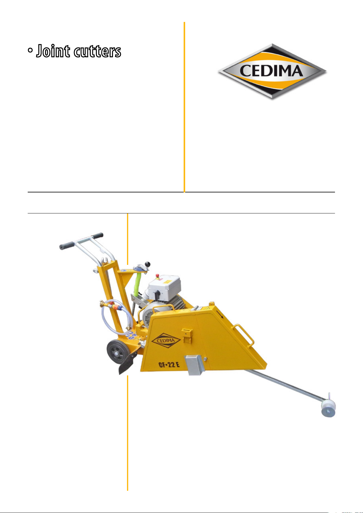
CF•22 E
Change index 004 Issue date 2016-09-21
Translation of the original operating manual
Operating manual
maintenance manual
and safety notes
Page 2
This operating manual has been produced for specialist personnel and for users/operators trained by
specialists!
Read through this operating manual before commissioning and clarify any unanswered questions
with CEDIMA®.
This operating manual is an integral part of the machine, to be passed on with the machine and to be
kept where it is easily accessible at the installation site of the machine.
The displayed and listed tools (workshop equipment) and the diamond saw blades are not part of the
standard scope of delivery of the table saw!
© Copyright CEDIMA®
Diamantwerkzeug- und Maschinenbauges. mbH
Technical Documentation
Translation of the original operating manual
All rights reserved according to DIN ISO 16016. No part of this document may be reproduced,
customised, sent to another, transmitted, stored in a data storage device or translated into another
language without obtaining prior written approval, unless permitted under the copyright.
The information contained in this document can be changed without any prior notice being given.
CEDIMA® only accepts the legally required guarantee for this documentation.
CEDIMA® assumes only the legally liability for errors which may be contained in this operating manual/
spare parts list nor for any incidental or consequential loss or damage that may arise in connection with
the delivery, performance or use of the material beyond the legal requirements.
Trademark
Name and logo are registered trademark of
CEDIMA® Diamantwerkzeug- und Maschinenbauges. mbH
Celle/Germany
• CEDIMA® • Technical Documentation • All rights reserved according to ISO 16016 • Changes serving technical progress reserved •
Page 3
EC Declaration of Conformity
Manufacturer:
CEDIMA
Lärchenweg 3, D-29227 Celle/Germany
Collection and storage of the technical documentation:
Technical documentation of
CEDIMA
Siedemeierkamp 5, D-29227 Celle/Germany
Machine description:
Walk-behind hand-guided for wet cutting in asphalt and concrete as well as similar abrasive
construction materials with diamond saw blades up to 700 mm diameter in left or right cutting.
Cutting shaft drive via V-belts with a 7.5 kW electric motor. Maximal cutting depth of 270 mm
progressively and rmly adjustable via frame rocker and threaded rod. Pressurised water supply
provided by GEKA-connection and adjustable shut-o valve. Dismountable in 3 modules for transport.
Measured acoustic power level: LWA= 94 dB (A)
Guaranteed acoustic power level: LWA(d)= 98 dB (A)
®
Diamantwerkzeug- und Maschinenbauges. mbH
®
Diamantwerkzeug- und Maschinenbauges. mbH
Procedure for assessing the conformity: RL 2000/14/EC, Appendix V
Hereby we conrm that in the sense of EC Directive 2006/42/EC, Annex II1.A dated 2006-05-17
(modications inclusive) of the European Parliament and the Council
the joint cutter CF•22 E from the year of manufacture 2009
complies with the following harmonised standards and EU Directives:
EN ISO 12100-1, EN ISO 12100-2, EN 13862, EN ISO 14121-1, EN 60204-1, 2000/14/EC, 2002/96/EC
In regard to dangers due to electricity, according to Annex I No. 1.5.1 of the Machinery Directive
2006/42/EC, the protective aims of the Low Voltage Directive 2006/95/EC (formerly 73/23/EEC) are
met.
In regard to dangers due to radiation, according to Annex I No. 1.5.10 of the Machinery Directive
2006/42/EC, the protective aims of the EMC Directive 2004/108/EC (formerly 89/336/EEC) are met.
This declaration of conformity immediately becomes invalid if changes are incorporated to the
machine which have not been approved by us!
Celle, 2016-09-21
• CEDIMA® • Technical Documentation • All rights reserved according to ISO 16016 • Changes serving technical progress reserved •
Bob Siemsen (managing director)
Page 4
Contents of this operating manual CF•22 E
EC Declaration of Conformity
Chapter 1 Technical data and accessories
Chapter 2 Description of the joint cutter CF•22 E
Chapter 3 Basic safety instructions for joint cutters
Chapter 4 Preparation and operation
Chapter 5 Maintenance and care
Chapter 6 Taking back / disposal of the equipment
Chapter 7 Troubleshooting – What to do if. . .?
Chapter 8 Terms of warranty
• CEDIMA® • Technical Documentation • All rights reserved according to ISO 16016 • Changes serving technical progress reserved •
Page 5
Technical data and accessories
1.0 Technical data and accessories for the CEDIMA® joint cutter CF•22 E
1.1 Technical data
Drive motor
Max. motor output
Speed
Voltage
Amperage
Starting device
electric motor
7.5 kW
2900 min
-1
400 V / 50 Hz
16 Ampere
Star Y delta ∆ reversing switch
Type of protection IP 54
Blade mounting Ø 25.4 mm
Drive pin Ø 8,0 mm
Max. saw blad clamping width 6,0 mm
Cutting shaft rpm 1630 min
-1
Max. saw blade diameter 700 mm
Max. cutting depth 270 mm
Cutting depth adjustment manually over a lockable hand crank (threaded spindle)
Saw blade receptacle side right or left
Feed manuell
Water supply Pressurised water with GEKA connection
Length / width / height 1350 mm / 660 mm / 930 mm
dismountable in:
Rocker with motor and cutting shaft
Sound pressure level at the workplace *
Measured acoustic power level *
* Higher values are possible during cutting.
Dimensions
Weight
Frame
Blade guard
110 kg
60 kg
30 kg
20 kg
L
= 78 dB (A)
PA
LWA = 94 dB (A)
• CEDIMA® • Technical Documentation • All rights reserved according to ISO 16016 • Changes serving technical progress reserved •
5
Page 6
1.2 Vibration acceleration values, hand-arm vibration
Technical data and accessories
Equivalent total vibration rating a
Measurement uncertainty K m/s²
The given values can vary as they depend on the application conditions (the material that has to be cut, the state of the
machine, handling, the operator and the diamond tools being used, etc.).
The actual period of exposure, which can be considerably aected by the non-productive times (reduced), must always be
taken into consideration when determining the daily vibration load A(8) as per DIN EN ISO 5349-2. The following count as
non-productive times: time needed for relling with fuel, dealing with the water supply, changing the tools, setting up and
moving the machine, etc., as well as securing the workplace, the area of operation.
Uncertainties in measurement according to DIN EN 12096.
Aparameter calculator for determining the daily vibration rating (daily vibration load A(8)) can be found on the internet
e.g. The German Accident Insurance (DGUV) and/or the Trade Association sites (BG).
hv, eq
< 2,5 m/s²
DANGER
Risk of being injured when exceeding the highest permissible daily vibration load!
At uninterrupted work with the CF•22 E the daily maximum value is not reached (noise and accident prevention
regulation).
1.3 Accessories provided:
1 x double open-ended spanner SW 17/36
1 x operating manual
1 x spare parts list
No liability will be accepted for any damage that results from using accessories that do not comply with the
CEDIMA®
Details for aiding in the selection of the correct diamond saw blade can be obtained in the current price list as well
as in the current joint cutter brochure
Contact CEDIMA® directly in the case of special applications.
Alist of additional accessories can be found in the current CEDIMA® price list.
specications.
• CEDIMA® • Technical Documentation • All rights reserved according to ISO 16016 • Changes serving technical progress reserved •
6
Page 7
Description of the joint cutter CF•22 E
2.0 Joint cutter CF•22 E
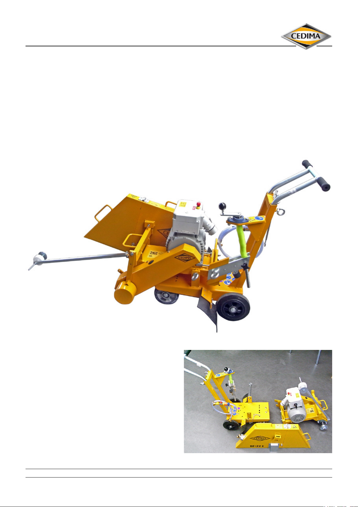
The electrically driven CF•22 E is intended to be used as joint cutter / ground parting-o grinder for wet cutting, using
diamond saw blades. In places where due to exhaust and/or noise protection regulations machinery with internal
combustion engines cannot be used (e.g. closed rooms).
In spite of the compact design the CF•22 E can achieve a cutting depth of 270 mm and thus allowing more demanding
cutting works.
The construction in 3 easily transportable modules enables trouble-free transport and the assembling of the CF•22E at
workplaces dicult to access.
Assembly and dismantling of the subassemblies is done in just a few steps, no extra tools are necessary.
Figure 2.1
The weight distribution resulting from the arrangement
of all the components of the CF•22 E on this joint cutter
means that sucient pressure is applied to the diamond
saw blade, at the same time making the machine easy to
handle when setting it up and repositioning.
The modular design facilitates cleaning, maintenance and
if necessary the repair.
Separated in modules Figure 2.2
• CEDIMA® • Technical Documentation • All rights reserved according to ISO 16016 • Changes serving technical progress reserved •
7
Page 8
Description of the joint cutter CF•22 E
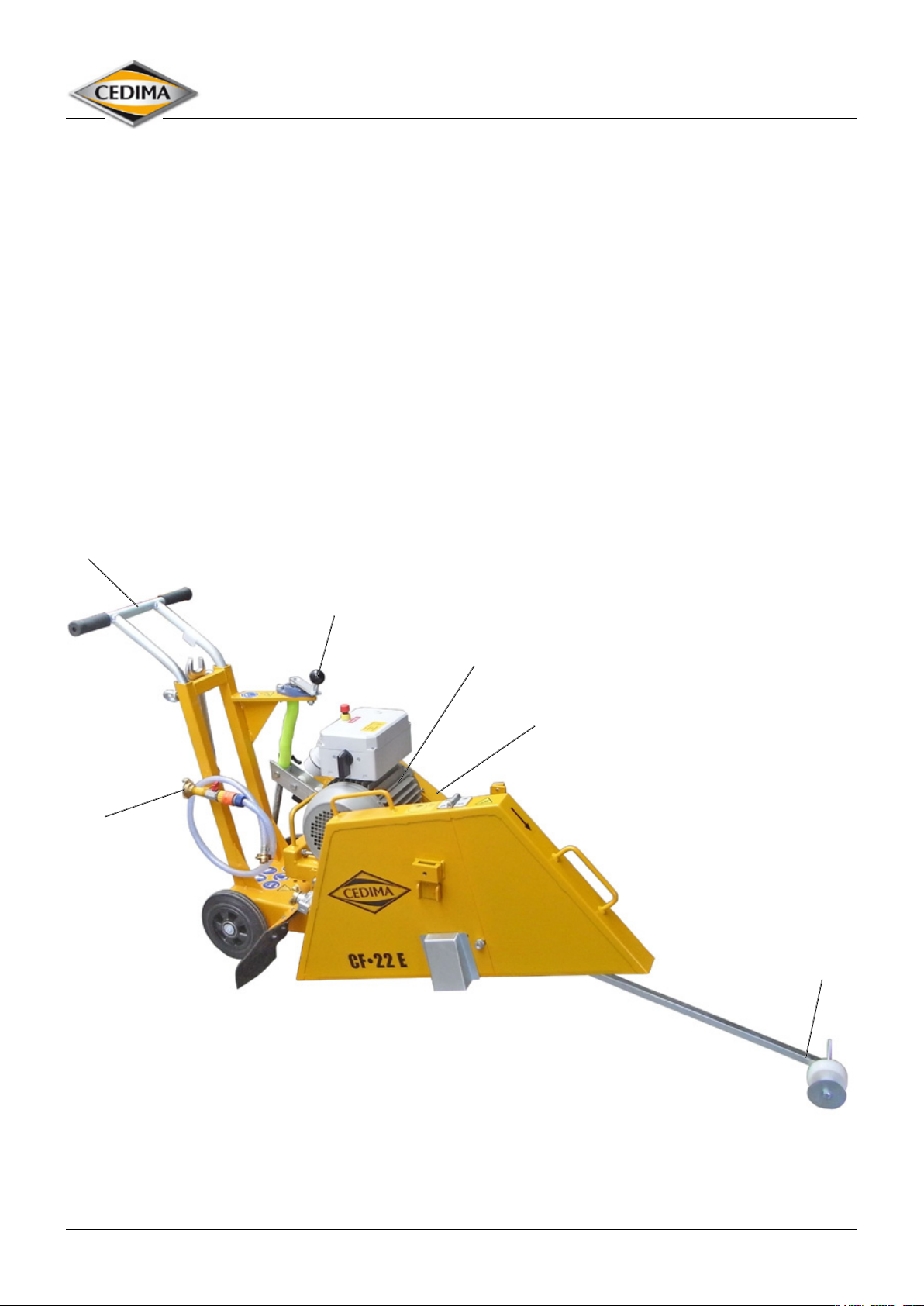
The cutting shaft with the diamond saw blade is driven by
amodern, powerful electric motor over aV-belt.
The blade mounting is right or lef possiblet. For this pur-
pose the blade guard mounting side must be changed.
The feed is performed manually by pushing on the adjusta-
ble push handle.
Lowering and raising the diamond saw blade takes place
exactly and quickly over alockable hand crank with
athreaded spindle.
By using the innite cutting depth adjustment it is possible
to achieve cutting depths of up to 270 mm.
The cutting shaft is mounted in two selfaligning pedestal
bearings. The precision-engineered shaft has a 25.4 mm
diameter blade mounting ange.
Adjustable/removable
push handle
Lockable hand
crank for cutting
depth adjustment
The front pointer, which is mounted on the joint cutter
frame, enables the user to cut accurately along aline.
The water supply of the saw blade occurs over pressurised
water from an external hose which is to be connected to
the shut-o valve using aGeka coupling
The drive unit and cutting shaft rpm are designed in such
away that they create the optimal conditions for cutting
with CEDIMA® diamond saw blades.
We recommend the CEDIMA® diamond saw blades as
acutting insert since they achieve preservation of the joint
cutter due to their cutting capacity and smooth running
Gekawater connection
with shut-o
valve
Powerful
electric motor
V-belt drive
Front pointer
Figure 2.3
• CEDIMA® • Technical Documentation • All rights reserved according to ISO 16016 • Changes serving technical progress reserved •
8
Page 9
Basic safety instructions
for joint cutters
3.0 Basic safety instructions
ATTENTION
Read and observe all operating manuals pertaining to
the joint cutter!
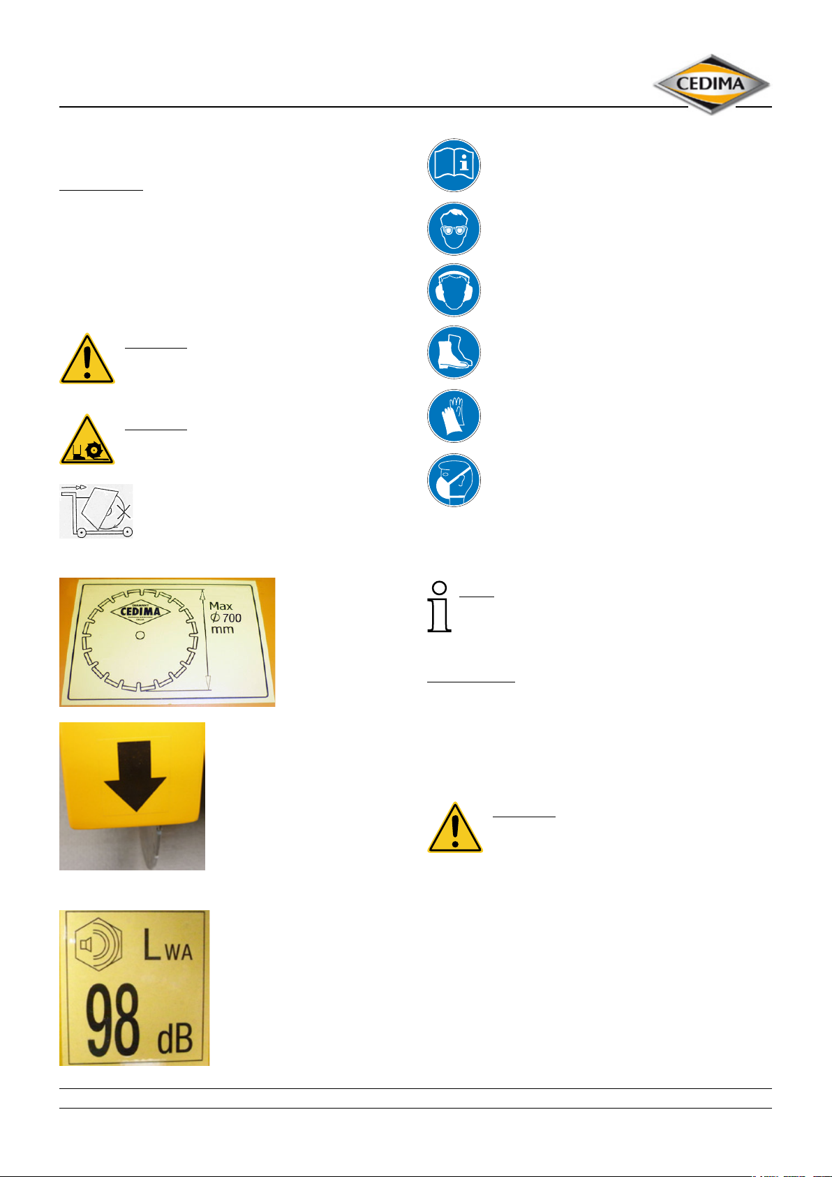
3.1 Icons, symbols, notes
The following signs and symbols are used at the joint cutter
for information of special importance:
DANGER
Warning of a hazard area!
DANGER
Warning of cutting shaft, saw blade!
To move the joint cutter beyond the cutting
area, stop the tool!
Read the operating manual!
Use eye protection!
Use hearing protection!
Use foot protection!
Use hand protection
Use light breathing protection
Maximum
mountable saw
blade diameter!
(450 mm)
Direction of rotation of saw
blade / cutting shaft (on the saw
blade guard)
Guaranteed sound pressure
level
The following designations or characters are used in the
operating manual for particularly important information:
Note
Special instructions regarding economic use. The advice
that follows after the "Note" symbol contains important
information that diers from other text!
ATTENTION!
Special information regarding instructions and prohibitions
for avoiding damage. The advice that follows after the
"ATTENTION!" symbol contains instructions that must be fully
complied with in order to prevent damage occurring to the
ttings or material as well as injuries to the operator or third
parties!
DANGER
Details or regulations and prohibitions for
the prevention of injuries to personnel and/or
extensive equipment damage. The advice that follows after
the "DANGER" symbol warns you that ignoring the relevant
instructions or procedural instructions might result in the
operator or third parties being injured!
Important passages are always written in italics!
Text passages relating to safety are always shown in bold
lettering, in italics!
• CEDIMA® • Technical Documentation • All rights reserved according to ISO 16016 • Changes serving technical progress reserved •
9
Page 10

Basic safety instructions
for joint cutters
3.2.1 Designated use, predictable misuse
3.2.1.1 The joint cutter CF•22 E, in the following referred
to as machine, is exclusively to be used as walk-behind
hand-guided oor cutting machine for cutting by means
of diamond saw blades in wet cutting operation of rmly
installed components made of asphalt, concrete and
abrasive construction material as used e.g. in roadwork,
hall oors and runways! Using the machine for purposes other than those mentioned above is considered
contrary to its designated use; in particular the use of
the machine with cutting tools other than those approved by the manufacturer/distributor is prohibited. The
manufacturer/distributor cannot be held liable for any
damage resulting from such use. The risk of such misuse
lies entirely with the user.
3.2.1.2 The machine is not approved for other use than the
one specied herein; this constitutes improper use.
3.2.1.3 Operating the machine within the limits of its
designated use also involves observing the instructions
set out in this operating manual and complying with the
inspection and maintenance directives.
3.2.1.4 The machine has been designed in accordance with
state-of-the-art standards and recognized safety rules.
Nevertheless, its use may constitute a risk to life and limb
of the user or of third parties, or cause damage to the
machine or other material property.
3.2.1.5 The machine must only be used in technically
perfect condition in accordance with its designated use,
the instructions set out in the operating manual and
the relevant national safety regulations, and only by
safety-conscious persons who are fully aware of the risks
involved in operating the machine. Any functional disorders, especially those aecting the safety of the machine,
must therefore be rectied immediately.
3.2.2 Organisational measures
3.2.2.1 This operational manual must always be kept at
the hand at the machine operating site and must be
accessible to operating personnel at all times!
3.2.2.2 In addition to the operating manual, generally
applicable legal and other binding rules and regulations
for accident prevention and environmental protection
must also be observed! Such duties can, for example,
also concern the handling of dangerous substances, the
provision/wearing of safety equipment or road trac
regulations!
3.2.2.3 Additionally this operating manual with instructions, including supervisory and reporting duties for
taking special plant situations should be observed, e.g.
with regard to work organisation, working procedures,
personnel used, ect.
3.2.2.4 The personnel charged with activities at/on the
machine must have read th
beginning work! This is also especially applicable to personnel which only works at the machine occasionally (e.g.
during set-up/take down, maintenance work)!
3.2.2.5 Safety and danger-conscious working of the
personnel under observance of the operating manual
must be checked at least occasionally!
3.2.2.6 The personnel must tie back long hair and may not
wear loose clothing or jewellery, including rings! There
is a danger of injury (e.g. by becoming caught or being
pulled in by moving parts)!
3.2.2.7 If necessary or required by regulations, personal
safety equipment must be used (e.g. protective goggles,
hearing protection, safety shoes and safety clothing)!
Corresponding to working conditions, the wearing of
further personal safety equipment (protective clothing)
may be necessary! The accident prevention regulations
must be observed at all times!
3.2.2.8 All safety- and danger warnings at, in and on the
machine must be observed and must always be kept in
proper, legible condition!
3.2.2.9 In case of safety-relevant changes to the machine or
its operation, shut down the machine immediately and
report the fault to the responsible oce/person!
3.2.2.10 Safety equipment at, in or on the machine may
never be removed or rendered inoperative!
3.2.2.11 Changes, attachments and modications to the
machine which could impair safety are not permitted
without the approval of the manufacturer/supplier! This
also applies to the installation and adjustment of safety
equipment, and to welding and drilling on load-bearing
parts!
3.2.2.12 Replace defective or damaged machine parts
immediately! Only use original spare parts!
3.2.2.13
3.2.2.14 The intervals for repetitive testing or inspection
3.2.2.15 Hydraulic hoses must be replaced at the specied
3.2.2.16 To conduct maintenance measures, suitable
3.2.2.17 The ability to report and ght re must be ensured,
Spare parts and tools must correspond to the
technical requirements set down by the manufacturer/
supplier! This is guaranteed by using original spare parts!
of the machine required by law or specied in this
operating manual must be complied with!
or suitable intervals, even if no safety-relevant defects
are apparent!
workshop equipment and corresponding specially
trained personnel are always required!
and all employees must be informed of the location and
operation of extinguishing equipment!
e operating manual prior to
• CEDIMA® • Technical Documentation • All rights reserved according to ISO 16016 • Changes serving technical progress reserved •
10
Page 11

Basic safety instructions
for joint cutters
3.2.3 Selecting qualied sta
3.2.3.1 Work on and with the machine may only be carried
out by reliable personnel. The legal minimum age must
be observed!
3.2.3.2 Only use trained or instructed personnel! The
responsibilities of the personnel for the operation,
preparation, maintenance and repair of the machine
must be clearly dened!
3.2.3.3 It must be ensured that only authorised, skilled
personnel use or handle the machine!
3.2.3.4 Specify the responsibility of the machine operator
with regard to trac laws and regulations and enable
him/her to refuse to follow any instructions of others
which would aect safety!
3.2.3.5 Personnel to be trained or instructed, or who are
participating in general training may only use the
machine when supervised by an experienced person!
3.2.3.6 Work on electrical components and equipment
may only be carried out by an electrician or instructed
persons under the direction and supervision of an
electrician in accordance with the rules of electrical
engineering!
3.2.3.7 Hydraulic equipment may only be worked on by
personnel with a special knowledge of and experience in
hydraulics!
3.2.4 Safety information on
certain operation phases
I. Normal operation
3.2.4.1 Always familiarise yourself with the work site and
surroundings before starting work! The work-site and
surroundings include, for example, the obstacles in the
working and trac area, the load-bearing capacity of the
ground and the measures required for securing the work
site!
3.2.4.2 Assemble the machine on an even, stable and
hard ground! The stableness is to be ensured. Clear the
ground of all things that could impede the work!
3.2.4.3 Ensure a safe stand on even, rm, stable ground and
make sure to keep the balance any time.
3.2.4.4 Avoid any manner of working with the machine
which could present a safety risk!
3.2.4.5 Machines which are driven by a combustion engine
must only be lled with the fuel recommended by the
manufacturer. Pay attention to the danger of re and
explosion when lling the tank! Do not spill fuel onto hot
machine parts.
3.2.4.6 Keep to the conditions given by the manufacturer
concerning the connections for electricity and water.
3.2.4.7 Make sure that the machine is only used when in
a safe, operative condition! Only operate the machine
when all safety equipment and safety-related equipment
(e.g. guards, emergency-stop devices, noise insulation
etc.) are present and operative!
3.2.4.8 Each time before you start working and at least
once per shift, check the machine for obvious damage
and defects. Any changes (including changes in the
performance or behaviour of the machine) must
be reported to the competent authority/person
immediately.
If required, shut down the machine immediately and
secure it.
3.2.4.9 In the event of malfunctions or if the machine
behaves dierently, shut it down immediately and
prevent it from being restarted. Have faults rectied
immediately!
3.2.4.10 The following must be checked before starting
cutting operations:
– the diamond saw blade for compatibility to the direc-
tions given by the manufacturer regarding the drilling
method (wet or dry cutting) and the kind of work to
be performed
– the proper condition of the diamond saw blade (no
deformation, damages)
– the diameter of the saw blade recommended by the
manufacturer
– the cutting speed (RPM.) of the diamond saw blade
(max. RPM) of the machine recommended by the
manufacturer
– the accordance of the machine`s direction of cut to the
direction of cut of the diamond saw blade
– the compatibility of the diamond saw blade to the
arbour (ange)
– that the saw blade clamping tools (spanners) have
been removed,
– the rm seating of the diamond saw blade. Secure the
t of the diamond saw blade (mounting according
to recommendations of the manufacturer, with only
original screws!
3.2.4.11 The direction of rotation of machines with electrical AC motors or hydraulic drive must be maintained to
prevent loosening of the saw blade!
3.2.4.12 Observe the procedures for switch-on and switcho, as well as the indicating devices described in the
operating manual!
3.2.4.13 Before switching on the machine or putting it into
gear, make sure that it cannot pose a danger to anyone
during start-up or operation.
• CEDIMA® • Technical Documentation • All rights reserved according to ISO 16016 • Changes serving technical progress reserved •
11
Page 12

Basic safety instructions
for joint cutters
3.2.4.14 Only qualied operators are to be in the range
of the machine. Other persons are to be kept at a safe
distance!
3.2.4.15 The machine may only be started from the
operators/drivers place (CF•22 E at the back of the
machine)!
3.2.4.16 Take precautions to ensure that the operator
always has an adequate view of the working area and
can intervene in the work process at any time!
3.2.4.17 Before starting work, make sure that all brakes,
steering, signals and lighting are in working order!
3.2.4.18 Hydraulic and water hoses as well as electrical
cables must be installed so that damage by tools or the
machine are not possible!
3.2.4.19 Cutting must be carried out with water to prevent
the forming of health-endangering ne dusts, and to
increase the service life of the cutting tool!
3.2.4.20 When wet-cutting, make sure that enough water is
available where it is needed. Cooling water supply must
always follow the cutting process!
3.2.4.21 When working at dry-cutting, make sure of sucient dust removal.
3.2.4.22 When unhealthy or explosive substances are released (dust, sludge) observe the national safety regulations!
3.2.4.23 Moving the machine outside the working area may
only be done with the saw blade removed!
3.2.4.24 When the machine is to be driven on public highways, roads and places, the relevant trac laws must be
observed and, if necessary, make sure that the machine
complies with the relevant road vehicle regulations!
3.2.4.25 Before moving the machine, always make sure that
the accessories are safely stored!
3.2.4.26 Do not drive transversely across inclines steeper
than 5%!
3.2.4.27 Inclines steeper than 15% may only be negotiated
with the aid of one or more safety lines!
3.2.4.28 When leaving the machine unattended, it must
always be secured against being switched on again
accidentally!
3.2.4.30 Inform the operating personnel before the start of
special- and maintenance work! Name the responsible
supervisor!
3.2.4.31 During all work concerning the operation,
adaption for production, conversion or adjustment of
the machine and its safety-related equipment, as well
as inspection, maintenance and repair work, observe
the procedures for switching the machine on and o as
described in the operating manual and the information
on performing maintenance work!
3.2.4.32 Block o a large area around the maintenance area
if necessary!
3.2.4.33 Service and repair work may only be carried out
with a fully lowered cutting shaft/frame or through
securing the frame by means of approved trestles.
Hydraulic valves for raising the frame must be opened
(pressure relief).
3.2.4.34 Only conduct maintenance and repair work with
the machine standing on a level surface with sucient
load-bearing capacity and secured against rolling!
3.2.4.35 If the machine is completely shut down during
maintenance and repair work, it must be secured against
accidentally being switched on again:
– remove the key and/or disconnect the power supply!
– install a warning sign!
3.2.4.36 During replacement, individual parts and larger
assemblies must be mounted and secured carefully on
lifting equipment, so that they cannot present a danger!
Only use suitable lifting equipment and load attachment
devices in proper technical condition and with a
sucient load-bearing capacity! Never stand or work
under hanging loads!
3.2.4.37 Only charge experienced persons with the
attachment of loads and the instructing of crane or
industrial truck operators. The person giving instructions
must be within sight of or must have voice contact with
the operator!
3.2.4.38 Before maintenance/repairs, clean the machine
and remove any grease, dirt or residues left by protective
substances from the connectors or screw joints. Never
use aggressive cleaners (detergents)! Use a lint-free
cloth!
II. Special work related to the
maintenance and repair of the machine
and troubleshooting, disposal
3.2.4.29 Observe the adjustment, maintenance and
inspection work and intervals set down in the operating
manual, including the specications for the replacement
of part and assemblies. This work may only be carried
out by specially trained personnel!
• CEDIMA® • Technical Documentation • All rights reserved according to ISO 16016 • Changes serving technical progress reserved •
12
3.2.4.39 Before cleaning the machine with water or any
other cleaning solution, cover or mask o all openings
into which no water, steam or cleaning agents may enter
for safety and operational reasons! Ball bearings, electric
motors and control cabinets are particularly endangered!
Pay attention to special types of protection!
3.2.4.40 The cover/taped protection must be completely
removed after cleaning!
Page 13

Basic safety instructions
for joint cutters
3.2.4.41 Following cleaning, inspect all cable and hydraulic
connections for leaks and/or loose connections, for
rub spots and damages. Have any defects rectied
immediately!
3.2.4.42 Any bolted joints which have been undone during
maintenance and repair work, must always be tightened
up again afterwards!
3.2.4.43 If it is necessary to remove safety equipment
during preparation, maintenance and repair work,
then this safety equipment must be mounted and
checked immediately following the completion of the
preparation, maintenance and repair work!
3.2.4.44 Always keep a safe and sucient distance to edges
of excavations, ditches and slopes!
3.2.4.45 Refrain from any manner of working which may
aect the stability of the machine under load!
3.2.4.46 Before leaving the machine, secure against it
rolling away inadvertently!
3.2.4.47 Ensure that all process materials, auxiliary materials
and replaced parts are disposed of in a safe and
environmentally favourable way!
3.2.5 Information about special risks
related to electric energy
3.2.5.1 Electric connections are only permitted in CEapproved mains networks with appropriate fusing and
fault current safety switch.
3.2.5.2 Observe the pertinent DIN/VDE regulations!
3.2.5.3 Electrical connections must always be free of dirt
and moisture!
3.2.5.4 Only use original fuses with the specied amperage!
Switch o the machine immediately in the case of faults
in the power supply!
3.2.5.5 Avoid physical contact with earthed parts e.g. pipelines (danger by electric shock).
3.2.5.6 After touching or cutting lines carrying high voltage:
– Let go of the machine but do not leave it unattended!
– Run the machine (saw blade) out of the danger area
provided it is possible without endangering the operator!
– Warn outsiders against approaching and touching the
machine!
– Have the voltage switched o!
– Only leave the machine when the cable touched or
damaged has denitely been de-energised!
3.2.5.7 Always keep the machine in a sucient distance
from electrical overhead cables! When working near
electric overhead cables, the equipment must not come
near the cables! DANGER TO LIFE !!!
Find out about the safe distances to be maintained!
3.2.5.8 Work on the electrical system or equipment
may only be carried out by a qualied electrician or
by properly instructed personnel working under the
supervision of a qualied electrician and in accordance
with the applicable electrical engineering rules.
3.2.5.9 Machine parts on which inspections, maintenance
and repair work is carried out , must be de-energised
if required! First check the de-energised parts to make
sure there is no voltage, then earth and short-circuit and
isolate adjacent live parts!
3.2.5.10 The electric parts of the machine must be regularly
inspected and thoroughly checked! Any faults – e.g.
loose connections or charred cables must be cleared
immediately!
3.2.5.11 When work has to be carried out on the life parts, a
second person must be present to cut the power supply
or turn the main power o in case of an emergency! The
work area must be secured with a red and white warning
chain and a warning sign! Use voltage-insulating tools
only!
3.2.5.12 When working on high-voltage assemblies after
switching o the voltage, connect the supply cable to
earth and short-circuit the components, e.g. capacitors,
using the earth rod!
3.2.5.13 If used, mobile electrical apparatus, connecting
cables with plugs, extension cables and equipment
power cables with there plugs attachments are to be
checked at least once every six month by an electrician
or by means of suitable testing apparatus operated by a
person with knowledge of electrics, to ensure that they
are functioning correctly!
3.2.5.14 Protective installations with fault current
protection units are to be checked for their eectiveness
at least once a month by a person with knowledge of
electrics!
3.2.5.15 Residual-current and residual-voltage protective
devices must checked regularly for proper operation by
actuating the test facility:
– once each working day for mobile systems
– at least once every six month for a stationary system!
3.2.6 Gas, dust, vapour and smoke
3.2.6.1 Welding, grinding, sanding or using a ame on
the machine is prohibited unless it has been explicitly
permitted!
3.2.6.2 Before welding, grinding or using a ame, the
machine and the surrounding area must be cleaned of
dust and combustible materials and sucient ventilation
provided (danger of explosion)!
3.2.6.3 Observe any applicable national regulations when
working in conned spaces!
• CEDIMA® • Technical Documentation • All rights reserved according to ISO 16016 • Changes serving technical progress reserved •
13
Page 14

Basic safety instructions
for joint cutters
3.2.6.4 Combustion engines must be used in suciently
ventilated rooms only! Never leave the engine running in
enclosed or conned spaces! The exhaust fumes contain
the poisonous gas carbon monoxide!
3.2.6.5 Check all pipes and lines, hoses and screwed joints
for leakage and visible damage! Clear any faults immediately / have any faults cleared immediately!
3.2.7 Noise
3.2.7.1 Noise-absorbing elements of the machine must be
in their proper places during operation of the machine!
3.2.7.2 Wear hearing protection as required (e.g. according
to the valid accident prevention laws/occupational
health and safety laws)!
3.2.8 Lighting
3.2.8.1 The machine is designed for use in daylight only!
The operator must make sure that adequate lighting is
provided in unlit working areas!
3.2.9 The handling of uids, lubricants and
other chemical substances
3.2.9.1 When handling pressure uids, lubricants, greases or
conservation agents (hereinafter referred to as operating
materials or lubricants), the safety regulations applicable
for the respective product must be observed!
3.2.9.2 Avoid prolonged contact of operating materials
and lubricants with the skin! The skin must be carefully
cleaned of adhesive operating materials and lubricants!
3.2.9.3 Be careful when handling pressurised liquids! There
is a risk of injury due to hydraulic uid escaping at high
pressure! Never tamper with the hydraulic system,
especially not with the pipes and hoses!
3.2.9.4 Exercise caution when handling hot operating
materials and lubricants, as there is a danger of burns or
scalding! Particularly at liquid temperatures above 60 °C,
avoid any skin contact with these liquids!
3.2.9.5 If operating materials or lubricants get into the eyes,
ush thoroughly with drinking water! Then visit a doctor!
3.2.9.6 Immediately clean up any operating materials
or lubricants which have leaked out! Use absorbent
material for this purpose!
3.2.9.7 Operating material and lubricants must not be
allowed to seep into the soil or get into the public
sewage system!
3.2.9.8 Properly collect, store and dispose of operating
materials and lubricants which can no longer be used!
3.2.9.9 Observe and follow the respective applicable laws
and regulations for handling operating materials and
lubricants and their disposal in the country in which
these substances are used! Obtain information from the
responsible agencies!
3.2.10 Transporting the machine
3.2.10.1 Observe the relevant regulations, directives and
standards.
3.2.10.2 Use hoisting tools and oor-level conveyors with
loads
> 25 kg.
3.2.10.3 For loading or transporting the machine, use only
lifting and transporting devices and equipment with a
sucient bearing force!
3.2.10.4 Determine an experienced instructor for the lifting/hoisting process!
3.2.10.5 Only lift the machine properly in accordance with
the operating manual (position, points of attachment for
hoisting devices), using hoists!
3.2.10.6 Only use a suitable transport vehicle with sucient
load-bearing capacity!
3.2.10.7 For transport, the saw bade has to be dismantled!
3.2.10.8 Before transporting the machine, always make sure
that the accessories are stowed away in such a way that
they cannot cause an accident!
3.2.10.9 The machine must always be kept straight and
horizontal, otherwise the operating material, fuel and/or
oil will run out of the machine!
3.2.10.10 Secure the load reliably! Use suitable attachment
points!
3.2.10.11 Before loading, secure the machine and its assemblies to ensure that it cannot move accidentally! Attach
a corresponding warning sign! Remove the devices
properly before putting into operation again!
3.2.10.12 Carefully remount and secure parts that must
be removed for transport purpose before putting into
action again!
3.2.10.13 Even when relocating slightly, disconnect the
machine from any external power supply! Before putting
into operation again re-connect the machine properly to
the power supply!
3.2.10.14 When resuming operation, only proceed as described in operating manual! The machine may only be
installed and operated in accordance with the instructions of this operating manual!
• CEDIMA® • Technical Documentation • All rights reserved according to ISO 16016 • Changes serving technical progress reserved •
14
Page 15
Set-up and operation
Joint cutter CF•22 E
4.0 Set-up and operation
4.0.1 To be checked on delivery
First check the completeness and intactness of your
CEDIMA® joint cutter CF•22 E. You will nd the scope of the
delivery in the chapter “Technical data and accessories”.
The joint cutter can be put into operation with no special
eort or installation procedure. However, when setting up
and operating the machine it is important to observe the
notes shown below, as well as the general safety regulations and safety instructions for the operation of the
engine.
4.1 Preparing the joint cutter
4.1.1 Assembling/dismantling
the joint cutter
Assembling:
– Grease all connecting elements before each assembly.
– Place rocker with motor and cutting shaft down into the
bearin on the trolley.
– Insert the central bolt and secure by means of the spring
pin.
– Fix the connecting plate for the hight adjustment onto
the rocker using the ring bolt. The connecting plate must
be located in the upper section of the threaded spindle.
– Attach the blade guard.
Dismantling:
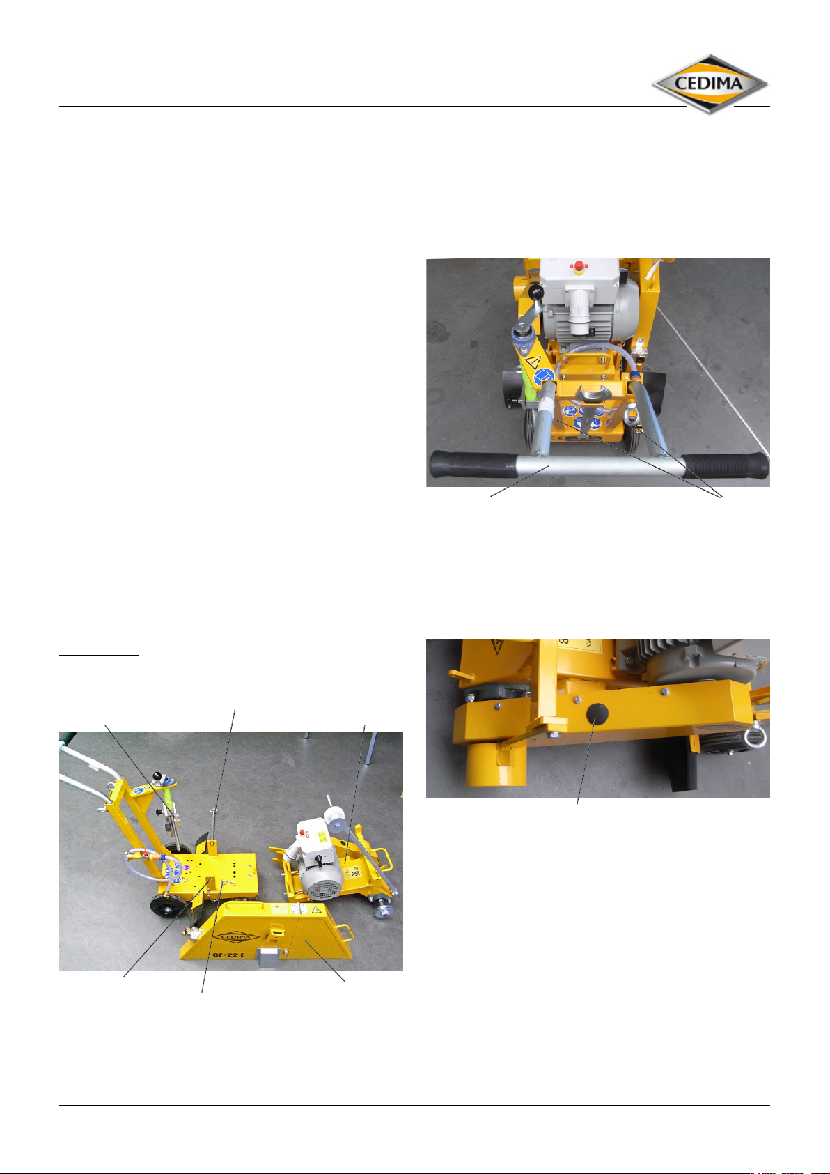
4.1.2 Adjusting the push handle
Release the ring bolts and pull out the push handle ap-
propriate to your height until you can move the joint cutter
comfortably.
Lock the push handle in the desired position by means of
the ring bolts.
Push handle Eye bolts
Figure 4.2
4.1.3 Checking the V-belts tension
Check the tension of the V-belts daily!
– Proceed in reverse order to Assembling.
Arm extension of the
hight adjustment
Bearing of the trolley Blade guard
Spring cotter pin
Figure 4.1
Central bolt
Rocker with motor
and cutting shaft
V-belt cover with plug Figure 4.3
The tension of the V-belts is checked as follows:
Disconnect the joint cutter from the mains by pulling the
plug!
Remove the plug of the V-belt cover at a motor standstill.
The plug is located on top of the belt cover.
Check the now accessible V-belts through the control
opening by pressing the belts with your ngers. It should
only be possible to press the belts about 10 mm downwards. If they can be pressed further they need to retight-
en.
The tensioning and changing of the V-belts is described in
chapter “care and maintenance”.
• CEDIMA® • Technical Documentation • All rights reserved according to ISO 16016 • Changes serving technical progress reserved •
15
Page 16
4.2 Mounting the diamond saw blade
4.2.1 General information on mounting
The drive unit of motor and cutting shaft RPM are designed
to provide optimal conditions for cutting with CEDIMA®
diamond saw blades!
Choose the right kind of diamond saw blade for the material to be cut!
Observe the diameter of the shaft hole (spindle diameter)
and of the cutting shaft.
Please refer also to chapter “technical data and accessories”.
If the shaft hole diameter of your saw blade is larger, use an
appropriate reducing ring!
The maximum permissible saw blade diameter is 700 mm!
Detailed information about the proper saw blade types and
reducing rings are to be obtained from CEDIMA®!
CEDIMA® can not accept any warranty in case of incorrect
use of diamond saw blades!
Complaints concerning diamond saw blades supplied by
CEDIMA® can only be accepted if the diamond segments
show a minimum remaining segment height of 20 %!
Set-up and operation
Joint cutter CF•22 E
Spindle
Star knob screw
for locking
the spindle
Stopper
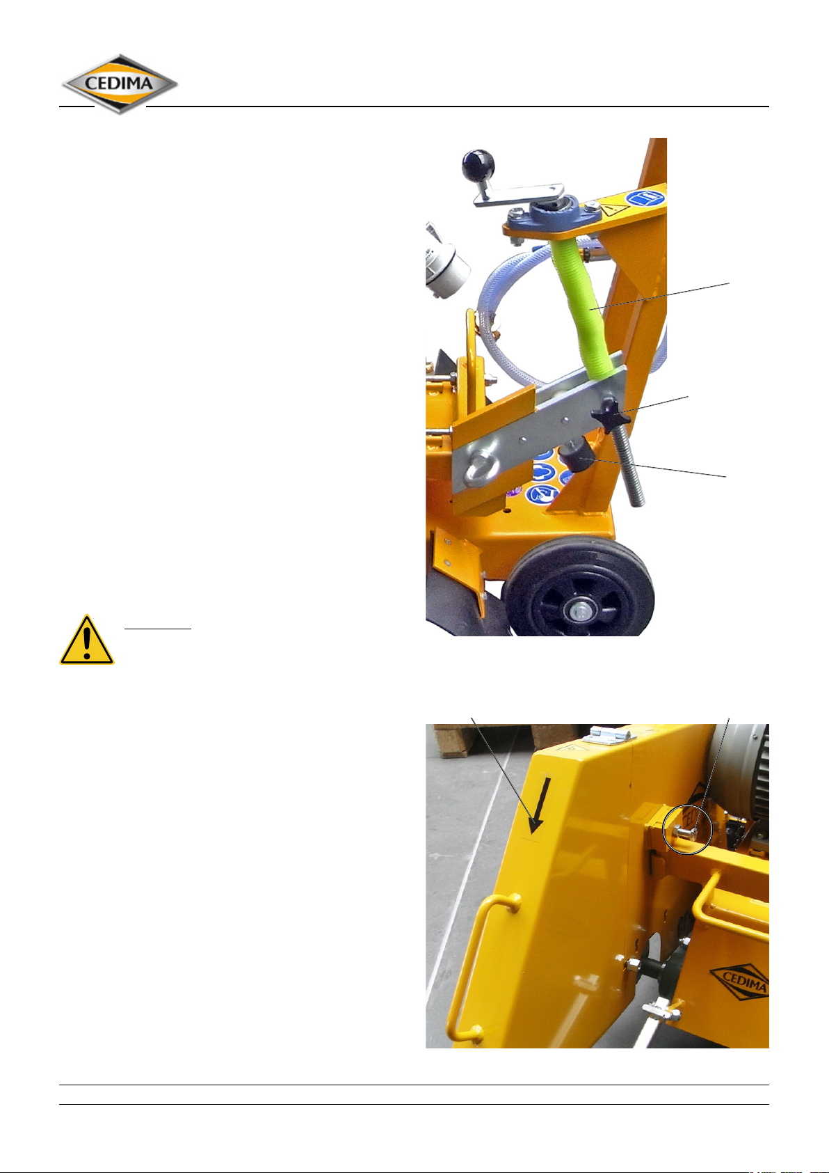
4.2.2 Lifting the cutting shaft
DANGER!
Make sure that the joint cutter can not be
started unintentionally by isolating the motor
from the power supply!
Loosen the star-knob screw which locks the lifting spindle.
Turn the spindle by means of the hand crank until the
blade arm reaches its maximum height. At the same time
the machine is braked by the stopper.
Figure 4.4
Loosen the clamping screw on the blade guard and lift it
upwards from the machine.
Directional arrow Clamping screw
Figure 4.5
• CEDIMA® • Technical Documentation • All rights reserved according to ISO 16016 • Changes serving technical progress reserved •
16
Page 17
Set-up and operation
Joint cutter CF•22 E
4.2.3 Mounting the saw blade
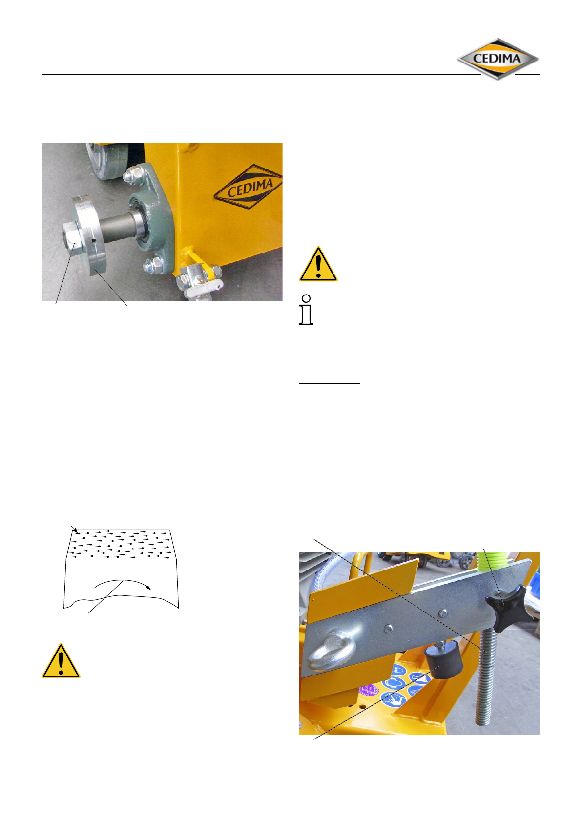
Loosen and remove the cutting shaft nut with the SW 36
spanner provided.
Cutting shaft Pressure ange
nut Figure 4.6
Remove the pressure ange.
Provide cleanliness of cutting shaft (thread) and blade
anges. Remove any dirt with a lint-free cloth.
The direction of rotation of the cutting shaft has to comply with the direction of rotation of the saw blade!
The sense of rotation of the cutting shaft is marked by an
arrow on the blade guard.
Imprinted on the saw blade is an arrow for the cutting
direction.
If this arrow is not visible, the cutting direction of the saw
blade can be determined as follows: During cutting, a “tail”
is formed behind the diamond; therefore, the diamond is
always in front of the “tail” (direction of rotation).
Diamond tail
Any damages/missing diamond segments as well as untrue
running exclude the use of the saw blade.
Mount the diamond saw blade and the clamping ange
on to the cutting shaft and tighten the cutting shaft nut
securely!
Make sure that the drive pin is properly inserted into the
clamping ange!
Replace the blade guard and tighten it with the clamping
screw.
After the cutting shaft nut has been tightened on the opposite side the cutting shaft protection must be assembled.
DANGER!
Using the joint cutter without the blade guard
is not allowed!
Diamond saw blades are designed to re-sharpen
themselves during cutting operation. They can be-
come blunt by frequent cutting in heavy steel armouring or in hard material, which is only slightly abrasive.
Blades can be re-sharpened by cutting in an abrasive material such as chalky sand stone or asphalt!
ATTENTION!
Operating the joint cutter without blade cover is not
allowed!
4.3 Aktuate the parking brake
To park the machine and prevent it from rolling away unintentionally, set the cutting shaft to the highest position
using the hand crank.
In this position, the left rear wheel is blocked.
Spindle Star knop screw for
locking the spindle
Segment
Direction of rotation
Figure 4.7
DANGER!
Check the sense of rotation of the diamond
saw blade, its true running and make sure it is
undamaged!
Before mounting the saw blade check it for possible damages.
Stopper Figure 4.8
• CEDIMA® • Technical Documentation • All rights reserved according to ISO 16016 • Changes serving technical progress reserved •
17
Page 18
Set-up and operation
Joint cutter CF•22 E
At strongly sloping terrain the machine must be additionally secured against rolling away.
Replace a worn stopper in time to preserve the braking
eect.
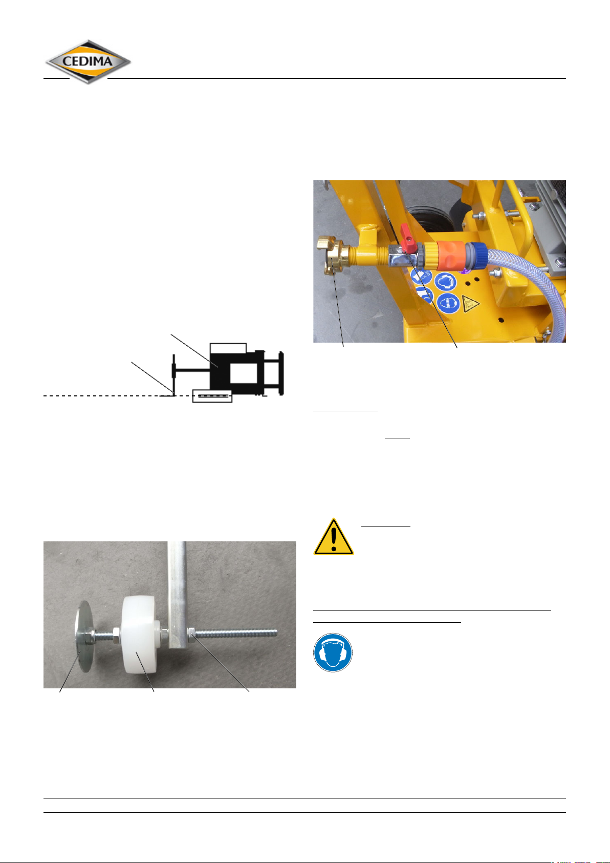
4.4 Adjusting and using the front pointer
The front pointer is adjustable mounted on the rocker with
motor of the joint cutter.
When fold down it allow the operator to cut precisely along
a marked line.
Alignment of the pointer is carried out with the motor
stopped and with the diamond saw blade tted.
If the pointer has been knocked out of adjustment or bent
during transportation, it can be realigned as shown in the
illustration below.
Joint cutter
Front pointer
Cord, ruler
Diamond saw blade
Figure 4.9
Stretch out a cord, a straight edge or a chalked line parallel
to the saw blade.
Loosen the locking nut and securing screw of the front
pointer rod.
Now dislocate the pointer disc to the left or right until the
saw blade is aligned in line with the pointer disc. Finally
retighten the screw.
4.5 Connecting the water supply
The joint cutter CF•22 E is provided with water via a GEKA
coupling.
The water shut-o valve which is located behind, permits
to stop or reduce the supply of water.
GEKA-water connection shut-o valve Figure 4.11
Only use water which is free from coarse pollution (free of
solids, clean) to prevent blockage of the cooling system!
ATTENTION!
Cutting tools which are designed for the wet-cutting
mode only, may never be operated without water! Loss of
segments will inevitably be the consequence!
4.6 Starting the motor
DANGER!
When starting the engine, the cutting shaft
with any mounted saw blade will start rotating immediately!
The joint cutter should only be moved to the operating
area when the saw blade is at standstill!
Transporting and moving the joint cutter with the saw
blade rotating freely is forbidden!
Ear protection must be worn!
Pointer disc pointer wheel threaded rod
with nut
Figure 4.10
• CEDIMA® • Technical Documentation • All rights reserved according to ISO 16016 • Changes serving technical progress reserved •
18
To start the motor in safety, lift the diamond sawing blade
from the surface to be cut (resp. out of the cut) by turning
the crank 2 turns by hand.
The motor is started via the star-delta reversing switch on
the control box.
Before starting, connect the power supply to the electric
motor. Make sure that you obey the relevant safety provisions for the operation of electrical machinery.
Page 19
Set-up and operation
Joint cutter CF•22 E
ATTENTION!
Connect the electrical connections properly!
Working on electrical mains and electric motors
may only be carried out by electricians or by persons under the
supervision of electrical specialists according to the electrotechnical rules. Observe the specic rules and regulations of
the country in question!
For use on a construction site, the connections must be on a
power supply according to IEC (EN) 61439 und 60364-7-704 a
building site power supply!
Pay attention to the relevant safety information for operating
electrical systems, e.g. DGUV 3 of BGHW, the respective VDE
specications and the relevant measuring (standard) e.g. EN
60 204-part 1!
ATTENTION!
Observe specications for connecting the mains power
supply cable!
The mains power supply cable, the cable drum must be
according to the connected values and be released for the
outer area!
Never connect with the mains power supply cable wound onto
the cable drum since power losses can occur on the joint cutter
due to the heat resistance!
From a cable length of 50 m losses in performance arise on the
joint cutter!
From a cable length of 100 m losses in performance increase
strongly!
The losses in performance can be almost completely compensated for by using appropriate cable cross sections:
Pay attention to the cross-section equivalent to the lengths of
the electric connections:
up to 20 m –> 5 x 4 mm²
up to 50 m –> 5 x 6 mm²
up to 100 m –> 5 x 10 mm²
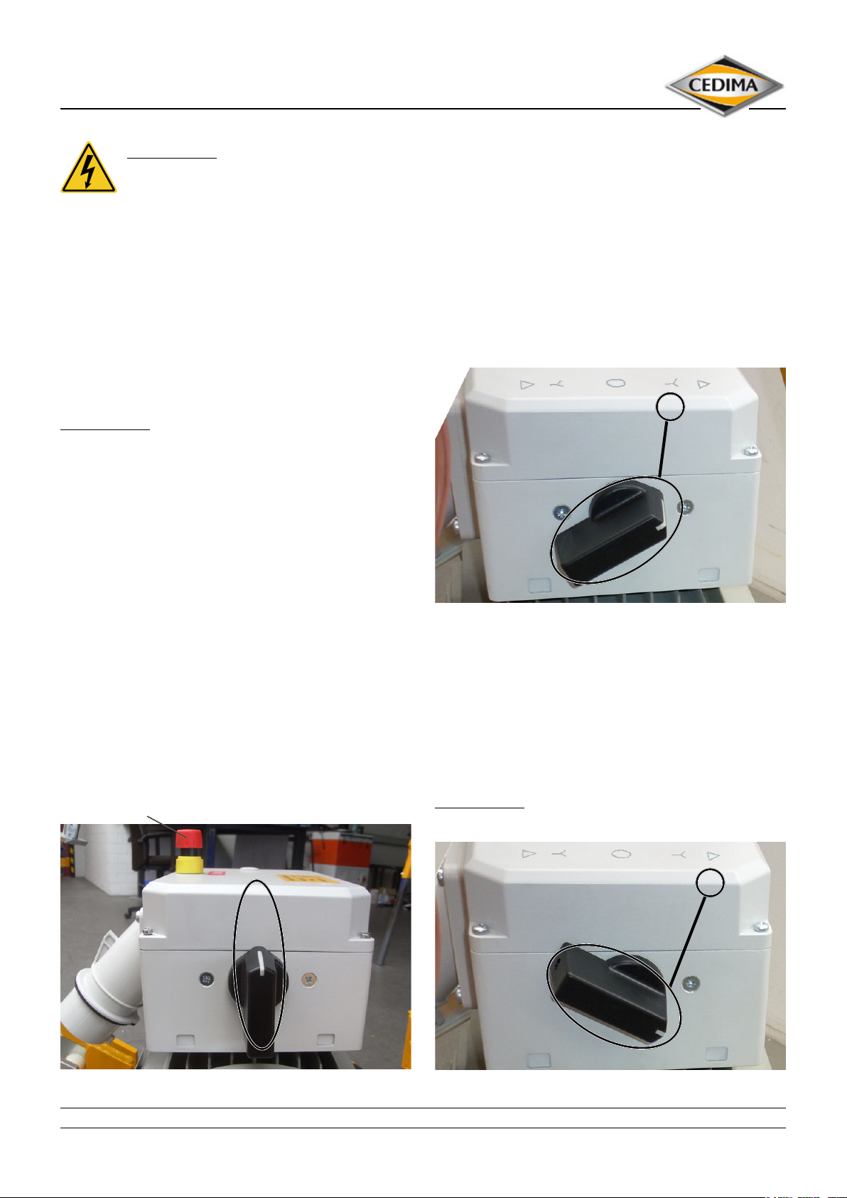
Emergency-stop button
The saw blade will start rotating on operating the motor
switch. Make sure that no danger might occur from the
rotating saw blade!
Turn the star-delta reversing switch right to Y position
until the saw blade begins to turn, then turn the star-delta
reversing switch left, back to 0.
The saw blade is slowly running down. Observe the rotational sense of saw blade. The rotational sense of the saw
blade must correspond to the direction indicated by the
arrow on the blade guard (the rotational sense of the ventilator wing must correspond to the arrow on the ventilator
cover).
∆ Y 0 Y ∆
Star-delta reversing switch switched in Y-position Figure 4.12a
When the rotational senses match, turn the star-delta
reversing switch again right to position Y. Wait until the
motor has reached the nal number of revolutions, then
turn the star-delta reversing switch further right to Δ.
If the direction of rotation of the saw blade is wrong, switch
the star-delta reversing switch to the left and, when the
nal speed is reached, swith it further to the left into the
position.
ATTENTION!
Only operate the machine in the Δ position!
Δ
∆ Y 0 Y ∆
∆ Y 0 Y ∆
CF-22 E switched o Figure 4.12b
• CEDIMA® • Technical Documentation • All rights reserved according to ISO 16016 • Changes serving technical progress reserved •
Star-delta reversing switch switched in ∆-Position Figure 4.12c
19
Page 20
Set-up and operation
Joint cutter CF•22 E
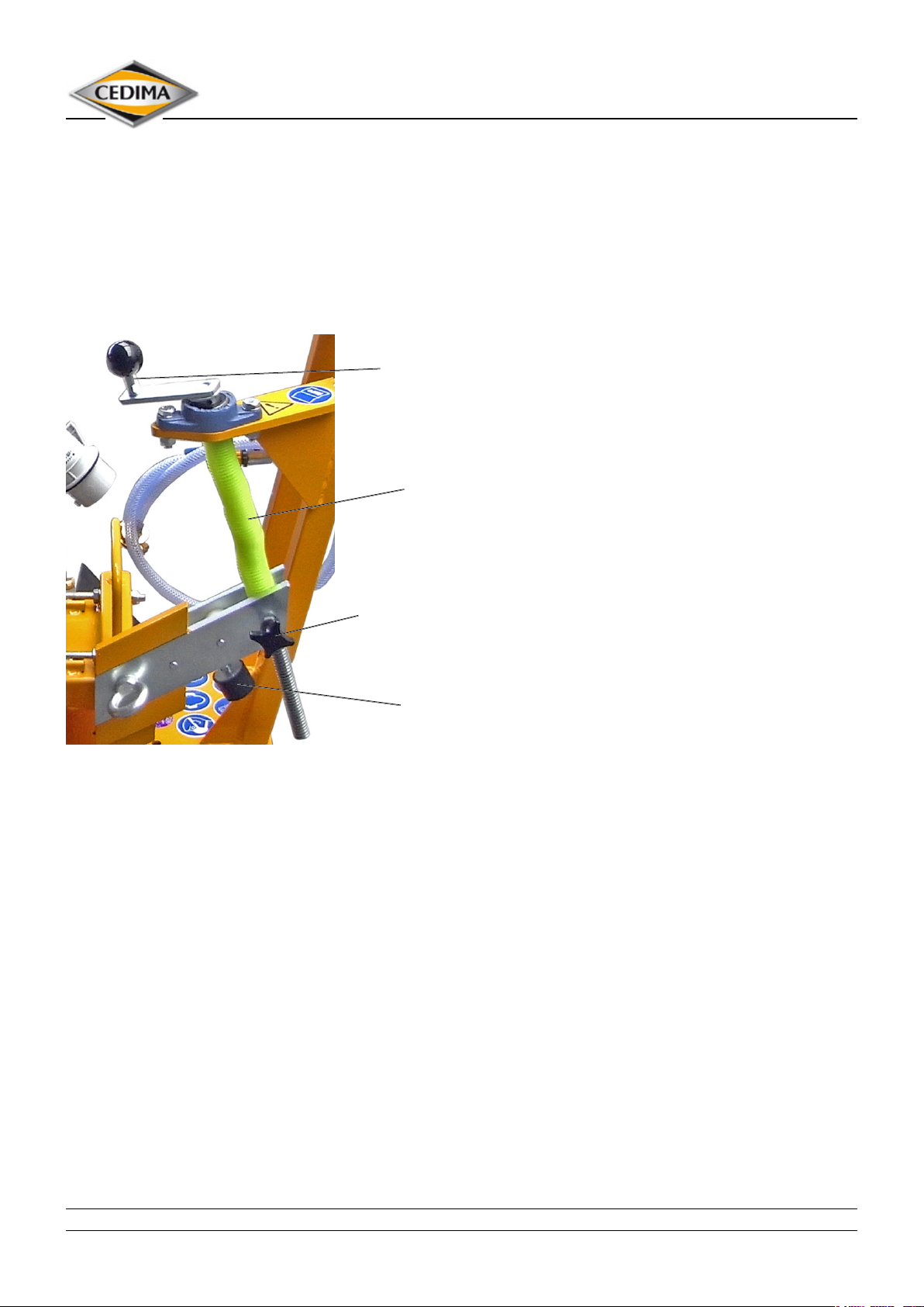
4.7 Adjusting the cutting depth
The cutting shaft respectively the diamond saw blade are
steplessly lowered and raised by means of the hand crank
with threaded spindle.
After lowering the diamond saw blade to the required
depth, the spindle ist xed against accidental adjustment
by means of the star knop screw.
Hand crank
Spindle
Star knob screw
for locking
the spndle
Stopper
Figure 4.13
4.9 Finishing cutting operations
• Move the joint cutter a little backwards in order to allow
the diamond saw blade to turn freely in the cut.
• Release the hand crank and raise the diamond saw blade
out of the cut. Keep the machine in its position. Now secure the hand crank against unintentional displacement.
• Activate the xing brake as described in section 4.3.
• Stop the water supply.
• Switch o the blade drive motor by putting the star delta
switch in to position “0”!
The joint cutter is additionally equipped with an emergency stop button which enables its quick separating of
the motor from the power supply in case of danger.
The emergency stop button is located on control box of
the star-delta reversing switch.
4.10 Replacing the diamond saw blade
The diamond saw blade is replaced:
– after complete wear of the diamond segments
– when the material to be cut changes.
Replacing the diamond saw blade is absolutely
necessary:
– if it is worn down unevenly
– if the diamond segments are damaged or broken o.
For mounting a new diamond saw blade please proceed as
described in section 4.2.
4.8 Performing the cutting work
• Align the joint cutter to the cutting line.
• Open the water shut-o valve and regulate the required
water quantity.
• Lower the diamond saw blade slowly to the desired cutting depth. Hold the joint cutter rmly!
• Proceed in several steps when deep cutting operatings
are to be performed.
Cutting depth per cut:
– Asphalte up to 10 cm
– Concrete up to 6 cm
• After lowering the saw blade to the desired cutting
depth tighten the cutting depth adjustment.
• The motor should continue to run at approximately
nominal speed.
• The cutting feed is generated by pushing the joint cutter
forward. Start moving the joint cutter slowly and keep
pushing forwards evenly! Choose the feed rate in such a
way so that the motor rpm is slightly reduced!
• CEDIMA® • Technical Documentation • All rights reserved according to ISO 16016 • Changes serving technical progress reserved •
20
4.11 Work to be performed after use
Carry out cleaning and maintenance work according to
chapter “care and maintenance”!
Page 21
Maintenance and care
Joint cutter CF•22 E
5.0 Maintenance and care
When carrying out maintenance and care work, follow the
“Basic safety instructions” in chapter 3 of this operating
manual!
• The joint cutter has to be cleaned before each maintenance!
• Care and maintenance work has to be carried out
according to the cycles described in chapt. 5.5! Also
check and if necessary change or adjust all wear parts
that have not specically been included in the listed
maintenance intervals.
Keep exactly to the care and maintenance intervals! This
will lengthen the life of your machine!
DANGER!
Risk of injury!
The joint cutter CF-22 E has to be switched OFF
when care and maintenance work is being carried out!
Switch o the blade drive motor! Disconnect the joint
cutter from the mains!
Secure the joint cutter against unintentional starting and
rolling o!
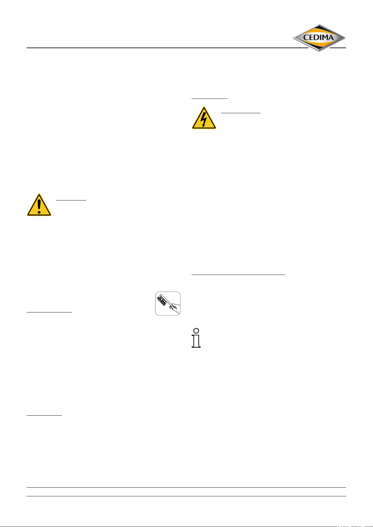
Wet cleaning
ATTENTION!
Do not use high-pressure cleaners respectively
steam cleaners!
For safety reasons, no water / cleaning liquid may penetrate the electric motor, plugs and switch box with the
star-delta reversing switch!
– Therefore, cover or seal all openings, casings, plug con-
nectors etc. which are at risk!
– Remove dirt and residues with a “gentle” jet of water and
a (not too hard) brush.
– Be especially careful at the critical parts (e.g. electric mo-
tor, switches,…)!
The electric motor as well as all electrical components may
not be cleaned with a water jet!
– To avoid them running dry, do not rinse the bearings
with water! The bearings are lubricated for life.
– After cleaning, covers or sealing materials are to be
removed completely!
Re-greasing, corrosion protection
5.1 Cleaning
Cleaning agents
– Do not use any aggressive cleaning agents
(solvents, acids or similar)
• High-pressure cleaners and aggressive cleaning uids, as
well as cleaning with uids of exceeding a temperature
of 30 °C are not allowed!
– Use lint-free cleaning cloths!
5.2 Cleaning procedure
Dry cleaning
– Remove dust and dirt with a lightly damp cloth!
– Remove stubborn crusty sediment with a (not too hard)
brush!
– After cleaning, provide the metallic sliding parts (spindle
g. 4.13) with a thin coating of grease (anti-rust protection) or corrosion protection oil! All other metal bearings
and movable machine parts should never run dry, but
slightly be greased with a thin lm of multi-purpose
grease and machine oil!
Excessive grease and oil promotes wear and tear
due to adhesive dust and dirt (slurry) clinging to the
machine!
– Check all connections and connecting elements be-
tween the components and re-tighten screw connections that may have become loose (see section 5.4)!
• CEDIMA® • Technical Documentation • All rights reserved according to ISO 16016 • Changes serving technical progress reserved •
21
Page 22
5.3 Maintenance and care of the motor
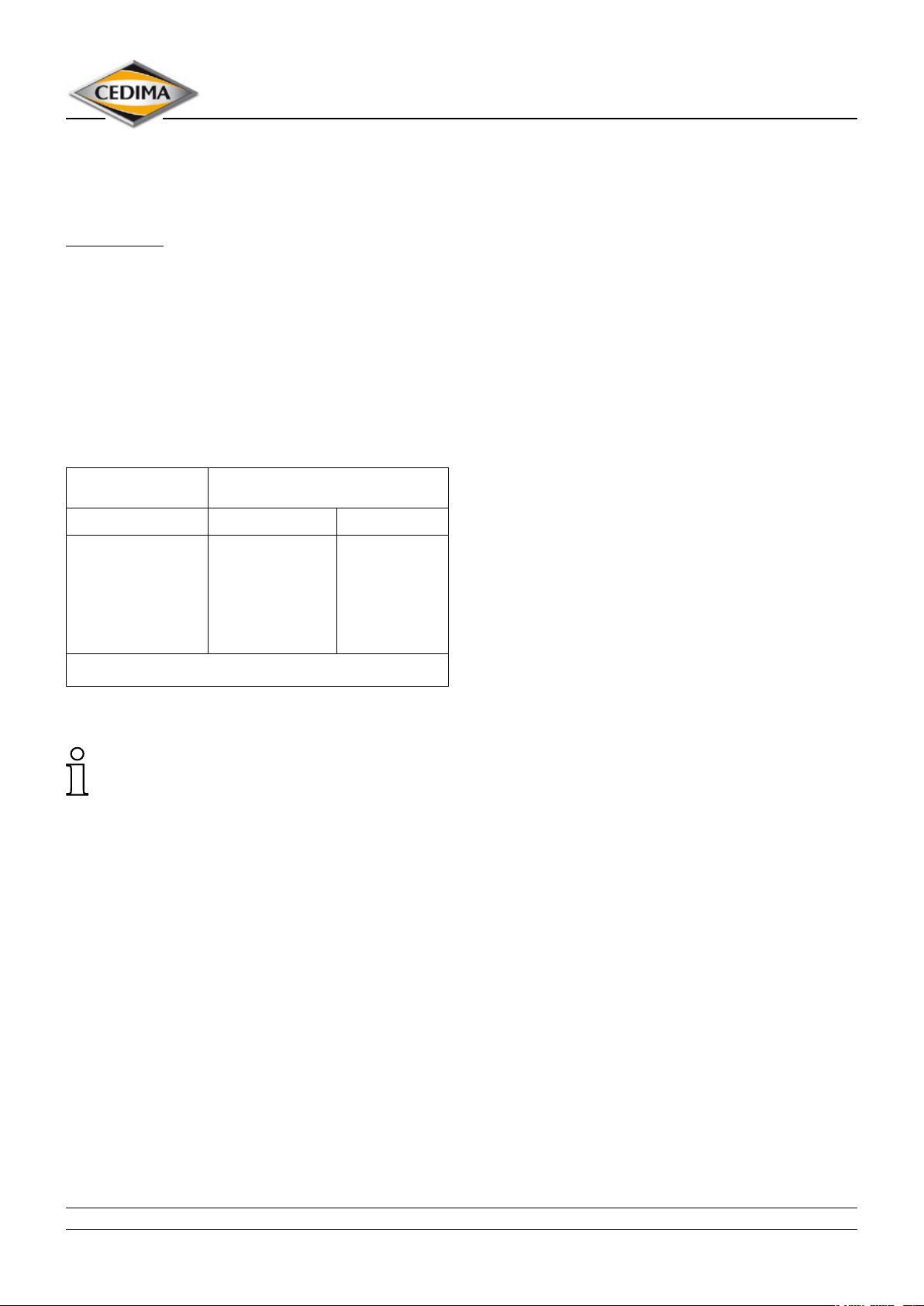
The electric motors does not need any special maintenance
and care. Stick to the safety and functional checks!
ATTENTION!
Stick precisely to the maintenance and inspection intervals (refer to section 5.5) and let the repair works be
carried out by a specialized workshop or by CEDIMA®.
Thus you extend the life time of your joint cutter.
5.4 Tightening torques
Coarse-pitch thread tightening torque [Nm]
acc. to DIN ISO 262 matching the strength class
8.8 10.9
Maintenance and care
Joint cutter CF•22 E
M 4 2.25 3.31
M 5 4.61 6.77
M 6 7.80 11.5
M 8 19.1 28.0
M 10 38.0 55.8
M 12 66.5 97.7
According to VDI directive 2230
Keep the safety and warning plates tted to the machine
always clean so that they are still legible after a longer
period.
• CEDIMA® • Technical Documentation • All rights reserved according to ISO 16016 • Changes serving technical progress reserved •
22
Page 23
Maintenance and care
Joint cutter CF•22 E
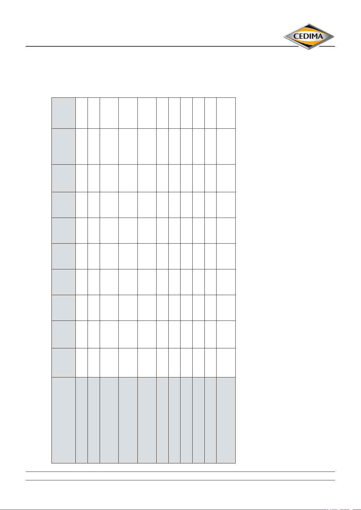
5.5 Maintenance intervals for the CEDIMA® joint cutter CF•22 E
In case of
damages
disturbances
Annually In case of
3 - 6
Weekly Monthly After
Initially
after
Every
working
After
nishing
Before
every
months
10 h
day
work
start-up
7 Legally required safety inspection
(see section 5.6)
2 3 4
5
7 7 7 7 7 4
4 Change, exchange
5 Retighten, adjust, change wear parts
1
3 1 3 3
1, 3 3 4
3, 6 1 4
3 1 4
3 3, 5 3 4 3 4
3, 7
3 3, 5 4
6 Change as required
Electrical system (switches, ...)
Tool holder (ange and saw blades
holder)
Tool
(diamond saw blade)
Control elements
(hand crank, ....)
V-belt
Threaded spindle
Motor housing
Motor
Parking brake
Reachable connecting elements
Entire machine
• CEDIMA® • Technical Documentation • All rights reserved according to ISO 16016 • Changes serving technical progress reserved •
(nuts, screws, ...)
h = Operating hours
1 Clean
2 Lubricate, grease, oil, corrosion protection
3 Control (visual inspections, function)
The description of the maintenance work can be found in the following and respective chapters of this operating manual!
The table can be updated at any time by CEDIMA® (for example appropriate technical requirements and developments)! Inform yourself by contacting CEDIMA®!
23
Page 24
Maintenance and care
Joint cutter CF•22 E
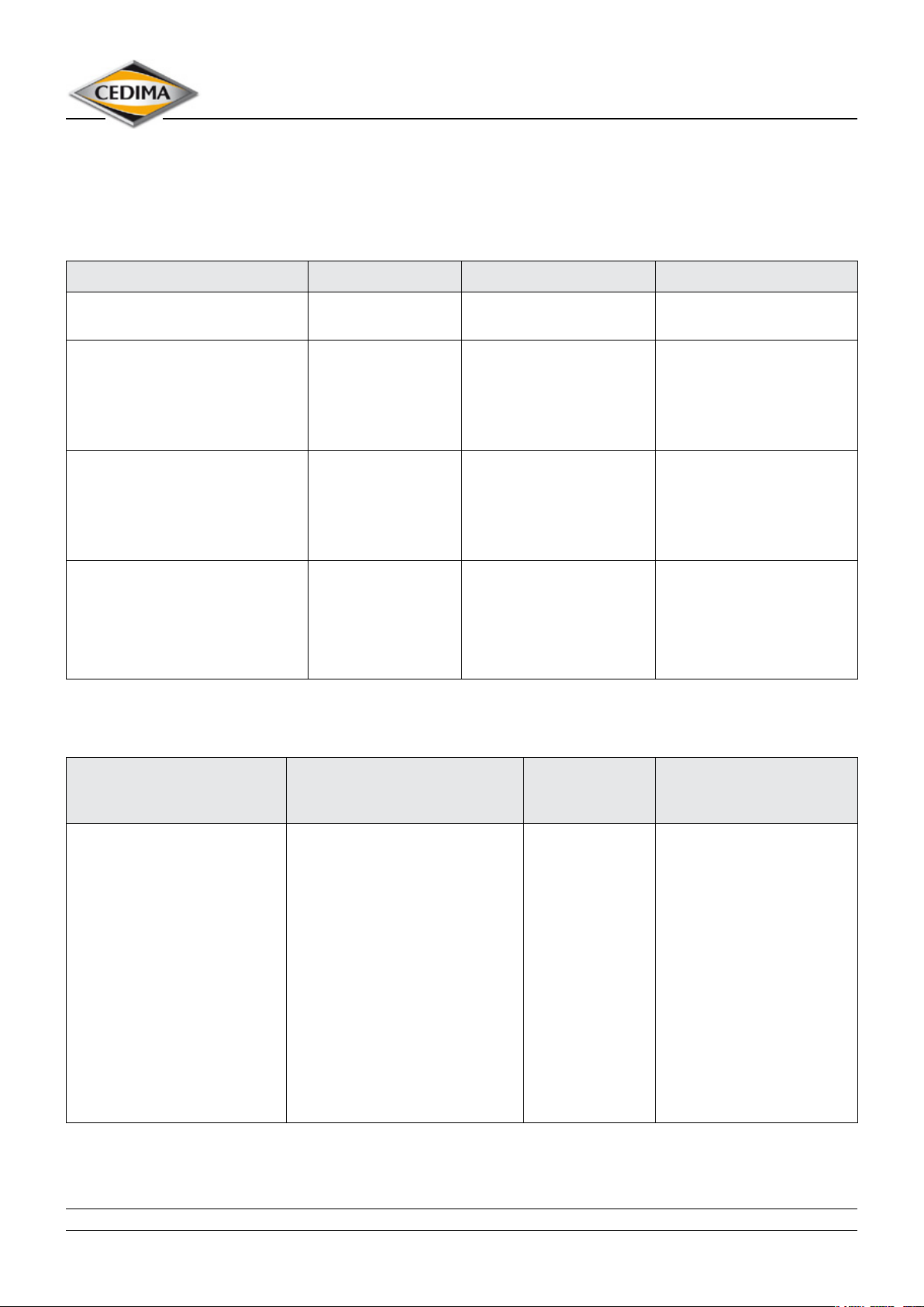
5.6 Safety checks of the electrical system according to DGUV regulation 3 § 5,
processing instruction paragraph 1 No. 2
Table 1 A: Repeated inspections of stationary electrical installations and equipment
Installation / Equipment Control period Type of control Inspector
electrical installations and
stationary equipment
electrical installations and
stationary electrical equipment
in “operating sites, rooms and
installations of special kind”
(DIN VDE 0100 Group 700)
protective measures with residualcurrent-operated protective
devices in non-stationary
installations
Fault current, residual current
device and circuit breaker
– in stationary installations
– in non-stationary installations
4 years checking for good
operational condition
1 year checking for good
operational condition
1 month eectivity electrical specialist or
checking for faultless
function by releasing the
checking device
6 months
every working day
electrical specialist
electrical specialist
electro-technical trained
person, using suitable
measuring and control
instruments
operator
Table 1 B: Repeated inspections of non-stationary electrical installations and equipment
Installation / Equipment Control period
standard values and maximal
values
– non-stationary electrical
equipment (if used)
– extension cables and
connecting cables with sockets
or plugs
– connection cables with plugs
– mobile cables with plugs and
sockets
For more concrete specications, refer to “rules for safety and health protection - selection and operation of electrical
installations and operating equipment on building sites“ (BGI 608).
• CEDIMA® • Technical Documentation • All rights reserved according to ISO 16016 • Changes serving technical progress reserved •
as a standard value every
6months, on building sites
3 months*).
Obtaining a margin of error
< 2 %, the control period can be
extended.
Maximum values:
On building sites, in production
facilities and work shops or
under similar conditions, one year
in oces or under similar
conditions, two years.
Type of control Inspector
checking for
good operational
condition
electrical specialist, when
using appropriate measuring
instruments also electrotechnically trained persons
24
Page 25
Maintenance and care
Joint cutter CF•22 E
5.7 Maintenance work
ATTENTION!
Observe the safety instructions of this operating manual
and all safety notes of attachments supplied with the
joint cutter!
ATTENTION!
Only use genuine parts!
Only by using genuine parts or parts (spare parts) approved
by CEDIMA® the operational safety of the CF•22 E can be
guaranteed.
5.7.1 Adjusting the tension of the V-belts
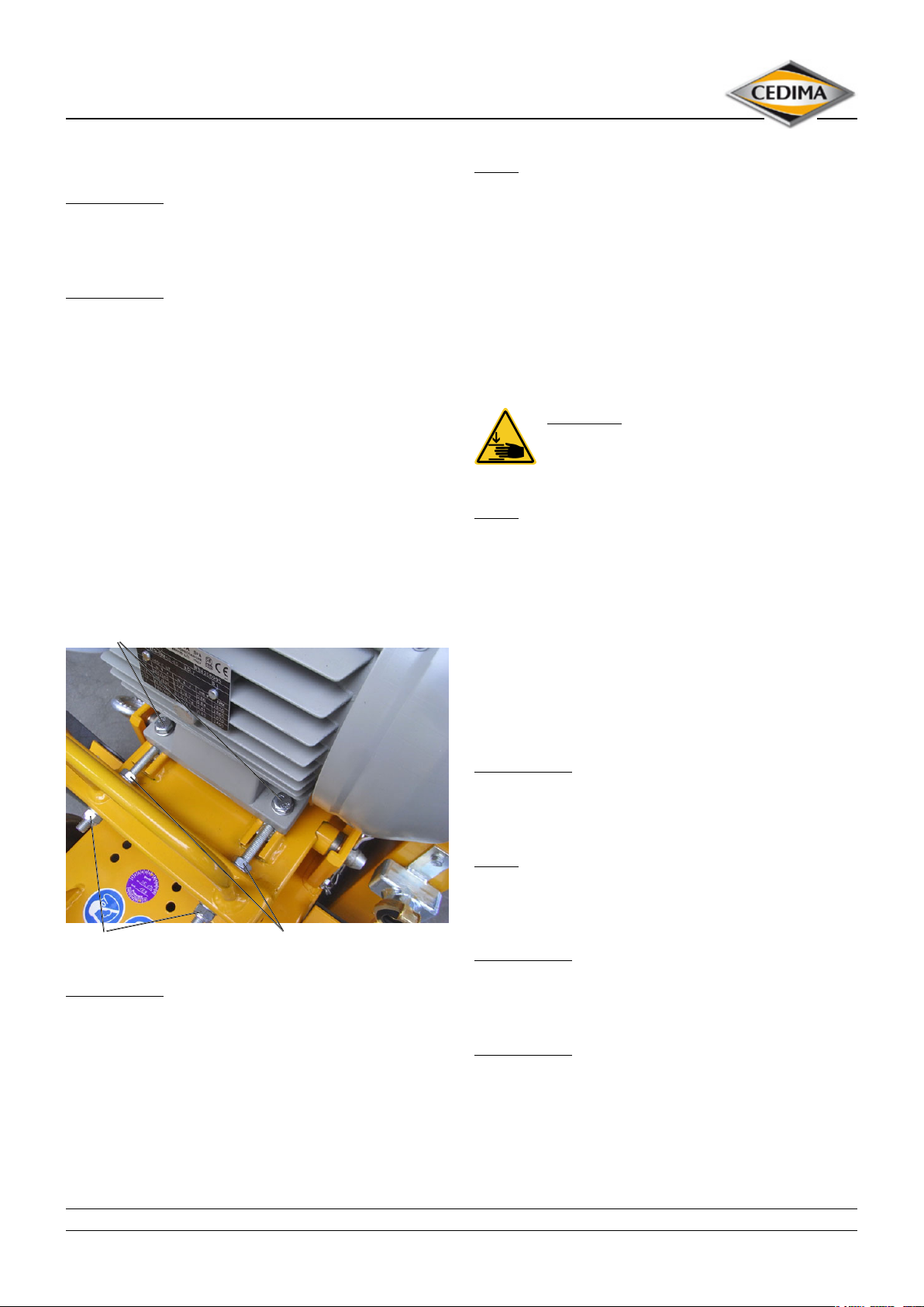
For tensioning the V-belts slightly loosen the two motor xing screws (g. 5.1). Pull the motor backwards with the helb
of the two tensioning screws mounted on the rear side of
the motor. While doing this, check the tension of the belts.
After the correct belt tension has been achieved, retighten
the lock nuts of the tension screws and the motor xing
screws.
Motor xing screws
NOTE
An even tightening of the clamping nuts can be obtained by
turning the nuts alternately each one turn!
– Check the tension of the V-belts (refer to section 4.1.3).
5.7.2 Changing the V-belts
The V-belts should and/or have to be replaced, when
further tensioning is no more possible and when they are
damaged (frayed, porous, …).
DANGER!
Risk of jamming and crushing during changing of the V-belts! Watch out for hands and
ngers!
NOTE
The belts shoud always be changed together, so a equally
tensioning and power transfer is possible.
Depending on the right or left cutting side, dismantle the
blade guard or the cutting shaft protection rst (g. 4.3).
After dismounting the V-belt cover (g. 4.3) the V-belt drive
is exposed.
Relax the V-belts as described in sect. 5.7.1, remove the old
belts and place the new.
Tighten the cutting shaft V-belts and mount the V-belt
cover and the blade guard resp. cutting shaft protection.
Clamping nut Lock nut
Figure 5.1
ATTENTION!
Tighten the nuts of the clamping screws evenly!
Unevenly tightened clamping nuts might lead to canting of
the motor suspension plate and consequently of the motor
and V-belt pulleys on the motor shaft.
The V-belts are running at the edges of the V-belt pulleys and
wear more quickly. A sudden rupture with negative consequences for the diamond saw blade and the motor cannot be
excluded!
ATTENTION!
Do not use any sharp or pointed objects for changing the
V-belts in order to prevent damages that might destroy
the V-belts.
NOTE
Turn the pulleys of the cutting shaft and the motor and move
the V-belts diagonally across the pulley grooves until all Vbelts are parallel.
ATTENTION!
Do not overstretch the V-belts (1,5% wear limit)! The
V-belt can break and the cutting shaft bearings and
motor bearing will be destroyed otherwise.
ATTENTION!
New V-belts have to be checked for correct tension and,
if necessary, be retensioned at least after 10 operating
hours!
• CEDIMA® • Technical Documentation • All rights reserved according to ISO 16016 • Changes serving technical progress reserved •
25
Page 26
Maintenance and care
Joint cutter CF•22 E
5.8 Transporting the joint cutter CF•22 E
DANGER!
Risk of injury! The joint cutter must always be
switched o before transport, secured against
unexpected restarting and against rolling away!
Disconnect the mains power connection, pull out
the mains plug!
• Uncouple the external compressed water hose and drain
the cooling and ushing system completely!
• Dismount the diamond saw blade!
Do not transport the joint cutter with the diamond saw
blade mounted!
• Transport the joint cutter upright and horizontally!
• Swivel up the front pointer!
• Lower the cutting shaft up to the stop!
• Push completely in the push handle and secure.
ATTENTION!
The push handle is not designed for transport by crane!
• Pay attention on the rm seat of all joint cutter components (tools,...).
• Use the two push handle pipes and the rocker for lashing!
• Dismantle the joint cutter in the appropriate (3) parts
(see sect. 4.1.1).
Check all connection, attachment elements and modules
after transport for rm and correct seat!
5.9 Longer periods out of service/storage
• Note the above-mentioned points for transport
• Observe maintenance intervals and carry out maintenance work!
• Release the tension of V-belts!
• Turn the cutting shaft (motor) roughly once a month (by
hand) through some revolutions!
• Actuate functions roughly once a month!
• Relieve the wheels (protect the base of the tire) by supporting the joint cutter frame with suitable pieces of
wood!
• Store the joint cutter in a dry, frost-free and dust-proof
place and also protected against extreme sunlight, temperatures (uctuations) as well as vibrations and other
negative physical and chemical eects!
• Check that all of the screws and assemblies are correctly
seated (rmly)!
• CEDIMA® • Technical Documentation • All rights reserved according to ISO 16016 • Changes serving technical progress reserved •
26
Page 27

Maintenance and care
Joint cutter CF•22 E
6.0 Taking back / disposal of the equipment
CEDIMA® commits to take the joint cutter CF•22 E back for disposal.
The joint cutter is to be delivered free of charge at CEDIMA® or at a point of acceptance appointed by CEDIMA®.
• CEDIMA® • Technical Documentation • All rights reserved according to ISO 16016 • Changes serving technical progress reserved •
27
Page 28
Trouble shooting, what if . . . ?
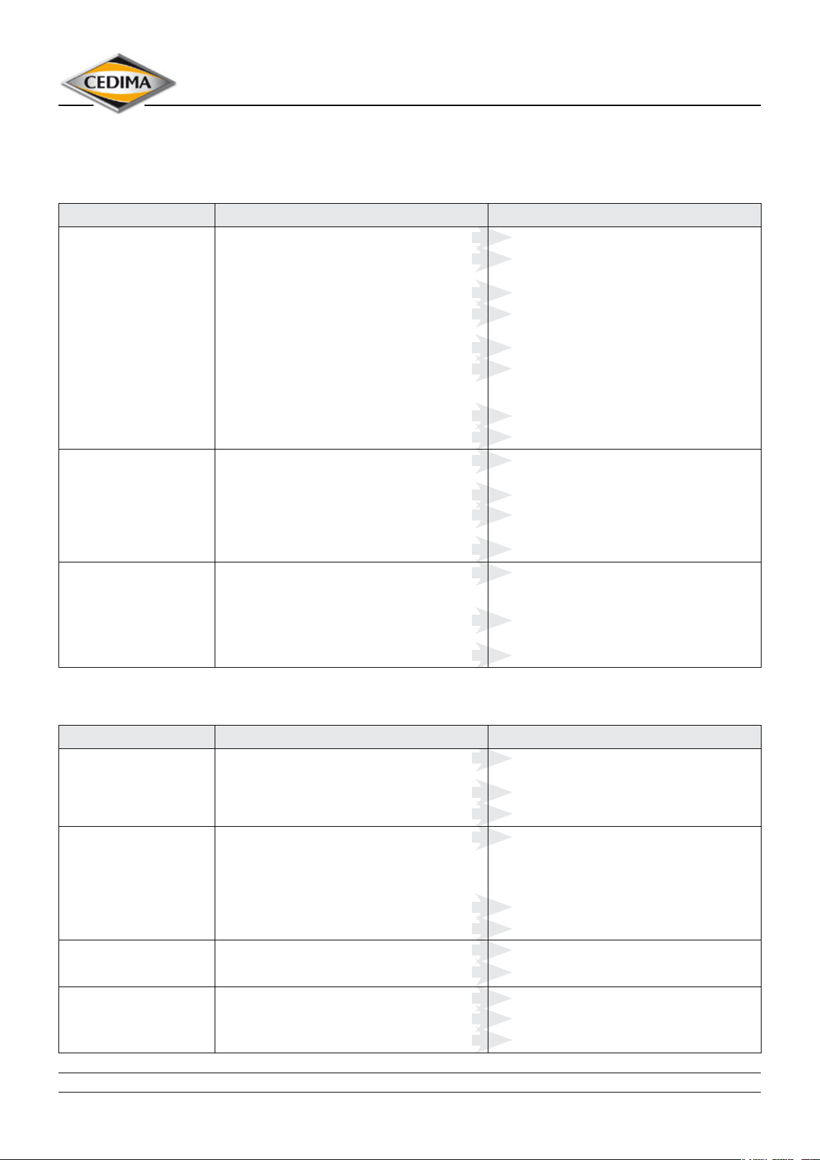
7.0 Troubleshooting at the joint cutter CF•22 E
7.1 Problems when starting (engine)
Problem Possible cause Remedy
The motor does not start The network cable is not attached properly
Network cable, plug connector, socket defective
Star-delta reversing switch is defective
Loosened electric connection in the electric system
The motor is defective
Cutting shaft blocked,
cutting shaft with the saw blade not lifted from the
ground or out of the cut
The power network fuse(s) have triggered
The motor has not yet been cooled o after overloading
No power available when
cutting,
The network cable is the wrong size, too long,
cable drum coiled up
The power supply network is not adequate
Star-delta reversing switch not “started through”, motor
in still in Y-mode
The motor does not maintain its rotational speed
Attach the network cable properly
Check the network cable, plug connector, socket and
replace it if necessary
Check the star-delta switch and replace it if necessary
Have the complete electrical system checked by an
electrician
Check the motor and replace it if necessary
Check for ease of movement of the cutting shaft
lift the cutting shaft (saw blade) from the ground, out of
the cut
Remove the fault, reset the fuses
Leave the motor to cool down
Connect the respective network cable, keep the network
cable as short as possible, roll o the cable drum
Comply with specied connection values
Bring the star-delta switch further into the ∆ position
Check the motor, repair it / replace it if necessary
Joint cutter CF•22 E
The motor has stopped Too high cutting pressure (overload protection)
Motor overload switch defective
Damage in electrical system
Reduce the cutting pressure (feed rate, cutting depth)
resp. have the motor cooled down with freely rotating
saw blade
Have the switch checked by an electrician and, if
necessary, replace it
Have the electrical system checked by an electrician
7.2 Problems when cutting
Problem Possible cause
Cutting blade wobbling Diamond saws ange(s) is/are dirty, and/or defective
The cutting shaft nut has come loose
Poor saw blade tension
The saw blade has side and/or
radial run-out
Diamond segments come loose The saw blade is overheating Resolder the diamond segments
The saw blade is damaged, bent
The diamond saws ange(s) is/are dirty, and/or defective
The cutting shaft is bent and/or the bearing is defective
Remedy
Clean the diamond saw ange, check it and replace it if
necessary
Tighten the cutting shaft nut
Return the saw blade to the manufacturer
Have the saw blades realigned
Have the diamond segments resoldered onto anew
blade core
Use anew saw blade
Clean the diamond saws ange(s), replace
Replace the cutting shaft and/ or bearing
Optimise the cooling water feed
Excessive diamond segment
wear
The wrong type of saw blade is/are being used
The cutting shaft is bent
The saw blade is overheated
Use aharder type of saw blade
Replace the bearing and/or cutting shaft
Optimise the cooling water feed
• CEDIMA® • Technical Documentation • All rights reserved according to ISO 16016 • Changes serving technical progress reserved •
28
Page 29
Trouble shooting, what if . . . ?
Joint cutter CF•22 E
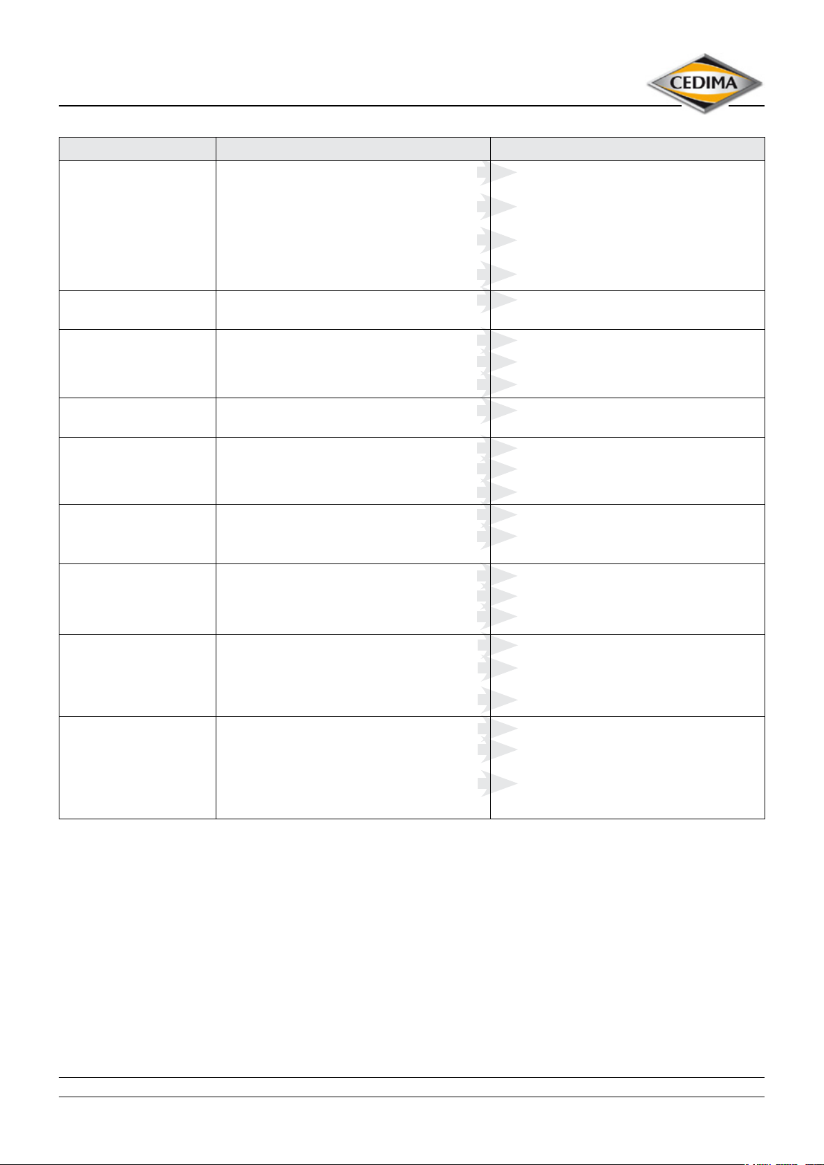
Problem Possible cause
The saw blade does not cut The saw blade is mounted backwards against the
Cracks in the saw blade steel
core
Cutting line is not optimal Poor saw blade tension (steel core)
The saw blade has rotated on
the cutting shaft
The saw blade remains under
load
The saw blade has become
coloured
direction of rotation
The saw blade is not matched to the material to be cut
(possibly it is too hard)
The saw blade is not matched to the machine power
output
Diamond segments are blunt
The saw blade is too “hard” Use a“softer” saw blade
The saw blade is overloaded
Diamond segments are blunt
Driving pin defective, missing Replace, insert the driving pin
The V-belt is slipping
The V-belt is defective (torn)
Driving pin defective, missing
The saw blade is overheated
The saw blade is subjected to excessive lateral friction
Remedy
Mount the saw blade according to the direction of
rotation of the cutting shaft
Use the correct type of saw blade
Use the correct type of saw blade
Resharpen the saw blade
Return the saw blade to the manufacturer
Reduce the feed rate (cutting depth)
Resharpen the saw blade
Tension the V-belt
Change the V-belt
Replace, insert the driving pin
Optimise the cooling water feed
Reduce the feed rate
Do not tilt the saw blade in the cut
Chang points on the saw
blade
Diamond segments show signs
of eccentric wear
Areduced or no cooling water
ow
The feed direction is not parallel to the saw blade
The saw blade is overloaded
Poor saw blade tension
The cutting shaft has shrunk
The mount for the saw blade is worn out (cutting shaft,
saw blade bore)
Excessive bearing play on the cutting shaft
The water supply is not optimal
The water hoses are blocked, defective, come o, kinked
The shut-o valve is blocked, defective, not opened
Do not tilt the saw blade in the cut
Reduce the advance speed
Return the saw blade to the manufacturer
Renew the cutting shaft
Turn out the saw blade mounting hole and adapt to the
correct diameter using aring
Replace the bearing or the cutting shaft
Adapt the pressurised water supply
Clean the water hoses, check them, connect them,
replace them if necessary
Clean, check, open the shut-o valve; replace it if
necessary
The problems and their possible causes are mainly due to natural wear and to incorrect use of the joint cutter or the
diamond saw blades!
Therefore you should read this operating manual thoroughly!
• CEDIMA® • Technical Documentation • All rights reserved according to ISO 16016 • Changes serving technical progress reserved •
29
Page 30

8.0 Terms of warranty
1. Complaints must be submitted without delay, however, within 14 days following the arrival of the
device at the latest. If this deadline has expired, or if the device complained about is put into operation
and used for work, then the device complained about shall be considered accepted and therefore free
of faults. Hidden defects must be reported in writing immediately after being discovered, however at
the latest within 6 months of the receipt of the device.
2. We guarantee the agreed usability of the device delivered by us for a period of 12 months, the term
beginning on the day the device arrives with the buyer. Irrespective of this, our obligation shall be
considered as fullled, as soon as the goods are despatched from our works/warehouse. In no case do
we assume a producers’ guarantee. The mandatory regulations of the law for product liability remain
untouched.
3. Wearing parts are subject to a limited warranty. Wearing parts are parts subject to operationrelated wear during proper use of the device. The rate of wear cannot be uniformly dened and diers
according to the intensity of use. The wearing parts must be adjusted, maintained and, if necessary,
replaced for the specic device in accordance with the manufacturer’s operating manual. Operationrelated wear is not a reason for claims to defects.
Wearing parts for the construction devices such as core drilling and sawing machines and special machinery as well as related general assemblies (if available):
– Feed and drive elements such as toothed racks,
gear wheels, pinions, spindles, spindle nuts,
spindle bearings, wires, chains, sprockets, belts
–
Seals, cables, hoses, packings, gaskets, plugs,
couplings and switches for pneumatic, hydraulic, water, electricity, fuel systems
– Guide elements such as guide strips, guide
bushes, guide rails, rollers, bearings, sliding
protection supports
– Clamping elements for quick release systems
– Flushing head seals
– Slide and roller bearings that do not run in an
oil bath
– Shaft oil seals and sealing elements
– Friction and safety clutches, braking devices
– Carbon brushes, collectors/armatures
– Consumable operating materials such as fuels,
lubricants, coolants etc.
– Easy-release rings
– Control potentiometers and manual switching
elements
– Securing elements such as dowels, anchors,
screws and bolts
– Fuses and lamps
– Bowden cables
– Commutators
– Diaphragms
– Spark plugs, glow plugs
– Parts of the reversing starter such as the star-
ting rope, starting pawl, starting roller and
return spring
– Sealing brushes, rubber seals, splash protection
cloths
– Filters of all kinds
– Drive and guide wheels/pulleys and associated
rubber tyres
– Cable wire protection elements
– Drive and travel wheels
– Water pumps
– Cut-material transport rollers
– Drilling, separating and cutting tools
– Energy storage devices
• CEDIMA® • Technical Documentation • All rights reserved according to ISO 16016 • Changes serving technical progress reserved •
30
Page 1 of 2 pages
Page 31

4. In case of a justi ed complaint, we can choose to repair the device and/or to provide a replacement
against return of the device. Replaced parts or devices become our property.
5. A complaint has to be led in writing, stating machine number, invoice number and date.
6. Improvements shall always be carried out at the delivery plant. Repair work requested by the buyer
to be carried out on his or a third party‘s premises, needs prior consent by us. The resulting costs of the
mechanic and any other assistants are borne by the buyer. The warranty expires, if the customer or any
other, unauthorized person, interfere with the purchased device.
7. If the replacement of assemblies or components by the buyer of others has been expressly arranged
with us, any possible recognition of the warranty case cannot be given by us until after the defective
parts have been returned to us and inspected by us.
8. According to the statutory regulations the buyer is only entitled to cancel a contract, if we refuse
improvements or the supply of replacements acc. to g. 4 even though a defect has been proven, or
a deadline that we have been given has elapsed unful lled. If only a minor defect has occured, the
buyer is merely entitled to an abatement of the purchase price, which in any other case is excluded.
We are not liable for compensation on account of a defect or damages subsequent to a defect, unless
these occur on account of an intention of a negligence whick we are responsible for.
9. No guarantee is assumed for damages that have arisen of the following reasons:
a) faulty installation,
b) improper use or overstressing,
c) permanent overload, leading to damages to coils or the windings of armatures,
d) extraneous causes, e.g. transport damages, climatic in uences or other natural phenomena,
e) use of integral or accessory parts that are not suitable/adjusted to our devices.
10. If there is reason for complaint about a diamond tool(s), this tool(s) must be removed from the
machine immediately! To protect your interest and to conduct a proper inspection, a segment height
of at least 20 % (of height in new condition) is required. Failure to observe this will lead to any claims
to replacement that you may have being avoided!
11. If warranty claims are satis ed by us, then this neither extends the warranty period nor does it
begin a new warranty period for the device. The warranty period for installed spare parts shall end no
sooner or later than the warranty period for the device.
12. Otherwise, our complete terms of sale and delivery apply.
13. The place of performance and venue for both parties is Celle, Germany.
CEDIMA® Diamantwerkzeug- und Maschinenbaugesellschaft mbH, Celle
January 2005
Page 2 of 2 pages
• CEDIMA® • Technical Documentation • All rights reserved according to ISO 16016 • Changes serving technical progress reserved •
31
Page 32

• DIAMOND SAW BLADES
for wet and dry cutting in concrete, reinforced concrete, asphalt, natural stone;
saw blade diameter from 110 to 2200 mm
• DIAMOND DRILL BITS
for wet and dry drilling in concrete, reinforced concrete, asphalt, natural stone;
drill bit diameter from 12 to 1200 mm
• DIAMOND TOOLS
grinding discs for hand and oor grinders, diamond saw wires,
chamfering discs, diamond saw chains, diamond segments
• JOINT CUTTERS
with petrol, diesel or electric motor, with or without automatic feed;
cutting depths from 120 to 900 mm
• CORE DRILL MACHINES
hand or drill rig machines with electric or hydraulic drilling motor;
drill diameter from 12 to 1250 mm
• WALL AND WIRE SAWS
electric, hydraulic and electro-hydraulic wall saws with a cutting depth
up to 730 mm; wire saw machines, circular saw
• TABLE SAWS
to cut tiles, general construction material or large-format stones;
cutting depth from 25 to 450 mm
• SPECIAL MACHINERY
reinforced concrete breakers, oor grinders, surface mills, crack mills,
brush machines, chain saws, hand saws, slurry separators
CEDIMA® Diamantwerkzeug- und
Maschinenbaugesellschaft mbH
Lärchenweg 3 • 29227 Celle/Germany
Tel. +49 (0) 5141-8 8540 • Fax +49 (0) 5141-8 6427
Internet: www.cedima.com • E-mail: [email protected]
 Loading...