

Page 1
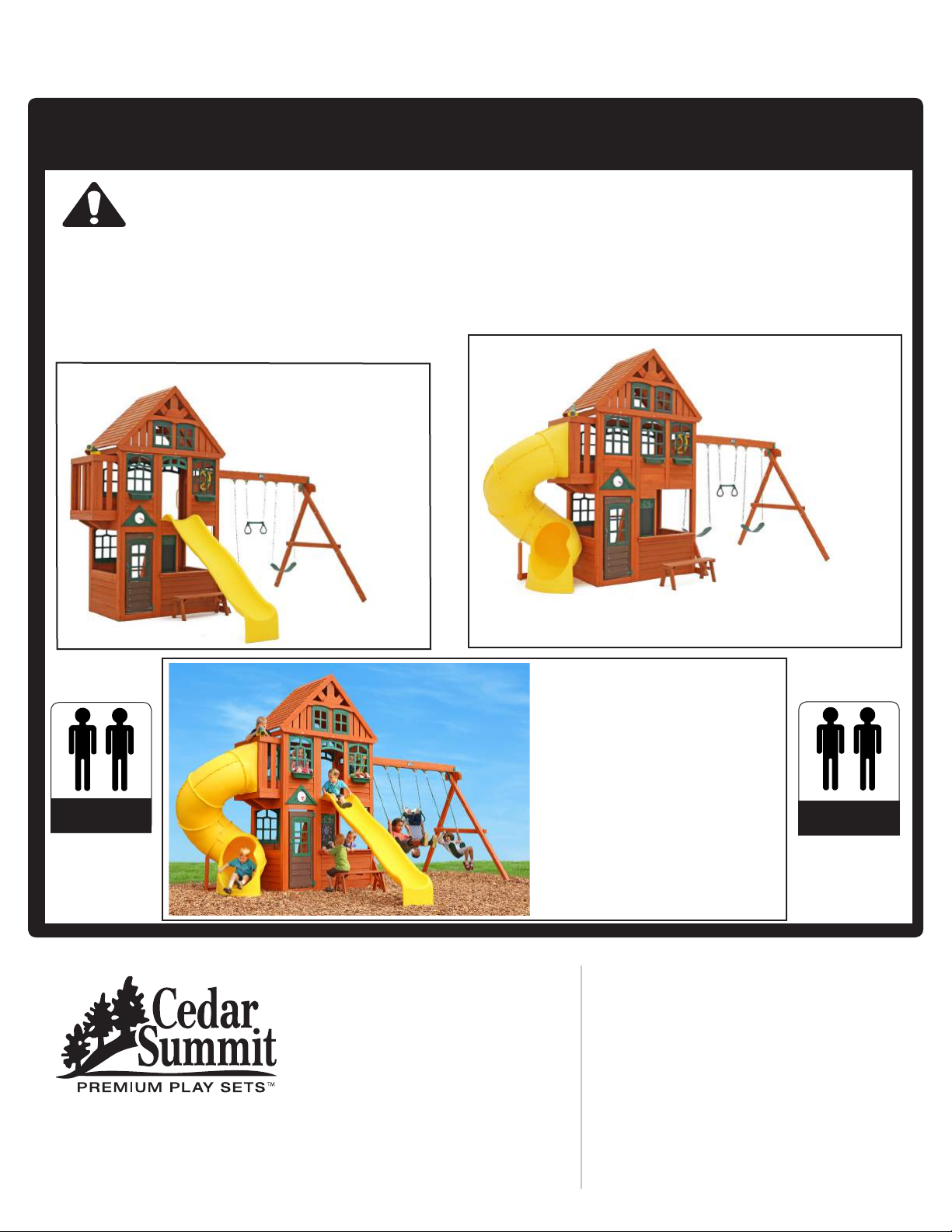
BROCKWELL – F24810/PRESTON – F24800/
TWIN MOUNTAIN LODGE – F25700Z
INSTALLATION AND OPERATING INSTRUCTIONS
To reduce the risk of serious injury or death, you must read and follow these instrucons.
WARNING
OBSTACLE FREE SAFETY ZONE -30’ 9” x 27’1” (9.37 x 8.23 m) area requires Protecve Surfacing. See page 3.
MAXIMUM VERTICAL FALL HEIGHT - 6’ 7” (2.01 m)
CAPACITY - 12 Users Maximum, Ages 3 to 10; Weight Limit 110 lbs. (49.9 kg) per child.
RESIDENTIAL HOME USE ONLY. Not intended for public areas such as mul-unit residences, schools, churches, nurseries, day cares or parks.
Keep and refer to these instrucons oen and give them to any future owner of this play set.
Manufacturer contact informaon provided below.
10 - 12 Hrs
FOR FORT & SWING
TWO PERSON
ASSEMBLY
BROCKWELL
Required:
53” Add On A (A24815)
53” Add On B (A24816)
53” Add On C (A24817)
53” Add On E (A24819)
53” Add On F (A24820)
PRESTON
Required:
53” Add On A (A24815)
53” Add On B (A24816)
53” Add On C (A24817)
53” Add On D (A24818)
53” Add On G (A24821)
TWIN MOUNTAIN LODGE
Required:
53” Add On A (A24815)
53” Add On B (A24816)
53” Add On C (A24817)
53” Add On D (A24818)
53” Add On E (A24819)
10 - 12 Hrs
10 - 12 Hrs
2 - 4 Hrs
2-4 Hrs
FOR FORT & SWING
FOR FORT & SWING
TUBE SLIDE
TWO PERSON
ASSEMBLY
Cedar Summit
c/o ©Solowave Design
375 Sligo Rd. West, PO Box 10
Mount Forest, ON Canada N0G 2L0
General Inquiries:
Regular Hours: 8:00am - 5:00pm EST
Peak Season (April - August):
8:00am - 7:00pm EST (Mon - Fri)
8:00am - 4:00pm EST (Sat & Sun)
Rev 01/30/20179404815
Toll Free: 1-877-817-5682
Email: [email protected]
Web Form/Line Chat: www.cedarsummitplay.com/contact-us
Table of Contents
Warnings and Safe Play Instructions ..........pg. 3
Protective Surfacing Guidelines. . . . . . . . . . . . . . . pg. 4
Instructions for Proper Maintenance .........pg. 5
About Our Wood – Limited Warranty .........pg. 6
Keys to Assembly Success ....................pg. 7
Part ID .......................................pg. 9
Step-By-Step Instructions ...................pg. 18
Installation of I.D./Warning Plaque ......Final Step
Page 2
ALTERNATE CONFIGURATIONS USING
BROCKWELL/PRESTON/TWIN MOUNTAIN LODGE
FOLLOW INSTRUCTIONS FOR BROCKWELL :
REQUIRED:
A24815 - 53’’ Add on A
F24825 - LANGDON RETREAT
F24826 - HUNTINGTON RESORT
A24816 - 53’’ Add on B
A24817 - 53’’ Add on C
A24819 - 53’’ Add on E
A24820 - 53’’ Add on F
A25230 - Adventure Tunnel
FOLLOW INSTRUCTIONS FOR BROCKWELL :
REQUIRED:
A24815 - 53’’ Add on A
A24816 - 53’’ Add on B
A24817 - 53’’ Add on C
A24819 - 53’’ Add on E
A24820 - 53’’ Add on F
A25230 - Adventure Tunnel
F24827 - CEDAR GROVE MANOR
F24828 -ORCHARD VIEW MANOR
Cedar Summit
c/o ©Solowave Design
375 Sligo Rd. West, PO Box 10
Mount Forest, ON Canada N0G 2L0
General Inquiries:
Regular Hours: 8:00am - 5:00pm EST
Peak Season (April - August):
8:00am - 7:00pm EST (Mon - Fri)
8:00am - 4:00pm EST (Sat & Sun)
FOLLOW INSTRUCTIONS FOR PRESTON :
REQUIRED:
A24815 - 53’’ Add on A
A24816 - 53’’ Add on B
A24817 - 53’’ Add on C
A24818 - 53’’ Add on D
A24821 - 53’’ Add on G
A25230 - Adventure Tunnel
FOLLOW INSTRUCTIONS FOR TWIN MOUNTAIN
LODGE :
REQUIRED:
A24815 - 53’’ Add on A
A24816 - 53’’ Add on B
A24817 - 53’’ Add on C
A24818 - 53’’ Add on D
A24819 - 53’’ Add on E
A25230 - Adventure Tunnel
Toll Free: 1-877-817-5682
Email: [email protected]
Web Form/Line Chat: www.cedarsummitplay.com/contact-us
Page 3
Warnings and Safe Play Instructions
CONTINUOUS ADULT SUPERVISION REQUIRED. Most serious injuries and deaths on playground equipment have occurred
while children were unsupervised! Our products are designed to meet mandatory and voluntary safety standards. Complying
with all warnings and recommendations in these instructions will reduce the risk of serious or fatal injury to children using
this play system. Go over the warnings and safe play instructions regularly with your children and make certain that they
understand and follow them. Remember on-site adult supervision is required for children of all ages.
WARNING
SERIOUS HEAD INJURY HAZARD
Installation over concrete, asphalt, dirt, grass, carpet
and other hard surface creates a risk of serious injury
or death from falls to the ground. Install and maintain
shock absorbing material under and around play-set as
recommended on page 3 of these instructions.
COLLISION HAZARD
Place play-set on level ground at least 6 feet from any
obstruction such as a garage or house, fences, poles,
trees, sidewalks, walls, landscape timbers, rocks,
pavement, planters, garden borders, overhanging
branches, laundry lines, and electrical wires. (See
OBSTACLE FREE SAFETY ZONE on cover)
CHOKING HAZARD/SHARP EDGES & POINTS
Adult assembly required. This product contains small
parts and parts with sharp edges and points. Keep parts
away from children until fully assembled.
WARNING LABEL
Owners shall be responsible for maintaining the legibility
of the warning labels.
STRANGULATION HAZARD
• NEVER allow children to play with ropes, clotheslines,
pet leashes, cables, chains or cord-like items when using
this play-set or to attach these items to play-set.
• NEVER allow children to wear loose tting clothing,
ponchos, hoods, scarves, capes, necklaces, items with
draw-strings, cords or ties when using this play-set.
• NEVER allow children to wear bike or sport helmets
when using this play-set.
Failure to prohibit these items, even helmets with chin
straps, increases the risk of serious injury and death to
children from entanglement and strangulation.
TIP OVER HAZARD
Choose a level location for the equipment. This can reduce
the likelihood of the play set tipping over and loose-fill
surfacing materials washing away during heavy rains.
DO NOT allow children to play on the play-set until the
assembly is complete and the unit is properly anchored.
WARNING – Safe Play Instructions
Observe capacity limitations of your play-set. See
front cover.
Dress children with well fitting and full foot enclosing
footwear.
Teach children to sit with their full weight in the center
of the swing seat to prevent erratic swing motion or
falling off.
Check for splintered, broken or cracked wood; missing,
loose, or sharp edged hardware. Replace, tighten and or
sand smooth as required prior to playing.
Verify that suspended climbing ropes, rope ladders, chain
or cable are secured at both ends and cannot be looped
back on itself as to create an entanglement hazard.
On sunny and or hot days, check the slide and other
plastic rides to assure that they are not very hot as to
cause burns. Cool hot slide and rides with water and wipe
dry prior to using.
Do not allow children to wear open toe or heel footwear
like sandals, flip–flops or clogs.
Do not allow children to walk, in front, between, behind
or close to moving rides.
Do not let children twist swing chains or ropes or loop
them over the top support bar. This may reduce the
strength of the chain or rope and cause premature failure.
Do not let children get off rides while they are in motion.
Do not permit climbing on equipment when it is wet.
Do not permit rough play or use of equipment in a
manner for which it was not intended. Standing on or
jumping from the roof, elevated platforms, swings,
climbers, ladders or slide can be dangerous.
Do not allow children to swing empty rides or seats.
Do not allow children to go down slide head first or
run up slide.
Page 4
Protective Surfacing - Reducing Risk of Serious Head Injury From Falls
One of the most important things you can do to reduce the likelihood of serious head injuries is to install shock-absorbing
protective surfacing under and around your play equipment. The protective surfacing should be applied to a depth that is suitable
for the equipment height in accordance with ASTM F1292. There are different types of surfacing to choose from; whichever
product you select, follow these guidelines:
Loose-Fill Materials
• Maintain a minimum depth of 9 inches of loose-fill materials such as wood mulch/chips, engineered wood fiber (EWF), or
shredded/recycled rubber mulch for equipment up to 8 feet high; and 9 inches of sand or pea gravel for equipment up to 5 feet
high. NOTE: An initial fill level of 12 inches will compress to about a 9-inch depth of surfacing over time. The surfacing will also
compact, displace, and settle, and should be periodically raked and refilled to maintain at least a 9-inch depth.
• Use a minimum of 6 inches of protective surfacing for play equipment less than 4 feet in height. If maintained properly, this
should be adequate. (At depths less than 6 inches, the protective material is too easily displaced or compacted.)
NOTE: Do not install home playground equipment over concrete, asphalt, or any other hard surface. A fall onto a hard surface
can result in serious injury to the equipment user. Grass and dirt are not considered protective surfacing because wear and
environmental factors can reduce their shock absorbing effectiveness. Carpeting and thin mats are not adequate protective
surfacing. Ground level equipment -- such as a sandbox, activity wall, playhouse or other equipment that has no elevated play
surface -- does not need any protective surfacing.
• Use containment, such as digging out around the perimeter and/or lining the perimeter with landscape edging. Don’t forget to
account for water drainage.
• Periodically rake, check and maintain the depth of the loose-fill surfacing material. Marking the correct depth on the play
equipment support posts will help you to see when the material has settled and needs to be raked and or replenished. Be sure to
rake and evenly redistribute the surfacing in heavily used areas.
• Do not install loose fill surfacing over hard surfaces such as concrete or asphalt.
Poured-In-Place Surfaces or Pre-Manufactured Rubber Tiles
You may be interested in using surfacing other than loose-fill materials - like rubber tiles or poured-in-place surfaces.
• Installations of these surfaces generally require a professional and are not “do-it yourself ” projects.
• Review surface specifications before purchasing this type of surfacing. Ask the installer/manufacturer for a report showing that
the product has been tested to the following safety standard: ASTM F1292 Standard Specification for Impact Attenuation of Surfacing
Materials within the Use Zone of Playground Equipment. This report should show the specific height for which the surface is intended
to protect against serious head injury. This height should be equal to or greater than the fall height - vertical distance between a
designated play surface (elevated surface for standing, sitting, or climbing) and the protective surfacing below - of your play equipment.
• Check the protective surfacing frequently for wear.
Placement
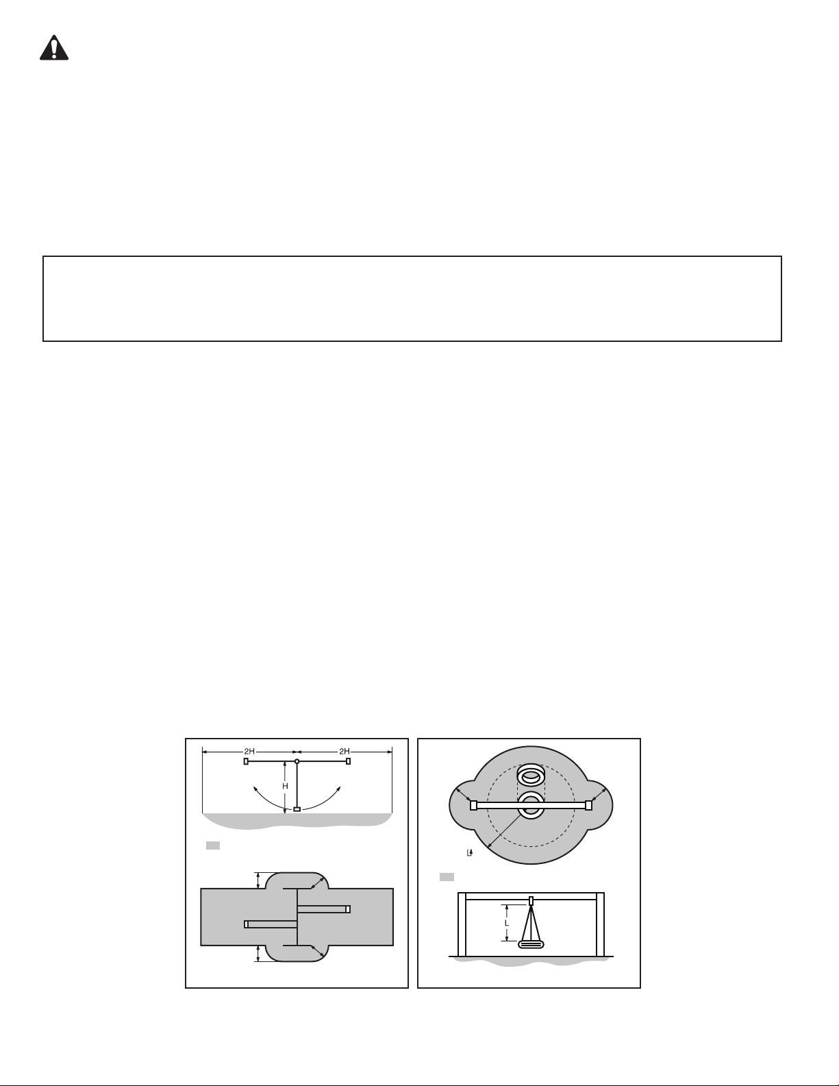
Proper placement and maintenance of protective surfacing is essential. Refer to diagram on front cover. Be sure to;
• Extend surfacing at least 6 feet from the equipment in all directions.
• For to-fro swings, extend protective surfacing in front of and behind the swing to a distance equal to twice the height of the top
bar from which the swing is suspended.
• For tire swings, extend surfacing in a circle whose radius is equal to the height of the suspending chain or rope, plus 6 feet in all directions.
6 ft. 6 ft.
Denotes Use Zone with Protective Surfacing
6 ft.
6 ft.
6 ft.
6 ft.
6 ft.
Denotes Use Zone with Protective Surfacing
Use Zone for Multi-Axis SwingsUse Zone for Single-Axis Swings
From the CPSC Outdoor Home Playground Safety Handbook. At http://www.playgroundregs.com/resources/CPSC%20324.pdf
Page 5
Instructions for Proper Maintenance
Your Cedar Summit Play System is designed and constructed of quality materials with your child’s safety in mind. As
with all outdoor products used by children, it will weather and wear. To maximize the enjoyment, safety and life of your
Play Set, it is important that you, the owner, properly maintain it.
Check the following at the beginning of the play season:
HARDWARE:
Check metal parts for rust. If found,
sand and repaint using a non-lead paint
complying with 16 CFR 1303.
Inspect and tighten all hardware. On
wood assemblies DO NOT OVERTIGHTEN as to cause crushing and
splintering of wood.
Check for sharp edges or protruding screw threads, add
washers if required.
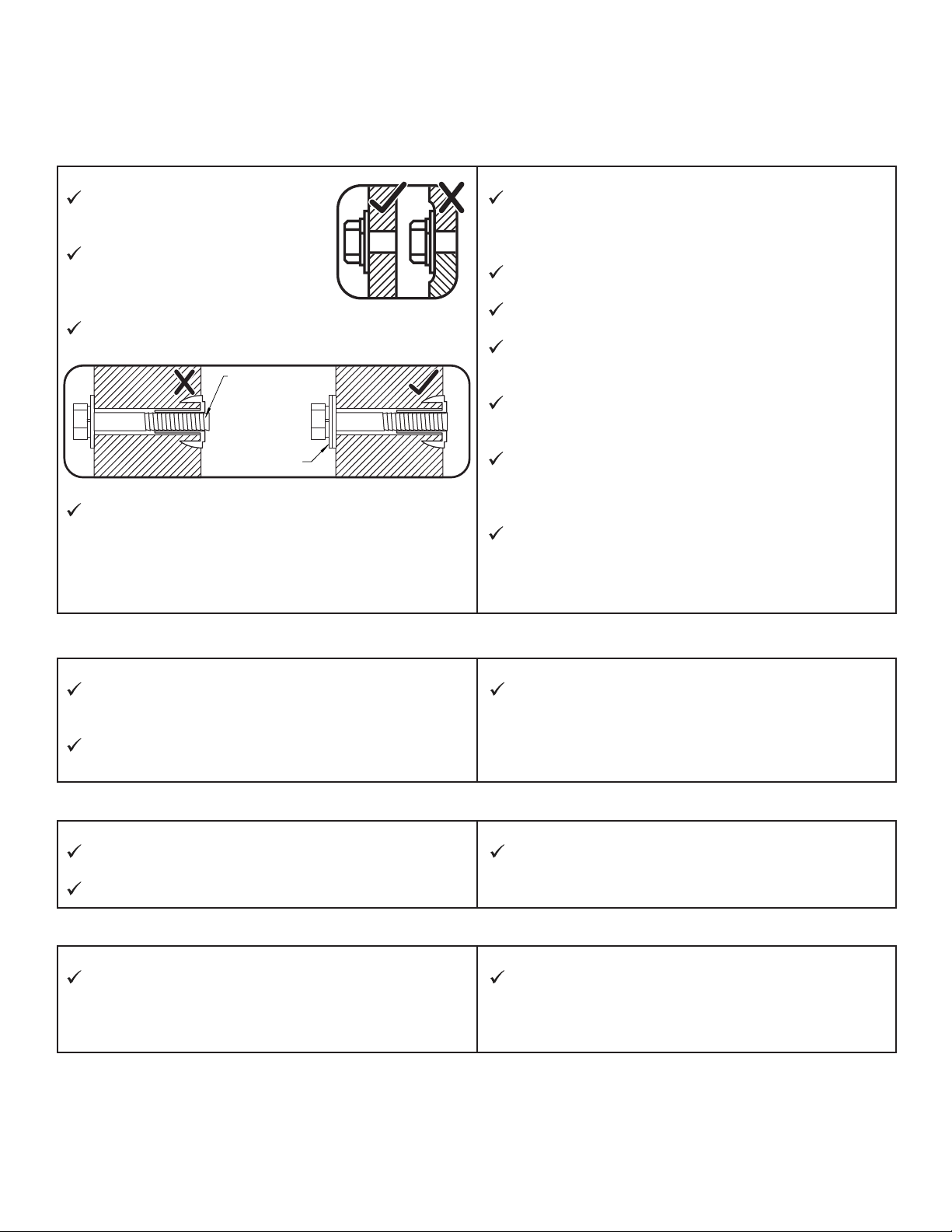
If Bolt protrudes
beyond T-Nut
Use an extra
flat washer
SHOCK ABSORBING SURFACING:
Check for foreign objects. Rake and check depth of loose
fill protective surfacing materials to prevent compaction and
maintain appropriate depth. Replace as necessary.
(See Protective Surfacing, page 3)
GROUND STAKES (ANCHORS):
Check for looseness, damage or deterioration. Should firmly
anchor unit to ground during use. Re-secure and or replace,
if necessary.
SWING HANGERS:
Check that bolts are secure and tight. Quick clips should be
completely closed and threaded clips screwed tight.
If squeaking occurs lubricate bushings with oil or WD-40®.
SWINGS, ROPES AND RIDES:
Reinstall if removed during cold season. Check all moving
parts including swing seats, ropes, chains and attachments
for wear, rust and other deterioration. Replace as needed.
Check that ropes are tight, secure at both ends and cannot
loop back as to create an entrapment.
WOOD PARTS:
Check all wood members for deterioration, structural
damage and splintering. Sand down splinters and replace
deteriorated wood members. As with all wood, some
checking and small cracks in grain is normal.
Applying a water repellent or stain (water-based) on a yearly
basis is important maintenance to maintain maximum life
and performance of the product.
Check twice a month during play season:
HARDWARE:
Inspect for tightness. Must be firmly against, but not
crushing the wood. DO NOT OVER-TIGHTEN.
This will cause splintering of wood.
Check for sharp edges or protruding screw threads.
Add washers if required.
SHOCK ABSORBING SURFACING:
Rake and check depth of loose fill protective surfacing
materials to prevent compaction and maintain appropriate
depth. Replace as necessary.
(See Protective Surfacing, page 3)
Check once a month during play season:
SWING HANGERS:
Check that they are secure and orientated correctly. Hook
should rotate freely and perpendicular to support beam.
If squeaking occurs lubricate bushings with oil or WD-40®.
SWINGS AND RIDES:
Check swing seats, all ropes, chains and attachments for
fraying, wear, excessive corrosion or damage.
Replace if structurally damaged or deteriorated.
Check at the end of the play season:
SWINGS AND RIDES:
To prolong their life, remove swings and store inside when
outside temperature is below 32°F/0°C. Below freezing,
plastic parts may become more brittle.
If you dispose of your play set: Please disassemble and dispose of your unit so that it does not create any unreasonable
hazards at the time it is discarded. Be sure to follow your local waste ordinances.
SHOCK ABSORBING SURFACING:
Rake and check depth of loose fill protective surfacing
materials to prevent compaction and maintain appropriate
depth. Replace as necessary.
(See Protective Surfacing, page 3)
Page 6
About Our Wood
Cedar Summit Premium Play Systems uses only premium playset lumber, ensuring the safest product for your children’s
use. Although we take great care in selecting the best quality lumber available, wood is still a product of nature and susceptible to
weathering which can change the appearance of your set.
What causes weathering? Does it affect the strength of my Play System?
One of the main reasons for weathering is the effects of water (moisture); the moisture content of the wood at the surface is
different than the interior of the wood. As the climate changes, moisture moves in or out of the wood, causing tension which can
result in checking and or warping. You can expect the following due to weathering. These changes will not affect the strength of
the product:
1. Checking is surface cracks in the wood along the grain. A post (4” x 4”) will experience more checking than a board (1” x 4”)
because the surface and interior moisture content will vary more widely than in thinner wood.
2. Warping results from any distortion (twisting, cupping) from the original plane of the board and often happens from rapid
wetting and drying of the wood.
3. Fading happens as a natural change in the wood color as it is exposed to sun-light and will turn a grey over time.
How can I reduce the amount of weathering to my Play System?
At the factory we have coated the wood with a water repellent or stain. This coating decreases the amount of water absorption
during rain or snow thus decreasing the tension in the wood. Sunlight will break down the coating, applying a water repellant or
stain on a yearly basis is important maintenance. (see your local stain and paint supplier for a recommended product)
Most weathering is just the normal result of nature and will not affect safe play and enjoyment for your child. However if you are
concerned that a part has experienced a severe weathering problem please call our consumer relations department for further assistance.
Complete and mail registration card to receive important product notications and assure prompt
warranty service.
5 Year Limited Warranty
Solowave Design warrants that this product is free from defect in materials and workmanship for a
period of one year from the original date of purchase. In addition, lumber is warranted for 5 years
against structural failure due to rot and insect damage. All other parts, such as hardware, swings, rides,
accessories, and slides carry a one-year warranty only.
This warranty applies to the original owner and registrant and is non-transferable.
Regular maintenance is required to assure the integrity of your Play System. Failure by the owner
to maintain the product according to the maintenance requirements may void this warranty. This
warranty does not cover any inspection cost.
This Limited Warranty does not cover:
• Labor for replacement of any defective item(s);
• Incidental or consequential damages;
• Cosmetic defects which do not affect performance or integrity;
• Vandalism; improper use or installation; acts of nature;
• Minor twisting, warping, checking, or any other natural occurring properties of wood that do not
affect performance or integrity.
Solowave Design products have been designed for safety and quality. Any modications made to
the original product could damage the structural integrity of the unit leading to failure and possible
injury. Solowave Design Inc. cannot assume any responsibility for modied products. Furthermore,
modication voids any and all warranties.
This product is warranted for RESIDENTIAL USE ONLY. Under no circumstance should a
Solowave Design Play System be used in public settings such as schools, churches, playgrounds,
parks, day cares and the like. Such use may lead to product failure and potential injury. Any and all
public use will void this warranty.
Solowave Design disclaims all other representations and warranties of any kind, express or implied.
This Warranty gives you specic legal rights. You may have other rights as well which vary from state to state or
province to province. This warranty excludes all consequential damages, however, some states do not allow the
limitation or exclusion of consequential damages, and therefore this limitation may not apply to you.
Page 7
Tools Required
Keys to Assembly Success
• Tape Measure
• Carpenters Level
• Carpenters Square
• Claw Hammer
• Standard or Cordless Drill
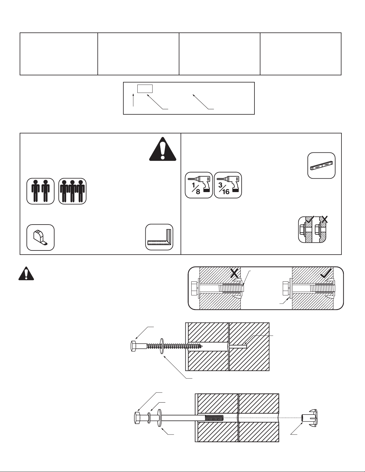
Part Identification Key
On each page, you will find the parts
and quantities required to complete the
assembly step illustrated on that page.
Here is a sample.
• #1, #3 Phillips or Robertson
bit or Screwdriver
• Ratchet(1/2”, 7/16” &
9/16” sockets)
• Open End Wrench
(1/2”, 7/16” & 9/16”)
• Adjustable Wrench
• 1/8” & 3/16” Drill Bits
2X 012 Post 2 x 4 x 83”
Quantity Key Number
Part Description,
Part Size
• 3/16” Hex Key
• 8’ Step Ladder
• Safety Glasses
• Adult Helpers
• Pencil
Key Number: The first two digits
represent the step number. The third
digit represents the piece. Note that if
the part is used in multiple steps then
the number only reflects the first step it
is used in.
Symbols
Throughout these instructions symbols are provided as important reminders for proper and safe assembly.
This identifies information that requires special
attention. Improper assembly could lead to an unsafe
or dangerous condition.
Use
Help
Measure
Distance
Use
Help
Check that assembly is square
before tightening bolts.
Use a measuring tape to assure
proper location.
Where this is shown, 2 or 3 people
are required to safely complete the
step. To avoid injury or damage
to the assembly make sure to get
help!
Square
Assembly
Check that set or assembly is properly level
before proceeding.
Pre-drill 1/8” & 3/16” Bit
Pre-drill a pilot hole
before fastening screw
or lag to prevent
splitting of wood.
This indicates time to tighten bolts, but
not too tight! Do not crush the wood.
This may create splinters and cause
structural damage.
Use
Level
Tighten
Bolts
CAUTION – Protrusion Hazard
Once the assembly is tightened, watch for exposed threads.
If a thread protrudes from the T-Nut, remove
the bolt and add washers to eliminate this condition.
Extra washers have been provided for this purpose.
Proper Hardware Assembly
Lag screws require drilling pilot
holes to avoid splitting wood. Only
a flat washer is required. For ease of
installation liquid soap can be used
on all lag-type screws.
For bolts, tap T-Nut into hole with
hammer. Insert the hex bolt through
lock washer first then flat washer then
hole. Because the assemblies need to
be squared do not completely tighten
until instructed. Pay close attention to
diameter of the bolts. 5/16” is slightly
larger than 1/4”.
Note: Wafer head bolts with blue lock
tight or a bolt with a Ny-Lok nut do
NOT require a lock washer.
Lag Screw
Hex Bolt
Lock
Washer
Flat
Washer
No Yes
If Bolt protrudes
beyond T-Nut
Use an extra
flat washer
Lag Assembly
Before mounting Lag
Screw, use factory drilled
holes as guides to drill 1/8”
pilot holes
Flat Washer
Bolt Assembly
T-Nut
(Hammer into place)
Do not crush wood!
Page 8
Your Key To Quick Assembly
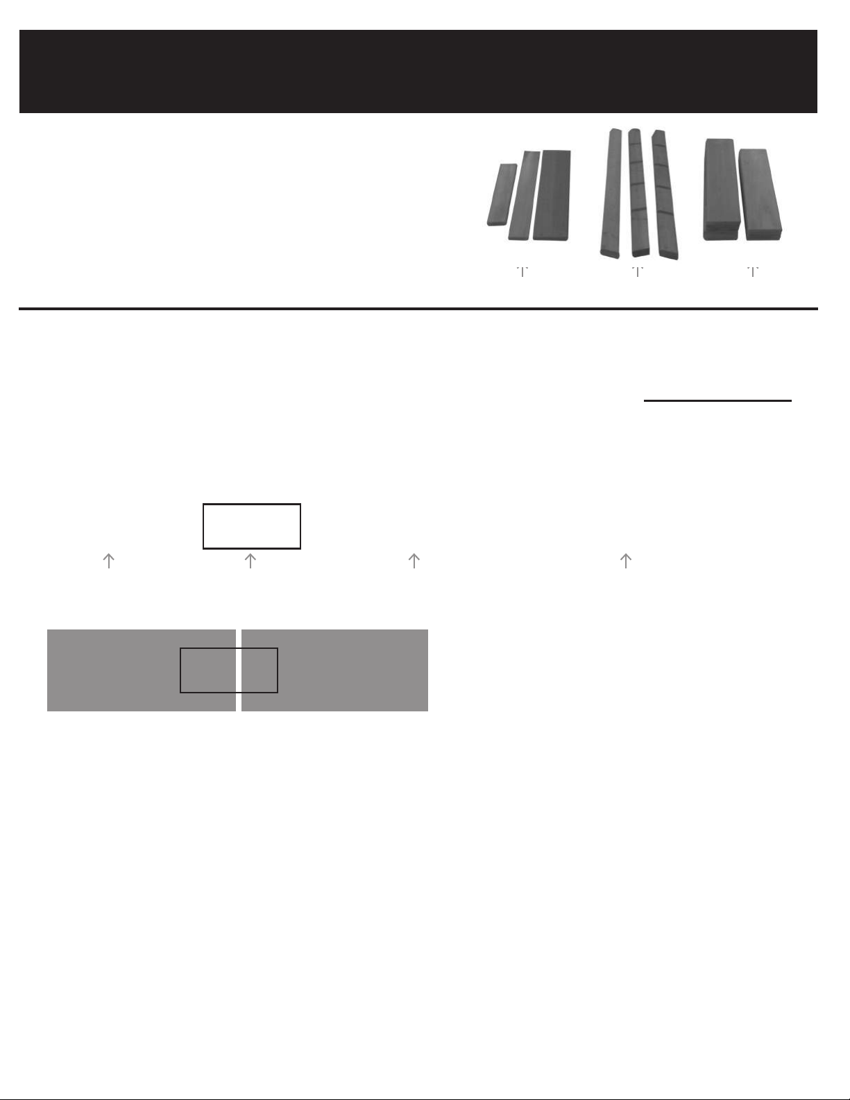
SORTING WOOD PARTS INTO
EACH ASSEMBLY STEP WILL
SAVE TIME!
Step Step Step
SAVE TIME - TIP #1:
Open each box with wood parts and look for the Key Number
stamped on the end of the wood part (see chart below). Sort
each wood part into the different assembly steps.
2X 012 Post 2 x 4 x 83”
Part Quantity Key Number
Step Number
(This is Step 1)
01 2
Order Listed
(The order the part is
SAVE TIME - TIP #2:
In addition to the key number stamp, you can also identify
the wood parts by using the Parts Identication pages in the
manual.
HARDWARE:
Part Description Part Size
Key Number: The rst two digits represent the step
number. The third digit represents the order in which
the part is listed in the step.
listed in step 1)
Note that if the part is used in multiple steps then
the key number only reects the rst step it is used in.
The majority of each hardware part comes packed in a separate
bag so you do not need to sort the hardware. Each assembly step
indicates which hardware (bolt, screw, washer etc.) you will require
to complete the step.
Page 9
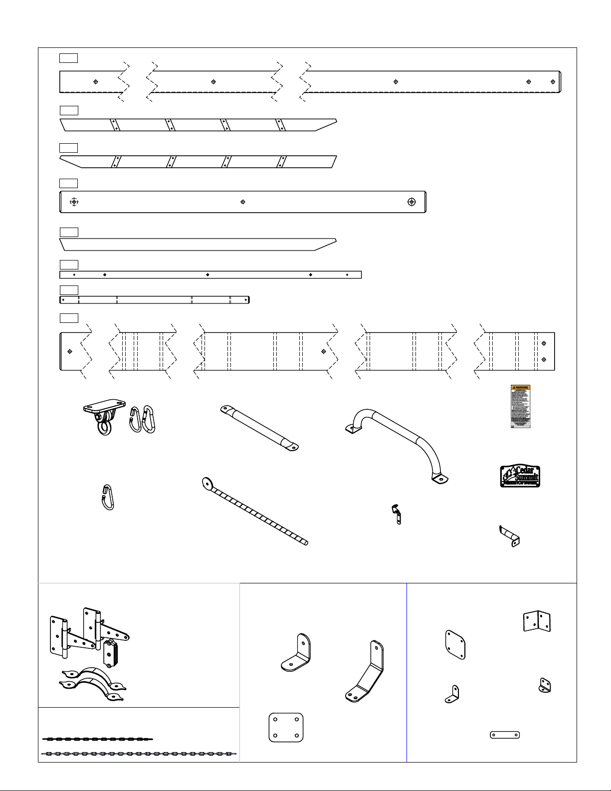
Part Identification (53" Add On A)
(2)
152 - 4 x 4 x 92" - SW Post -
(1)
020 - 1-3/8 x 2-1/2 x 57-53/64" - Left Access -
(1)
021 - 1-3/8 x 2-1/2 x 57-53/64" - Right Access -
(1)
160 - 2-1/2 x 3 x 51" - Support Cross -
(1)
024 - 1-3/8 x 2-1/2 x 57-53/64" - Rock Rail -
(2)
061 - 2 x 2 x 63" - Side Joist -
(1)
130 - 2 x 2 x 39-5/8" - Table Support -
(1)
140 - 4 x 6 x 92" - Engineered SW Beam -
3599070
3599054
3599055
3599067
3599058
3599064
3592612
3599049
(Reduced Size)
1x
- DX Swing Hangers
with Quick Links (6 Pk)
(3201950)
1x
- Quick Links w.
Thread (2pk)
(3200022)
1x
- Door Hardware (3201710)
1x
- Welded Chain Bag (3200173) Green
2x
20" chain -Green
4x
48" chain -Green
1x
- Acro Bar
(9200131) Green
1x
- Rebar Ground
Stake (6 Pk)
(3200318)
2x
9201712
Door Hinge -Green
9207713
Door Catch -Brown
1x
Magnetic Catch
1x
Catch Plate
2x
9201711
Door Handle -Green
1x
- Heavy Bracket Set
(3205701) Green
3x
- Heavy L-Bracket
(9200151)
2x
- Heavy Flat Bracket
(9200149)
2x
- Steel Hand Grip
(9200211) -Yellow
1x
- TNR 3 Post Mount
(9200257) -Yellow
1x
- Heavy C-Bracket
(9200153)
1x
1x
- Bracket Set (3205700)
1x
- Flat Panel Bracket
(5 Pk)(3205935)
2x
- Narrow Angle
Bracket (2 Pk)
(3205939)
1x
1x
- Cedar Summit
ID Plaque (9320357)
1x
- Cedar Summit
Plaque (9320358)
- TNR 3 Tube Support
(9200258) -Yellow
2X
- Corner
Panel
Bracket (4 Pk)
(3205975)
1x
- Corner
Bracket (3 Pk)
(3205970)
- Small Jamb Mount
(2 Pk) (3205947)
Page 10
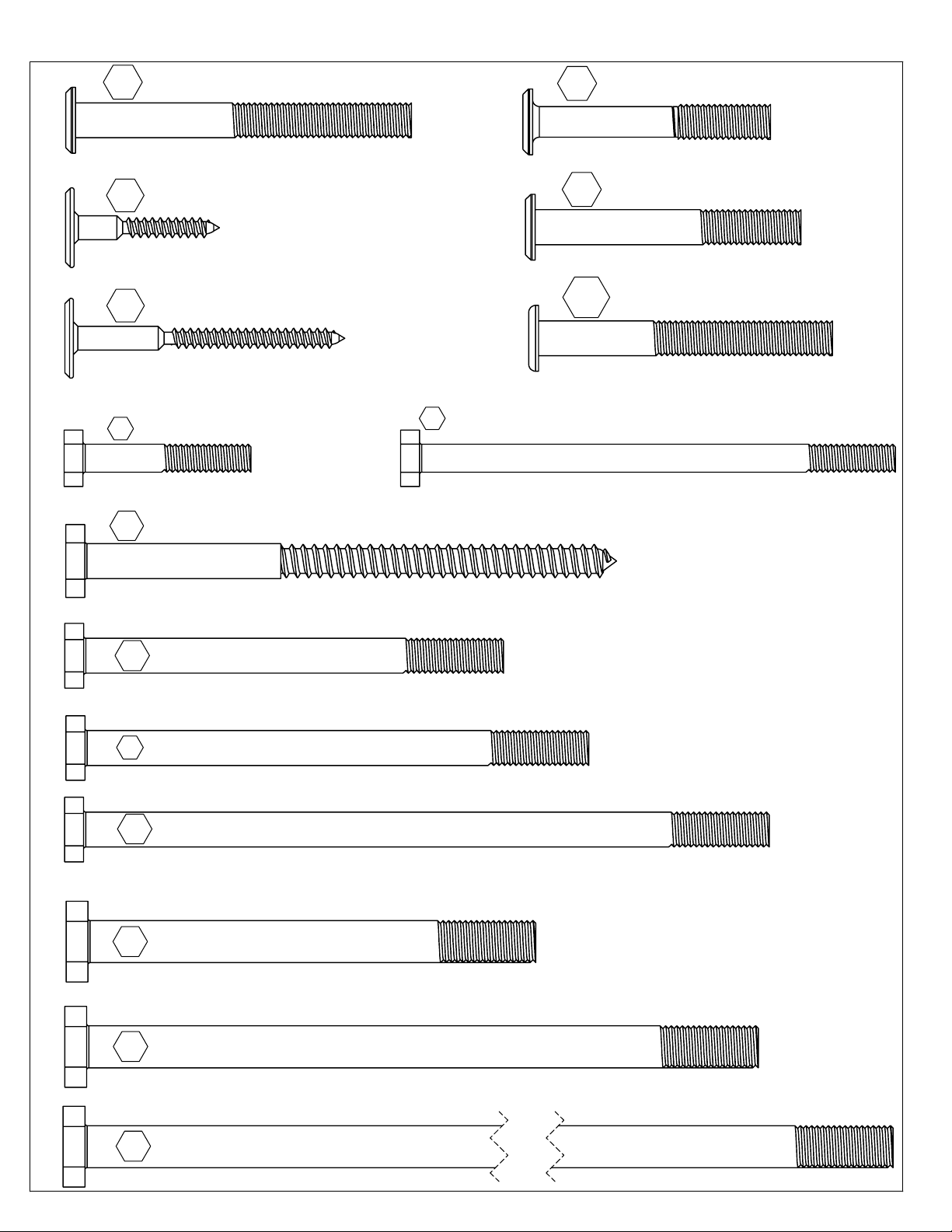
Hardware Identification
(53" Add On A)
(Actual Size)
(7)
WB7 -
(4)
WL3 - Wafer Lag
(17)
WL5 - Wafer Lag
(4) H1
(5)
-
LS9 - Lag Screw
Wafer Bolt 5/16 x 3"
1/4 x 1-3/8"
1/4 x 2-1/2"
Hex Bolt 1/4 x 1-1/2"
5/16 x 4-3/4"
- (53613330)
- (52613216)
- (52613222)
- (53703212)
- (52213343)
(1) H8
(5)
WB9 -
(7)
WB8 -
(7)
WB10 -
Hex Bolt 1/4 x 4-1/4"
-
Wafer Bolt 5/16 x 2-1/8"
Wafer Bolt 5/16 x 2-3/8"
Wafer Bolt 5/16 x 2-5/8"
- (53703241)
- (53613324)
- (53613326)
- (53613330)
(4)
G21 -
(2) G5 -
(12)
G13 -
(1)
G20 -
(4)
G17 -
Hex Bolt 5/16 x 3-3/4"
Hex Bolt 5/16 x 4-1/2"
Hex Bolt 5/16 x 6-1/8"
Hex Bolt 3/8 x 4"
Hex Bolt 3/8 x 6"
- (53703840)
- (53703860)
- (53703333)
- (53703342)
- (53703364)
(1)
Hex Bolt 3/8 x 9-1/4"
G26 -
- (53703891)
Page 11
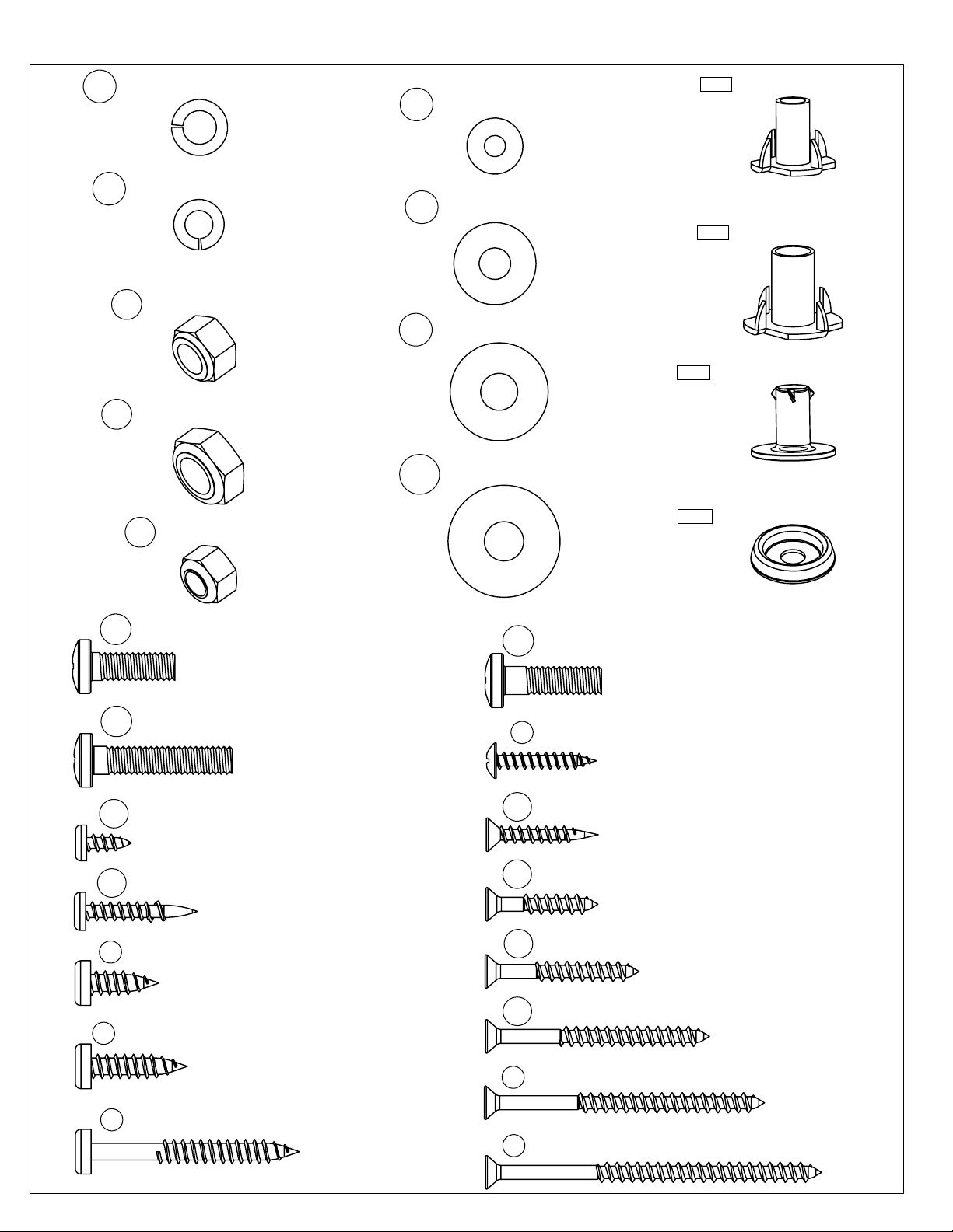
Hardware Identification
(1)
LW2 - 5/16" Lock Washer - (51303300)
(14)
LW1 - 1/4" Lock Washer - (51303200)
(53" Add On A)
(9)
FW0 - 3/16" Flat Washer - (51103100)
(11)
FW1 - 1/4" Flat Washer - (51103200)
(Actual Size)
(5)
TN1 - 1/4" T - Nut -(54503200)
(26)
TN2 - 5/16" T- Nut
-
(54503300)
(18)
LN2 - 5/16" Lock Nut
(6)
(89)
(10)
3/8 Lock Nut
LN3 -
(89)
LN1 -
PB1 - Pan Bolt
PB2 - Pan Bolt
- (54303800)
1/4 Lock Nut
1/4 x 3/4"
1/4 x 1-1/4"
-
(54303300)
- (54303200)
- (53453203)
- (53433212)
(70)
FW2 - 5/16" Flat Washer - (51103300)
(12)
FW10 - 3/8" Flat Washer - (51103800)
(1)
PB6 - Pan Bolt
(10) S0
- Truss Screw
1/4 x 1"
#8 x 7/8"
(9) BN1
(8)
- (53413210)
- 1/4" Barrel Nut
FW6
- #8 Screw Bezel
- (52933505)
-
(54803200)
-
(9299500)
(12)
(33)
S13 - Pan Screw
(21)
S10 - Pan Screw
(52) S8
(17) S6
(28) S7
- Pan Screw
- Pan Screw
- Pan Screw
#6 x 5/8"
#8 x 1"
#12 x 3/4"
#12 x 1"
#12 x 2"
- (52413908)
- (52433510)
- (52433603)
- (52433610)
- (52433620)
S18 - Wood Screw
(28)
S33 - Wood Screw
(215)
S20 - Wood Screw
(76)
S11 - Wood Screw
(47) S3
(21) S4
- Wood Screw
- Wood Screw
#6 x 1"
#8 x 1"
#8 x 1-3/8"
#8 x 2"
#8 x 2-1/2"
#8 x 3"
- (52013910)
- (52043510)
- (52043516)
- (52043520)
- (52043522)
- (52043530)
Page 12
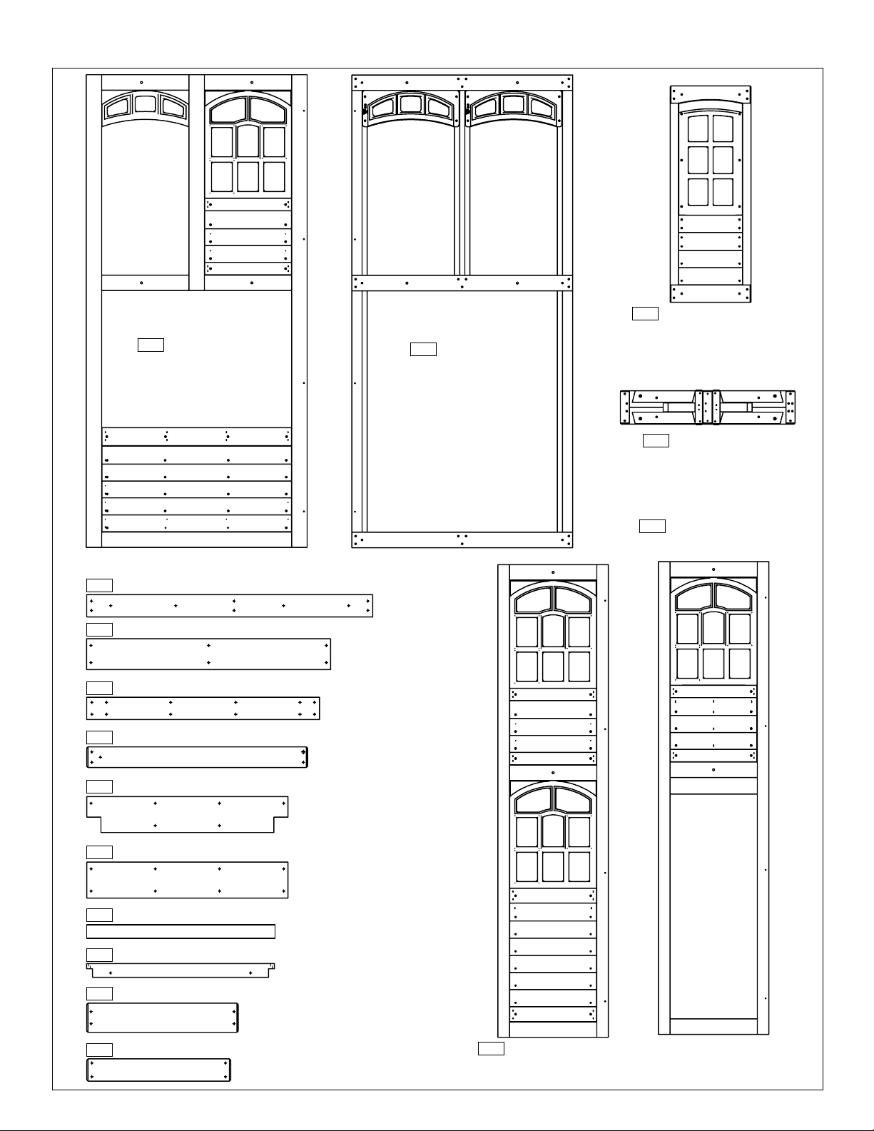
Part Identification (53" Add On B)
(1)
051 - 1-1/4 x 43 x 92"
Front Wall Panel
37598971
(1)
052 - 1-1/4 x 43 x 92"
Back Wall Panel
37598970
(Reduced Size)
(1)
120 - 1-1/4 x 15-3/4 x 42-1/8"
(1)
Folding Bench
Door Window Panel
37608977
010 - 2-13/32 x 6-3/4 x 34"
37592658
(1)
025 - 1 x 4 x 41-3/4" - RW - AL Support -
(10)
070 - 1 x 5 x 35-5/8" - Floor Board -
(1)
192 - 5/4 x 4 x 34" - Crowsnest Back -
(1)
280 - 1-1/4 x 3 x 32-1/4" - TNR Ground Brace -
(1)
220 - 1 x 6 x 29-3/8" - Crowsnest Gap Board -
(2)
221 - 1 x 6 x 29-3/8" - Crowsnest Floor -
(2)
204 - 1-1/4 x 2 x 27-1/2" - Crowsnest Spacer -
3599062
3599051
3599036
3598963
3599040
3599038
3599043
(1)
042 - 1-1/4 x 21-1/2 x 92"
Narrow Front Panel
37599003
(1)
133 - 1 x 2 x 27-7/16" - Chalkwall Side -
(1)
031 - 1 x 5 x 22-1/8" - Access Board -
(1)
023 - 1 x 4 x 21" - Ladder Gap -
3598958
3599035
3599032
(1)
041 - 1-1/4 x 21-1/2 x 92"
Narrow Back Panel
37598992
Page 13
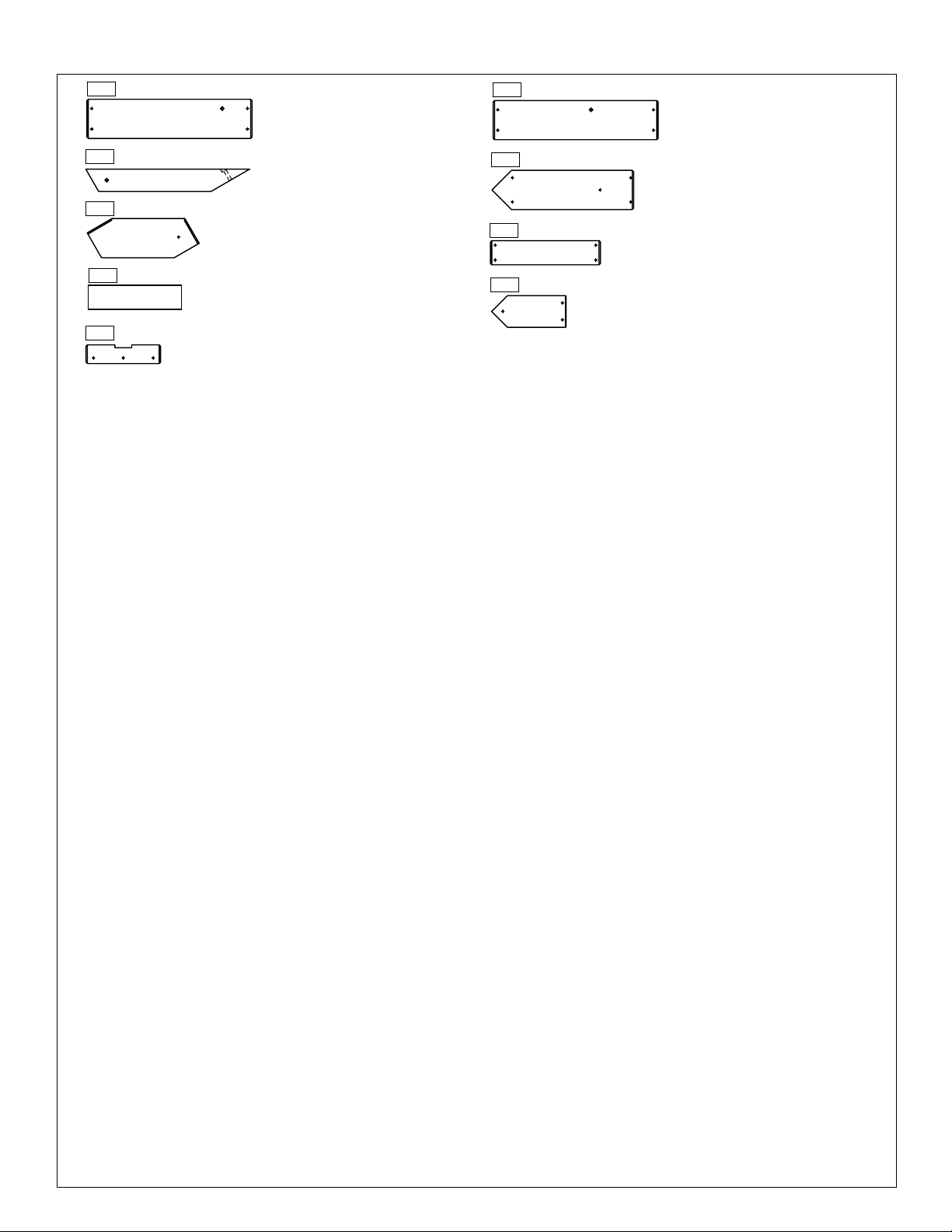
Part Identification (53" Add On B)
(4)
032
- 1 x 6 x 22-1/8" -
(1)
091 - 1-1/4 x 3 x 22" - Diagonal -
(2)
190 - 2 x 6 x 15" Crowsnest Gusset -
(2)
211 - 2 x 4 x 12-1/2" - Short Crowsnest Joist
(1)
121 - 5/4 x 3 x 10" - Door Stop -
Board Rock A -
-
3599063
3598511
3592607
3598112
3592715
(5)
033 - 1 x 6 x 22-1/8" - Board Rock B -
(1)
361 - 1 x 6 x 19" - Bk Centre Gable -
(2)
212 - 3/4 x 3-1/4 x 14-3/4" - Crowsnest Side -
(4)
363 - 1 x 5 x 10" - Sunburst Side -
(Reduced Size)
3598512
3599033
3599042
3599066
Page 14
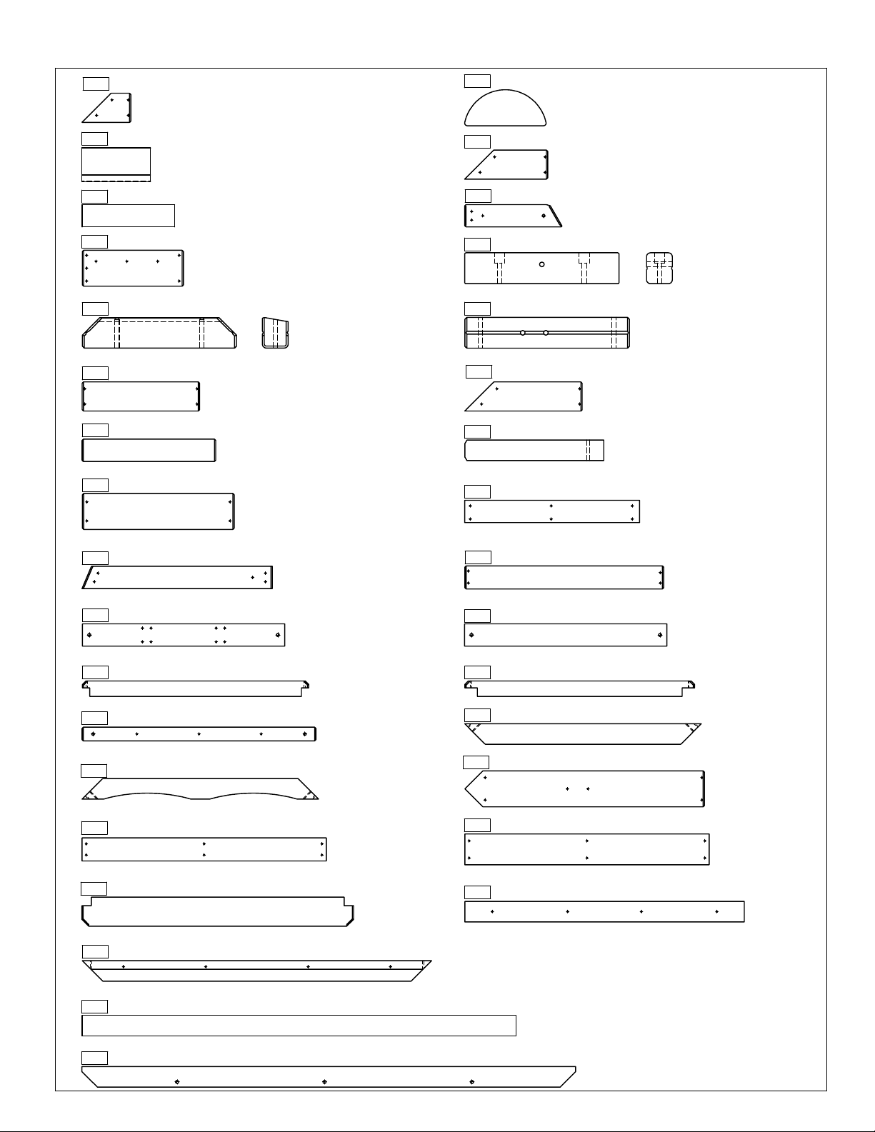
Part Identification (53" Add On C)
(2)
394 - 1 x 5 x 7-1/8" - End Gable C
-
3599047
(1)
132 - 1-1/4 x 5 x 10" - Chalkwall Block
-
(2)
191 - 2 x 4 x 13-1/2" - Crowsnest Joist
-
(2)
210 - 3/4 x 5-1/4 x 14-3/4" - Crowsnest Bottom Side
(1)
150 - 2-1/2 x 3 x 15" - SW Block Angle -
(2)
391 - 1 x 5 x 17-1/8" - End Gable A -
(4)
022 - 5/4 x 4 x 19-1/2" - Tread -
3599034
3599041
-
3599037
3599068
3599045
3598957
(2)
(2)
(1)
(1)
(1)
(2)
(1)
(Reduced Size)
362 - 5/4 x 6 x 12" - Starburst Centre
-
3598305
393 - 1 x 5 x 12-1/8" - End Gable B
-
090 - 5/4 x 4 x 14¼ - SW Ground
-
151 - 2-1/2 x 3 x 15" - Block SW -
141 - 4 x 4 x 16" - SW Mount -
392 - 1 x 5 x 17-1/8" - End Gable D
-
281 - 1-1/4 x 3 x 20-1/4" - TNR Upright -
3599046
3592606
3598507
3599069
3599048
3598965
(1)
030 - 1 x 6 x 22-1/8" - Access Rock Bottom
-
(1)
100 - 5/4 x 4 x 27-3/4" - RW-AL Ground Brace
-
(1)
202 - 2 x 4 x 29-1/2" - Crowsnest Front -
(1)
081 - 5/4 x 3 x 33" - Half Wall Top -
(2)
201 - 1 x 2 x 34-1/8" - Upright Crowsnest -
(1)
370 - 1-1/4 x 3 x 34-1/2" - Mid Gable Support
-
(1)
072 - 1 x 4 x 35-5/8" - Floor Board -
(1)
131 - 5/4 x 5 x 39-5/8" - Table Top -
3598515
3599061
3599053
3599050
3592611
3599039
3599072
3599057
(1)
203 - 5/4 x 4 x 25-1/2" - Crowsnest Short
-
(4)
230 - 1 x 4 x 29" - Cedar Wall -
(1)
200 - 2 x 4 x 29-1/2" - Crowsnest Top -
(1)
080 - 5/4 x 3 x 33-1/2" - SW Wall Top -
(1)
360 - 1-1/4 x 3 x 34-1/2" - Back Gable Support
-
(1) -390 - 1 x 6 x 34-15/16" - Fr Centre Gable -
(3)
070 - 1 x 5 x 35-5/8" - Floor Board -
(2)
060 - 1-1/4 x 3 x 40-3/4" - Floor Joist -
3598115
3591975
3599071
3599051
3592608
3599044
3599031
3599052
(4)
340 - 1-1/4 x 3 x 50-15/16" - Roof Rafter -
(1)
071 - 1-1/4 x 3 x 63-1/4" - Long Floor Joist -
(2)
062 - 1-1/4 x 3 x 72" - Roof Support -
3599059
3599056
3599060
Page 15
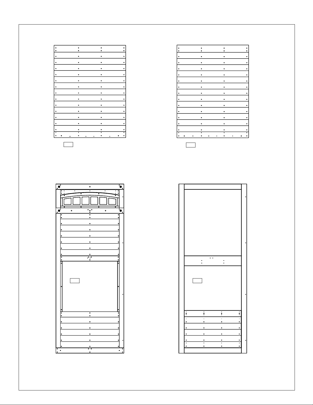
Part Identification (53" Add On C)
(1)
350 - 1-1/4 x 39 x 50-3/16"
Roof Panel A -
37599022
(Reduced Size)
(1)
351 - 1-1/4 x 39 x 50-7/16"
Roof Panel B -
37599029
(1)
(1)
050 - 1-1/4 x 37 x 92"
SW Wall Panel
37599007
040 - 1-1/4 x 37 x 92"
Slide End Panel
37598981
Page 16
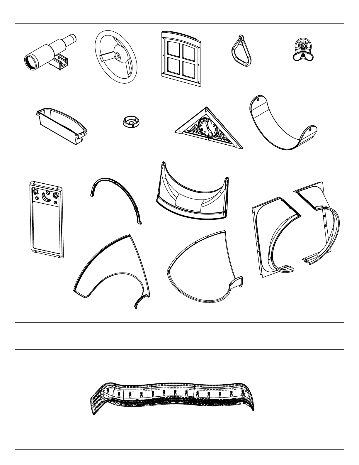
Part Identification
1x
- Telescope w/ Mount
(3320161)
2x
- Flower Box
(9320401) Green
1x
- Steering Wheel
(53" Add On D)
2x
- 2 x 2 Panel Window
(9320118) -Green
(3320255)
1x
- Plastic Formed
Washer (18 Pk)
(3290000)
(Reduced Part Size)
2x
- Acro Handle
(9320131) Green
1x
- Gable Clock Assembly
(3320164) Green
1x
- TNR3 Short Exit
(3310232) Yellow
1x
- Rocks (9pk)
(3320093)
Green/Yellow/Burgundy
2x
- Swing Belt Seat
(9320130) Green
- TNR 2 Slide Rt Flange
1x
(3310223) Yellow
1x
- TNR 2 Slide
Clamp Ring (10Pk)
(3300220) Yellow
1x
- Sky Chalk
Wall (3320117)
1x
- TNR 2 Slide Exit Top
(3310224) Yellow
Part Identification
9x
(53" Add On E)
- TNR 2 Slide Elbow
(3310221) Yellow
1x
(3310222) Yellow
(Reduced Part Size)
- TNR 2 Slide Lt Flange
1x
- Maze N Wave 2.35m Slide
(3318215) Yellow
Page 17
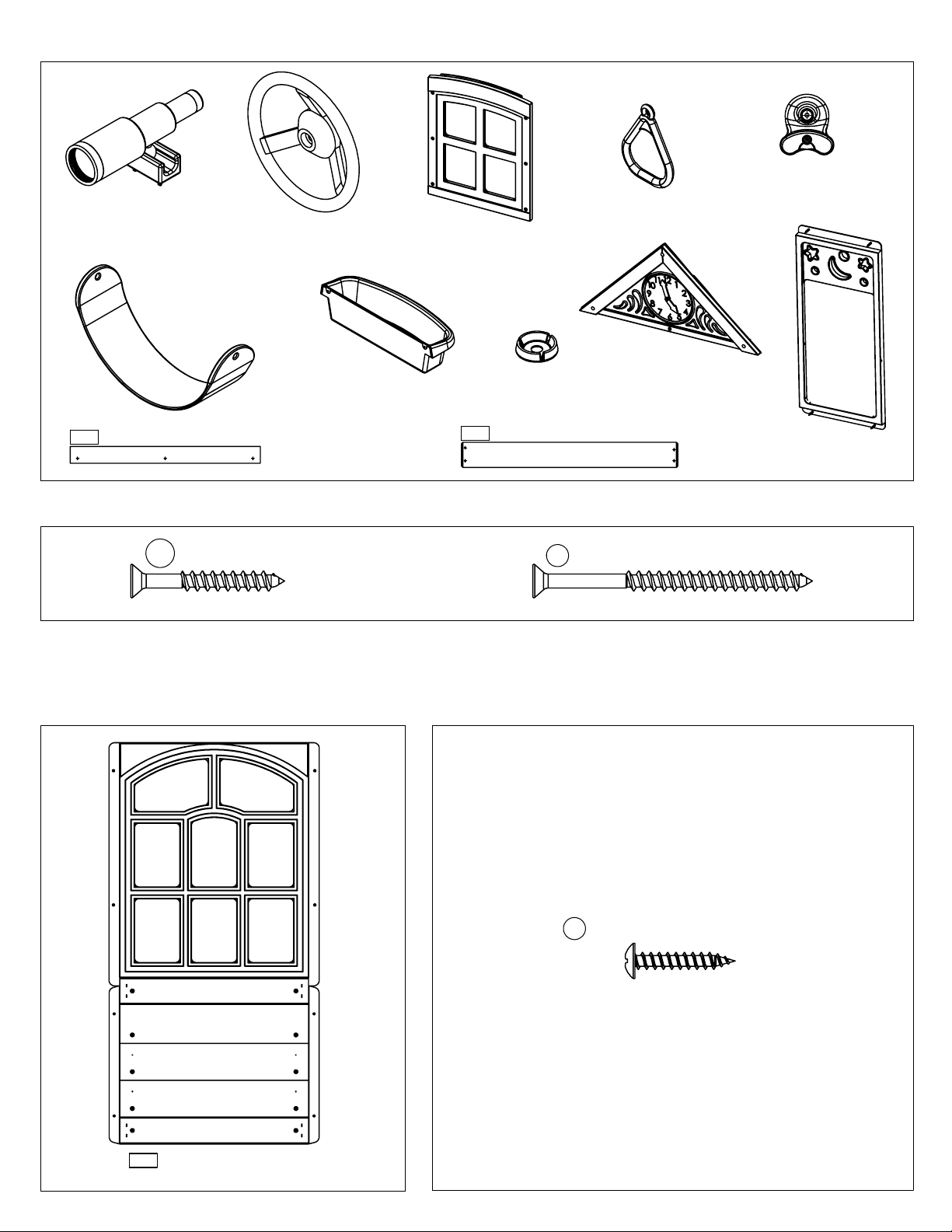
Part Identification
1x
- Telescope w/ Mount
(3320161)
2x
- Swing Belt Seat
(9320130) Green
(1)
460 - 1-1/4 x 2-1/4 x 25-1/2" - Wall Board Support
-
(53" Add On F)
1x
- Steering Wheel
(3320255)
2x
- Flower Box
(9320401) Green
3592915
(Reduced Part Size)
2x
- 2 x 2 Panel Window
(9320118) -Green
1x
- Plastic Formed
Washer (18 Pk)
(3290000)
(4)
230 - 1 x 4 x 29" - Cedar Wall -
2x
- Acro Handle
(9320131) Green
1x
- Gable Clock Assembly
(3320164) Green
3591975
1x
- Rocks (9pk)
(3320093)
Green/Yellow/Burgundy
1x
- Sky Chalk
Wall (3320117)
Hardware Identification (53" Add On F)
(16)
S20 - Wood Screw
#8 x 1-3/8"
Part Identification
(53" Add On G)
(Reduced Part Size)
- (52043516)
(3) S3
Hardware Identification
(53" Add On G)
(Actual Size)
(9) S0
(Actual Size)
- Wood Screw
- Truss Screw
#8 x 2-1/2"
#8 x 7/8"
- (52043522)
- (52933505)
(1)
470 - Upper Window Insert
1.27 x 18.8 x 35.86 -
37592655
Page 18
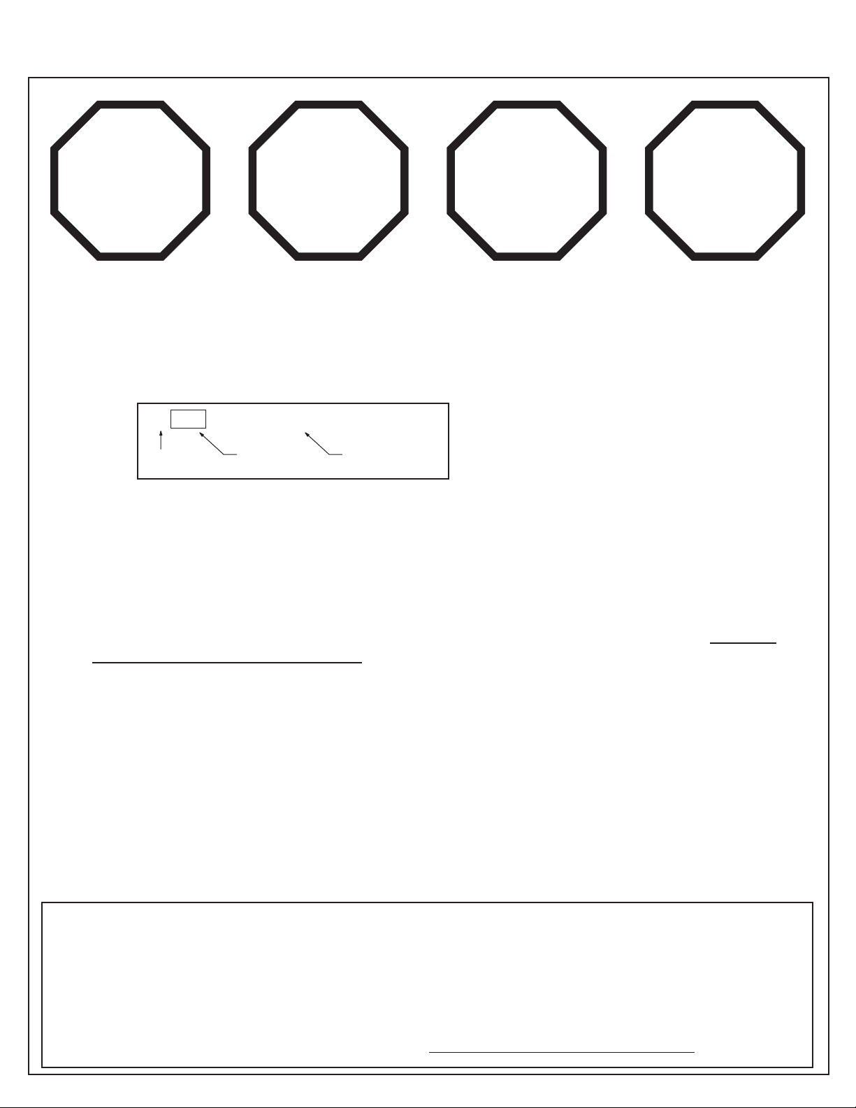
First Step: Inventory Parts - Read This Before Starting Assembly
STOP STOPSTOP STOP
A. This is the time for you to inventory all your hardware, wood and accessories,
referencing the parts identication sheets. This will assist you with your assembly.
• The wood pieces will have the key number stamped on the ends of the boards.
Organize the wood pieces by step, as per the key numbering system below.
2X 012 Post 2 x 4 x 83”
Quantity Key Number Part Description,
Part Size
Key Number: The rst two digits represent the step
number. The third digit represents the piece. Note
that if the part is used in multiple steps then the
number only reects the rst step it is used in.
• Please refer to Page 6 for proper hardware assembly.
• Each step indicates which bolts and/or screws you will need for assembly, as well as
any at washers, lock washers, t-nuts or lock nuts.
B. If there are any missing or damaged pieces or you need assistance with
assembly please contact the consumer relations department directly. Call us
before going back to the store.
1-877-817-5682
C. Read the assembly manual completely, paying special attention to ANSI warnings;
notes; and safety/maintenance information on pages 1 - 6.
D. Before you discard your cartons ll out the form below.
• The carton I.D. stamp is located on the end of each carton. The tracking number is
located on the Cedar Summit ID Plaque (9320357).
• Please retain this information for future reference. You will need this information if you
contact the Consumer Relations Department.
MODEL NUMBER: Brockwell / Preston / Twin Mountain Lodge
CARTON I.D. STAMP: __ __ __ __ __ 14459 ___ (Box 1)
CARTON I.D. STAMP: __ __ __ __ __ 14459 ___ (Box 2)
CARTON I.D. STAMP: __ __ __ __ __ 14459 ___ (Box 3)
TRACKING NUMBER (from ID Plaque):
CARTON I.D. STAMP: __ __ __ __ __ 14459 ___ (Box 4)
CARTON I.D. STAMP: __ __ __ __ __ 14459 ___ (Box 5)
CARTON I.D. STAMP: __ __ __ __ __ 14459 ___ (Box 6)
Page 19
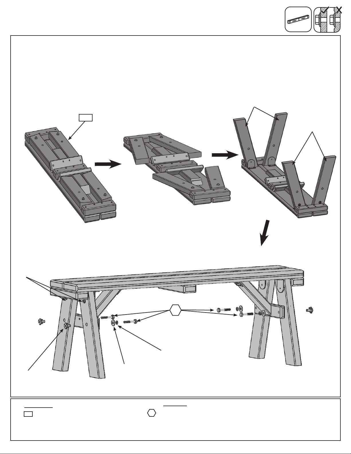
Step 1: Bench Assembly
A: Open the Folding Bench Assembly. (g. 1.1, 1.2 and 1.3)
B: Make sure assembly is level then secure with 2 (H1) 1/4 x 1-1/2” Hex Bolts (with lock washer, at washer and
t-nut) per side. (g. 1.4)
C: Tighten the top screws in all 4 Bench Legs. (g. 1.4)
Bench Legs
Fig. 1.3
Bench Legs
Fig. 1.1
010
Fig. 1.2
Tighten these
screws - all 4 legs
1/4” t-nut
Wood Parts
010
1 x Folding Bench 2-13/32 x 6-3/4 x 34”
Fig. 1.4
1/4” at
washer
H1
1/4” lock
washer
Hardware
H1
4 x 1/4 x 1-1/2” Hex Bolt
(1/4”lockwasher,1/4”atwasher,1/4”t-nut)
Page 20
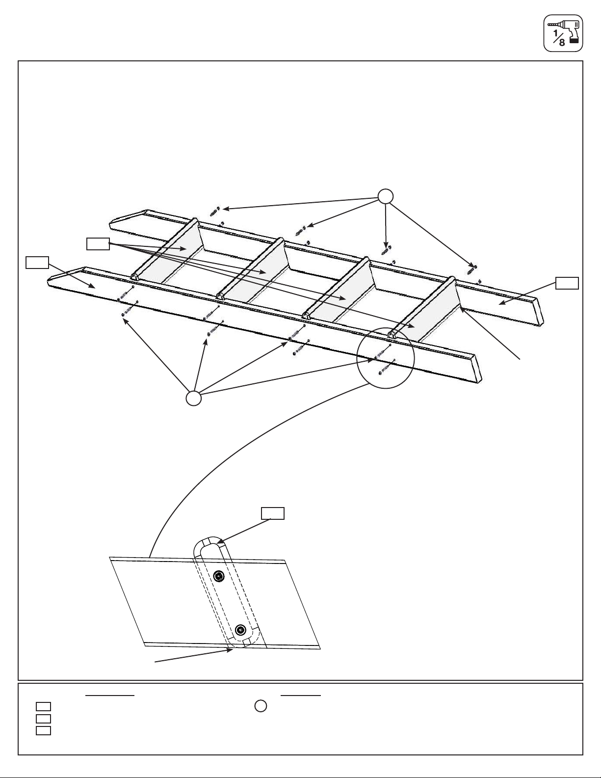
Step 2: Access Ladder / Rockwall Assembly
Part 1
A: Place (020) Left Access on one side of 4 (022) Treads and (021) Right Access on the other side with the
grooves facing in. (g. 2.1)
B: Fit each (022) Tread into grooves on both (020) and (021) Access rails, make sure the top edge of the (022)
Treads are ush to the front of the Access rails. (g. 2.1 and 2.2)
C: Pre-drill pilot holes with a 1/8” drill bit and attach rails and treads together using 4 (S3) #8 x 2-1/2” Wood
Screws per tread. (g. 2.1)
S3
Fig. 2.1
022
021
020
Fig. 2.2
End View
Flush to
top edge
S3
022
Flush to
edges
Wood Parts Hardware
1 x Left Access 1-3/8 x 2-1/2 x 57-7/8”
020
021
1 x Right Access 1-3/8 x 2-1/2 x 57-7/8”
022
4 x Tread 5/4 x 4 x 19-1/2”
Top Edge of Access Rail
S3
16 x #8 x 2-1/2” Wood Screw
Page 21
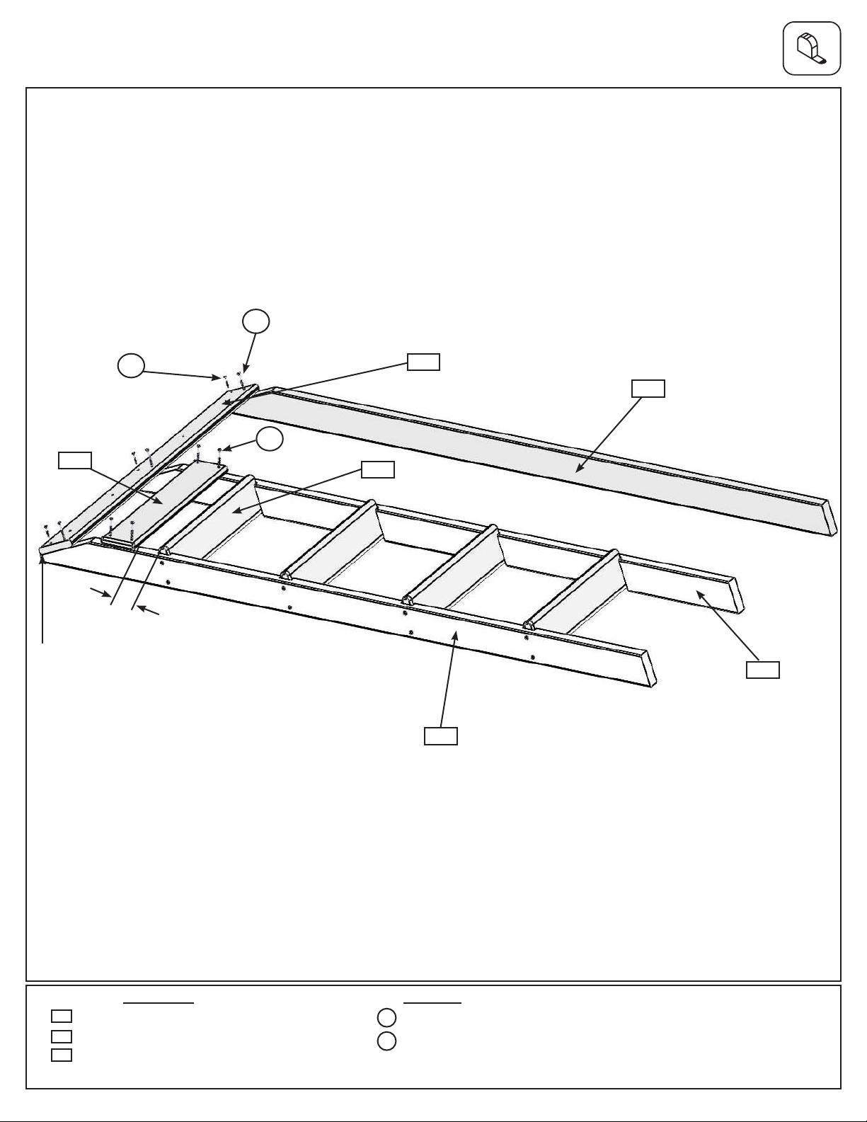
Step 2: Access Ladder / Rockwall Assembly
Part 2
D: Place (023) Ladder Gap on each access rail so there is a 2-3/8” gap between (023) Ladder Gap and the top
(022) Tread. Attach using 4 (S11) #8 x 2” Wood Screws. (g. 2.3)
E: Place (024) Rock Rail on the ground next to (020) Left Access so it matches the orientation of the two access
rails as shown in g. 2.3. Attach (025) RW-AL Support ush to the top of Access Ladder assembly and (024)
Rock Rail using 3 (S20) #8 x 1-3/8” Wood Screws in the top holes and 3 (S11) #8 x 2” Wood Screws in the
bottom holes. Pilot holes in (025) RW-AL Support should be centred over the rails. (g. 2.3)
Fig. 2.3
S11
x 3 in bottom holes
x 3 in top holes
023
2-3/8” gap between top
Tread and Ladder Gap
Flush
S20
S11
025
024
x 4
022
020
021
Wood Parts Hardware
023
1 x Ladder Gap 1 x 4 x 21”
024
1 x Rock Rail 1-3/8 x 2-1/2 x 57-7/8”
025
1 x RW-AL Support 1 x 4 x 41-3/4”
S11
7 x #8 x 2” Wood Screw
S20
3 x #8 x 1-3/8” Wood Screw
Page 22
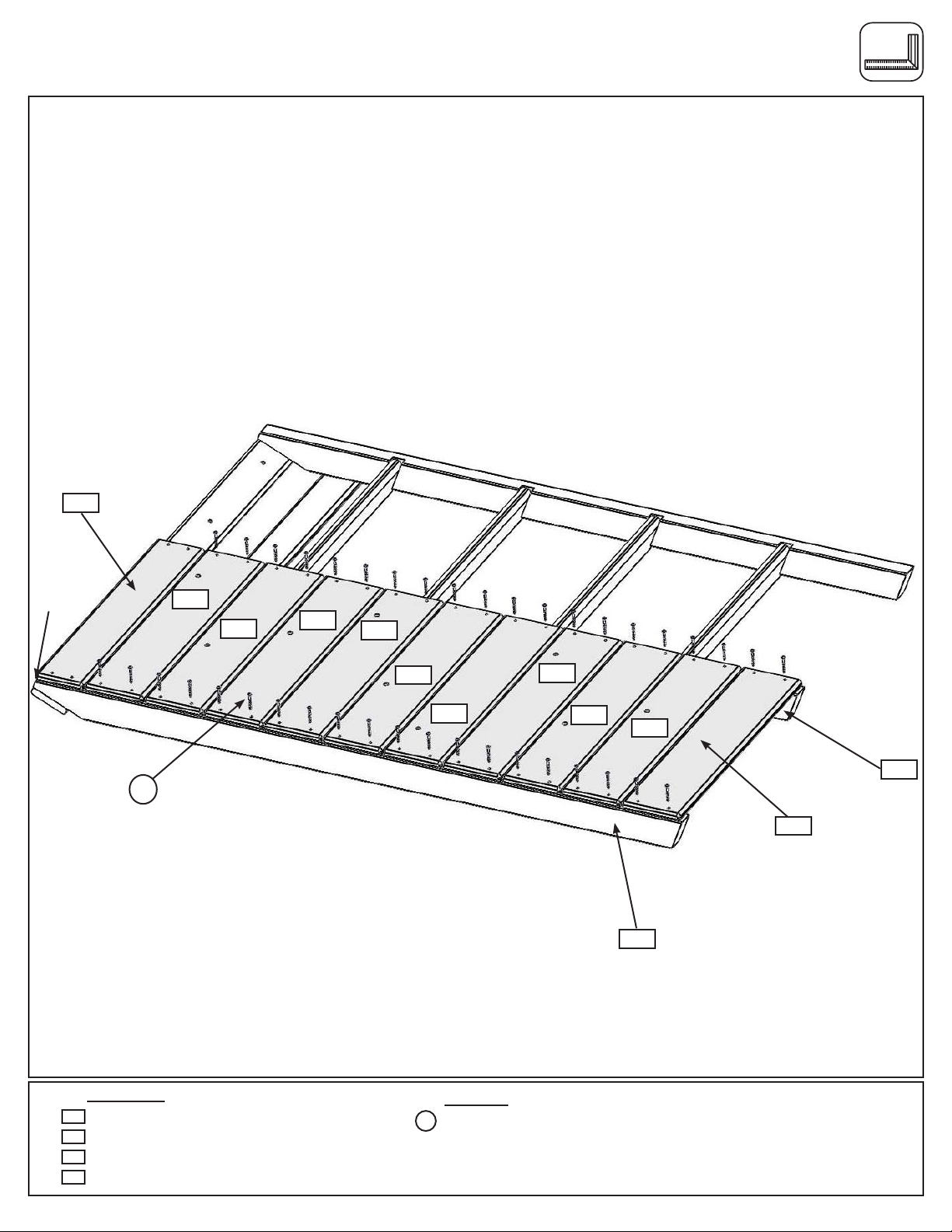
Step 3: Rockwall Assembly
Part 1
A: Place (031) Access Board ush to the top of the Access Ladder/Rockwall Assembly and (030) Access Rock
Bottom at the bottom of the assembly as shown in g. 3.1. Then place (032) Board Rock A and (033) Board Rock
B as shown in g. 3.1. Do not screw boards down yet. Rock holes are to be staggered so they do not form a
straight line and are at the top of the boards. Note: Rock Boards are to be ush to (020) Left Access and pilot
holes are centred over (024) Rock Rail. (g. 3.1)
B: Make sure all boards are tight together and the assembly is square, then attach all boards except for (031)
Access Board using 4 (S20) #8 x 1-3/8” Wood Screws per board. (031) Access Board to be attached in Step 10,
Part 2, keep aside until needed. (g. 3.1)
Fig. 3.1
Do not attach yet,
031
put aside until
Step 10
Flush
S20
x 4 per
board
032
033
033
032
IMPORTANT!
Follow hole
pattern
033
032
032
033
033
020
030
024
Wood Parts
030
1 x Access Rock Bottom 1 x 6 x 22-1/8”
031
1 x Access Board 1 x 5 x 22-1/8”
032
4 x Board Rock A 1 x 6 x 22-1/8”
033
5 x Board Rock B 1 x 6 x 22-1/8”
40 x #8 x 1-3/8” Wood Screw
Hardware
S20
Page 23
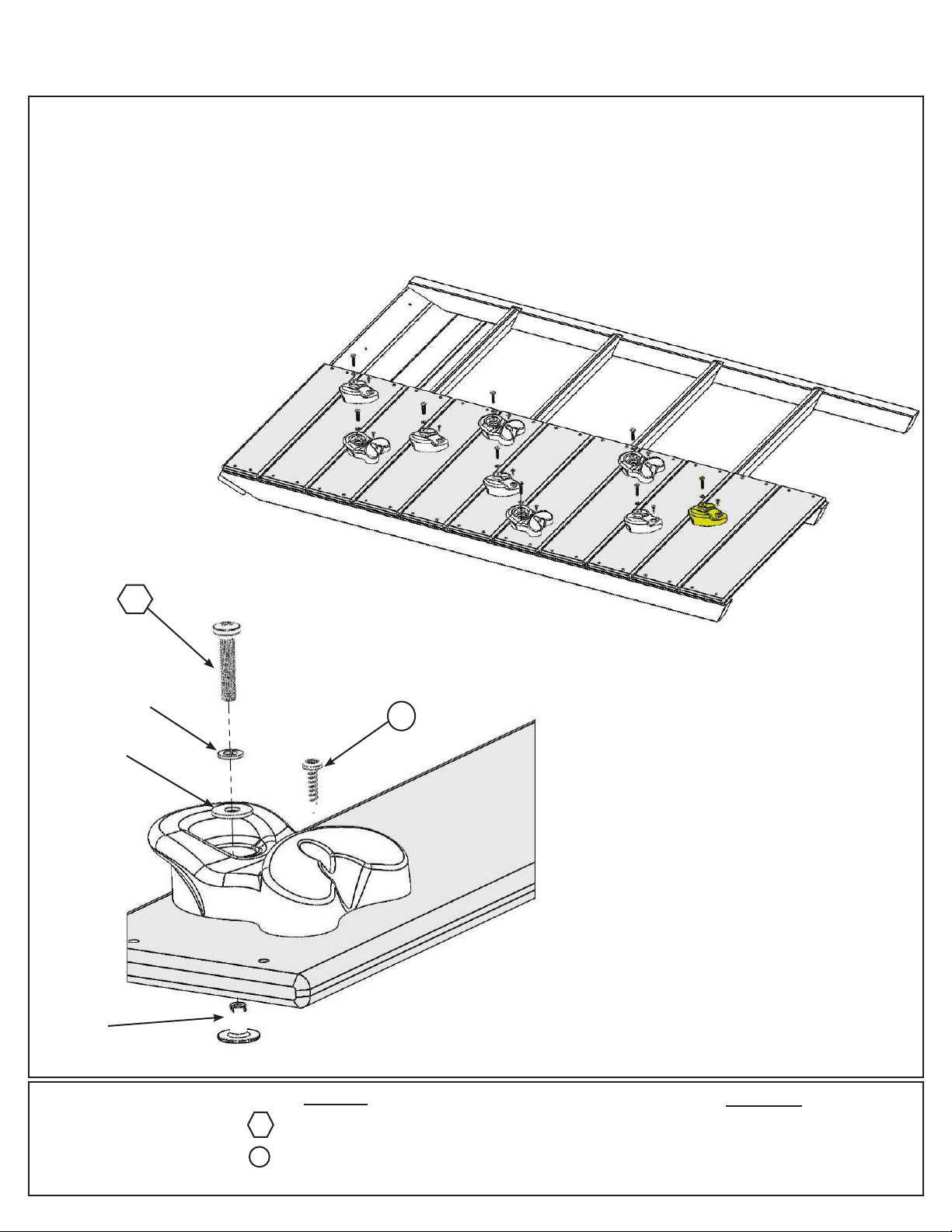
Step 3: Rockwall Assembly
Part 2
C: Alternating colours and shapes, attach 1 rock to each rock board using 1 (PB2) 1/4 x 1-1/4” Pan Bolt (with
lock washer, at washer and barrel nut) and 1 (S10) #8 x 1” Pan Screw per rock. (g. 3.2 and 3.3)
The Pan Screw is placed in the hole beneath the Pan Bolt. (g. 3.2 and 3.3)
Note: Make sure all hardware is used to secure each rock properly.
Fig. 3.2
1/4” Lock
Washer
3/16” Flat
Washer
1/4”
Barrel Nut
PB2
Fig. 3.3
S10
Hardware
PB2
9 x 1/4 x 1-1/4 Pan Bolt
(1/4”lockwasher,3/16”atwasher&1/4”barrelnut)
S10
9 x #8 x 1” Pan Screw
Other Parts
9xRocks(green/yellow/burgundy)
Page 24
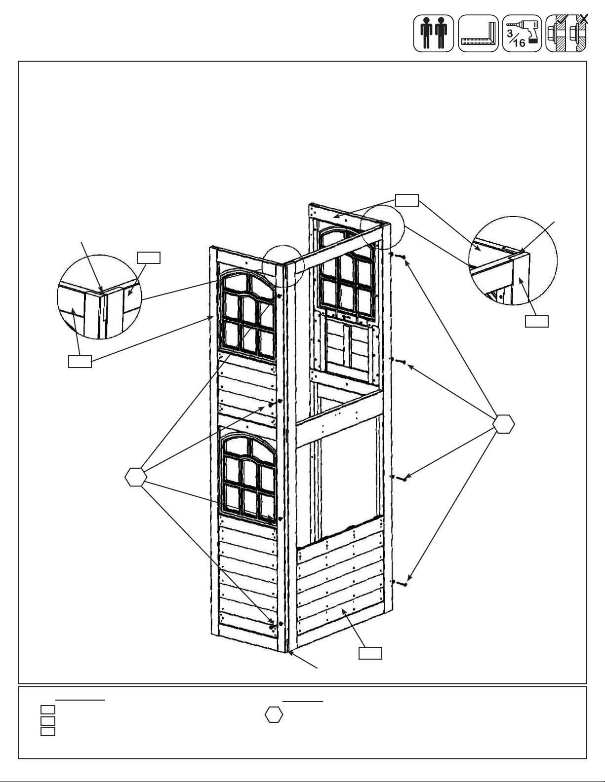
Step 4: Slide Wall Assembly
A: Place (041) Narrow Back Panel against the left side of (040) Slide End Panel noticing panel orientation. The
tops and bottoms of the panels should be ush and panels square. Pre-drill with a 3/16” drill bit, then fasten
(041) Narrow Back Panel to (040) Slide End Panel with 4 (WL5) 1/4 x 2-1/2” Wafer Lags. (g. 4.1 and 4.2)
B: Place (042) Narrow Front Panel against the right side of (040) Slide End Panel noticing panel orientation.
The tops and bottoms of the panels should be ush and panels square. Pre-drill with a 3/16” drill bit, then fasten
(040) Slide End Panel to (042) Narrow Front Panel with 4 (WL5) 1/4 x 2-1/2” Wafer Lags. (g. 4.1 and 4.3)
Fig. 4.2
Flush
041
Notice(041)Narrow
Back Panel overlaps
(040)SlideEndPanel
WL5
040
Fig. 4.1
042
Fig. 4.3
Flush
040
Notice(040)SlideEnd
Paneloverlaps(042)
Narrow Front Panel
WL5
040
Flush
Wood Parts
040
1 x Slide End Panel 1-1/4 x 37 x 92”
041
1 x Narrow Back Panel 1-1/4 x 21-1/2 x 92”
042
1 x Narrow Front Panel 1-1/4 x 21-1/2 x 92”
8 x 1/4 x 2-1/2” Wafer Lag
Hardware
WL5
Page 25
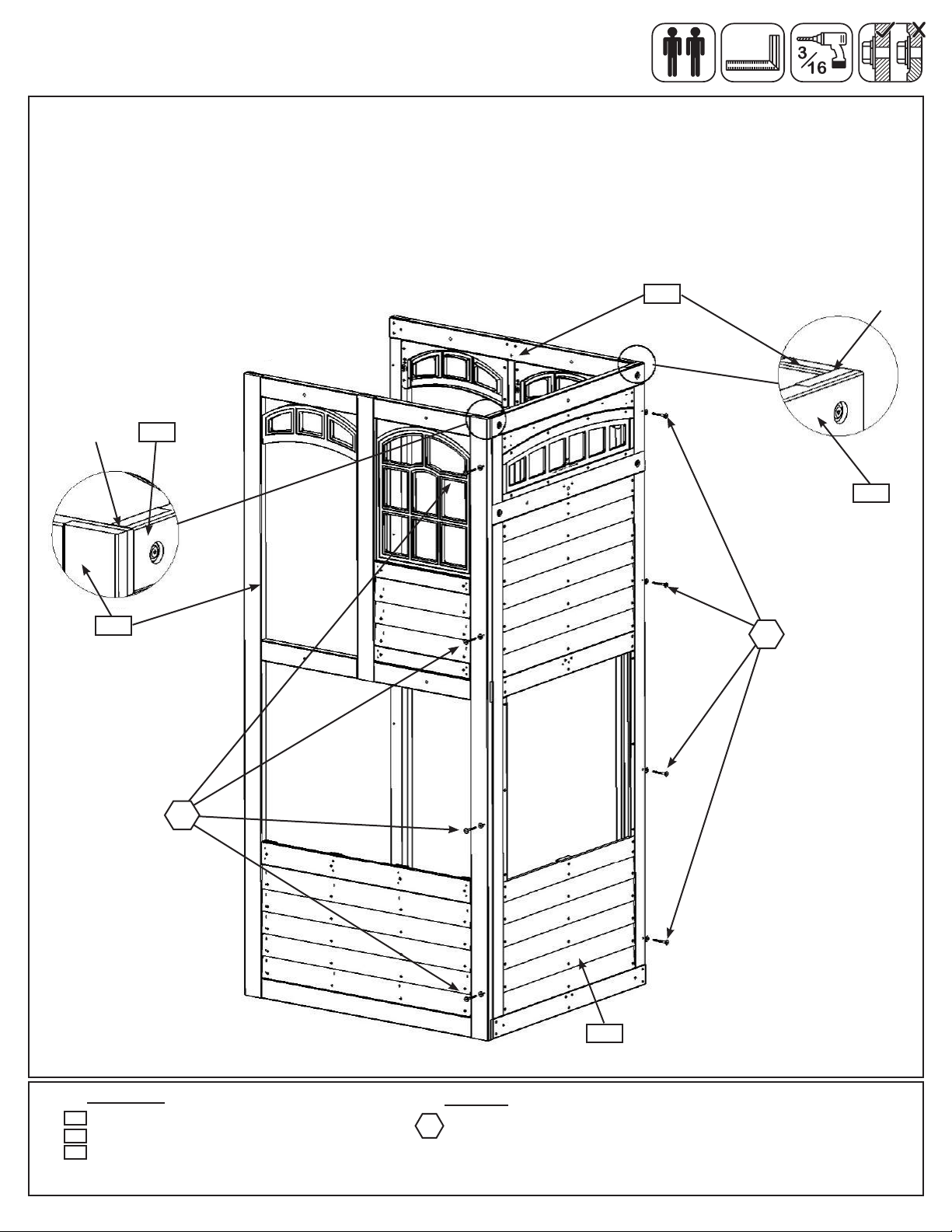
Step 5: Swing Wall Assembly
A: Place (051) Front Wall Panel against the left side of (050) SW Wall Panel noticing panel orientation. The tops
and bottoms of the panels should be ush and panels square. Pre-drill with a 3/16” drill bit, then fasten (051)
Front Wall Panel to (050) SW Wall Panel with 4 (WL5) 1/4 x 2-1/2” Wafer Lags. (g. 5.1 and 5.2)
B: Place (052) Back Wall Panel against the right side of (050) SW Wall Panel noticing panel orientation. The
tops and bottoms of the panels should be ush and panels square. Pre-drill with a 3/16” drill bit, then fasten
(050) SW Wall Panel to (052) Back Wall Panel to with 4 (WL5) 1/4 x 2-1/2” Wafer Lags. (g. 5.1 and 5.3)
Fig. 5.2
Flush
Notice(051)FrontWall
Paneloverlaps(050)
SW Wall Panel
050
051
Fig. 5.1
052
Fig. 5.3
Notice(050)SWWall
Paneloverlaps(052)
Back Wall Panel
WL5
Flush
050
WL5
050
Wood Parts
050
1 x SW Wall Panel 1-1/4 x 37 x 92”
051
1 x Front Wall Panel 1-1/4 x 43 x 92”
052
1 x Back Wall Panel 1-1/4 x 43 x 92”
8 x 1/4 x 2-1/2” Wafer Lag
Hardware
WL5
Page 26
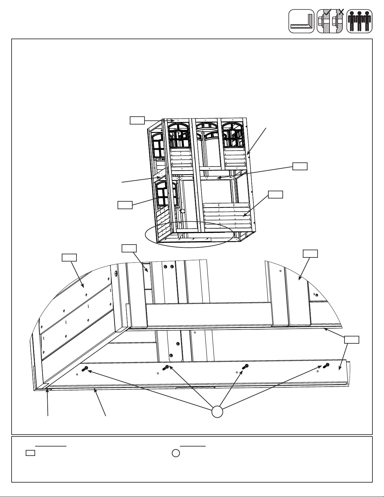
Step 6: Join Swing and Slide Wall Assemblies
Part 1
A: With at least two helpers lift the Slide Wall Assembly and Swing Wall Assembly so the (041) Narrow Back
Panel and (042) Narrow Front Panel meet with (052) Back Wall Panel and (051) Front Wall Panel and are tight
together as shown in g. 6.1.
B: Make sure the assembly is square then on the inside of the assembly, tight to (040) Slide End Panel and ush
to the bottom of the panels attach 1 (060) Floor Joist to (041) Narrow Back Panel and (052) Back Wall Panel
and a second (060) Floor Joist to (042) Narrow Front Panel and (051) Front Wall Panel with 4 (S7) #12 x 2” Pan
Screws per board. (g. 6.1 and 6.2)
Fig. 6.2
040
Fig. 6.1
Slide Wall
Assembly
041
041
042
Swing Wall
Assembly
052
051
051
060
S7
Tight
(both sides)
Wood Parts Hardware
060
2 x Floor Joist 1-1/4 x 3 x 40-3/4”
Flush
x 4 per board
S7
8 x #12 x2” Pan Screw
Page 27
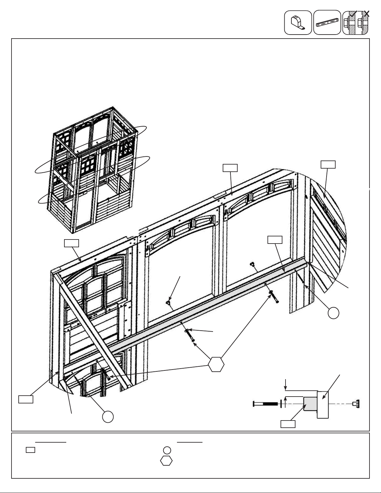
Step 6: Join Swing and Slide Wall Assemblies
Part 2
C: From inside the assembly, tight to both (040) Slide End Wall and (050) SW Wall Panel, halfway up the
assembly, 5/8” below the panel, loosely attach 1 (061) Side Joist to (041) Narrow Back Panel and (052) Back
Wall Panel with 3 (WB10) 5/16 x 2-5/8” Wafer Bolts (with at washer and t-nut). Bolts are installed from inside
the assembly. Make sure (061) Side Joist is level then attach with 2 (S3) #8 x 2-1/2” Wood Screws and tighten
bolts. (g. 6.3, 6.4 and 6.5)
D: Repeat Step C to attach 1 (061) Side Joist to (042) Narrow Front Panel and (051) Front Wall Panel. (g. 6.3
and 6.4)
Fig. 6.3
Fig. 6.4
Inside View
041
5/16”
T-Nut
052
5/16” Flat
Washer
050
061
Tight
S3
WB10
Fig. 6.5
Panel
5/8”
040
Tight
Wood Parts
061
2 x Side Joist 2 x 2 x 63”
S3
Hardware
S3
4 x #8 x 2-1/2” Wood Screw
WB10
6 x 5/16 x 2-5/8” Wafer Bolt
(5/16”atwasher,5/16”t-nut)
061
Page 28
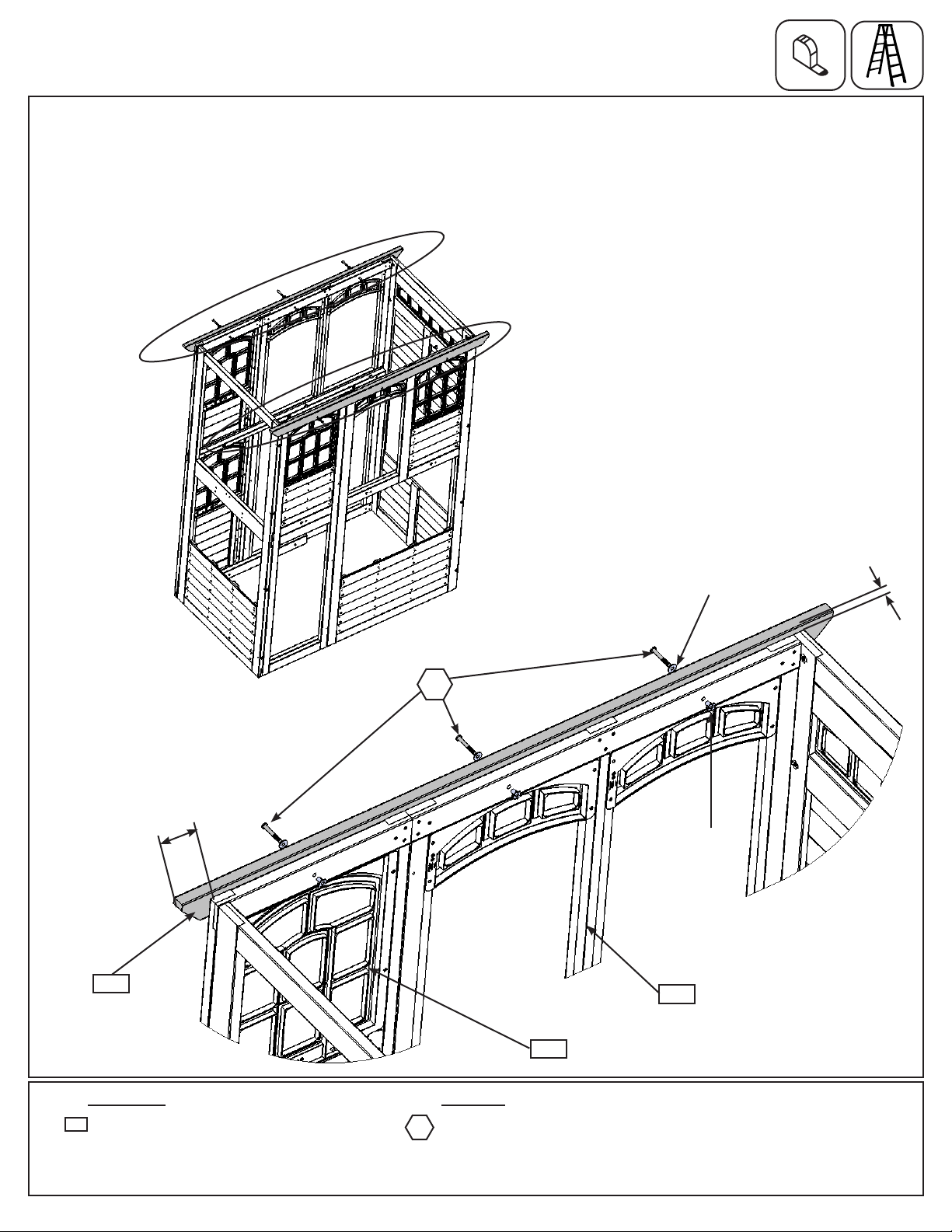
Step 6: Join Swing and Slide Wall Assemblies
Part 3
E: From outside the assembly, place 1 (062) Roof Support against (041) Narrow Back Panel and (052) Back
Wall Panel so it sits 3/4” above the panels and has approximately 3-1/16” overhang at each corner then attach
with 3 (WB8) 5/16 x 2-3/8” Wafer Bolts (with at washer and t-nut) . (g. 6.6 and 6.7)
F: Repeat Step E to attach 1 (062) Roof Support to (042) Narrow Front Panel and (051) Front Wall Panel. (g.
6.6 and 6.7)
Back Wall
Fig. 6.6
Fig. 6.7
Inside View
062
Approx
3-1/16”
Front Wall
WB8
5/16” Flat
Washer
052
3/4”
5/16”
T-Nut
041
Wood Parts
062
2 x Roof Support 1-1/4 x 3 x 72”
6 x 5/16 x 2-3/8” Wafer Bolt
(5/16”atwasher,5/16”t-nut)
Hardware
WB8
Page 29
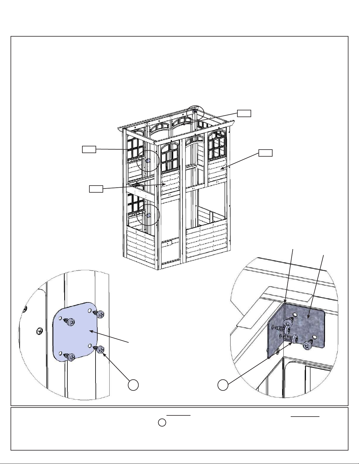
Step 6: Join Swing and Slide Wall Assemblies
Part 4
G: On the inside of the assembly attach (041) Narrow Back Panel to (052) Back Wall Panel using 2 Flat Panel
Brackets in the places shown with 4 (S8) #12 x 3/4” Pan Screws per bracket. (g. 6.8 and 6.9)
H: Repeat Step G to attach (042) Narrow Front Panel to (051) Front Wall Panel. (g. 6.8 and 6.9)
I: At all four corners, both top and bottom, attach 1 Panel Corner Bracket with 4 (S8) #12 x 3/4” Pan Screws per
bracket. Brackets to be ush to the top and bottom of the panels. (g. 6.8 and 6.10)
Fig. 6.9
Inside View
Fig. 6.8
041
042
Back Wall
Front Wall
052
051
Flush
Panel
Corner
Bracket
x 2 per wall
Fig. 6.10
Inside View
Flat Panel
Bracket
x 2 per wall
S8
x 4 per
bracket
Hardware
S8
48 x #12 x 3/4” Pan Screw
S8
x 4 per
bracket
Other Parts
4 x Flat Panel Bracket
8 x Panel Corner Bracket
Page 30
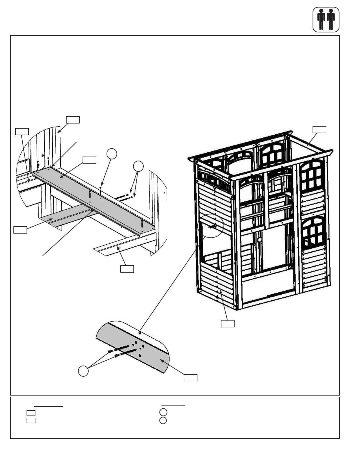
Step 7: Floor Assembly
Part 1
A: Place 1 (070) Floor Board tight to (040) Slide End Panel and 1 tight to (050) SW Wall Panel then attach each
to the (061) Side Joists with 4 (S20) #8 x 1-3/8” Wood Screws per board. (g. 7.1 and 7.2)
B: Place (071) Long Floor Joist tight to the bottom of each (070) Floor Board, centred over the pilot holes on the
(040) Slide End Panel and (050) SW Wall Panel then attach with 2 (S4) #8 x 3” Wood Screws per panel. Attach
(070) Floor Board to (071) Long Floor Joist with 2 (S20) #8 x 1-3/8” Wood Screws per board (g. 7.1, 7.2 and
7.3)
Fig. 7.2
061
071
Tight
040
Tight
070
S20
x 6 per
board
Fig. 7.1
040
S4
061
Wall removed
Fig. 7.3
050
for clarity
S4
050
Wood Parts
070
2 x Floor Board 1 x 5 x 35-5/8”
071
1 x Long Floor Joist 1-1/4 x 3 x 63-1/4”
Hardware
S20
12 x #8 x 1-3/8” Wood Screw
S4
4 x #8 x 3” Wood Screw
Page 31
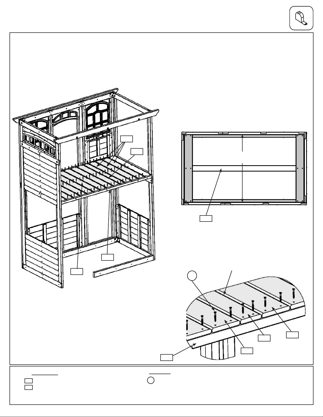
Step 7: Floor Assembly
Part 2
C: Measure the distance from the Back Wall to the Front Wall from the inside of the panels to make sure it
equals 35-3/4”. Maintain this measurement when installing the oor boards. Starting at the Slide Wall place 3
(070) Floor Boards tight to the previously attached (070) Floor Board, followed by 1 (072) Floor Board then 8
more (070) Floor Boards. Make sure all boards are equally spaced then attach to (071) Long Floor Joist and
each (061) Side Joist with 6 (S20) #8 x 1-3/8” Wood Screws per board. (g. 7.4, 7.5 and 7.6)
Fig. 7.4
Front Wall
070
072
Slide Wall
Fig. 7.5
071
Back Wall
35-3/4”
Front Wall
061
Fig. 7.6
Tight
070
Swing Wall
x 8
Back Wall
S20
x 6 per
board
Wall removed
for clarity
070
Wood Parts
070
11 x Floor Board 1 x 5 x 35-5/8”
072
1 x Floor Board 1 x 4 x 35-5/8”
061
Hardware
S20
72 x #8 x 1-3/8” Wood Screw
072
070
Page 32
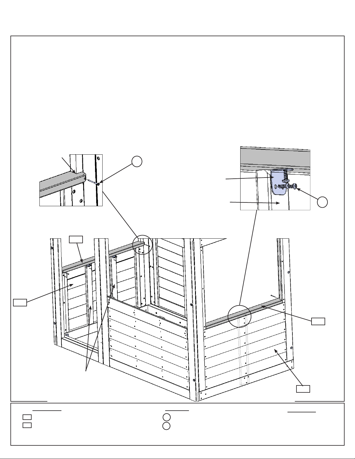
Step 8: Attach Wall Tops
A: In the opening of (050) SW Wall Panel, from the inside, attach (080) SW Wall Top, tight to the corner of the
panels with overhang facing in with 1 (S11) #8 x 2” Wood Screw at each end as shown in g. 8.1 and 8.2.
B: Attach (080) SW Wall Top to slat in (050) SW Wall Panel with 1 Corner Bracket using 3 (S13) #6 x 5/8” Pan
Screws. (g. 8.1 and 8.3)
C: In the opening of (040) Slide End Panel, from the inside, attach (081) Half Wall Top, tight to the corner of the
panels with overhang facing in with 1 (S11) #8 x 2” Wood Screw at each end as shown in g. 8.1 and 8.2.
D: Attach (081) Half Wall Top to slats in (040) Slide End Panel with 2 Corner Bracket using 3 (S13) #6 x 5/8”
Pan Screws per bracket. (g. 8.1 and 8.3)
Fig. 8.2
Inside View
Fig. 8.1
040
Tight
081
S11
x 1 per end
per board
Fig. 8.3
Inside View
Corner
Bracket
Slat
S13
x 3 per
bracket
080
Slat
050
Wood Parts
080
1 x SW Wall Top 5/4 x 3 x 33-1/2”
1 x Half Wall Top 5/4 x 3 x 33”
081
Hardware
S11
4 x #8 x 2” Wood Screw
S13
9 x #6 x 5/8” Pan Screw
Other Parts
3 x Corner Bracket
Page 33
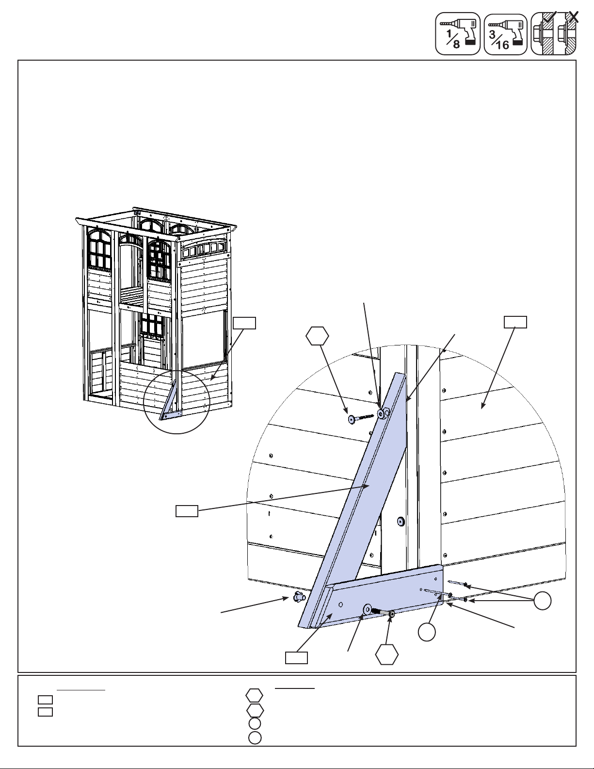
Step 9: Attach SW Ground and Diagonal
A: Loosely attach (090) SW Ground to (091) Diagonal with 1 (WB9) 5/16 x 2-1/8” Wafer Bolt (with at washer
and t-nut) then place (091) Diagonal tight and ush to the front of (050) SW Wall Panel. (090) SW Ground to be
ush to the bottom of (050) SW Wall Panel. (g. 9.1 and 9.2)
B: Pre-drill pilot hole with a 3/16” drill bit then attach (091) Diagonal to (050) SW Wall Panel with 1 (WL5) 1/4 x
2-1/2” Wafer Lag (with at washer), checking that it remains ush to outside edge. (g. 9.1 and 9.2)
C: Making sure bottom of (090) SW Ground is ush to bottom of (050) SW Wall Panel pre-drill with a 1/8” drill bit
then attach with 2 (S11) #8 x 2” Wood Screws and 1 (S4) #8 x 3” Wood Screw then tighten the bolt. (g. 9.1 and
9.2)
Fig. 9.1
091
050
WL5
5/16” Flat
Washer
Fig. 9.2
050
Flush
S11
5/16”
Wood Parts
090
1 x SW Ground 5/4 x 4 x 14-1/4”
091
1 x Diagonal 1-1/4 x 3 x 22”
T-Nut
090
5/16” Flat
Washer
WB9
Hardware
WB9
1x 5/16x2-1/8”WaferBolt(5/16”atwasher,5/16”t-nut)
WL5
1x 1/4x2-1/2”WaferLag(5/16”atwasher)
S4
1 x #8 x 3” Wood Screw
S11
2 x #8 x 2” Wood Screw
S4
Flush
Page 34
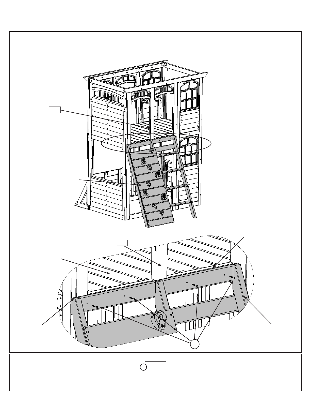
Step 10: Attach Access Ladder/Rockwall Assembly
Part 1
A: Place Access Ladder/Rockwall Assembly from Step 3 against (052) Back Wall Panel, ush to the outside
edge and ush to the top of the oor boards then attach with 4 (S11) #8 x 2” Wood Screws. (g. 10.1 and 10.2)
Fig. 10.1
052
Access Ladder/
Rockwall Assembly
Fig. 10.2
Floor
Boards
Flush
052
Flush
Access Ladder/
Rockwall Assembly
S11
Hardware
S11
4 x #8 x 2” Wood Screw
Page 35
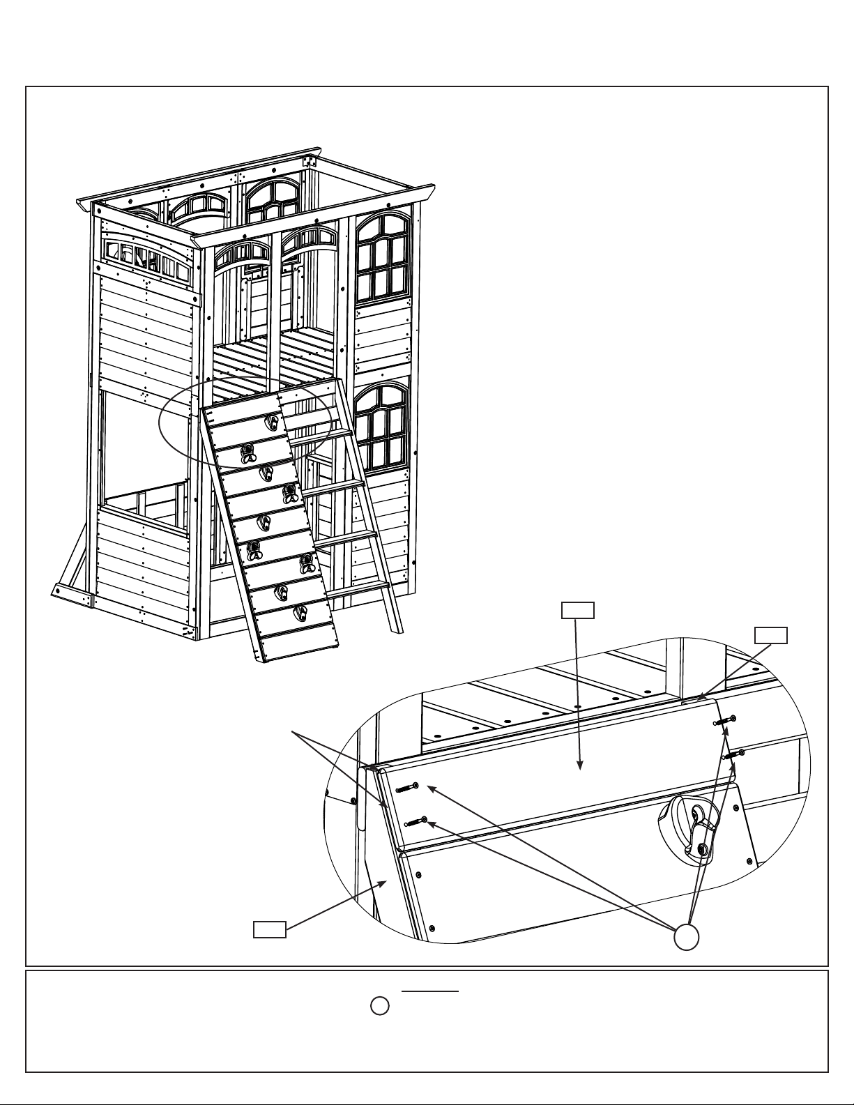
Step 10: Attach Access Ladder/Rockwall Assembly
Part 2
B: Place (031) Access Board from Step 3, Part 1 against (020) Left Access and (024) Rock Rail and ush to the
top then attach with 4 (S20) #8 x 1-3/8” Wood Screws. (g. 10.3 and 10.4)
Fig. 10.3
024
Flush
Hardware
S20
4 x #8 x 1-3/8” Wood Screw
Fig. 10.4
031
020
S20
Page 36
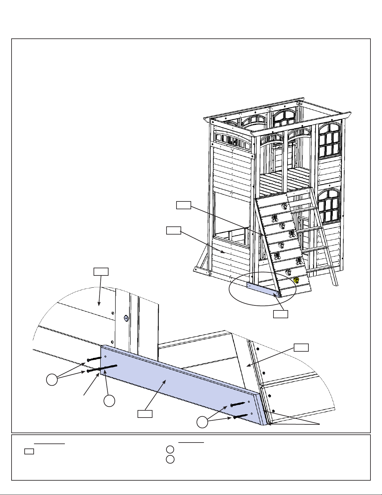
Step 10: Attach Access Ladder/Rockwall Assembly
Part 3
C: Place (100) RW-AL Ground Brace ush to the end and bottom of (024) Rock Rail. Make sure the other end
of the board is ush to the bottom of (050) SW Wall Panel then attach to (024) Rock Rail with 2 (S11) #8 x 2”
Wood Screws. (g. 10.5 and 10.6)
D: Attach other end of (100) RW-AL Ground Brace to (050) SW Wall Panel with 2 (S11) #8 x 2” Wood Screws
and 1 (S4) #8 x 3” Wood Screw. (g. 10.5 and 10.6)
Fig. 10.5
Fig. 10.6
S11
024
050
050
100
024
Flush
Wood Parts
100
1 x RW-AL Ground Brace 5/4 x 4 x 27-3/4”
S4
100
Hardware
S4
1 x #8 x 3” Wood Screw
S11
4 x #8 x 2” Wood Screw
S11
Flush
Page 37
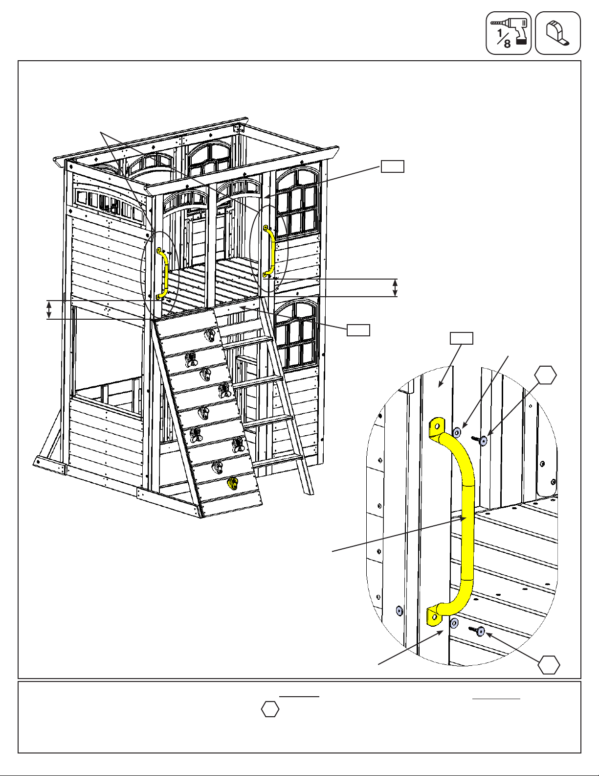
Step 11: Attach Steel Hand Grips to Fort
A: Measure 6” from the top of (025) RW/AL Support on (052) Back Wall Panel in the 2 places shown below,
pre-drill with a 1/8” drill bit then attach 2 Steel Hand Grips with 2 (WL3) 1/4 x 1-3/8” Wafer Lag (with at
washer) per Steel Hand Grip. (g. 11.1 and 11.2)
Steel Hand Grip
6”
Fig. 11.1
025
052
6”
052
1/4” Flat
Washer
Fig. 11.2
WL3
Steel
Hand
Grip
1/4” Flat
Washer
Hardware
4 x 1/4 x 1-3/8” Wafer Lag
WL3
(1/4”atwasher)
Other Parts
2 x Steel Hand Grip
WL3
Page 38
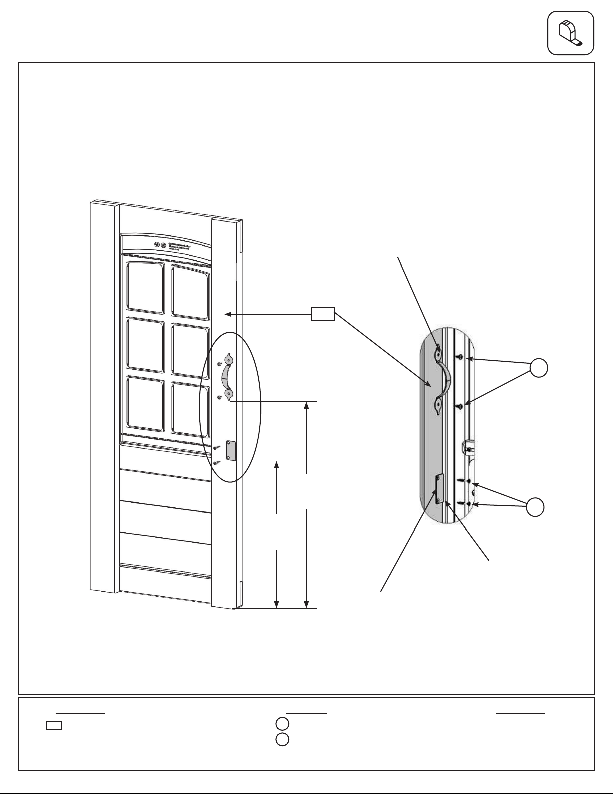
Step 12: Door Panel Assembly
Part 1
A: On the inside of (120) Door Window Panel measure 15” up from the bottom and attach Catch Plate ush to
the edge using 2 (S18) #6 x 1” Wood Screws. (g. 12.1 and 12.2)
B: On the inside of (120) Door Window Panel measure 22” up from the bottom and attach 1 Door Handle using
2 (S13) #6 x 5/8” Pan Screws. (g. 12.1 and 12.2)
Fig. 12.1
Door Handle
Fig. 12.2
120
Inside View
S13
22”
S18
15”
Flush
Catch Plate
Wood Parts
120
1 x Door Window Panel 1-1/4 x 15-3/4 x 42-1/8”
Hardware Other Parts
S18
2 x #6 x 1” Wood Screw
2 x #6 x 5/8” Pan Screw
S13
1 x Door Handle
1 x Catch Plate
Page 39
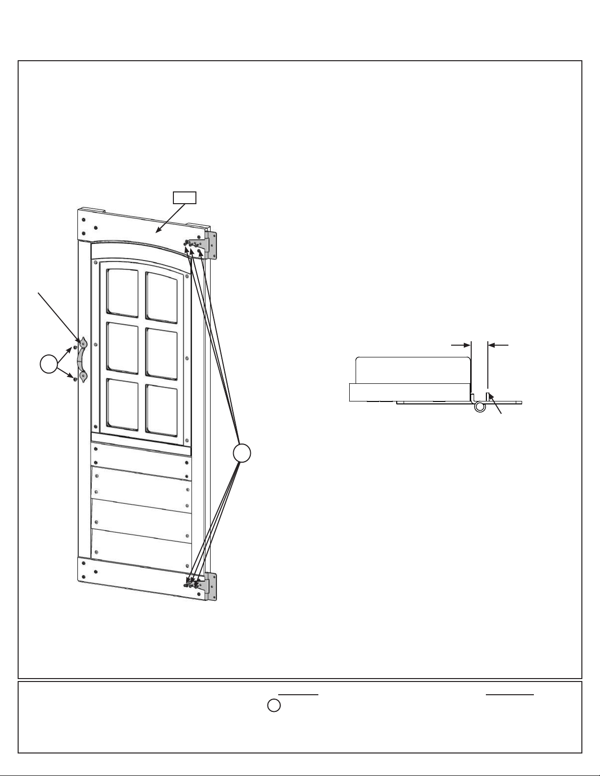
Step 12: Door Panel Assembly
Part 2
C: On the outside of the (120) Door Window Panel attach the second Door Handle at approximately the same
place as the one on the inside. Use 2 (S13) #6 x 5/8” Pan Screws. (g. 12.3)
D: Attach 2 Door Hinges on the outside of the (120) Door Window Panel on the opposite side from the Door
Handle. Judge spacing based on g. 12.3. Use 3 (S13) # 6 x 5/8” Pan Screws per Hinge.
Note: Hinge stops must be tight to (120) Door Window Panel. (g. 12.4)
Fig. 12.3
Door
Handle
S13
120
Fig. 12.4
Top View
1/2”
Hinge Stop
S13
Outside View
Hardware
S13
8 x #6 x 5/8” Pan Screw
Other Parts
1 x Door Handle
2 x Door Hinge
Page 40
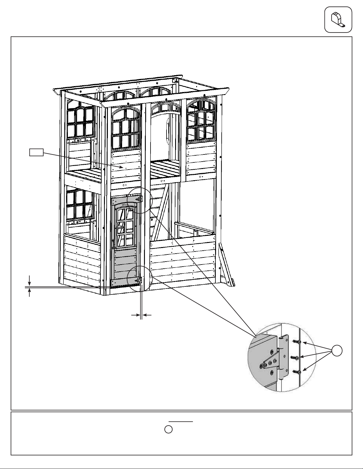
Step 12: Door Panel Assembly
Part 3
E: In the opening for the door, measure 3/4” from the top of (042) Narrow Front Panel bottom and maximum 5/8”
from right side of the opening which would be the Door Hinge side and attach the remaining side of the hinges to
(042) Narrow Front Panel using 3 (S13) #6 x 5/8” Pan Screws per hinge. (g. 12.5 and 12.6)
Fig. 12.5
042
3/4”
5/8”
Hardware
S13
6 x #6 x 5/8” Pan Screw
Fig. 12.6
S13
Page 41
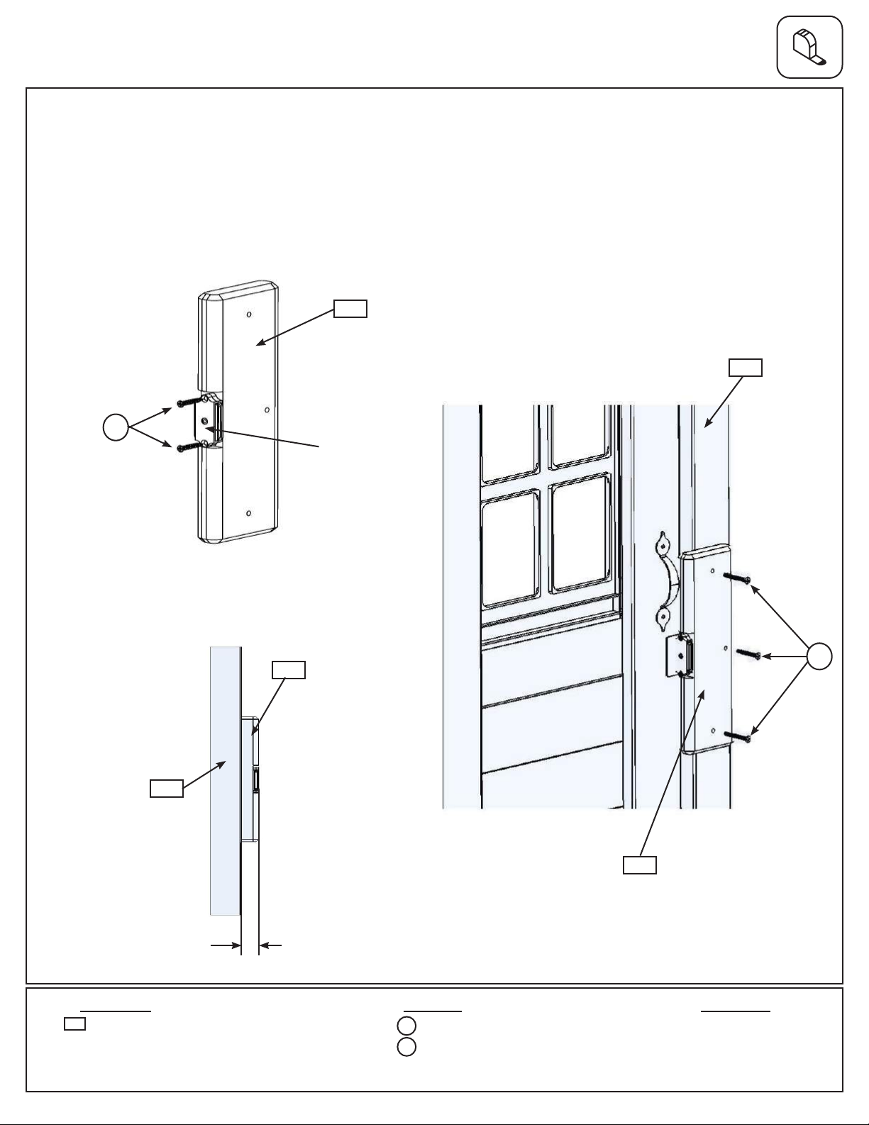
Step 12: Door Panel Assembly
Part 4
F: In the notched out opening of (121) Door Stop attach the Magnetic Catch using 2 (S18) #6 x 1” Wood Screws.
(g. 12.7) Important: Use a hand held screw driver and DO NOT over tighten.
G: On the inside of the assembly, attach (121) Door Stop to (042) Narrow Front Panel with 3 (S11) #8 x 2” Wood
Screws, making sure (121) Door Stop overhangs (042) Narrow Front Panel by 1-1/4” and is in position to receive
the Catch Plate. (g. 12.8 and 12.9).
Fig. 12.7
121
S18
Fig. 12.9
Side View
121
Magnetic Catch
Fig. 12.8
Inside View
042
S11
042
121
1-1/4”
Wood Parts
121
1 x Door Stop 5/4 x 3 x 10”
Hardware
S18
2 x #6 x 1” Wood Screw
S11
3 x #8 x 2” Wood Screw
Other Parts
1 x Magnetic Catch
Page 42
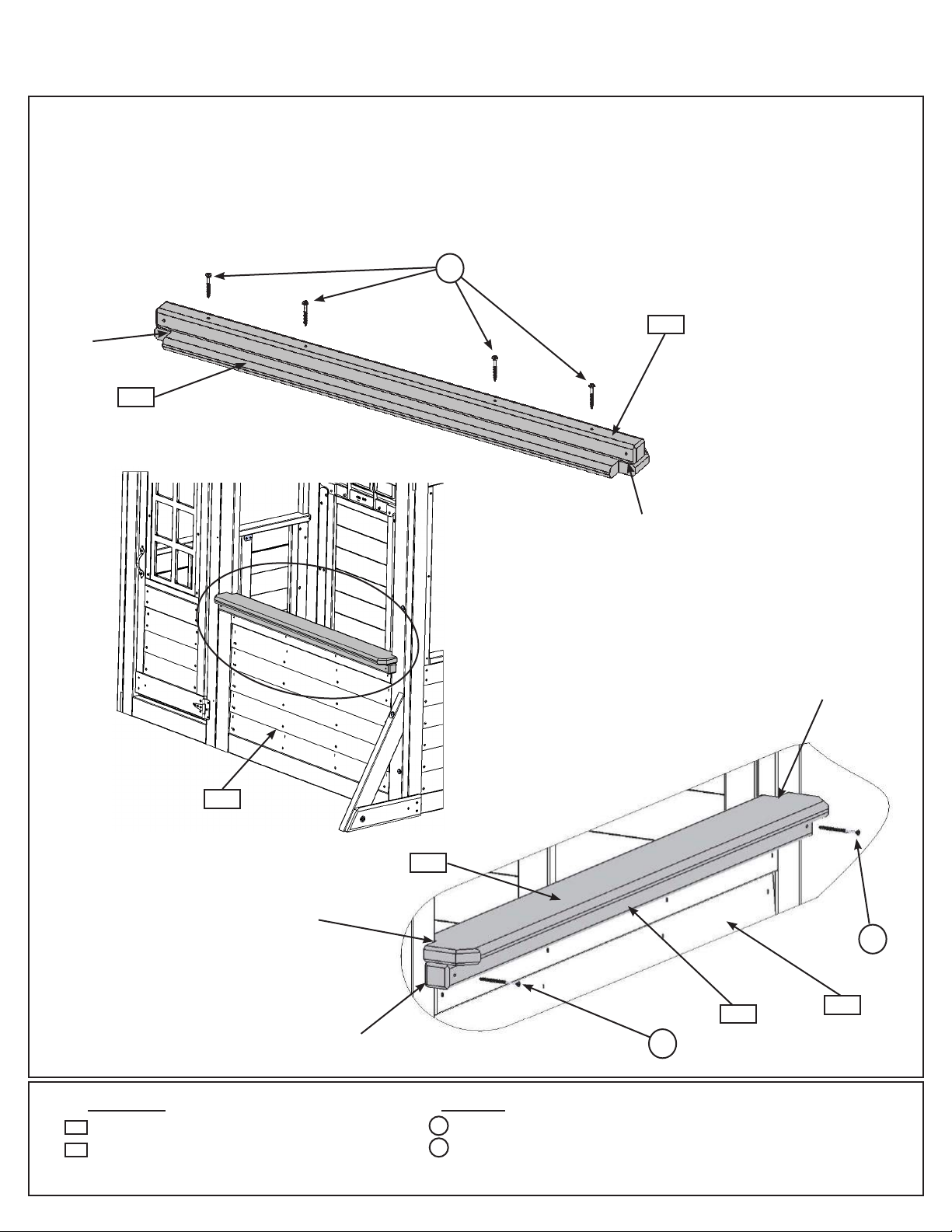
Step 13: Front Wall Assembly
Part 1
A: Place (130) Table Support ush to the notched out ends of (131) Table Top and attach with 4 (S7) #12 x 2”
Pan Screws as shown in g. 13.1.
B: Place Table Top Assembly tight in the opening of (051) Front Wall Panel and attach (130) Table Support to
(051) Front Wall Panel with 2 (S3) #8 x 2-1/2” Wood Screws. (g. 13.2 and 13.3)
Fig. 13.1
Flush
Fig. 13.2
131
S7
Flush
130
Fig. 13.3
Outside View
Tight
051
131
Tight
S3
130
Tight
Wood Parts
130
1 x Table Support 2 x 2 x 39-5/8”
131
1 x Table Top 5/4 x 5 x 39-5/8”
Hardware
S7
4 x #12 x 2” Pan Screw
S3
2 x #8 x 2-1/2” Wood Screw
S3
051
Page 43
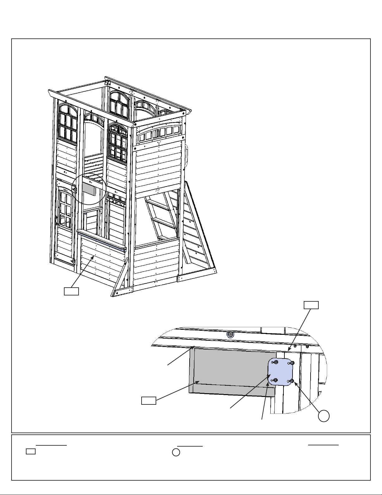
Step 13: Front Wall Assembly
Part 2
C: Place (132) Chalkwall Block tight to the top and left hand side of the opening in (051) Front Wall Panel
then place the Flat Panel Bracket against (132) Chalkwall Block and (051) Front Wall Panel. Attach Flat Panel
Bracket to (051) Front Wall Panel rst then to (132) Chalkwall Block with 4 (S8) #12 x 3/4” Pan Screws. (g. 13.4
and 13.5)
Fig. 13.4
051
Wood Parts
132
1 x Chalkwall Block 1-1/4 x 5 x 10”
Flush
and tight
132
Hardware
S8
4 x #12 x 3/4” Pan Screw
Fig. 13.5
Inside View
Flat Panel
Bracket
Tight
051
S8
x 4 per
bracket
Other Parts
1 x Flat Panel Bracket
Page 44
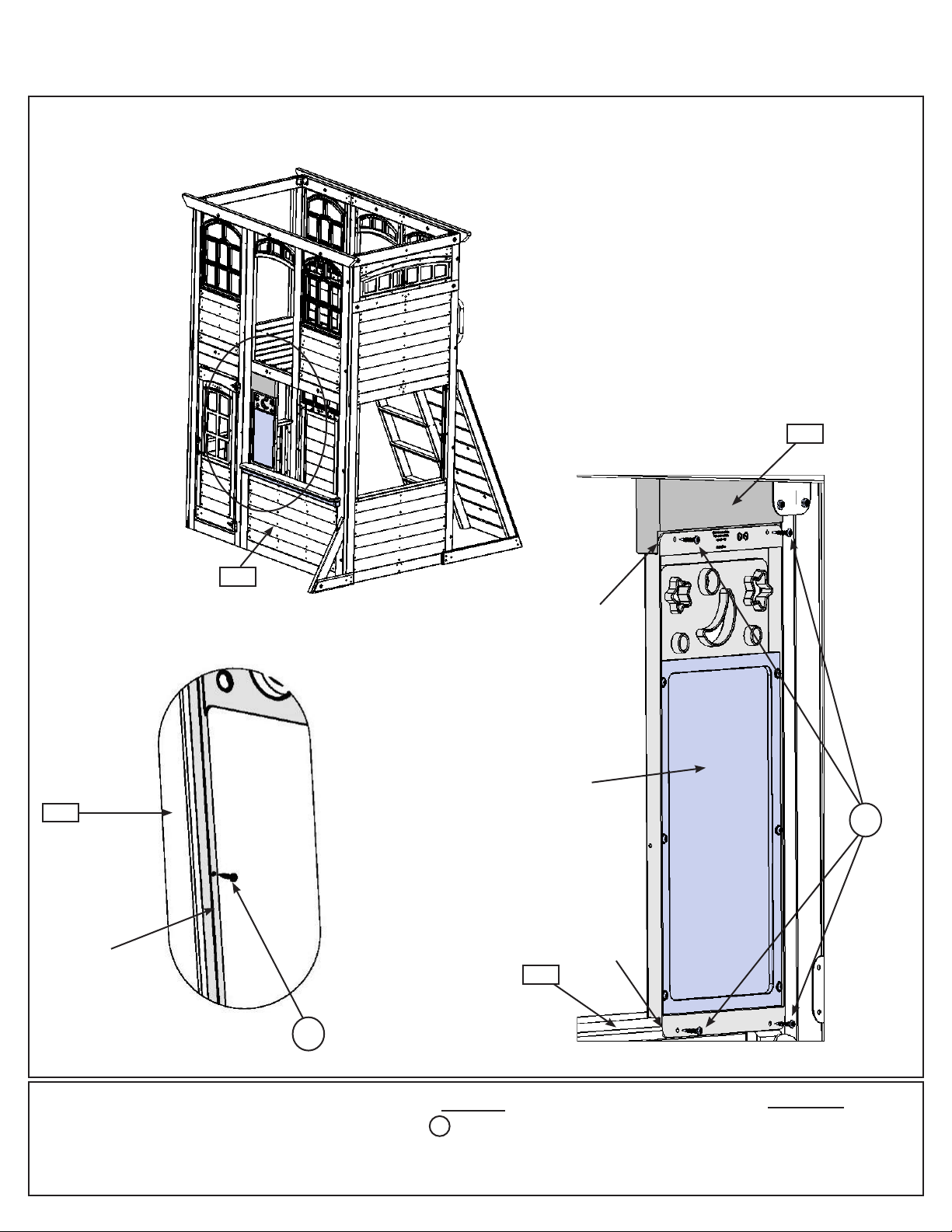
Step 13: Front Wall Assembly
Part 3
D: From inside the assembly place Sky Chalk Wall tight to (132) Chalkwall Block and (131) Table Top then
attach with 4 (S10) #8 x 1” Pan Screws from the inside and 1 (S10) #8 x 1” Pan Screw from the outside to the left
side of the (051) Front Wall Panel. (g. 13.6, 13.7 and 13.8)
Fig. 13.6
Fig. 13.8
Outside View
051
051
Tight
Sky
Chalk
Wall
Fig. 13.7
Inside View
132
S10
Sky
Chalk
Wall
S10
Hardware
S10
5 x #8 x 1” Pan Screw
131
Tight
Other Parts
1 x Sky Chalk Wall
Page 45
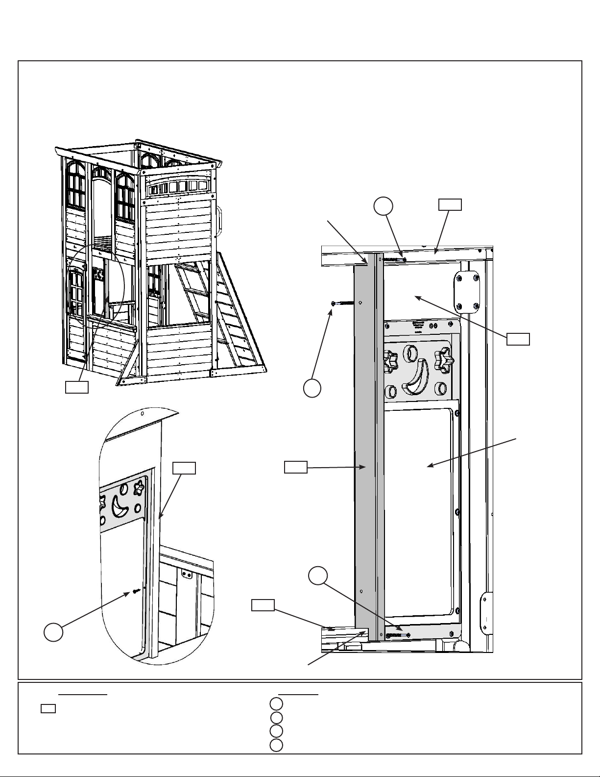
Step 13: Front Wall Assembly
Part 4
E: From inside the assembly place (133) Chalkwall Side tight to (051) Front Wall Panel, (131) Table Top and
(132) Chalkwall Block. Attach to (132) Chalkwall Block rst from the side with 1 (S3) #8 x 2-1/2” Wood Screw
then from the inside to (051) Front Wall Panel with 1 (S20) #8 x 1-3/8” Wood Screw and (131) Table Top with 1
(S11) #8 x 2” Wood Screw. From the outside attach Sky Chalkwall to (133) Chalkwall Side with 1 (S10) #8 x 1”
Pan Screw. (g. 13.9, 13.10 and 13.11)
Fig. 13.9
Fig. 13.10
Inside View
S20
Tight
051
133
Fig. 13.11
Outside View
133
132
S3
Sky
Chalk
Wall
133
S11
131
S10
Tight
Wood Parts
133
1 x Chalkwall Side 1 x 2 x 27-7/16”
Hardware
S11
1 x #8 x 2” Wood Screw
S3
1 x #8 x 2-1/2” Wood Screw
S10
1 x #8 x 1” Pan Screw
S20
1 x #8 x 1-3/8” Wood Screw
Page 46
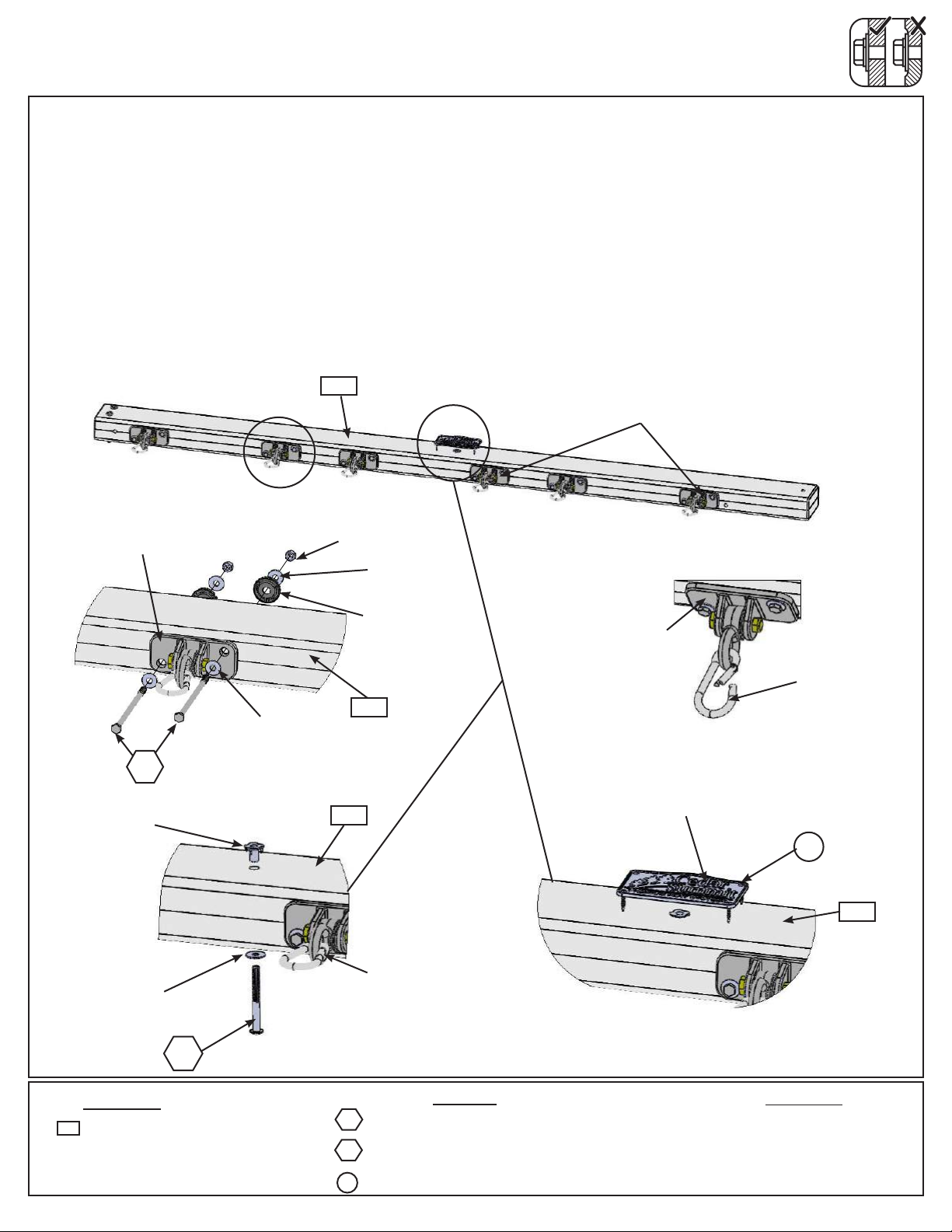
Step 14: Swing Beam Assembly
Part 1
A: Attach 6 Heavy Duty Swing Hangers to (140) Engineered SW Beam using 2 (G13) 5/16 x 6-1/8” Hex Bolt
(with 2 at washers, plastic formed washer and lock nut) per swing hanger, as shown in g. 14.1 and 14.2.
B: Attach 1 Spring Loaded Quick Link to each Heavy Duty Swing Hanger. (g. 14.3)
C: Install 1 (WB7) 5/16 x 3” Wafer Bolt (with at washer and t-nut) in the middle bolt hole, from the bottom
up, in (140) Engineered SW Beam as shown in g. 14.1 and 14.4. IT IS IMPORTANT THAT THIS BOLT IS
ATTACHED. IT WILL MINIMIZE CHECKING OF WOOD.
D: Attach Cedar Summit Plaque to centre of (140) Engineered SW Beam (over top of t-nut) using 4 (S18) #6 x
1” Wood Screws. (g. 14.5)
Fort End
Fig. 14.2
Heavy Duty
Swing Hanger
G13
5/16”
T-Nut
5/16” Flat
Washer
140
5/16”
Lock Nut
140
5/16” Flat
Washer
Plastic
Formed
Washer
140
Heavy Duty
Fig. 14.1
Swing Hanger x 6
Swing End
Fig. 14.3
Heavy Duty
Swing Hanger
Spring
Loaded
Quick Link
Caution: The Spring Loaded Quick Link
must be attached to the Heavy Duty Swing
Hanger in the closed position. (g. 14.4)
Cedar Summit
Plaque
Fig. 14.5
S18
x 4
Fig. 14.4
140
Spring Loaded Quick
5/16” Flat
Washer
WB7
Wood Parts
140
1 x Engineered SW Beam 4 x 6 x 92”
12 x 5/16 x 6-1/8” Hex Bolt
(5/16”atwasherx2,5/16”locknut&plasticformedwasher)
1 x 5/16 x 3” Wafer Bolt
(5/16”atwasher,5/16”t-nut)
4 x #6 x 1” Wood Screw
Link in the closed
position
G13
WB7
S18
Hardware
Other Parts
6 x Heavy Duty Swing Hangers
6 x Spring Loaded Quick Link
1 x Cedar Summit Plaque
Page 47
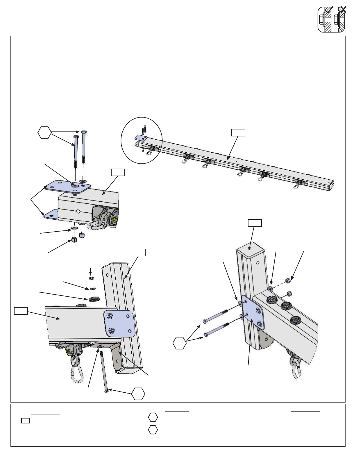
Step 14: Swing Beam Assembly
Part 2
E: On the Fort End of (140) Engineered SW Beam attach 2 Heavy Flat Brackets with 2 (G21) 5/16 x 3-3/4”
Hex Bolts (with 2 at washers and 1 lock nut). (g. 14.6 and 14.7)
F: Place (141) SW Mount in between both Heavy Flat Brackets and place 1 Heavy L-Bracket against (140)
Engineered SW Beam and (141) SW Mount. Attach with 1 (G17) 3/8 x 6” Hex Bolt (with 2 at washers, plastic
formed washer and lock nut). (g. 14.8)
G: Attach (141) SW Mount to Heavy Flat Brackets with 2 (G21) 5/16 x 3-3/4” Hex Bolts (with 2 at washers
and 1 lock nut). (g. 14.9)
Fort End
Fig. 14.6
Fig. 14.7
5/16” Flat
Washer
G21
140
140
Heavy
Flat
Bracket
5/16” Flat
Washer
Plastic
Formed
Washer
140
Fig. 14.8
5/16”
Lock Nut
3/8” Flat
Washer
3/8”
Lock Nut
141
G21
5/16” Flat
Washer
141
5/16” Flat
Washer
5/16”
Lock Nut
Fig. 14.9
Heavy
Bracket
L-Bracket
Heavy Flat
3/8” Flat
Washer
Wood Parts
141
1 x SW Mount 4 x 4 x 16”
G17
Hardware
G21
4 x 5/16 x 3-3/4” Hex Bolt
(5/16”atwasherx2,5/16”locknut)
G17
1 x 3/8 x 6” Hex Bolt
(3/8”atwasherx2,plasticformedwasher&3/8”locknut)
Other Parts
2 x Heavy Flat Bracket
1 x Heavy L-Bracket
Page 48
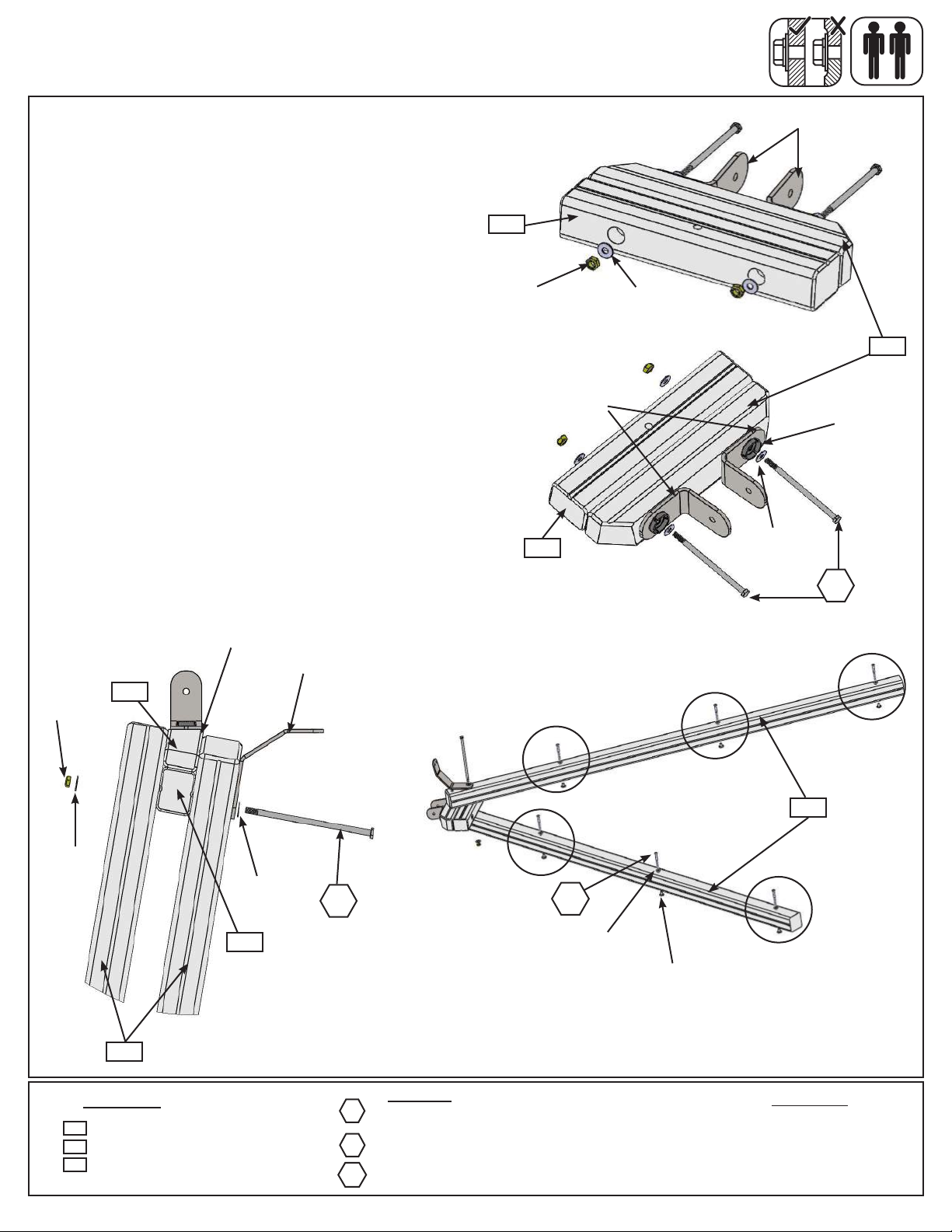
Step 15: Swing Post Assembly
Part 1
Note: Keep all bolts from Step 15 series loose
until start of Step 17
A: Place (150) SW Block Angle on top of (151)
Block SW and attach 2 Heavy L-Brackets on top of
(150) SW Block Angle feeding 2 (G17) 3/8 x 6” Hex
Bolts (with 2 at washers, plastic formed washer and
lock nut) through both boards as shown in g. 15.1
and 15.2.
B: Attach 3 (WB7) 5/16 x 3” Wafer Bolts (with at
washer and t-nut) to all three holes in each (152)
SW Post as shown in g. 15.3. IMPORTANT!
MAKE SURE ALL 6 BOLTS ARE ATTACHED TO
MINIMIZE CHECKING OF WOOD.
C: Place (150) SW Block Angle and (151) Block
SW assembly in between 2 (152) SW Post (Heavy
L-Brackets towards the outside). Place 1 Heavy
C-Bracket on the top (152) SW Post and attach with
(G26) 3/8 x 9-1/4” Hex Bolt (with 2 at washers and
1 lock nut), as shown in g. 15.4.
Fig. 15.1
Bottom View
151
3/8”
Lock
Nut
Fig. 15.2
Top View
151
Heavy L-Bracket
3/8” Flat
Washer
150
Heavy
L-Bracket
Plastic
Formed
Washer
3/8” Flat
Washer
G17
3/8” Lock
Nut
3/8” Flat
Washer
Fig. 15.4
150
152
Notice Angle
Orientation
Heavy C-Bracket
3/8” Flat
Washer
151
G26
Fig. 15.3
WB7
152
x 6
5/16” Flat
Washer
5/16” T-Nut
Wood Parts
150
1 x SW Block Angle 2-1/2 x 3 x 15”
151
1 x Block SW 2-1/2 x 3 x 15”
152
2 x SW Post 4 x 4 x 92”
2 x 3/8 x 6” Hex Bolt
Hardware
G17
(3/8”atwasherx2,plasticformedwasher&3/8”locknut)
1 x 3/8 x 9-1/4” Hex Bolt
G26
(3/8”atwasherx2&3/8”locknut)
WB7
6 x 5/16 x 3” Wafer Bolt
(5/16”atwasher&5/16”t-nut)
Other Parts
2 x Heavy L-Bracket
1 x Heavy C-Bracket
Page 49
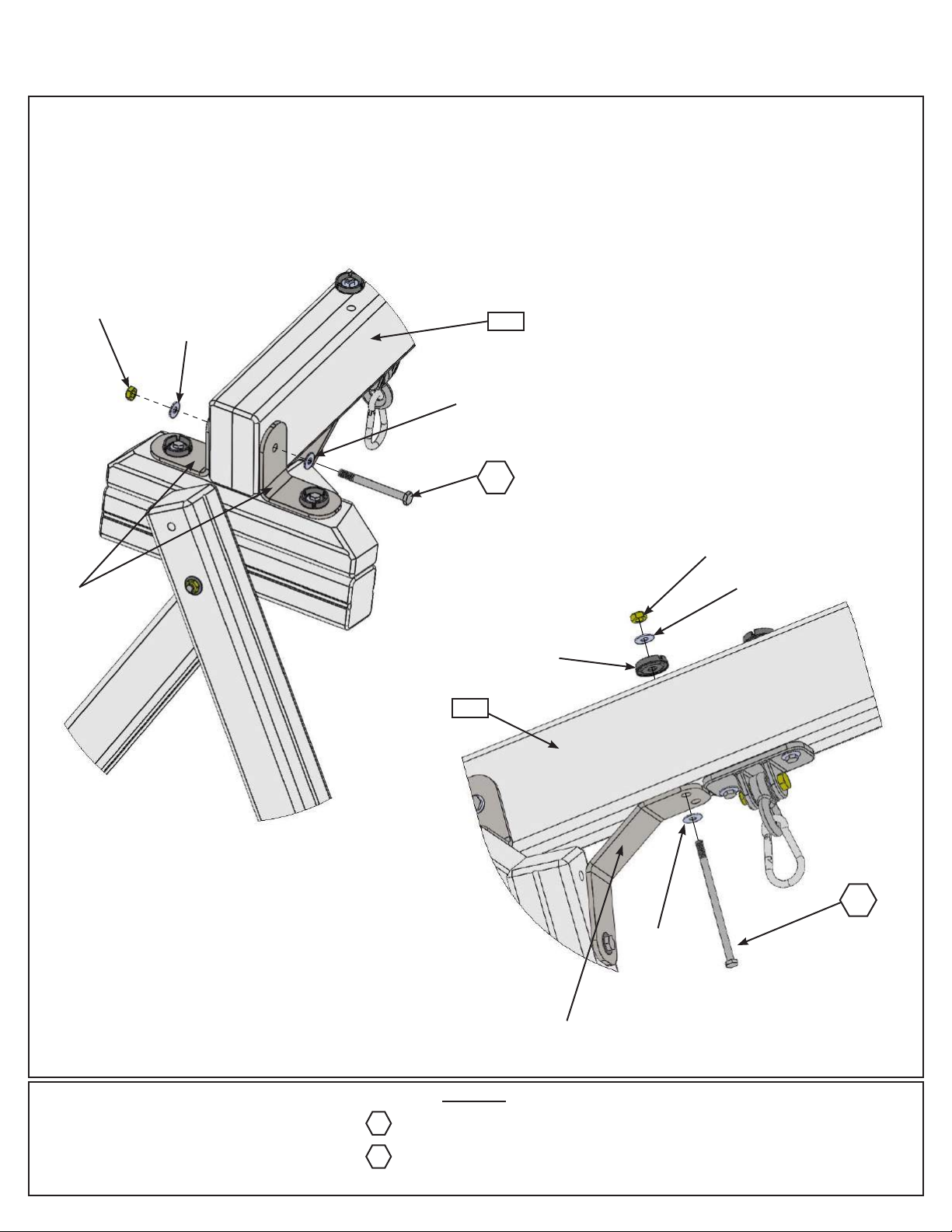
Step 15: Swing Post Assembly
Part 2
D: Place Swing End of (140) Engineered SW Beam in between Heavy L-Brackets assembled in Step A making
sure holes are lined up then attach Swing Post Assembly to Swing Beam Assembly using 1 (G20) 3/8 x 4” Hex
Bolt (with 2 at washers and lock nut) through Heavy L-Bracket. (g. 15.5)
E: Attach (140) Engineered SW Beam to Heavy C-Bracket with 1 (G17) 3/8 x 6” Hex Bolt (with 2 at washers,
plastic formed washer and lock nut). (g. 15.6)
Fig. 15.5
3/8” Lock
Nut
3/8” Flat
Washer
140
3/8” Flat
Washer
G20
Heavy
L-Bracket
Fig. 15.6
3/8” Lock Nut
3/8” Flat
Washer
Plastic
Formed
Washer
140
G17
3/8” Flat
Washer
Heavy C-Bracket
Hardware
1 x 3/8 x 6” Hex Bolt
G17
(3/8”atwasherx2,plasticformedwasher&3/8”locknut)
1 x 3/8 x 4” Hex Bolt
G20
(3/8”atwasherx2&3/8”locknut)
Page 50
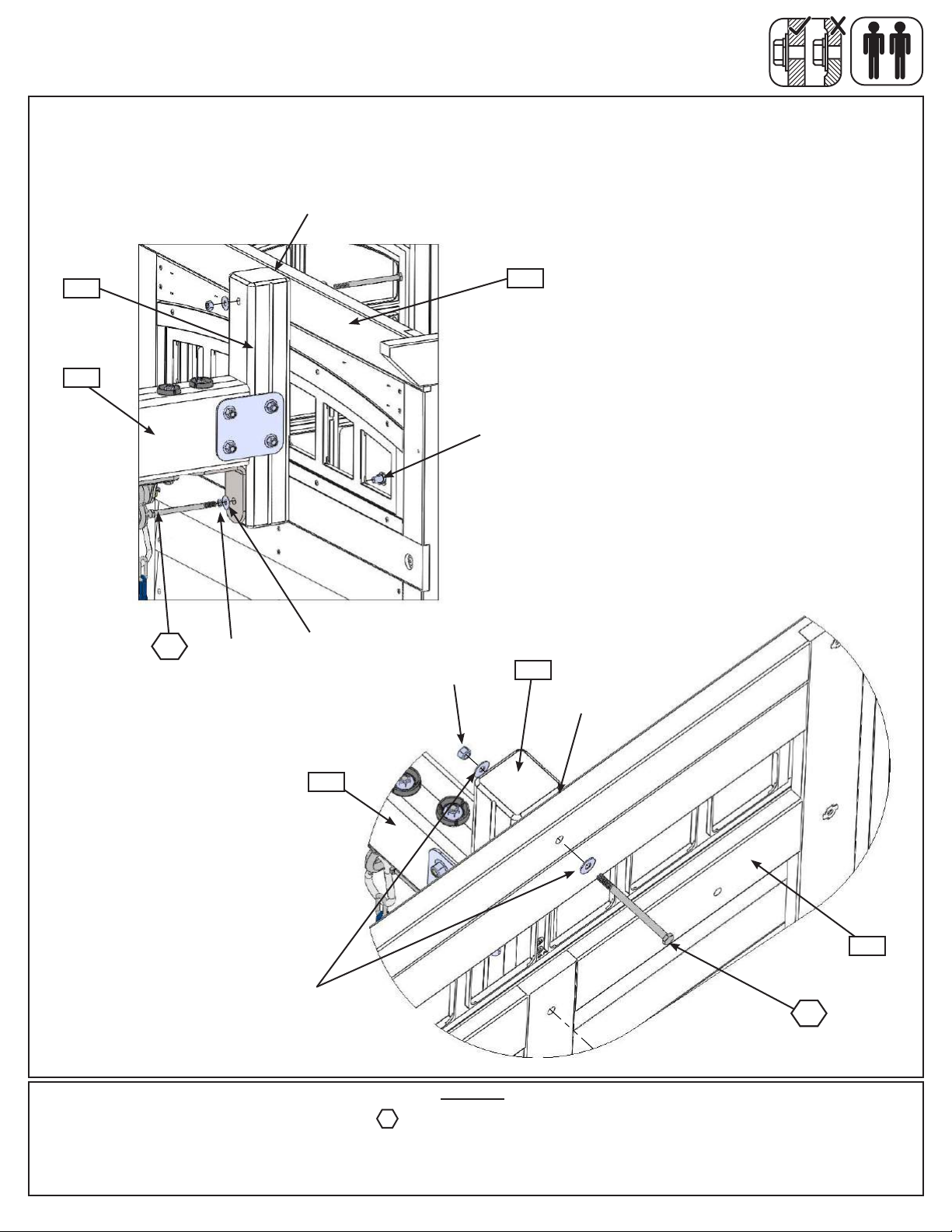
Step 15: Swing Post Assembly
Part 3
F: Place (141) SW Mount ush to the top of (050) SW Wall Panel. Attach with 1 (G5) 5/16 x 4-1/2” Hex Bolt
(with lock washer, at washer and t-nut) in the bottom hole from outside the assembly and 1 (G5) 5/16 x 4-1/2”
Hex Bolt (with 2 x at washer and 1 lock nut) in the top hole from inside the assembly. (g. 15.7 and 15.8)
Flush
Fig. 15.7
141
140
G5
5/16” Lock
Washer
5/16” Flat
Washer
5/16”
T-Nut
5/16” Lock Nut
050
Fig. 15.8
141
Flush
140
050
5/16” Flat
Washer
Hardware
G5
2 x 5/16 x 4-1/2” Hex Bolt
(1-5/16”lockwasher,5/16”atwasher,5/16”t-nut)
(1-5/16”atwasherx2,5/16”locknut)
G5
Page 51
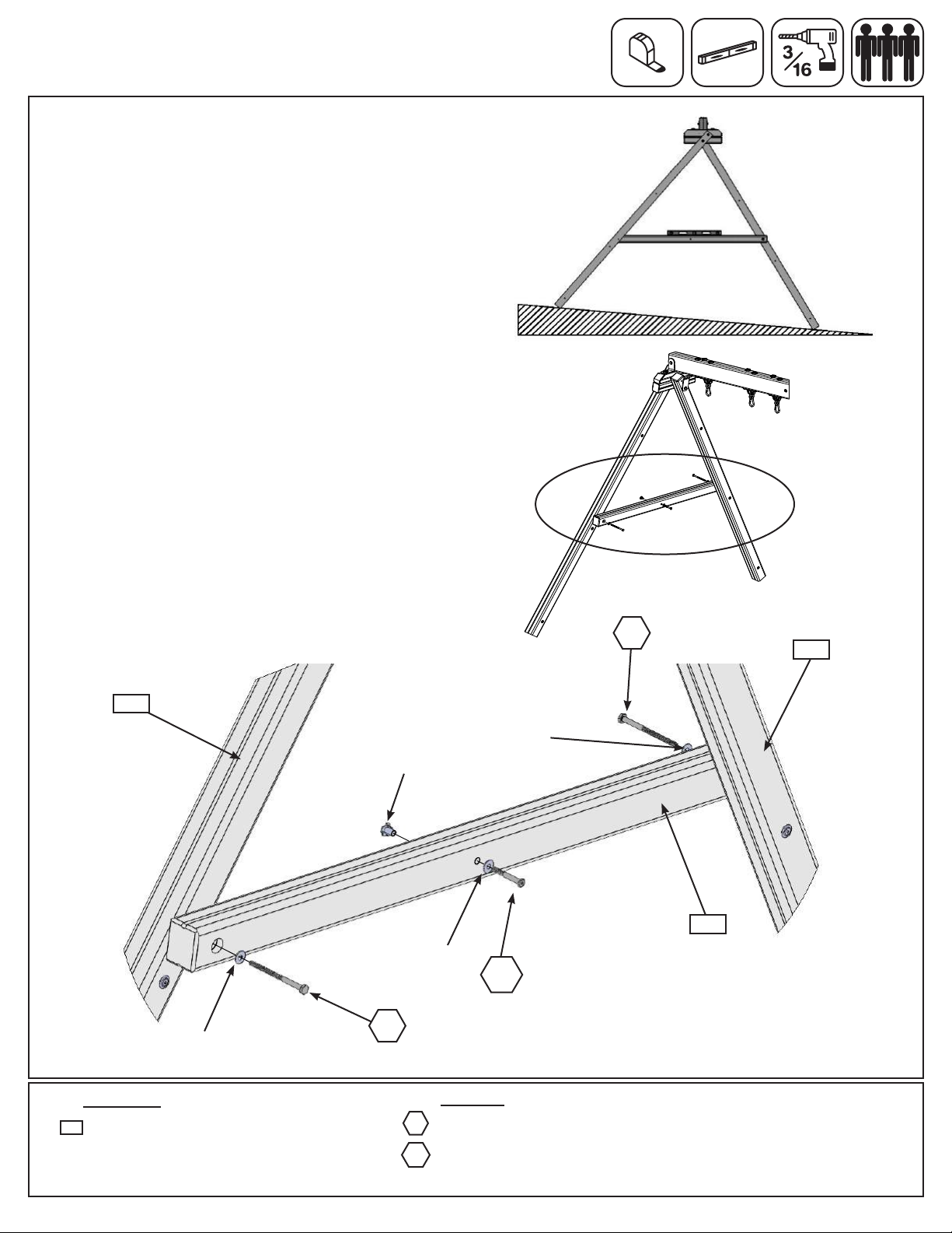
Step 16: Attach Cross Support
Pre-drill all holes using a 3/16” drill bit before
installing the lag screws.
A: To adjust for uneven ground, raise or lower the
(160) Support Cross on the (152) SW Post. Make sure
the Support Cross is level prior to attaching with the lag
screws. (g. 16.1 and 16.2)
B: Place (160) Support Cross between (152) SW
Posts at the previously determined spot and fasten with
1 (LS9) 5/16 x 4-3/4” Lag Screw (with at washer) per
side. (g. 16.2 and 16.3) Notice one side is fastened
on the outside and one on the inside. It is important
that each side is positioned exactly the same as the
diagram.(g.16.3)Tightenthelagscrewwhen
youaresure(160)SupportCrossislevel.
C: Attach 1 (WB8) 5/16 x 2-3/8” Wafer Bolt (with at
washer and t-nut) to (160) Support Cross through
the middle hole. (g. 16.2 and 16.3) IMPORTANT!
MAKE SURE THE BOLT IS ATTACHED TO MINIMIZE
CHECKING OF WOOD.
Fig. 16.1
Fig. 16.2
152
Fig. 16.3
5/16” Flat
Washer
5/16” T-Nut
5/16” Flat
Washer
LS9
LS9
152
5/16” Flat
Washer
160
WB8
Wood Parts
160
1 x Support Cross 2-1/2 x 3 x 51”
2 x 5/16 x 4-3/4” Lag Screw
(5/16”atwasher)
1 x 5/16 x 2-3/8” Wafer Bolt
(5/16”atwasher,5/16”t-nut)
Hardware
LS9
WB8
Page 52
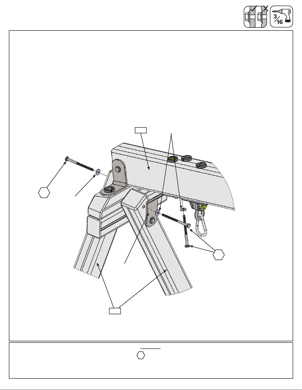
Step 17: Final Swing Post Assembly
Pre-drill all holes using a 3/16” drill bit before installing the lag screws.
Note: Tighten all bolts from Step 15 series before installing lag screws.
A: Attach 1 (LS9) 5/16 x 4-3/4” Lag Screw (with at washer) into each (152) SW Post, as shown in g. 17.1.
B: Attach 1 (LS9) 5/16 x 4-3/4” Lag Screw (with at washer) into remaining hole of the Heavy C-Bracket into
(140) Engineered SW Beam. (g. 17.1)
LS9
Fig. 17.1
5/16” Flat
Washer
Heavy C-Bracket
140
5/16” Flat
Washer
LS9
152
Hardware
LS9
3 x 5/16 x 4-3/4” Lag Screw
(5/16”atwasher)
Page 53
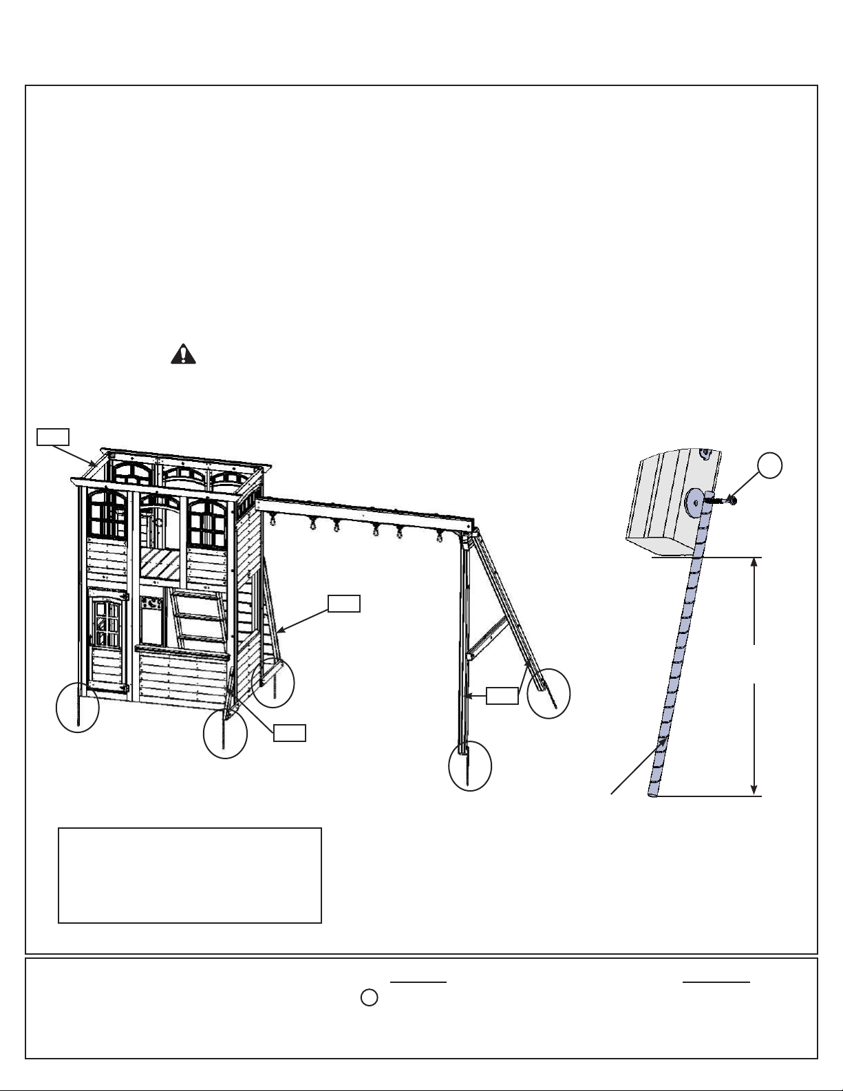
Step 18: Install Ground Stakes
MOVE FORT TO FINAL LOCATION PRIOR TO STAKING
FINAL LOCATION MUST BE LEVEL GROUND
A: In the 5 places shown in g. 18.1 drive the Rebar Ground Stakes 13” into the ground against (040) Slide End
Panel, on the Front, (091) Diagonal, (024) Rock Rail and both (152) SW Posts. Be careful not to hit the washer
while hammering stakes into the ground as this could cause the washer to break o.
B: Attach ground stakes using 1 (S7) #12 x 2” Pan Screw per ground stake as shown in g. 18.2.
C: After driving stakes into the ground, check for sharp edges caused by the impact of the hammer. Smooth any
sharp edges from impact area and touch up with outdoor paint.
Warning! To prevent tipping and avoid potential injury, stakes must
be driven 13” into ground. Digging or driving stakes can be dangerous if you
donotcheckrstforunder-groundwiring,cablesorgaslines.
Fig. 18.1
040
Front
091
SEE FRONT COVER FOR
SAFETY CLEARANCE
Fig. 18.2
S7
021
13”
In Ground
152
Rebar Ground
Stake
Hardware
S7
5 x #12 x 2” Pan Screw
Other Parts
5 x Rebar Ground Stake
Page 54
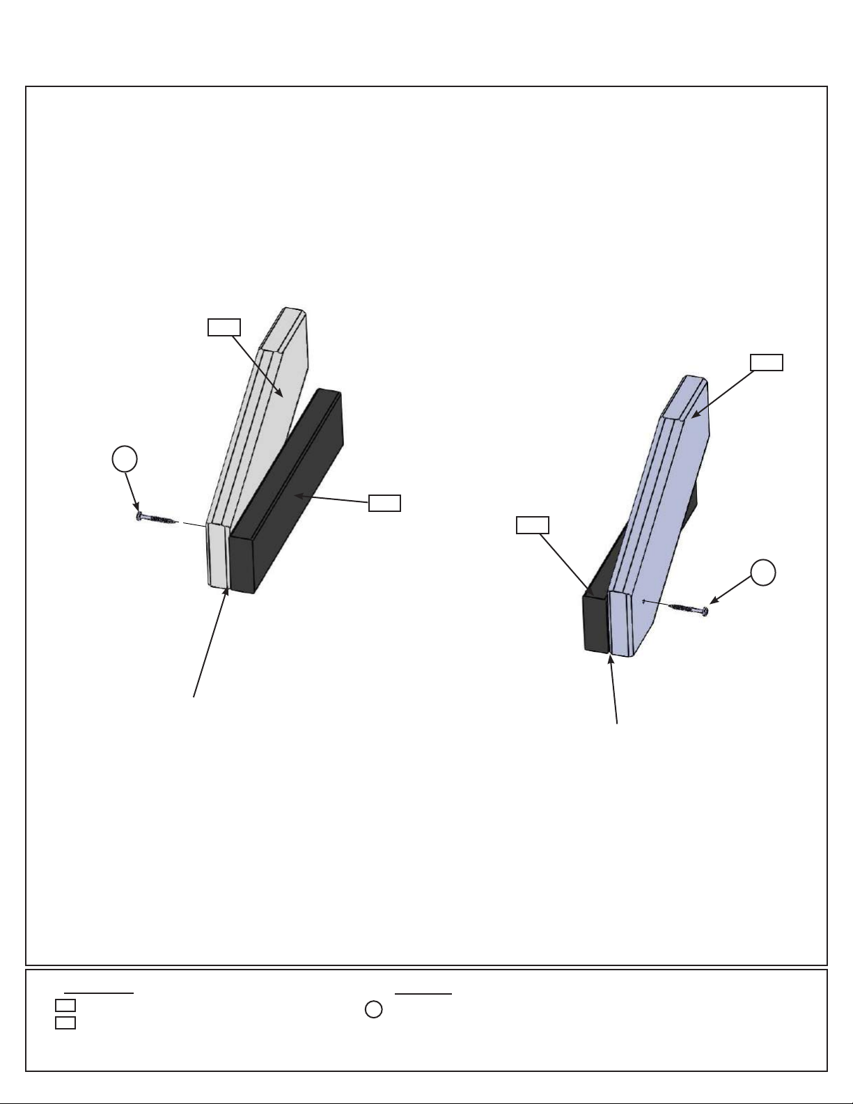
Step 19: Lower Crowsnest Assembly
Part 1
A: Attach 1 (190) Crowsnest Gusset to 1 (191) Crowsnest Joist so the bottoms and ends are ush with 1 (S7)
#12 x 2” Pan Screw. Repeat to make a second set with the (191) Crowsnest Joist on the opposite side from the
rst. (g. 19.1 and 19.2)
Fig. 19.1
S7
Flush
190
Fig. 19.2
190
191
191
S7
Flush
Wood Parts
190
2 x Crowsnest Gusset 2 x 6 x 15”
191
2 x Crowsnest Joist 2 x 4 x 13-1/2”
2 x #12 x 2” Pan Screw
Hardware
S7
Page 55
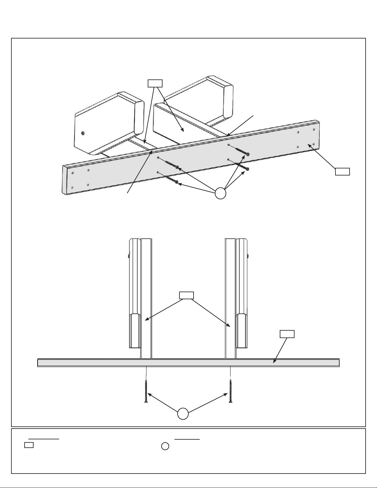
Step 19: Lower Crowsnest Assembly
Part 2
B: Place (192) Crowsnest Back against the ends of (191) Crowsnest Joists so the tops are ush then attach with
4 (S3) #8 x 2-1/2” Wood Screws. (g. 19.3 and 19.4)
191
Fig. 19.3
Flush
192
Fig. 19.4
Top View
Flush
S3
191
192
S3
Wood Parts
192
1 x Crowsnest Back 5/4 x 4 x 34”
4 x #8 x 2-1/2” Wood Screw
Hardware
S3
Page 56
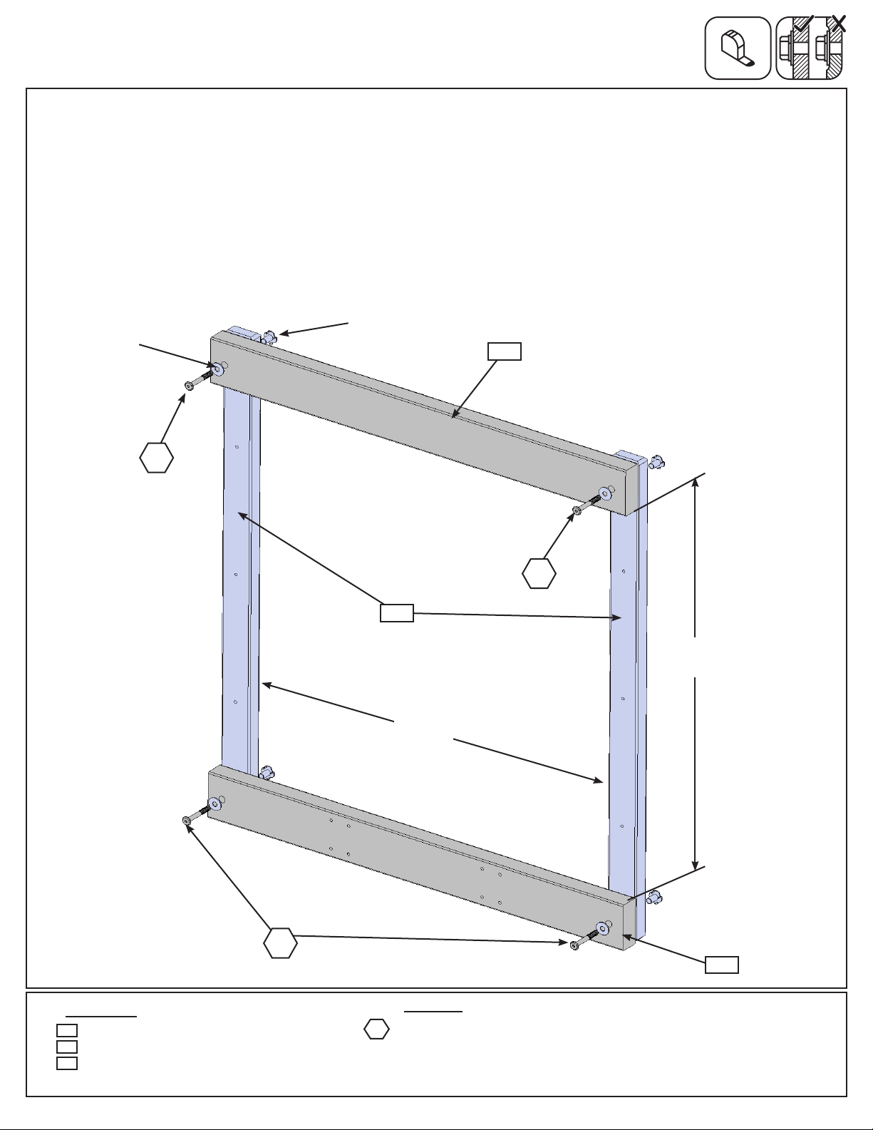
Step 20: Upper Crowsnest Assembly
Part 1
A: Loosely attach (200) Crowsnest Top to 2 (201) Upright Crowsnest using 2 (WB9) 5/16 x 2-1/8” Wafer Bolts
(with at washer and t-nut). The distance between uprights must be 25-1/2”. (g. 20.1)
B: Loosely attach (202) Crowsnest Front to each (201) Upright Crowsnest using 2 (WB9) 5/16 x 2-1/8” Wafer
Bolts (with at washer and t-nut). The distance between (200) Crownest Top and (202) Crowsnest Front must be
27-5/8” (g. 20.1)
C: Double check the dimensions then tighten the bolts. It is important these dimensions are met so there are no
issues in future steps.
5/16”
5/16” Flat
Washer
WB9
T-Nut
200
Fig. 20.1
WB9
WB9
201
27-5/8”
25-1/2”
202
Wood Parts
200
1 x Crowsnest Top 2 x 4 x 29-1/2”
201
2 x Upright Crowsnest 1 x 2 x 34-1/8”
202
1 x Crowsnest Front 2 x 4 x 29-1/2”
4 x 5/16 x 2-1/8” Wafer Bolt
(5/16”atwasher,5/16”t-nut)
Hardware
WB9
Page 57
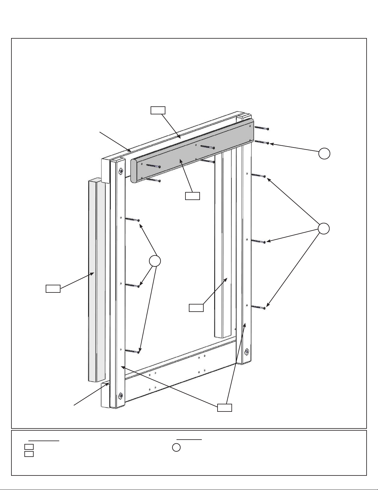
Step 20: Upper Crowsnest Assembly
Part 2
D: Attach 1 (203) Crowsnest Short ush to the top of (200) Crowsnest Top using 6 (S11) #8 x 2” Wood Screws
as shown in g. 20.2.
E: Attach 1 (204) Crowsnest Spacer ush to the outside of each (201) Upright Crowsnest using 3 (S11) #8 x 2”
Wood Screws per board as shown in g. 20.2.
200
Fig. 20.2
Flush
S11
x 6
203
204
Flush
S11
S11
204
201
Wood Parts
203
1 x Crowsnest Short 5/4 x 4 x 25-1/2”
204
2 x Crowsnest Spacer 1-1/4 x 2 x 27-1/2”
Hardware
S11
12 x #8 x 2” Wood Screw
Page 58
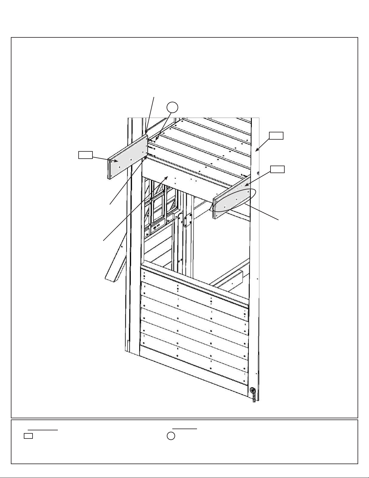
Step 21: Crowsnest Assembly
Part 1
A: Attach 1 (210) Crowsnest Bottom Side ush to the inside edge of the panel posts on (040) Slide End
Panel and tight to the top of the oor support on (040) Slide End Panel using 3 (S11) #8 x 2” Wood Screws
per side. Notice pilot holes towards bottom of boards. (g. 21.1)
Flush
Fig. 21.1
210
S11
x 3 per
board
040
210
Flush
Floor
Support
Notice holes
at bottom of
boards
Wood Parts
210
2 x Crowsnest Bottom Side 3/4 x 5-1/4 x 14-3/4”
Hardware
S11
6 x #8 x 2” Wood Screw
Page 59
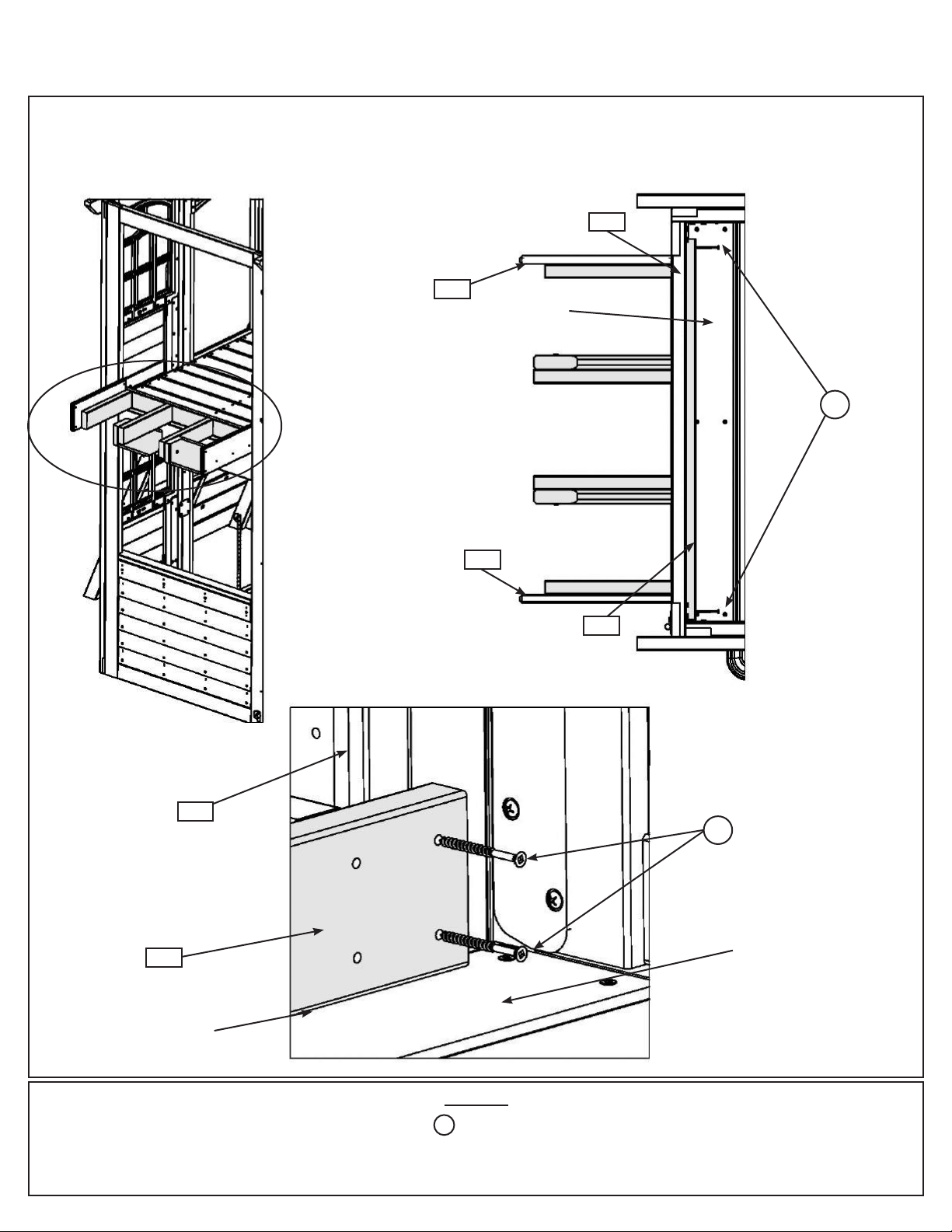
Step 21: Crowsnest Assembly
Part 2
B: Place the Lower Crowsnest Assembly from Step 19 centred in the opening of (040) Slide End Panel, in
between (210) Crowsnest Bottom Sides, tight to the top of the oor boards then attach with 2 (S11) #8 x 2” Wood
Screws per side. (g. 21.2, 21.3 and 21.4)
Fig. 21.2
210
210
Fig. 21.3
Top View
Floor
Boards
040
S11
x 4
192
Fig. 21.4
Inside View
040
S11
x 2 per
side
Floor
192
Tight
Hardware
S11
4 x #8 x 2” Wood Screw
Boards
Page 60
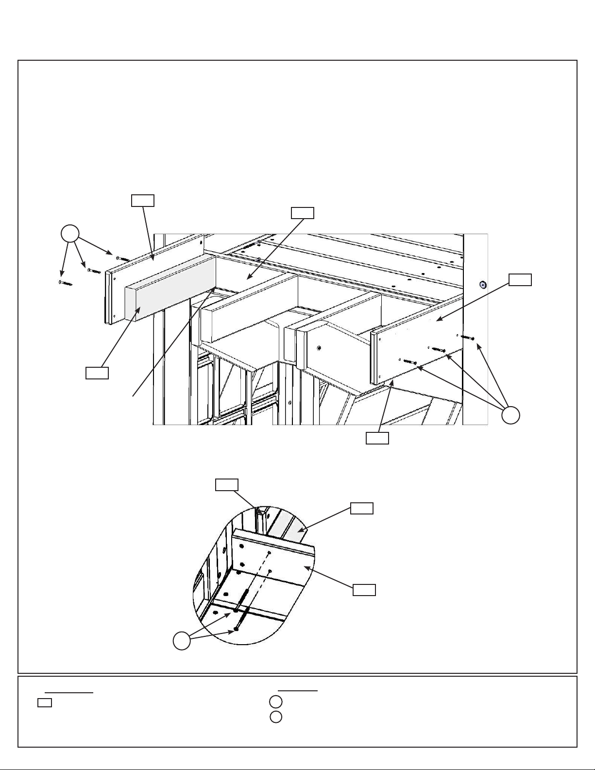
Step 21: Crowsnest Assembly
Part 3
C: Attach 1 (211) Short Crowsnest Joist tight to (192) Crowsnest Back and ush to the bottom of each (210)
Crowsnest Bottom Side using 3 (S20) #8 x 1-3/8” Wood Screws per board as shown in g. 21.5. Screws to be
installed from outside the assembly.
D: From inside the assemby attach (192) Crowsnest Back to each (211) Short Crowsnest Joist with 2 (S3) #8 x
2-1/2” Wood Screws per joist. (g. 21.6)
S20
211
210
Flush
and Tight
Fig. 21.5
192
210
S20
211
(hidden)
210
211
Fig. 21.6
Inside View
192
S3
x 2 per
joist
Wood Parts
211
2 x Short Crowsnest Joist 2 x 4 x 12-1/2”
Hardware
S20
6 x #8 x 1-3/8” Wood Screw
4 x #8 x 2-1/2” Wood Screw
S3
Page 61
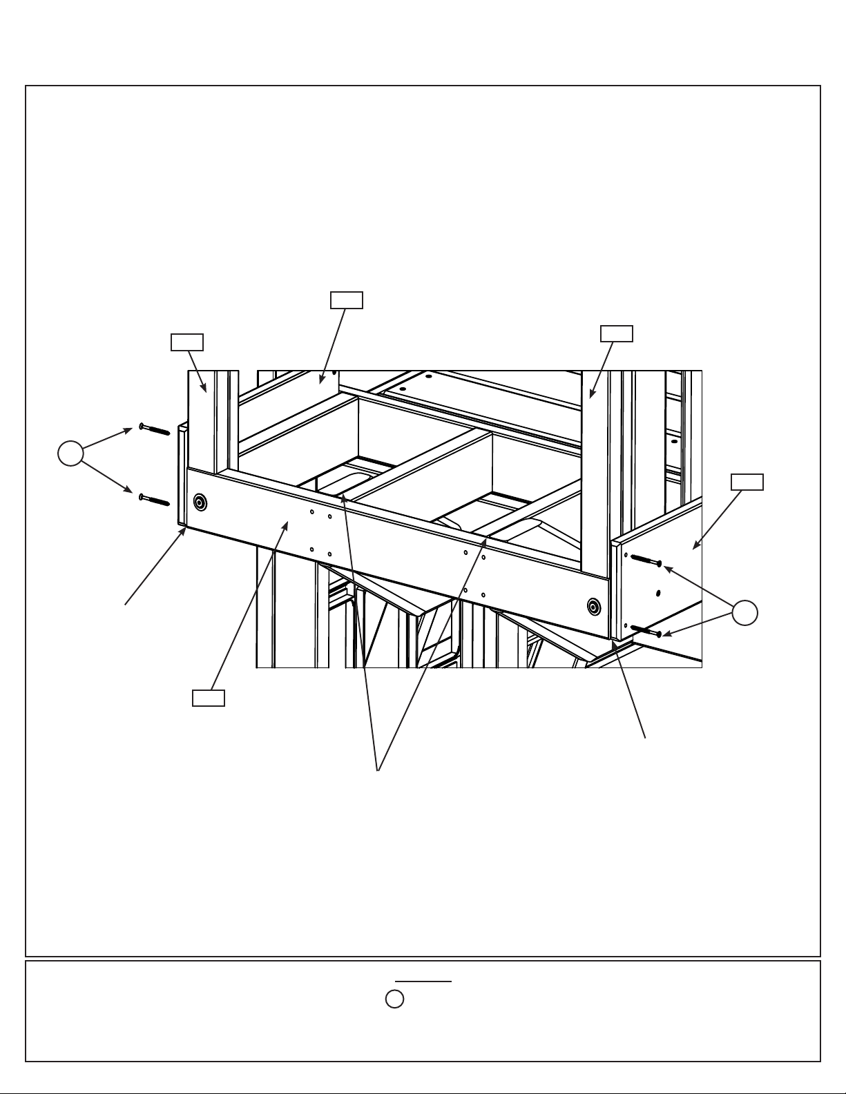
Step 21: Crowsnest Assembly
Part 4
E: Place Upper Crowsnest Assembly from Step 20 in between (210) Crowsnest Bottom Sides so (202)
Crowsnest Front is ush to the bottom and front of each (210) Crowsnest Bottom Side and to the tops of (190)
Crowsnest Gussets and (191) Crowsnest Joists. Attach with 2 (S11) #8 x 2” Wood Screws per board. Screws go
into (202) Crowsnest Front and (204) Crowsnest Spacer. (g. 21.7)
Fig. 21.7
210
S11
Flush
204
204
210
S11
202
Flush
Flush
Hardware
S11
4 x #8 x 2” Wood Screw
Page 62
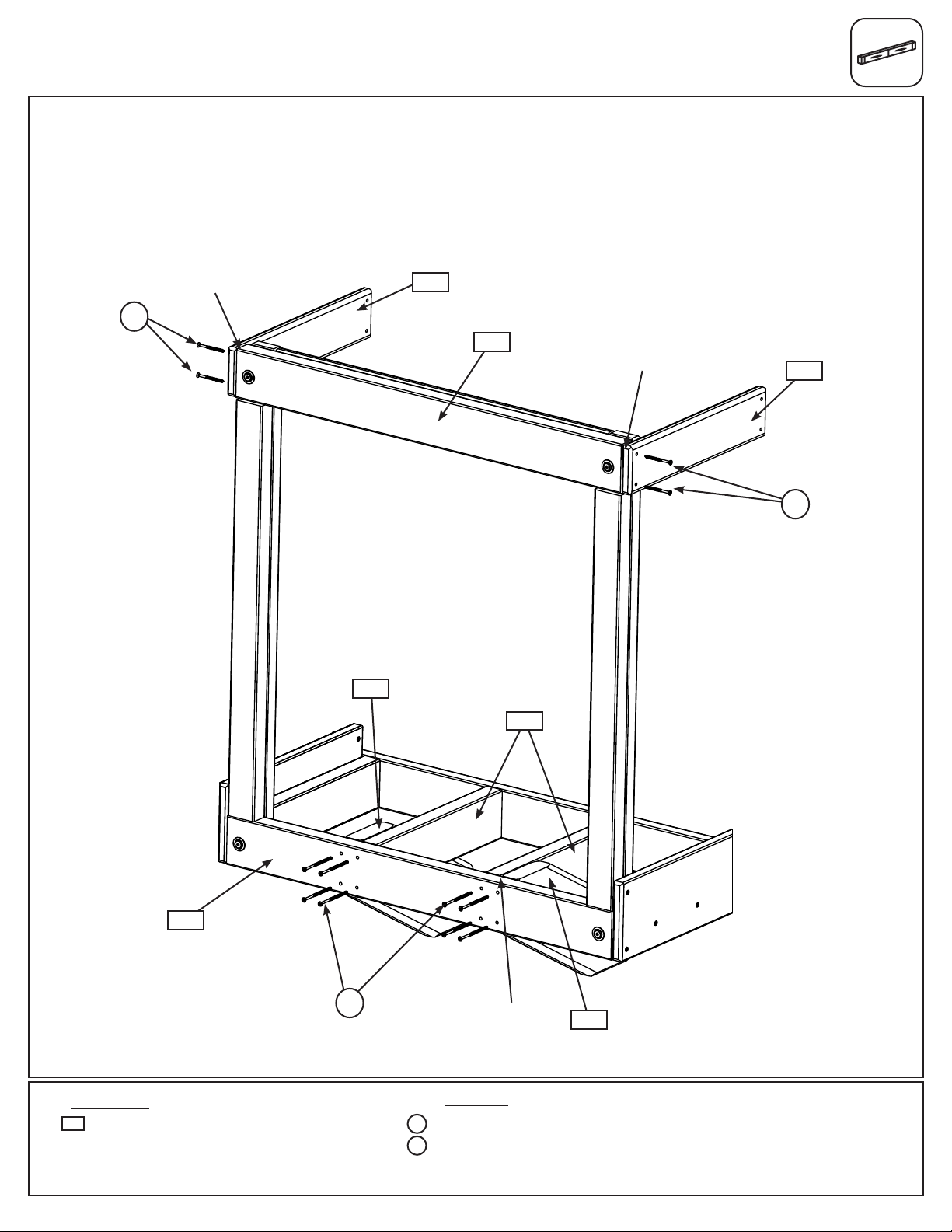
Step 21: Crowsnest Assembly
Part 5
F: Attach (202) Crowsnest Front to each (190) Crowsnest Gusset and each (191) Crowsnest Joist with 8 (S4) #8
x 3” Wood Screws. (g. 21.8)
G: Place 1 (212) Crowsnest Side ush to the top and front of (200) Crowsnest Top make sure each board is level
then attach with 2 (S3) #8 x 2-1/2” Wood Screws per board. (g. 21.8)
S3
Flush and
level
190
212
200
191
Fig. 21.8
Flush and
level
212
S3
202
S4
x 8
Wood Parts
212
2 x Crowsnest Side 3/4 x 3-1/4 x 14-3/4”
8 x #8 x 3” Wood Screw
4 x #8 x 2-1/2” Wood Screw
Hardware
S4
S3
Flush
190
Page 63
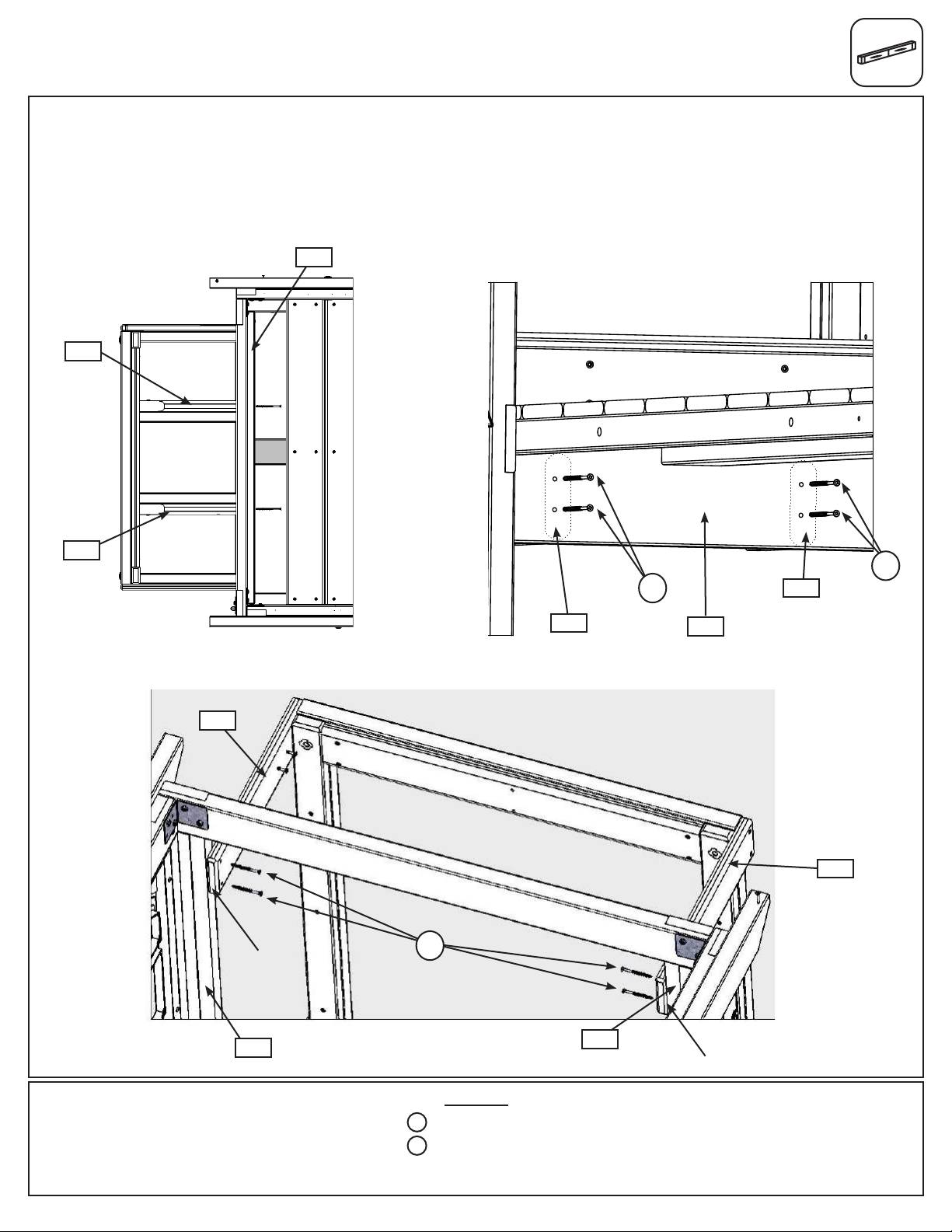
Step 21: Crowsnest Assembly
Part 6
H: From inside the assembly attach (040) Slide End Panel to each (190) Crowsnest Gusset with 2 (S4) #8 x 3”
Wood Screws per gusset. (g. 21.9 and 21.10)
I: Double check that each (212) Crowsnest Side is level then attach to (040) Slide End Panel ush to the inside
of the panel post with 2 (S3) #8 x 2-1/2” Wood Screws per board. (g. 21.11)
Fig. 21.9
Top View
190
190
Floor Board
removed for clarity
040
190
Fig. 21.10
Inside View
S4
040
S4
190
Fig. 21.11
212
Flush
040
S3
Hardware
S4
4 x #8 x 3” Wood Screw
S3
4 x #8 x 2-1/2” Wood Screw
212
040
Flush
Page 64
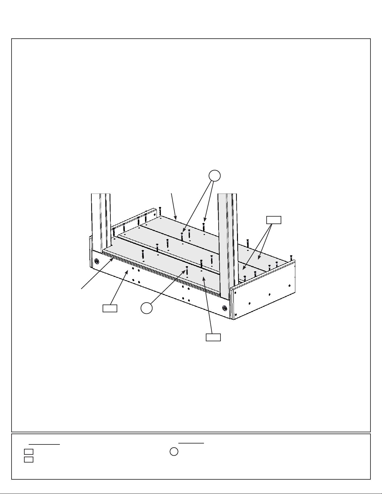
Step 22: Crowsnest Floor Assembly
A: Lay down (220) Crowsnest Gap Board ush to front of (202) Crowsnest Front and (221) Crowsnest Floor
ush to back of (192) Crowsnest Back. In between the gap and oor boards place another (221) Crowsnest
Floor. (g. 22.1)
B: Attach the (221) Crowsnest Floor Boards with 8 (S20) #8 x 1-3/8” Wood Screws per board and the (220)
Crowsnest Gap Board with 6 (S20) #8 x 1-3/8” Wood Screws. (g. 22.1)
Fig. 22.1
Flush
202
S20
x 6
Flush
S20
220
x 8 per
oor board
221
Wood Parts
220
1 x Crowsnest Gap Board 1 x 6 x 29-3/8”
221
2 x Crowsnest Floor 1 x 6 x 29-3/8”
22 x #8 x 1-3/8” Wood Screw
Hardware
S20
Page 65
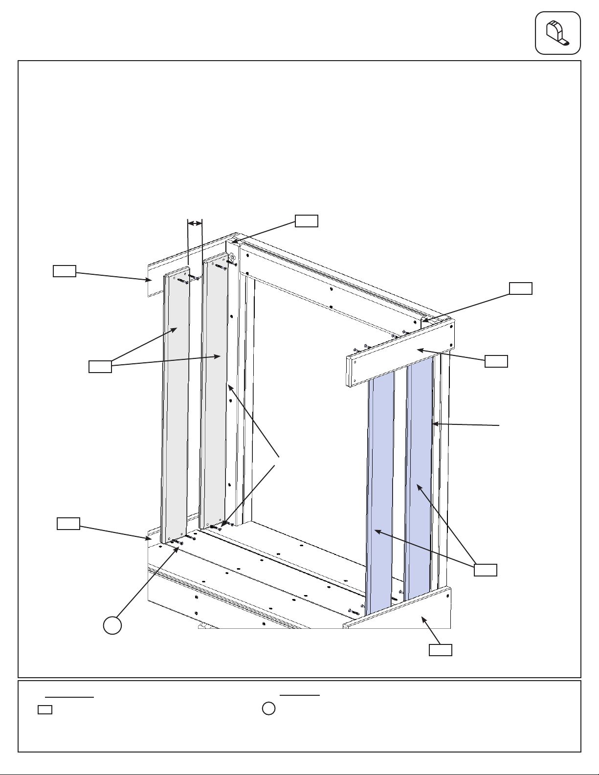
Step 23: Crowsnest Wall Assembly
A: Tight to each (201) Upright Crowsnest and tight to the oor and gap boards attach 1 (230) Cedar Wall to each
(210) Crowsnest Bottom Side and (212) Crowsnest Side with 4 (S33) #8 x 1” Wood Screws per board. (g. 23.1)
B: Measure 2-1/4” from each (230) Cedar Wall then attach another (230) Cedar Wall per side, tight to the oor
and gap boards using 4 (S33) #8 x 1” Wood Screws per board. (g. 23.1)
C: If you purchased a Brockwell refer to Step 46, once completed return to Step 34 and continue.
212
Bevelled edges
facing out.
230
2-1/4”
201
Fig. 23.1
201
212
Tight
Tight
210
230
S33
x 4 per
board
210
Wood Parts
230
4 x Cedar Wall 1 x 4 x 29”
16 x #8 x 1” Wood Screw
Hardware
S33
Page 66
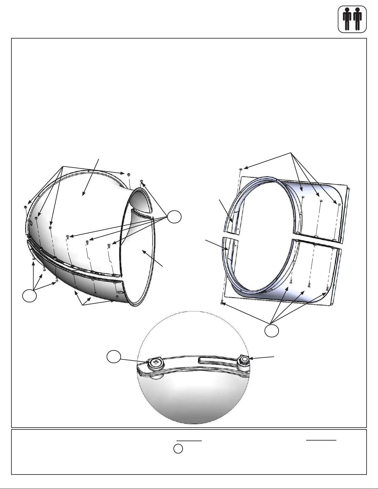
Step 24: Slide Section Assemblies
Part 1
(Preston/ Twin
MountainLodge)
Note: When installing Pan Bolts make sure to look at holes so bolts go through the side with the
round recess and the lock nuts go through the side with the hexagonal recess. (g. 24.3)
A: Fit 2 TNR2 Slide Elbows together and attach with 8 (PB1) 1/4 x 3/4” Pan Bolts (with lock nut) as shown in
g. 24.1. It is very important to attach bolts as indicated.
B: Repeat Step A 3 more times to create 4 Elbow Sections in total.
C: Attach TNR2 Slide RT Flange and TNR2 Slide LT Flange together using 4 (PB1) 1/4 x 3/4” Pan Bolts (with
lock nut) as shown in g. 24.2. This creates the Flange Assembly.
Fig. 24.1
PB1
Lock
Nut
Lock
Nut
TNR2
Slide
Elbow
PB1
TNR2
Slide
Elbow
Fig. 24.2
TNR2
Slide LT
Flange
TNR2
Slide RT
Flange
Flange
Assembly
Lock
Nut
PB1
Fig. 24.3
PB1
Use a 7/16” open end
wrench for nuts
Hardware
PB1
36 x 1/4 x 3/4” Pan Bolt
(1/4”locknut)
Lock
Nut
Other Parts
1 x TNR2 Slide LT Flange
1 x TNR2 Slide RT Flange
8 x TNR2 Slide Elbow
Page 67
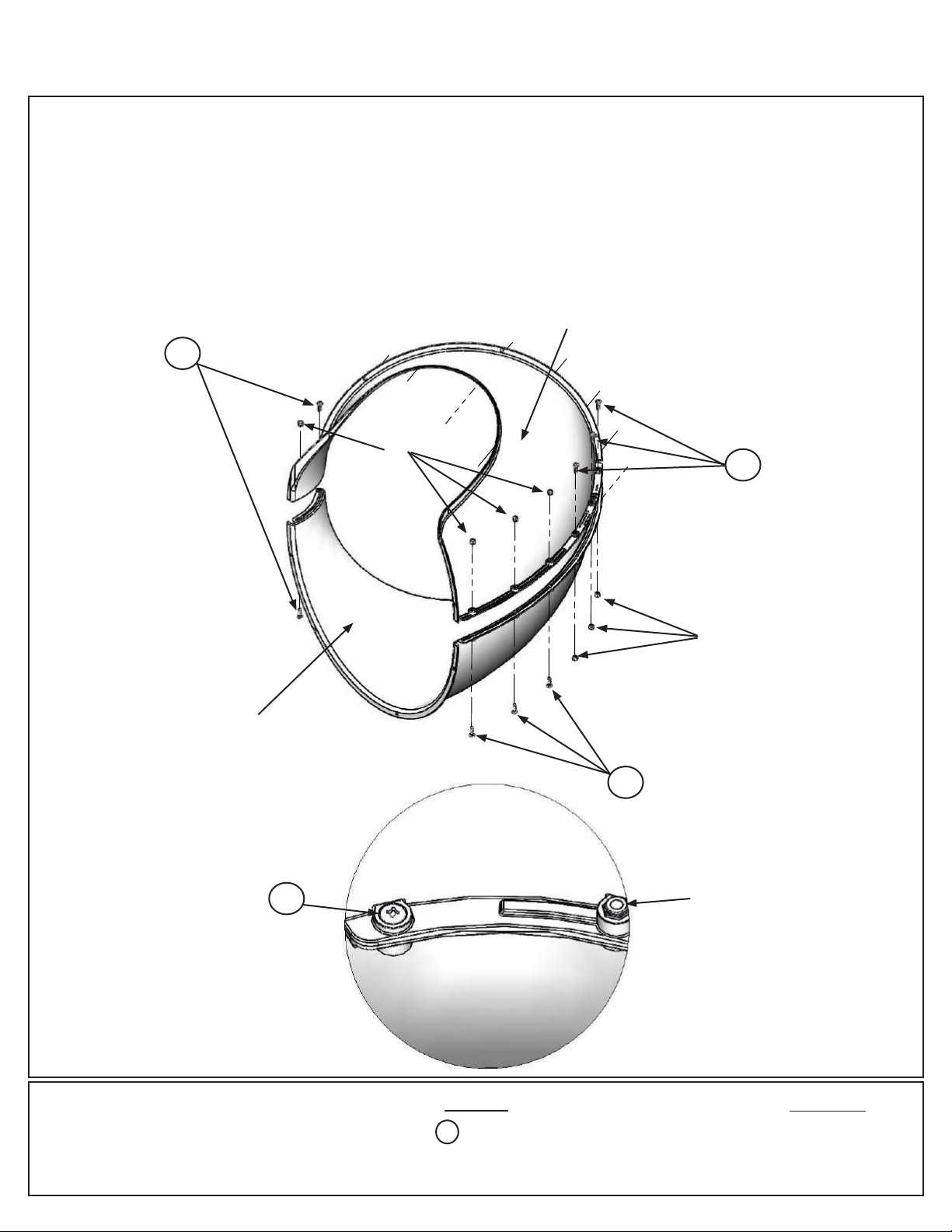
Step 24: Slide Section Assemblies
Part 2
Note: When installing Pan Bolts make sure to look at holes so bolts go through the side with the
round recess and the lock nuts go through the side with the hexagonal recess. (g. 24.3)
D: Attach TNR2 Slide Exit Top and the remaining TNR2 Slide Elbow together using 8 (PB1) 1/4 x 3/4” Pan
Bolts (with lock nut) as shown in g. 24.4. It is very important to attach bolts as indicated. This creates the
Exit Elbow Assembly.
TNR2
Fig. 24.4
PB1
Lock
Nut
Slide Exit
Top
PB1
TNR2
Slide
Elbow
Fig. 24.3
PB1
Lock
Nut
PB1
Lock
Nut
Hardware
PB1
8 x 1/4 x 3/4” Pan Bolt
(1/4”locknut)
Other Parts
1 x TNR2 Slide Exit Top
1 x TNR2 Slide Elbow
Page 68
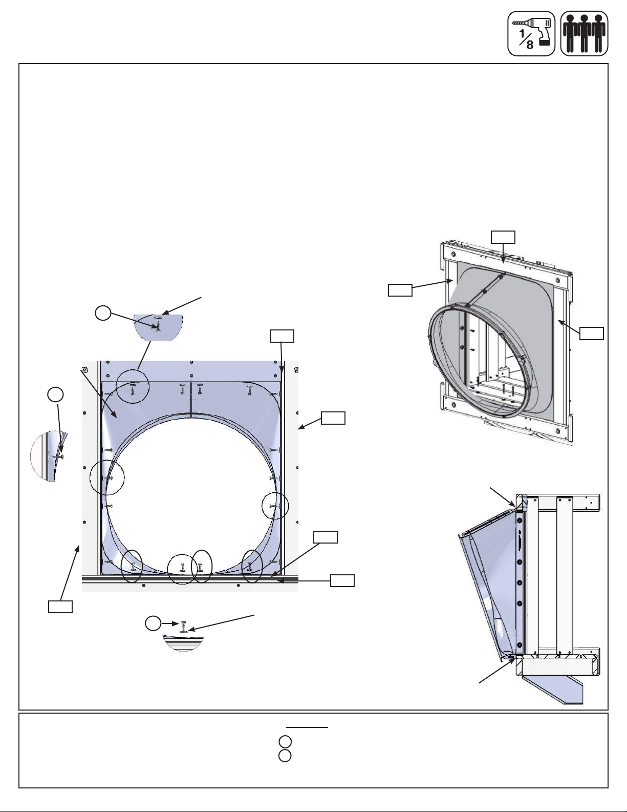
Step 25: Attach Flange Assembly to Fort
A: With a helper place the Flange Assembly ush to the Crowsnest on the fort as shown in g. 25.1 and 25.5,
then pre-drill 1/8” pilot holes in the bottom 4 mounting locations on (220) Crowsnest Gap Board (approximate
spots where circles are on gure), making sure the pre-drilled holes are a minimum of 1” deep.
B: Attach Flange Assembly to the Crowsnest through (220) Crowsnest Gap Board and into (202) Crowsnest
Front using 4 (S7) #12 x 2” Pan Screws (with #12 Screw Bezel) in the pre-drilled holes. (g. 25.1 and 25.2)
Make sure the at surfaces of the Flange Assembly are ush to the Crowsnest as shown in g. 25.5.
C: Attach the Flange Assembly ush to (200) Crowsnest Top using 4 (S6) #12 x 1” Pan Screws (with #12
Screw Bezel) as shown in g. 25.1 and 25.3 and to both (204) Crowsnest Spacers using 5 (S6) #12 x 1” Pan
Screw per board. (g. 25.1 and 25.4)
Top
Fig. 25.3
Fig. 25.1
S6
#12 Screw
Bezel
Fig. 25.6
204
(hidden)
200
200
204
Flange
Assembly
S6
Sides
Fig. 25.4
204
(hidden)
Inside View
S7
#12 Screw
Bezel
204
(hidden)
220
202
Outside View
Topofslideush
to(200)Crowsnest
Top
Fig. 25.5
Fig. 25.2
Bottom
Bottom of
slideush
with deck
Hardware
S6
14 x #12 x 1” Pan Screw
S7
4 x #12 x 2” Pan Screw
8 x #12 Screw Bezel
Page 69
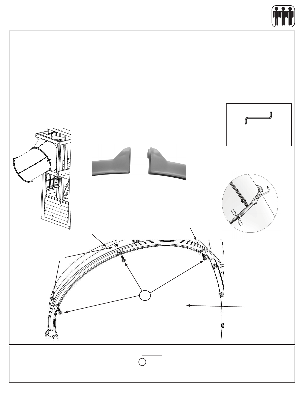
Step 26: Attach Elbow Assembly to Flange Assembly
Part 1
Note: When installing Pan Bolts make sure to look at holes so bolts go through the side with the
round recess and the lock nuts go through the side with the hexagonal recess. Keep all bolts loose
until further step.
A: Fit one of the Elbow Assemblies to the Flange Assembly by lining up the arrows on each assembly. (g.
26.2 and 26.3)
B: Attach 1 TNR2 Slide Clamp Ring to the top of the joined Assemblies using 3 (PB1) 1/4 x 3/4” Pan Bolts
(with lock nut), making sure to match the arrows up with the end of the clamp ring (where a seam will be) as
shown in g. 26.2 and 26.3.
Use Quadrex Driver as a guide pin for each hole before inserting bolt. (g. 26.3)
Fig. 26.1
Fig. 26.4
Quadrex Driver
Use special driver provided
in locations where the curve
of the elbow are dicult to
reach with a standard driver.
Lock
Nut
Flange
Assembly
Do not install bolt
in Clamp Ring ends
until Step 26D
Fig. 26.2
Top Slide Bolt Holes
PB1
Fig. 26.3
Lock
Nut
Align each elbow using the
molded arrows with the seam
of the clamp ring.
Elbow
Assembly
Hardware
PB1
3 x 1/4 x 3/4” Pan Bolt
(1/4”locknut)
Other Parts
1 x Quadrex Driver
1 x TNR2 Slide Clamp Ring
Page 70
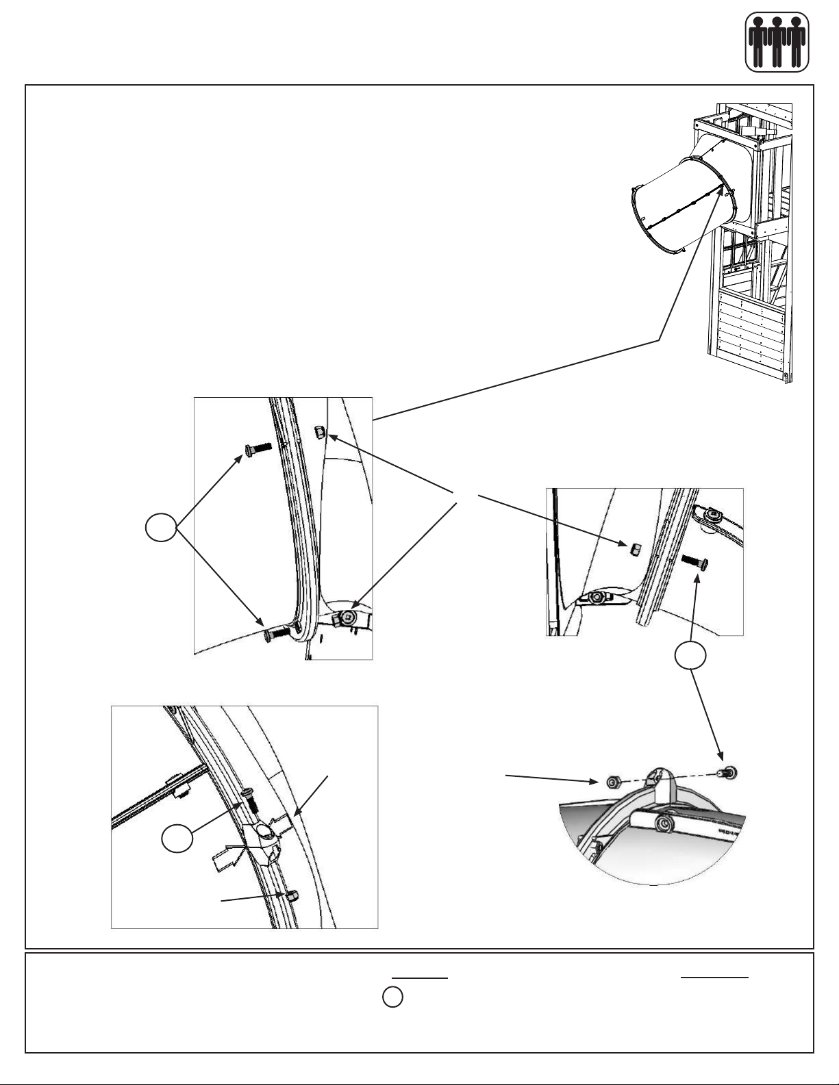
Step 26: Attach Elbow Assembly to Flange Assembly
Part 2
Note: When installing Pan Bolts make sure to look at holes so bolts
go through the side with the round recess and the lock nuts go
through the side with the hexagonal recess. Keep all bolts loose until
further step.
C: Attach 1 TNR2 Slide Clamp Ring to the bottom of the joined Assemblies
using 2 (PB1) 1/4 x 3/4” Pan Bolts (with lock nut) on one side and 1 (PB1)
1/4 x 3/4” Pan Bolt (with lock nut) in the other side, making sure to match
the arrows up with the end of the clamp ring (where a seam will be) as
shown in g. 26.5, 26.6 and 26.7.
D: Connect the 2 TNR2 Slide Clamp Rings together in 2 spots using 1
(PB1) 1/4 x 3/4” Pan Bolt (with lock nut) per hole. Make sure seams and
arrows line up and then tighten all bolts. (g. 26.8 and 26.9).
Fig. 26.6
Fig. 26.5
Fig. 26.8
PB1
PB1
Lock
Nut
Make sure
arrows are
aligned
Lock
Nut
Bottom Slide Bolt Holes
Lock
Nut
After the clamp rings
are attached to the
elbows, fasten them
end to end with two
pan bolts and lock nuts
Fig. 26.7
Fig. 26.9
(Sidenotshown)
PB1
Hardware
PB1
5 x 1/4 x 3/4” Pan Bolt
(1/4”locknut)
Other Parts
1 x TNR2 Slide Clamp Ring
Page 71
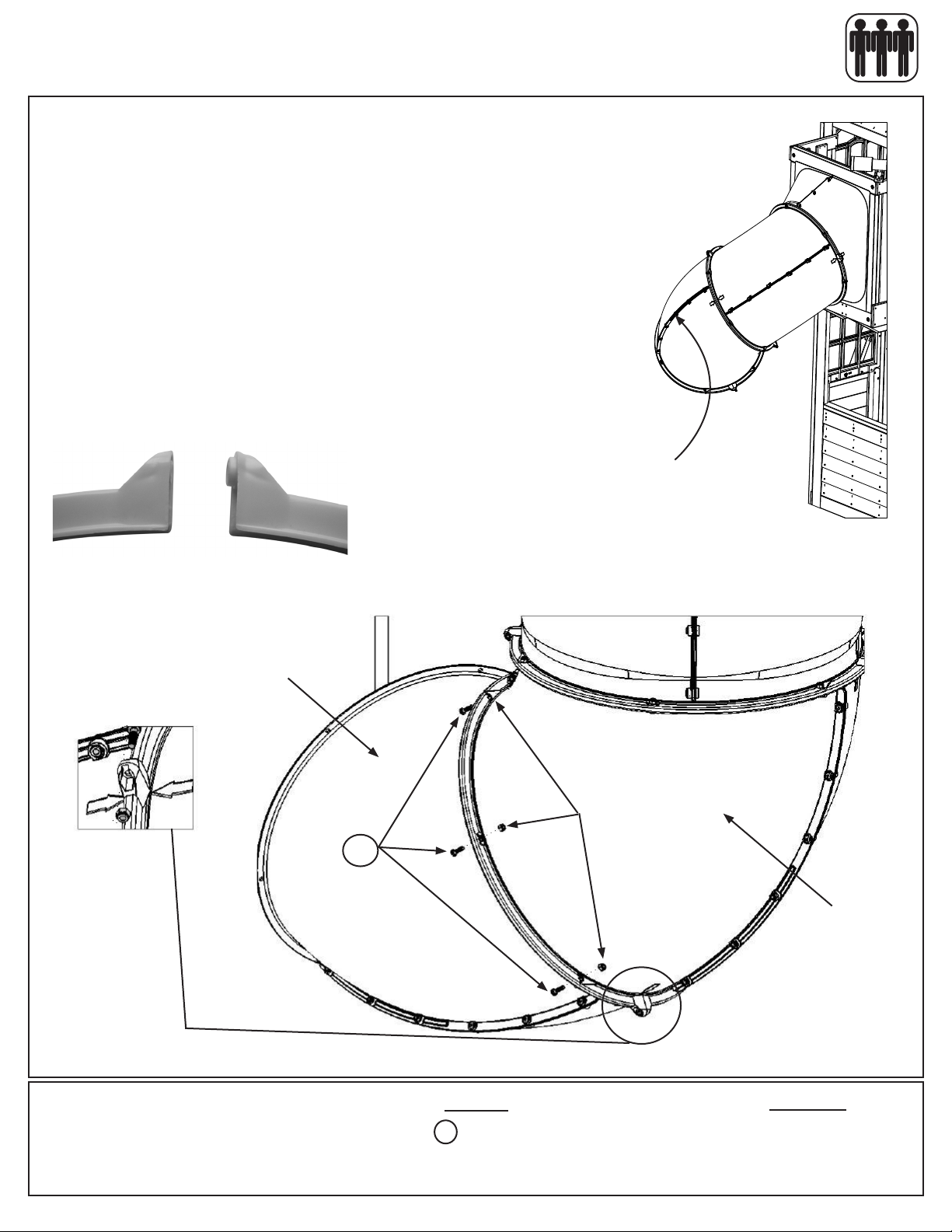
Step 27: Attach Elbow Assembly to Elbow Assembly
Part 1
Note: When installing Pan Bolts make sure to look at holes so bolts go
through the side with the round recess and the lock nuts go through
the side with the hexagonal recess. Keep all bolts loose until further
step.
A: Fit a second Elbow Assembly to the rst Elbow Assembly by lining up the
arrows on each assembly. Notice the elbow orientation. (g. 27.1)
B: Attach 1 TNR2 Slide Clamp Ring to the top of the joined Assemblies
using 3 (PB1) 1/4 x 3/4” Pan Bolts (with lock nut), making sure to match the
arrows up with the end of the clamp ring (where a seam will be) as shown in
g. 27.2 and 27.3.
Use Quadrex Driver as a guide pin for each hole before inserting bolt.
Notice elbow
orientation
Fig. 27.1
Do not install bolt
in Clamp Ring ends
until Step 27D
Fig. 27.3
Make sure
arrows are
aligned
Fig. 27.2
Top Slide Bolt Holes
Elbow
Assembly
Lock
Nut
PB1
Elbow
Assembly
Hardware
PB1
3 x 1/4 x 3/4” Pan Bolt
(1/4”locknut)
Other Parts
1 x TNR2 Slide Clamp Ring
Page 72
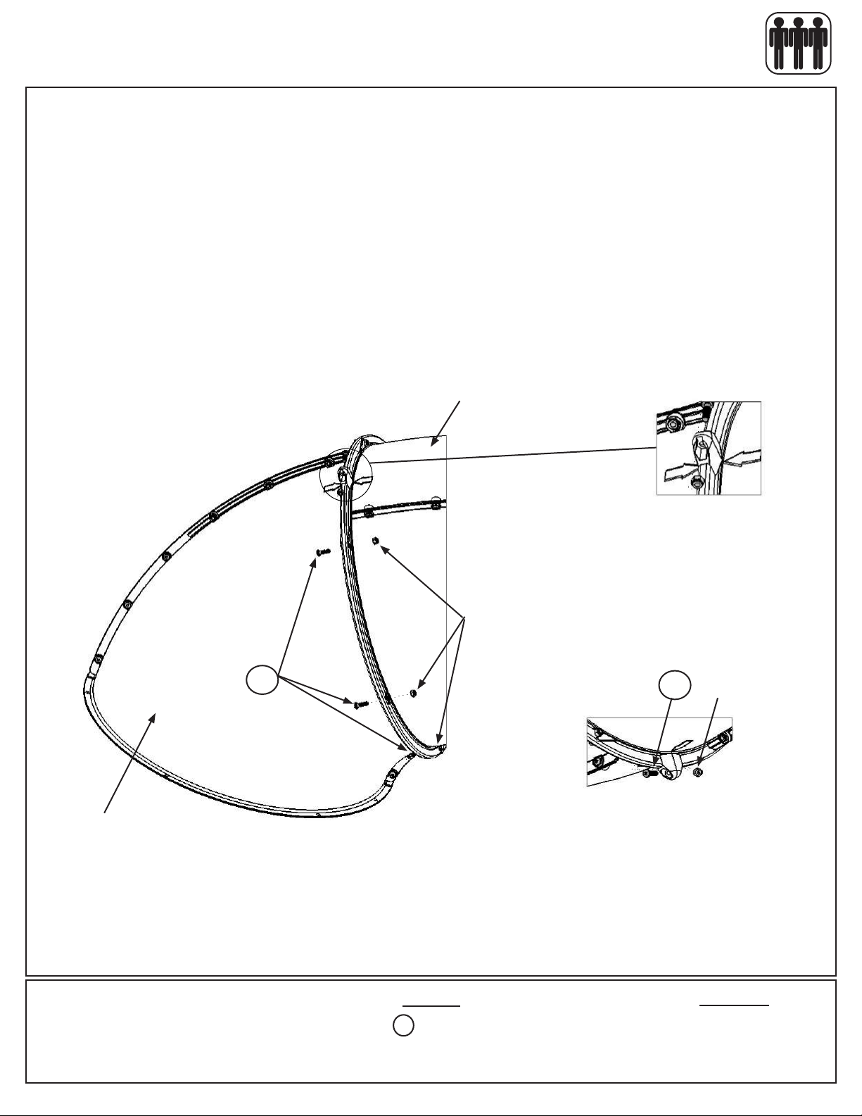
Step 27: Attach Elbow Assembly to Elbow Assembly
Part 2
Note: When installing Pan Bolts make sure to look at holes so bolts go through the side with the
round recess and the lock nuts go through the side with the hexagonal recess. Keep all bolts loose
until further step.
C: Attach 1 TNR2 Slide Clamp Ring to the bottom of the joined Assemblies using 3 (PB1) 1/4 x 3/4” Pan Bolts
(with lock nut), making sure to match the arrows up with the end of the clamp ring (where a seam will be) as
shown in g. 27.3 and 27.4.
D: Connect the 2 TNR2 Slide Clamp Rings together in 2 spots using 1 (PB1) 1/4 x 3/4” Pan Bolt (with lock
nut) per hole. Make sure seams and arrows line up and then tighten all bolts. (g. 27.3 and 27.5).
Fig. 27.4
Bottom Slide Bolt Holes
PB1
Elbow
Assembly
Lock
Nut
Fig. 27.5
Fig. 27.3
Make sure arrows
are aligned
PB1
Lock
Nut
Elbow
Assembly
Hardware
PB1
5 x 1/4 x 3/4” Pan Bolt
(1/4”locknut)
After the clamp rings
are attached to the
elbows, fasten them
end to end with two
pan bolts and lock nuts
Other Parts
1 x TNR2 Slide Clamp Ring
Page 73
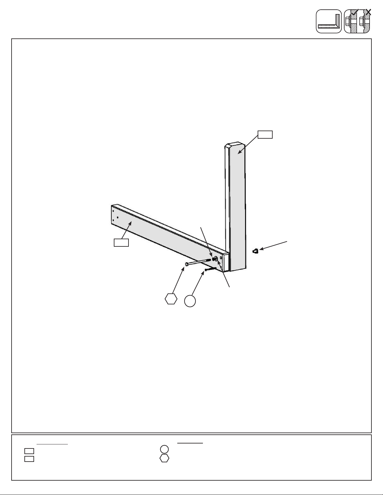
Step 28: TNR Brace Assembly
A: Attach (281) TNR Upright to (280) TNR Ground Brace with 1 (H8) 1/4 x 4-1/4” Hex Bolt (with lock
washer, at washer and t-nut) in the top hole. Make sure both boards are square then attach with 1 (S11)
#8 x 2” Wood Screw. (g. 28.1)
281
Fig. 28.1
280
H8
1/4” Lock
Washer
S11
1/4”
T-Nut
1/4” Flat
Washer
Wood Parts
280
1 x TNR Ground Brace 1-1/4 x 3 x 32-1/4”
281
1 x TNR Upright 1-1/4 x 3 x 20-1/4”
1 x #8 x 2” Wood Screw
1x 1/4x4-1/4”HexBolt(1/4”lockwasher,1/4”atwasher,1/4”t-nut)
Hardware
S11
H8
Page 74
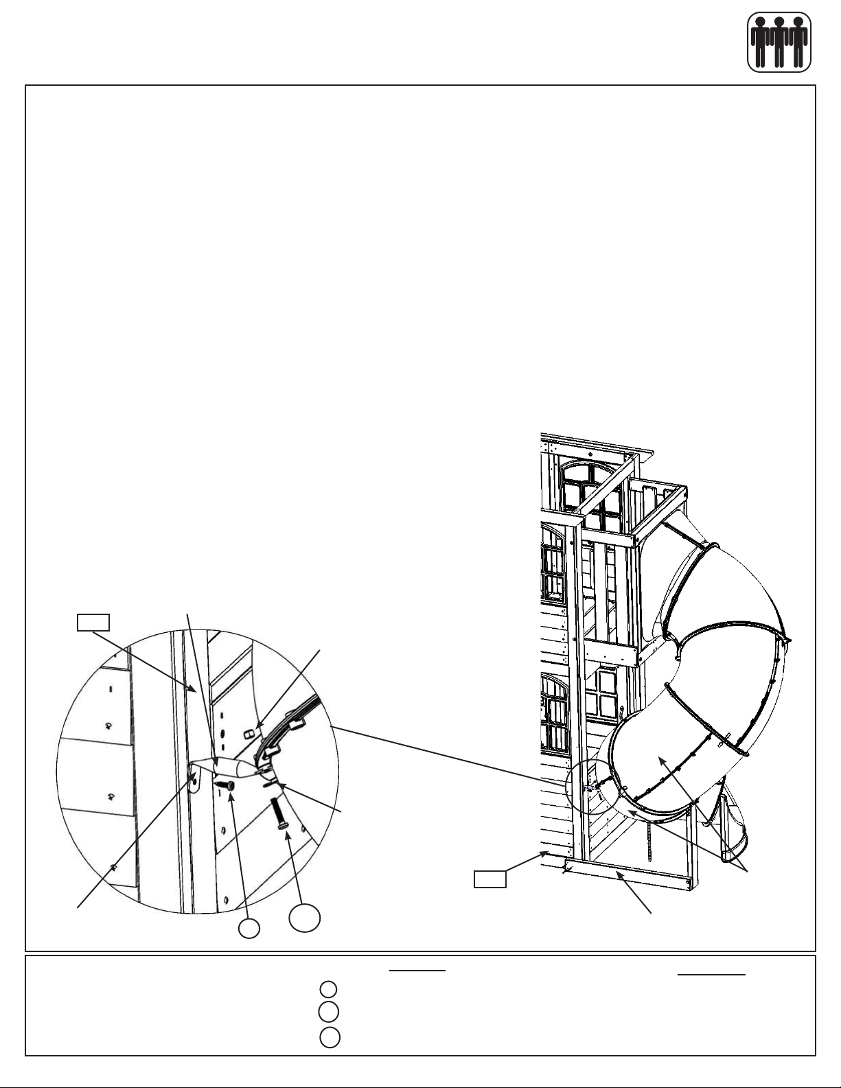
Step 29: Attach Elbow Assemblies and TNR2 Slide
Support
Note: When installing Pan Bolts make sure to look at holes so bolts go through the side with the round
recess and the lock nuts go through the side with the hexagonal recess. Keep all bolts loose until
further step.
A: Attach the two remaining Elbow Assemblies as instructed in Steps 26 and 27.
B: Place TNR Brace Assembly against (041) Narrow Back Panel so it sits under the slide. It is not attached yet.
(g. 29.1)
C: On the fourth attached Elbow Assembly remove the pan bolt and nut which is facing the fort (installed in Step
24). (g. 29.1) The bolt will no longer be needed, but keep the lock nut.
D: Loosely attach TNR3 Tube Support (at the slightly bent end) to the Clamp Ring using 1 (PB6) 1/4 x 1” Pan
Bolt (with at washer and the previously removed lock nut). (g. 29.2)
E: Rotate TNR3 Tube Support and attach to (040) Slide End Panel using 1 (S6) #12 x 1” Pan Screw as shown
in g. 29.2.
F: Fully tighten screw and bolt.
Fig. 29.2
TNR 3 Tube
Support
040
Note: Flat
end down
S6
Remove PB1 (1/4 x 3/4”
PanBolt)rsttheninstall
PB6 (1/4 x 1” Pan Bolt
withatwasher)
Lock
Nut
Flat
Washer
PB6
041
TNR Brace
Assembly
Fig. 29.1
Attach 2
remaining
Elbow
Assemblies
Hardware
S6
1 x #12 x 1” Pan Screw
1 x 1/4 x 1” Pan Bolt
PB6
(1/4”atwasher&1/4”locknut-previouslyremoved)
PB1
16 x 1/4 x 3/4” Pan Bolt
(1/4”locknut)
Other Parts
1 x TNR3 Tube Support
4 x TNR2 Slide Clamp Ring
Page 75
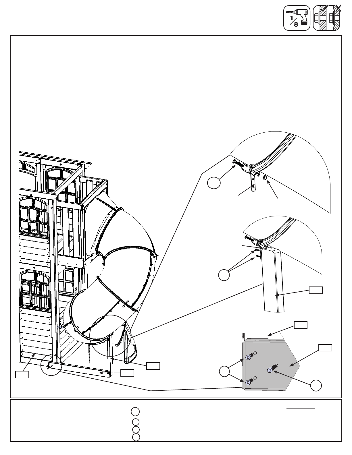
Step 30: Attach TNR Brace Assembly
A: Use (281) TNR Upright as a guide to judge the proper bolt location, remove the bottom pan bolt and nut. The
bolt will no longer be needed, but keep the lock nut. (g. 30.1 and 30.2)
B: Attach the top of the TNR3 Post Mount to TNR2 Slide Clamp Ring using 1 (PB2) 1/4 x 1-1/4” Pan Bolt (with
the previously removed lock nut). (g. 30.2)
C: Insert TNR3 Post Mount on (281) TNR Upright, pre-drill with a 1/8” drill bit then attach with 2 (S6) #12 x 1”
Pan Screws. (g. 30.3)
D: Attach (280) TNR Ground Brace ush to the bottom of (041) Narrow Back Panel with 2 (S11) #8 x 2” Wood
Screws and 1 (S4) #8 x 3” Wood Screw. (g. 30.1 and 30.4)
Fig. 30.1 Fig. 30.2
Remove PB1 (1/4 x 3/4”
PanBolt)rsttheninstall
PB2 (1/4 x 1-1/4” Pan Bolt
with previously removed
locknut)
PB2
TNR3 Post
Mount
Fig. 30.3
TNR3 Post
Mount
S6
Fig. 30.4
Lock
Nut
281
041
280
041
281
280
S11
S4
Hardware
1 x 1/4 x 1-1/4” Pan Bolt
PB2
1-(1/4”locknut-previouslyremoved)
S6
2 x #12 x 1” Pan Screw
S4
1 x #8 x 3” Wood Screw
S11
2 x #8 x 2” Wood Screw
Other Parts
1 x TNR3 Post Mount
Page 76
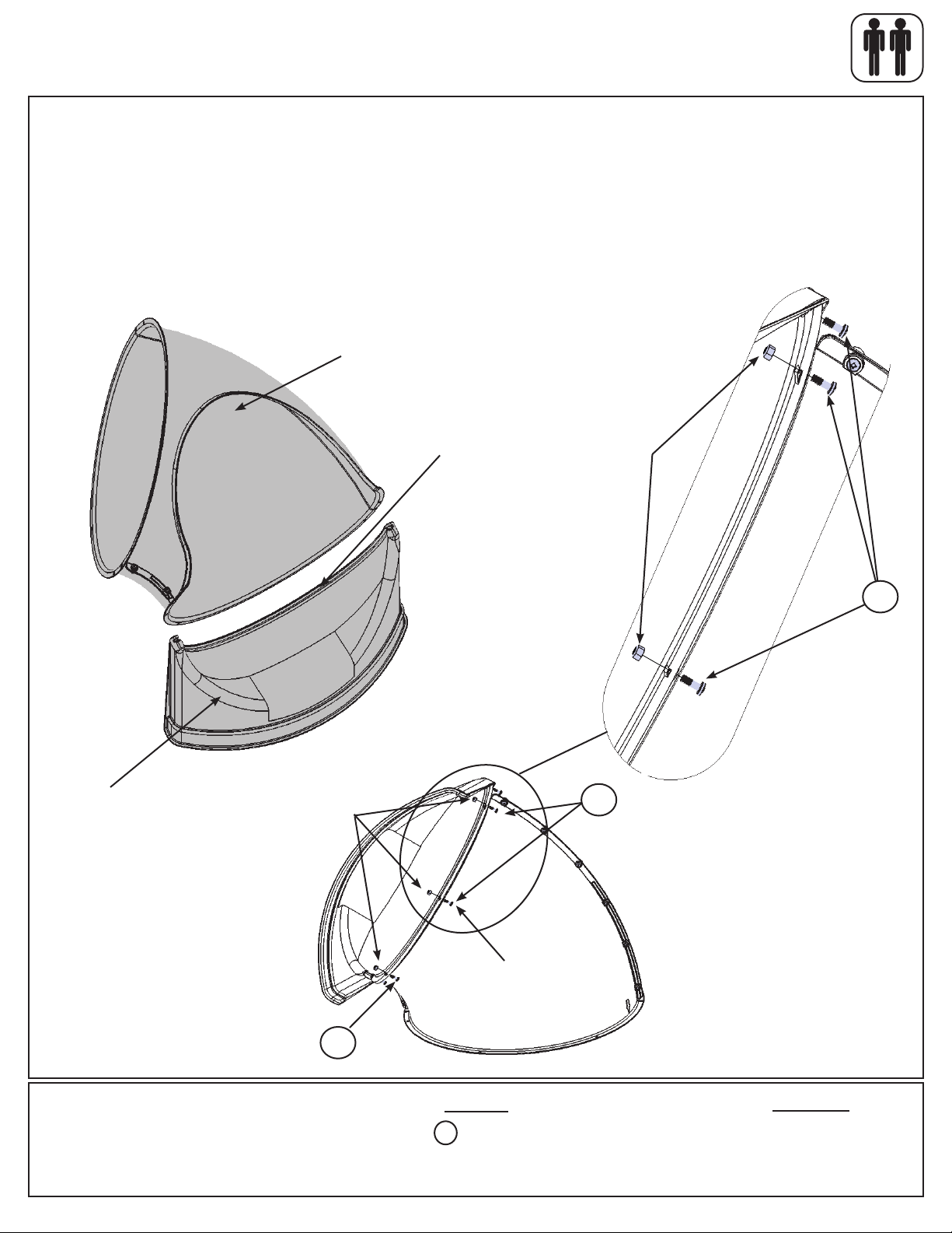
Step 31: Attach TNR3 Slide Exit to Exit Elbow Assembly
A: Insert ange of Exit Elbow Assembly (slide elbow) into the slots on TNR3 Short Exit. (g. 31.1)
B: Rotate Slide Exit and use Quadrex Driver as a guide pin so the holes are aligned and attach with 5 (PB1) 1/4
x 3/4” Pan Bolts (with lock nuts) starting with the bottom middle hole and working up each side. (g. 31.2 and
31.3)
C: At this point make sure all the slide bolts are tight. Use a 7/16” open end wrench to hold nut and then
tighten bolt with Quadrex Driver on Clamp Rings.
Fig. 31.1
TNR3
Short Exit
Exit Elbow
Assembly
Lock
Nut
Slot of TNR3
Short Exit
Fig. 31.3
Lock
Nut
PB1
PB1
Bottom of Slide Views
Fig. 31.2
Start with
this bolt
PB1
Hardware
PB1
5 x 1/4 x 3/4” Pan Bolt
(1/4”locknut)
Other Parts
1 x TNR3 Short Exit
Page 77
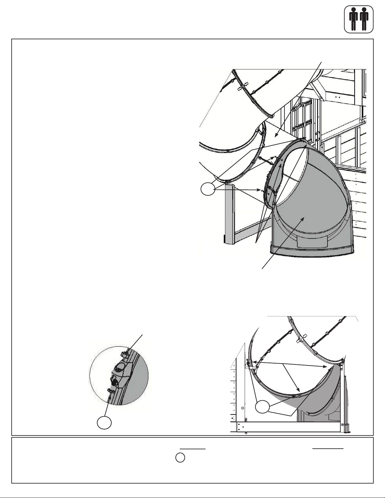
Step 32: Attach Exit End Assembly to Fort
Note: When installing Pan Bolts make sure to
look at holes so bolts go through the side with the
round recess and the lock nuts go through the side
with the hexagonal recess. Keep all bolts loose
until further step.
A: Fit the Exit End Assembly to the last Elbow
Assembly by lining up the arrows on each assembly.
Notice the elbow orientation. (g. 32.1)
B: Place 1 TNR2 Slide Clamp Ring to the top of the
joined Assemblies, rotate counter clockwise 1 hole
location then attach with 3 (PB1) 1/4 x 3/4” Pan Bolts
(with lock nut) as shown in g. 32.1.
Use Quadrex Driver as a guide pin for each hole
before inserting bolt.
C: Attach 1 TNR2 Slide Clamp Ring to the bottom of
the joined Assemblies using 3 (PB1) 1/4 x 3/4” Pan
Bolts (with lock nut) as shown in g. 32.2.
Fig. 32.1
PB1
Top Slide Bolt Holes
Elbow
Assembly
D: Connect the 2 TNR2 Slide Clamp Rings together
in 2 spots using 1 (PB1) 1/4 x 3/4” Pan Bolt (with lock
nut) per hole. Make sure seams and arrows line up and
then tighten all bolts. (g. 32.3).
Lock Nut
Fig. 32.3
After the clamp rings
are attached to the
elbows, fasten them
end to end with two
pan bolts and lock nuts
PB1
Fig. 32.2
Lock
Nut
Exit Elbow
Assembly
Bottom Slide Bolt Holes
Lock Nut
PB1
Make sure arrows
are aligned
Hardware
PB1
8 x 1/4 x 3/4” Pan Bolt
(1/4”locknut)
Other Parts
2 x TNR2 Slide Clamp Ring
Page 78
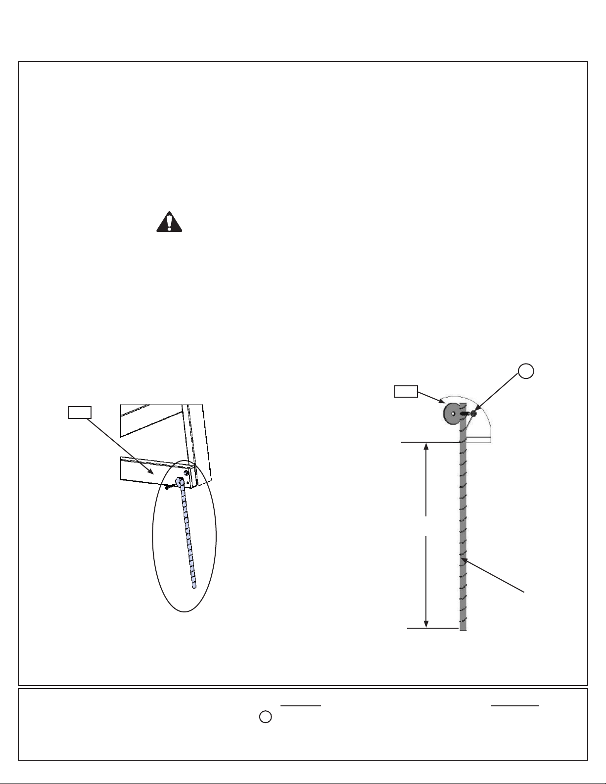
Step 33: Attach Ground Stake to TNR Upright
A: In the spot shown in g. 33.1 drive 1 Rebar Ground Stake 13” into the ground against the (281) TNR
Upright. Be careful not to hit the washer while hammering stake into the ground as this could cause the
washer to break o.
B: Attach the ground stake to (280) Ground Brace just below the bolt head using 1 (S7) #12 x 2” Pan Screw
as shown in g. 33.2.
C: After driving stakes into the ground, check for sharp edges caused by the impact of the hammer. Smooth
any sharp edges from impact area and touch up with outdoor paint.
Warning! To prevent tipping and avoid potential
injury, stakes must be driven 13” into ground.
Digging or driving stakes can be dangerous if you
donotcheckrstforunder-groundwiring,cables
or gas lines.
Fig. 33.1
280
Fig. 33.2
S7
280
13” In Ground
Rebar
Ground
Stake
Hardware
S7
1 x #12 x 2” Pan Screw
Other Parts
1 x Rebar Ground Stake
Page 79
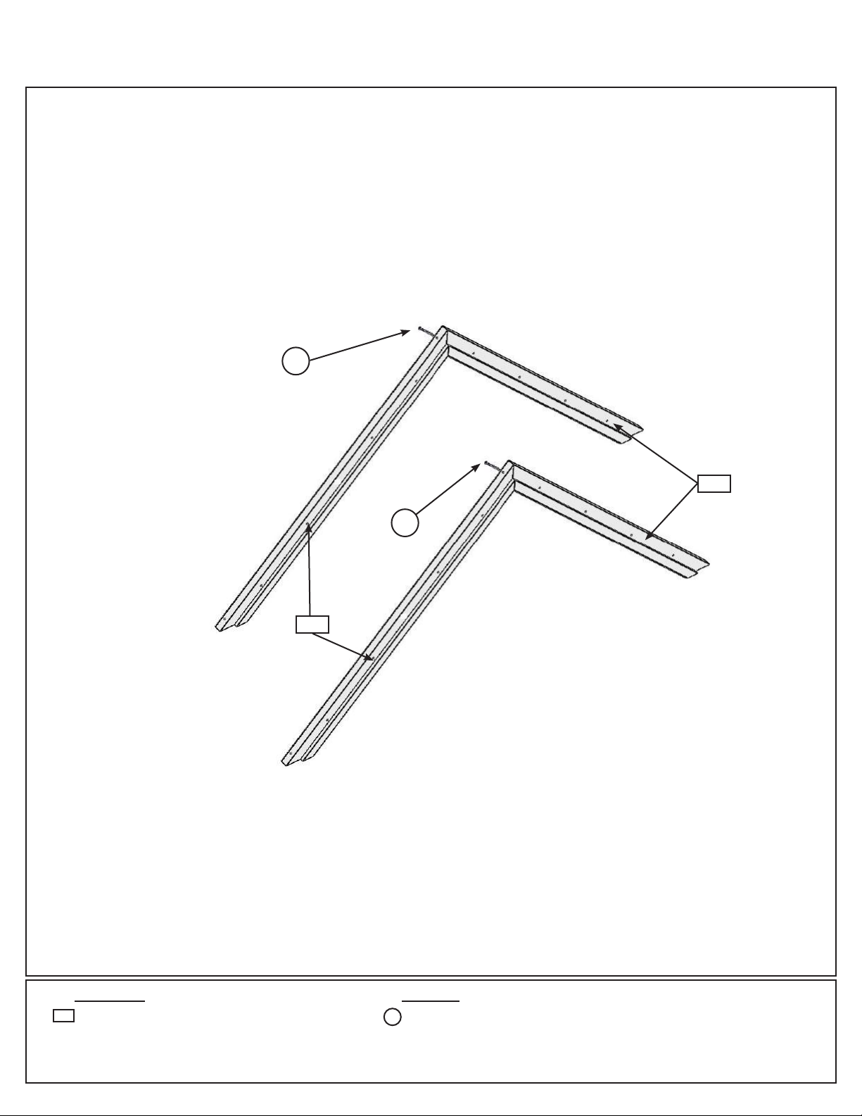
Step 34: Roof Rafter Assembly
A: Attach 1 (340) Roof Rafter to a second (340) Roof Rafter at peak using 1 (S4) #8 x 3” Wood Screw. Repeat
this twice so there are 2 Roof Rafter Assemblies. (g. 34.1)
Fig. 34.1
S4
Roof Rafter
Assembly
340
340
S4
Wood Parts Hardware
340
4 x Roof Rafter 1-1/4 x 3 x 50-15/16”
S4
2 x #8 x 3” Wood Screw
Page 80
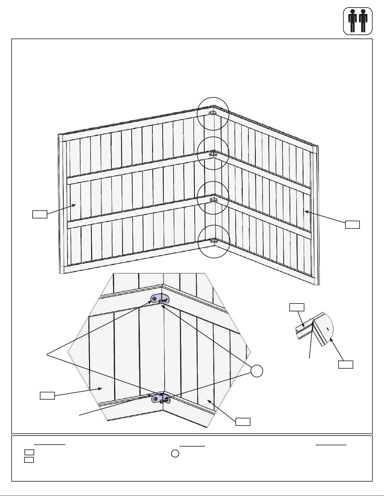
Step 35: Roof Assembly
Part 1
A: Place (350) Roof Panel A against (351) Roof Panel B so the tops form a peak then tight to the inside edge
of the outside slats attach 1 Narrow Angle Bracket per slat with 2 (S0) #8 x 7/8” Truss Screws per bracket. (g.
35.1, 35.2 and 35.3)
B: Attach 2 more Narrow Angle Brackets on the middle slats so they are centred on the slat with 2 (S0) #8 x 7/8”
Truss Screws per bracket. (g. 35.1 and 35.3)
Fig. 35.1
351
Fig. 35.3
Narrow
Angle
Bracket
351
S0
x 2 per
bracket
351
Top Peak
350
Fig. 35.2
350
Flush
Wood Parts
350
1 x Roof Panel A 1-1/4 x 39 x 50-3/16”
351
1 x Roof Panel B 1-1/4 x 39 x 50-7/16”
8 x #8 x 7/8” Truss Screw
Hardware
S0
350
Other Parts
4 x Narrow Angle Bracket
Page 81
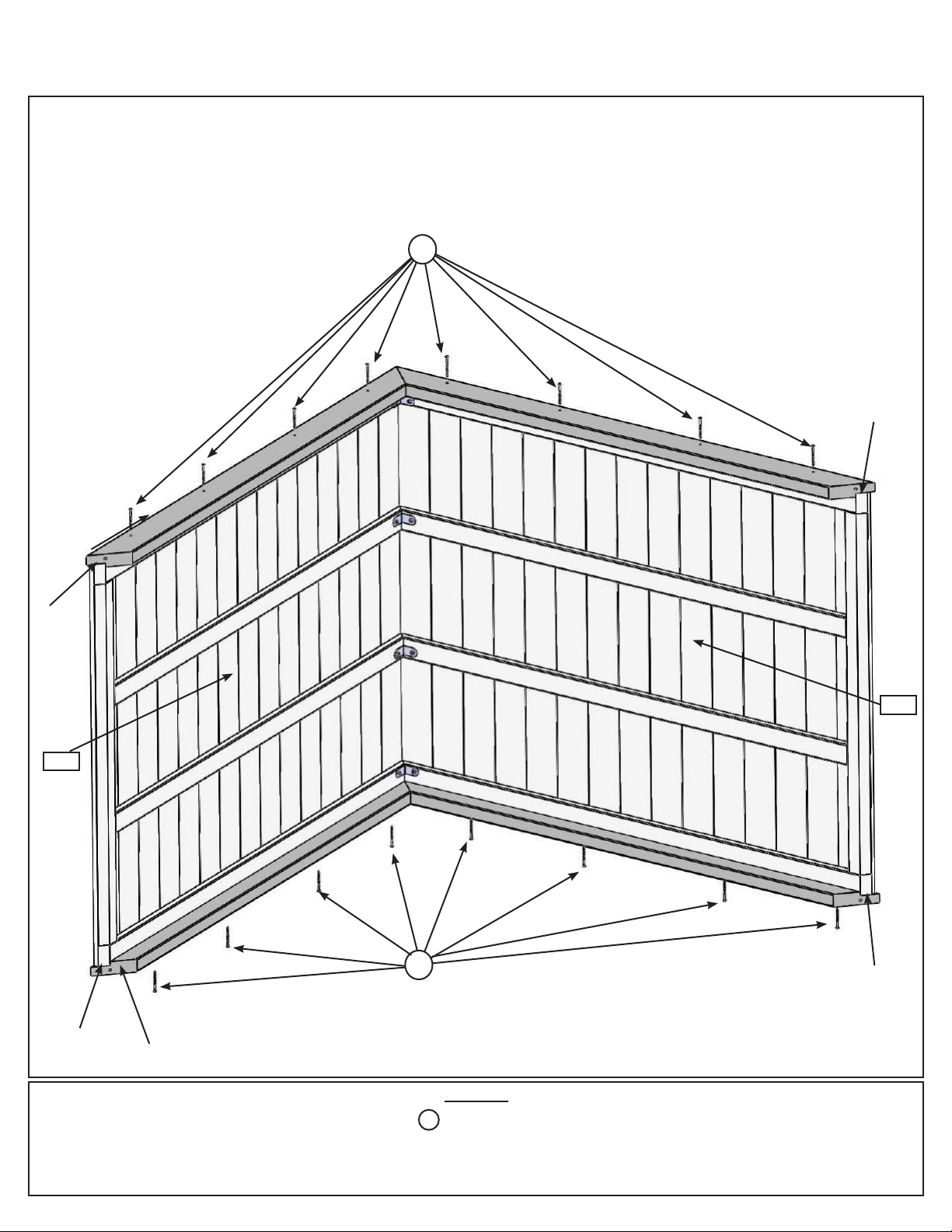
Step 35: Roof Assembly
Part 2
C: Place 1 Roof Rafter Assembly against one side so the peaks meet and the ends of the roof supports are ush
with the ends of the roof panels. Attach with 8 (S11) #8 x 2” Wood Screws. (g. 35.4)
D: Attach the second Roof Rafter Assembly on the opposite side, peaks to meet and ends are ush with 8 (S11)
#8 x 2” Wood Screws. (g. 35.4)
S11
Fig. 35.4
Flush
Flush
351
Flush
350
S11
Flush
Roof Rafter
Assembly
Hardware
S11
16 x #8 x 2” Wood Screw
Page 82
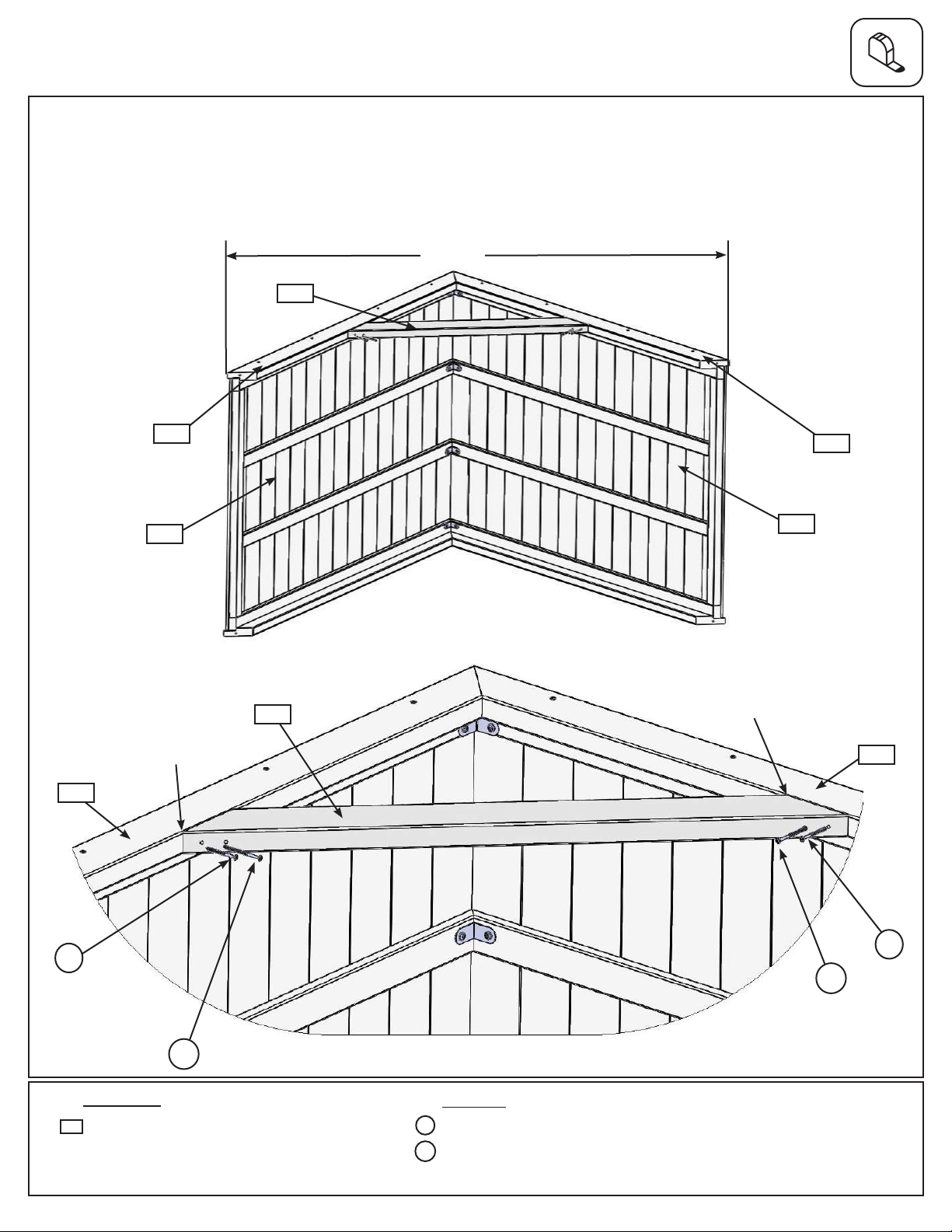
Step 36: Back Gable Assembly
Part 1
A: Measure from the outside edges of each (340) Roof Rafter on the Back side of the the Roof Assembly so
the distance is 72”. (g. 36.1)
B: Maintain the 72” then tight to each rafter attach (360) Back Gable Support with 1 (S3) #8 x 2-1/2” Wood
Screw and 1 (S11) #8 x 2” Wood Screw per side. (g. 36.1 and 36.2)
72”
Fig. 36.1
Fig. 36.2
340
351
Tight
360
360
Back
340
350
Front
Tight
340
340
S11
S11
S3
S3
Wood Parts
360
1 x Back Gable Support 1-1/4 x 3 x 34-1/2”
2 x #8 x 2-1/2” Wood Screw
2 x #8 x 2” Wood Screw
Hardware
S3
S11
Page 83
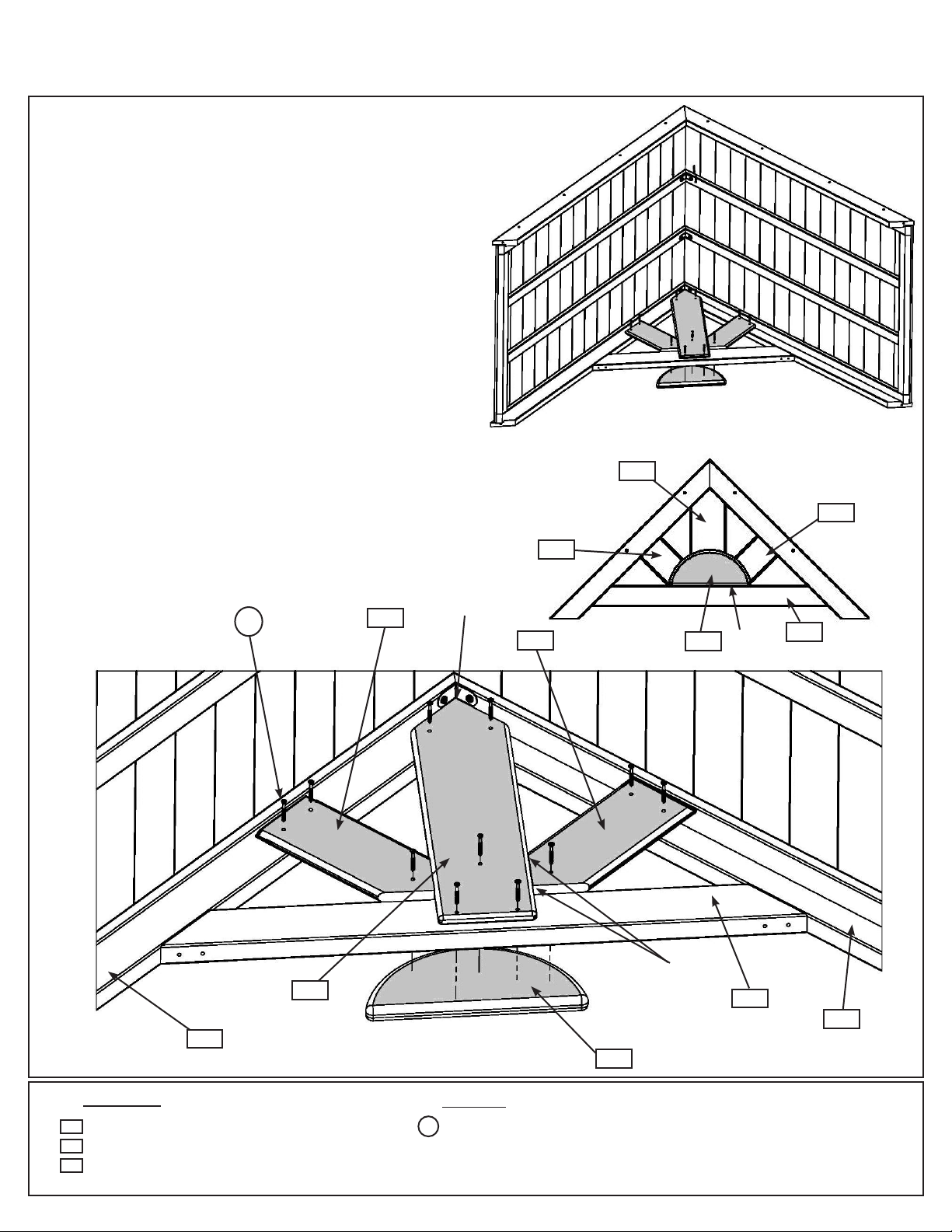
Step 36: Back Gable Assembly
Part 2
C: Turn the Roof Assembly over so the Back side is on
the bottom. Place (361) BK Centre Gable on top of (360)
Back Gable Support and on both (340) Roof Rafters,
tight to the peak, then attach with 2 (S20) #8 x 1-3/8”
Wood Screws. (g. 36.3, 36.4 and 36.5)
D: Place (362) Starburst Centre centred under (361)
BK Centre Gable, tight to the top of (360) Back Gable
Support then attach (361) BK Centre Gable to (362)
Starburst Centre with 1 (S20) #8 x 1-3/8” Wood Screw.
(g. 36.3, 36.4 and 36.5)
E: Place 1 (363) Sunburst Side tight to each side of
(361) BK Centre Gable and to the top of (360) Back
Gable Support then attach to (362) Starburst Centre with
1 (S20) #8 x 1-3/8” Wood Screw per board. (g. 36.3,
36.4 and 36.5)
F: Attach (361) BK Centre Gable and both (363)
Sunburst Sides to the (340) Roof Rafters with 2 (S20) #8
x 1-3/8” Wood Screw per board. (g. 36.4)
Fig. 36.3
Inside View
Fig. 36.4
Outside View
363
Back
361
363
Fig. 36.5
Inside View
340
S20
x 11
361
363
Tight
363
362
Tight
362
Tight
360
360
340
Wood Parts
361
1 x BK Centre Gable 1 x 6 x 19”
362
1 x Starburst Centre 5/4 x 6 x 12”
363
2 x Sunburst Side 1 x 5 x 10”
11 x #8 x 1-3/8” Wood Screw
Hardware
S20
Page 84
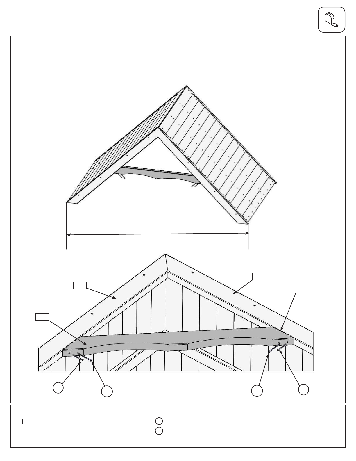
Step 37: Front Gable Assembly
A: Measure from the outside edges of each (340) Roof Rafter on the Front side of the Roof Assembly so the
distance is 72”. (g. 37.1)
B: Maintain the 72” then tight to each rafter attach (370) Mid Gable Support with 1 (S3) #8 x 2-1/2” Wood
Screw and 1 (S11) #8 x 2” Wood Screw per side. (g. 37.1 and 37.2)
Fig. 37.2
Fig. 37.1
340
Back
Front
72”
340
Tight
370
S11
S3
Wood Parts
370
1 x Mid Gable Support 1-1/4 x 3 x 34-1/2”
Hardware
S3
2 x #8 x 2-1/2” Wood Screw
S11
2 x #8 x 2” Wood Screw
S3
S11
Page 85
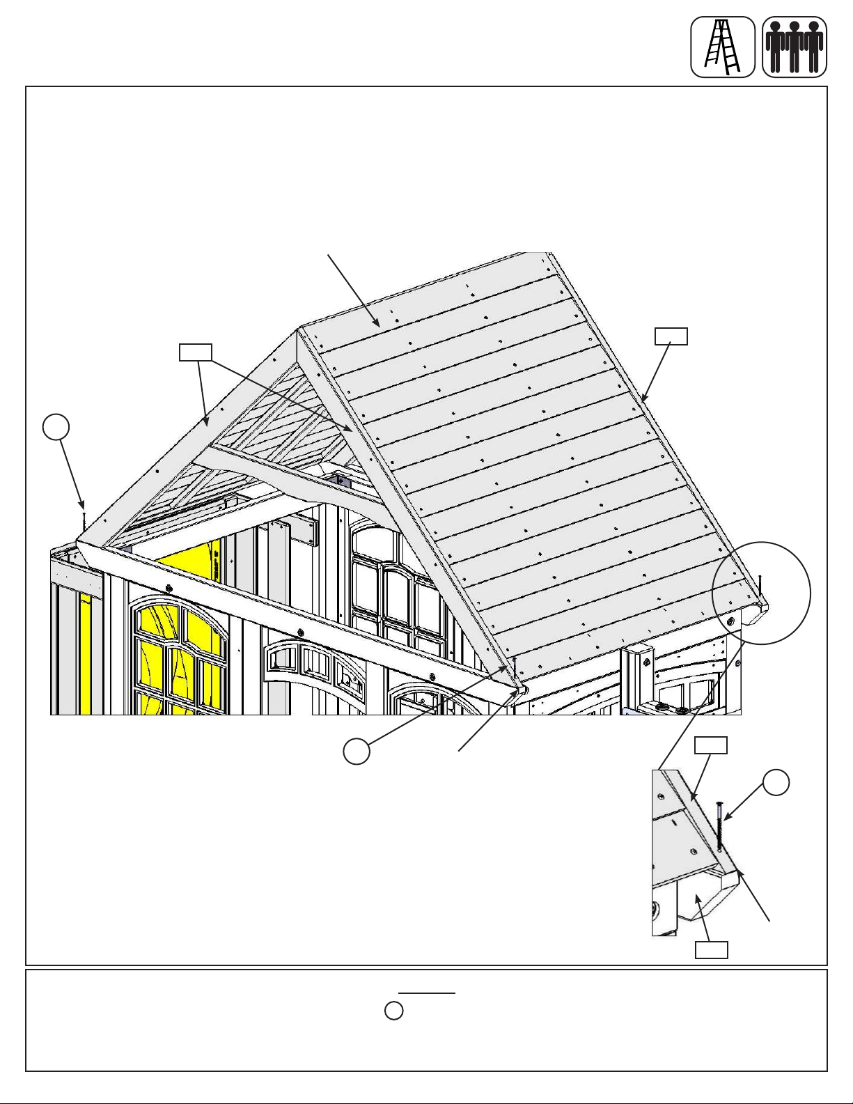
Step 38: Attach Roof Assembly to Fort
Part 1
A: With 2 people on the ground and at least 1 person in the fort, lift the Roof Assembly up and over the Front
side of the fort. Guide the Roof Assembly onto the fort so all four (340) Roof Rafters sit ush to the outside
edges of (062) Roof Supports. Notice which way the openings face. (g. 38.1)
B: Attach (340) Roof Rafter to (062) Roof Supports with 1 (S3) #8 x 2-1/2” Wood Screw per corner. (g. 38.1
and 38.2)
Roof Assembly
Back
Fig. 38.1
340
340
S3
Swing Wall
Front
S3
Hardware
S3
4 x #8 x 2-1/2” Wood Screw
Flush
Fig. 38.2
340
S3
Flush
062
Page 86
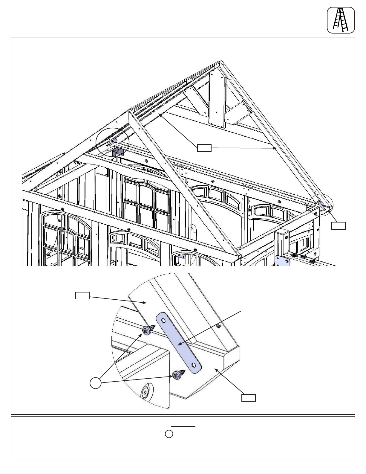
Step 38: Attach Roof Assembly to Fort
Part 2
C: On the Back of the assembly attach each (340) Roof Rafter to (062) Roof Support with 1 Small Jamb Mount
per side using 2 (S0) #8 x 7/8” Truss Screws per mount. (g. 38.3 and 38.4)
Back
Parts removed
for clarity
Fig. 38.3
340
Fig. 38.4
062
340
Small Jamb
Mount
S0
062
Hardware
Hardware
S0
4 x #8 x 7/8” Truss Screw
Other Parts
2 x Small Jamb Mount
Page 87
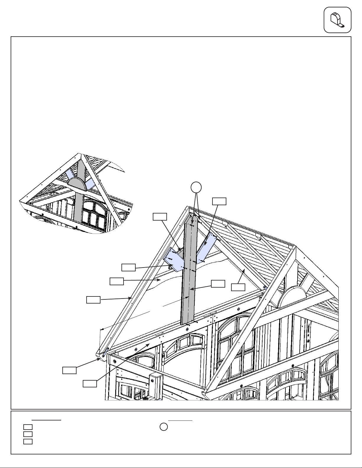
36"
Step 39: Front Roof Assembly
Part 1
A: On the Front, from inside the assembly, measure 36” from the end of (062) Roof Support. Place (390)
FR Centre Gable on top of (051) Front Wall Panel so the middle is at the 36” mark. Attach to (062) Roof
Support, (370) Mid Gable Support and (340) Roof Rafters with 5 (S20) #8 x 1-3/8” Wood Screws. (g. 39.1
and 39.2)
B: From the outside of the assembly place (362) Starburst Centre on top of (370) Mid Gable support then
attach (390) FR Centre Gable to (362) Starburst Centre with 1 (S20) #8 x 1-3/8” Wood Screw. (g. 39.1 and
39.2)
C: Place 1 (363) Sunburst Side tight to each side of (390) FR Centre Gable and tight to each (340) Roof
Rafter then attach to (362) Starburst Centre and (340) Roof Rafters with 3 (S20) #8 x 1-3/8” Wood Screws
per board. (g. 39.1 and 39.2)
Fig. 39.1
Outside View
Front
340
370
363
362
S20
x 12
363
390
Parts removed
for clarity
Fig. 39.2
Inside View
340
062
051
Wood Parts
390
1 x FR Centre Gable 1 x 6 x 34-15/16”
362
1 x Starburst Centre 5/4 x 6 x 12”
363
2 x Sunburst Side 1 x 5 x 10”
12 x #8 x 1-3/8” Wood Screw
Hardware
S20
Page 88
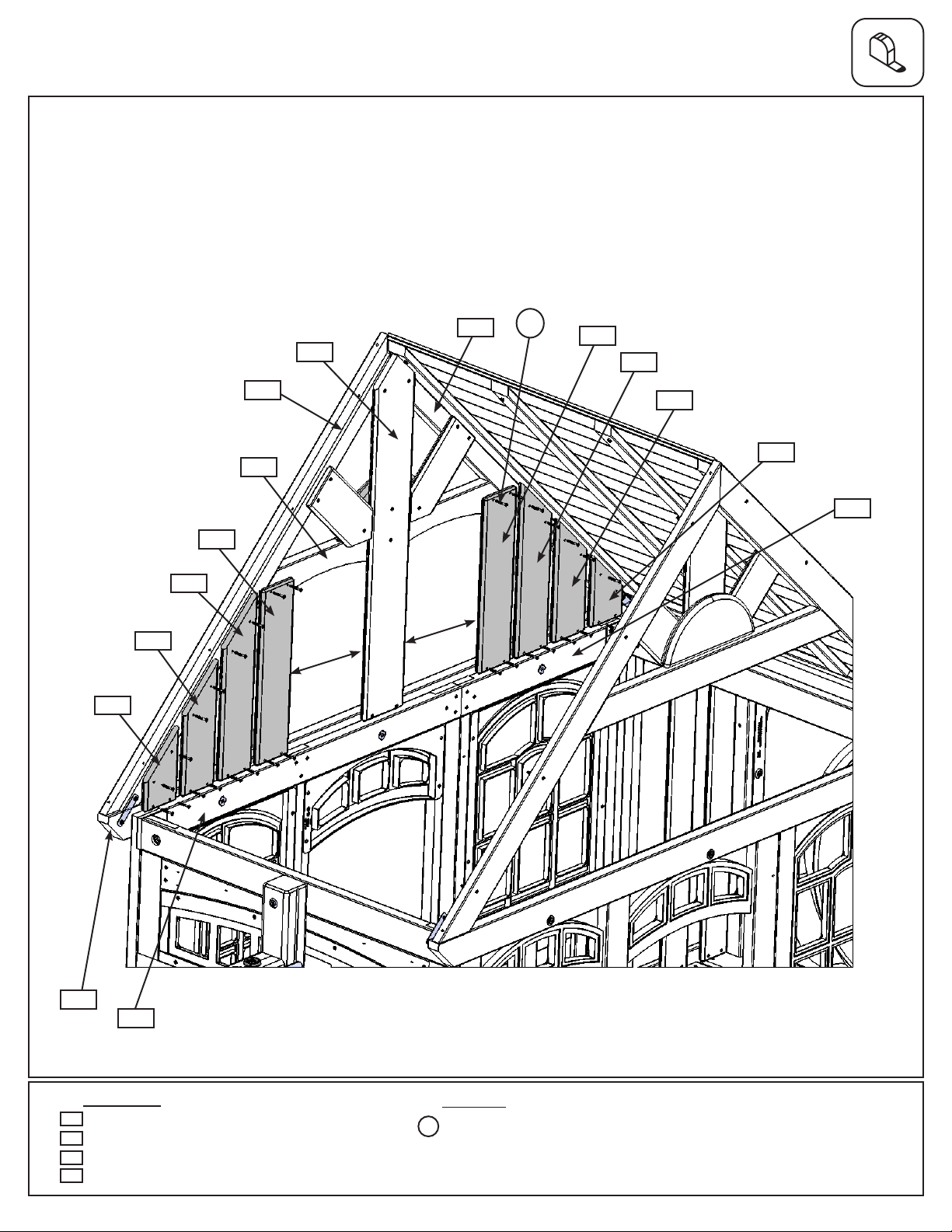
Step 39: Front Roof Assembly
Part 2
D: From inside the assembly measure 10” from each side of the (390) FR Centre Gable then place 1 (391)
End Gable A on top of (051) Front Wall Panel and (042) Narrow Front Panel at each 10” mark and attach to
(062) Roof Support, (370) Mid Gable Support and (340) Roof Rafters with 4 (S20) #8 x 1-3/8” Wood Screws
per board. (g. 39.3)
E: On each side beside (391) End Gable A, evenly space 1 (392) End Gable D then 1 (393) End Gable B
and lastly 1 (394) End Gable C. Attach each board to (062) Roof Support, (340) Roof Rafters and (051)
Front Wall Panel or (042) Narrow Front Panel with 4 (S20) #8 x 1-3/8” Wood Screws per board. (g. 39.3)
Fig. 39.3
Inside View
394
393
392
391
340
370
390
10”
10”
340
S20
x 32
391
392
393
Parts removed
for clarity
394
042
062
051
Wood Parts
391
2 x End Gable A 1 x 5 x 17-1/8”
392
2 x End Gable D 1 x 5 x 17-1/8”
393
2 x End Gable B 1 x 5 x 12-1/8”
394
2 x End Gable C 1 x 5 x 7-1/8”
32 x #8 x 1-3/8” Wood Screw
Hardware
S20
Page 89
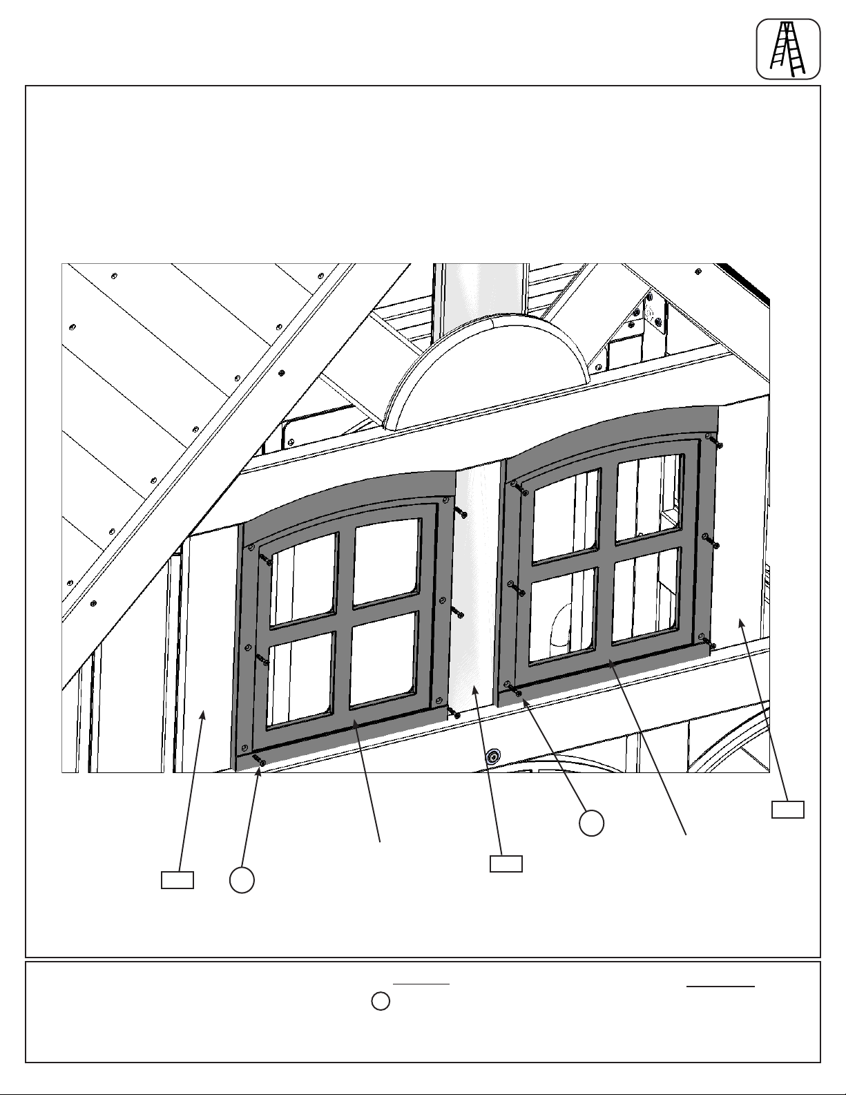
Step 39: Front Roof Assembly
Part 3
F: From outside the assembly place a 2 x 2 Panel Window in each opening and attach to (390) FR Centre
Gable and each (391) End Gable A with 6 (S33) #8 x 1” Wood Screws per window. (g. 39.4)
Fig. 39.4
Outside View
S33
x 6
2 x 2 Panel
Window
391
S33
x 6
Hardware
S33
12 x #8 x 1” Wood Screw
390
2 x 2 Panel
Window
Other Parts
2 - 2 x 2 Panel Window
391
Page 90
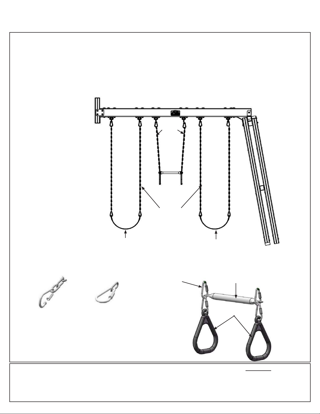
Step 40: Attach Swings
A: Using 1 Threaded Quick Link per chain, join 1 Long Swing Chain to each side of the Swing Belt Seat.
Make sure to close the Threaded Quick Link tightly using an adjustable wrench. (g. 40.1 and 40.2).
B: Using 1 Threaded Clip per chain, join the Short Swing Chain to the Acro Bar. Using another Threaded Clip,
join the Acro Handle to the Acro Bar. Make sure to close the Threaded Clip tightly using an adjustable wrench.
(g. 40.2 and 40.3)
C: Attach the other end of the swing chains to the Spring Loaded Quick Links attached to the Heavy Duty
Swing Hangers. (g. 40.1)
Short
Fig. 40.1
Swing
Chain
Caution: Threaded Quick Links
must be installed with the gate
completely down covering
the threads and tighten as
instructed. (g. 40.2)
Fig. 40.2
Threaded Quick Links
attach to seat and Acro
Tighten Threaded Quick
Link using adjustable
bar.
Swing Seat
wrench
Long Swing Chain
Threaded
Quick Link
Swing Seat
Fig. 40.3
Acro Bar
Acro Handles
Other Parts
1 x Acro Bar
2 x Acro Handle
2 x Swing Belt Seat
2 x Short Swing Chain
4 x Long Swing Chain
8 x Threaded Quick Link
Page 91
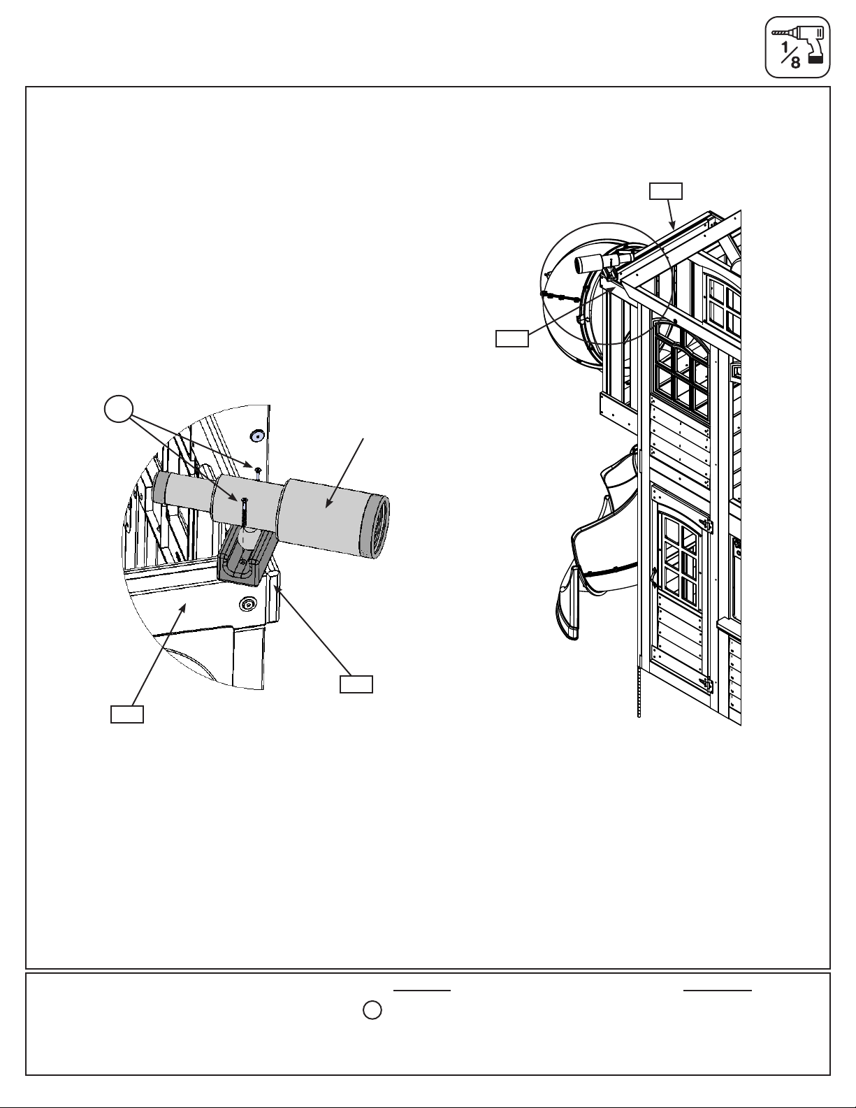
Step 41: Attach Telescope
A: On the front, outer corner of the Crowsnest pre-drill with a 1/8” drill bit then attach Telescope to (200)
Crowsnest Top and (212) Crowsnest Side with 2 (S11) #8 x 2” Wood Screws. (g. 41.1 and 41.2)
Fig. 41.2
S11
Telescope
Fig. 41.1
212
200
212
200
Hardware Other Parts
S11
1 x Telescope 2 x #8 x 2” Wood Screw
Page 92
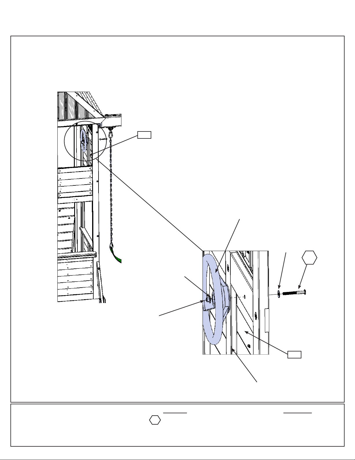
Step 42: Attach Steering Wheel
A: On the front upright of (050) SW Wall Panel attach Steering Wheel with 1 (WB10) 5/16 x 2-5/8” Wafer Bolt
(with at washer x 2 and lock nut). The bolt is attached from the outside of the assembly. (g. 42.1 and 42.2)
B: If you purchased a Preston refer to Step 47.
Fig. 42.1
050
Window
removed for
clarity
Fig. 42.2
Inside View
Steering Wheel
5/16” Flat
Washer
WB10
5/16” Flat
Washer
Front
5/16”
Lock Nut
050
front
upright
Hardware Other Parts
WB10
1 x 5/16 x 2-5/8” Wafer Bolt
(5/16”atwasherx2,5/16”locknut)
1 x Steering Wheel
Page 93
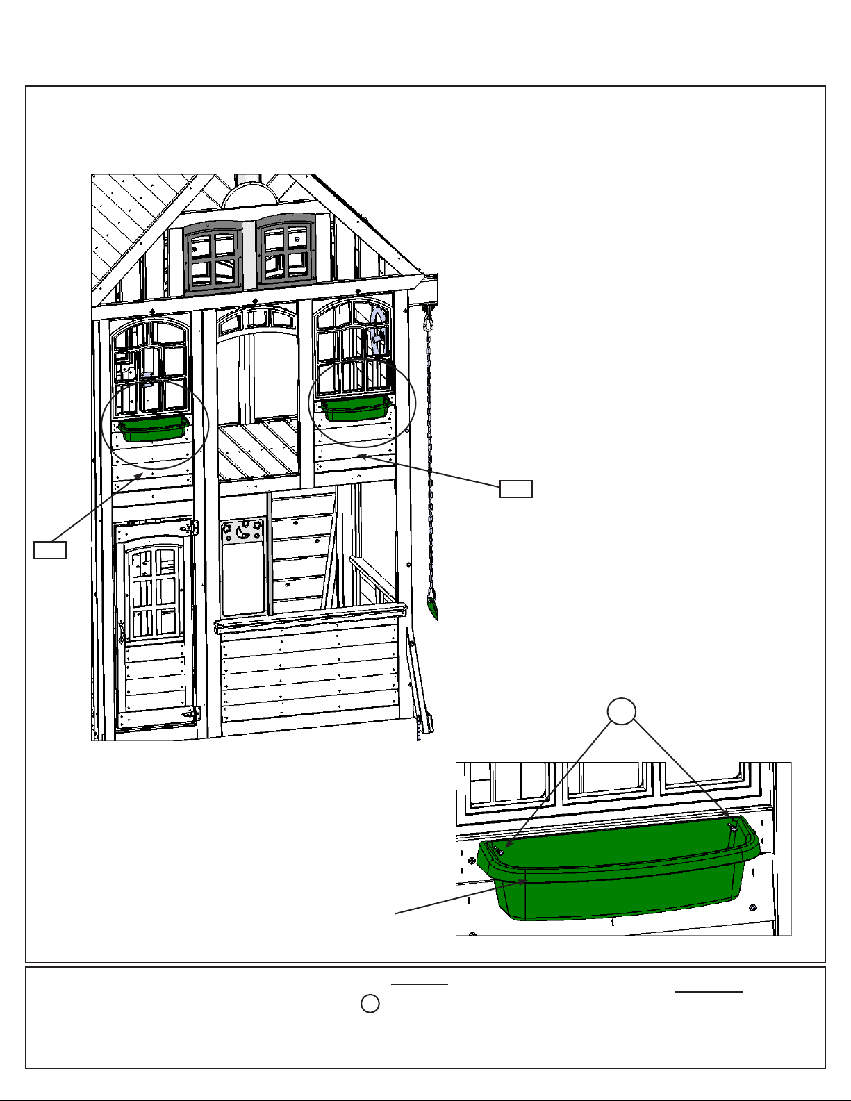
Step43:AttachFlowerBoxes(Brockwell/TwinMountainLodge)
A: On the front of the assembly place 1 Flower Box under each window and attach to (051) Front Wall Panel
and (042) Narrow Front Panel with 2 (S13) #6 x 5/8” Pan Screws per Flower Box. (g. 43.1 and 43.2)
Fig. 43.1
042
051
S13
Fig. 43.2
Flower Box
Hardware
S13
4 x #6 x 5/8” Pan Screw
Other Parts
2 x Flower Box
Page 94
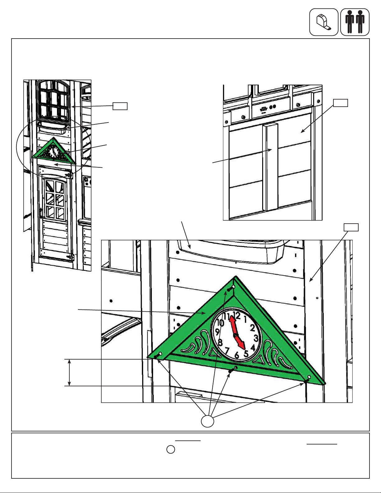
(Brockwell / Twin
Step 44: Attach Clock Assembly
A: On the front of the assembly measure 3-1/4” up from the bottom of the centre board in (042) Narrow
Front Panel then place the Gable Clock Assembly at the marked location centred under the Flower Box then
attach with 4 (S10) #8 x 1” Pan Screws. Make sure the top screw connects to the block at the back of (042)
Narrow Front Panel. (g. 44.1, 44.2 and 44.3)
MountainLodge)
Fig. 44.1
042
Flower
Box
Gable Clock
Assembly
Centre
Board
Outside View
Fig. 44.3
Fig. 44.2
Inside View
042
Top screw must
connect to this
board.
Flower Box
042
Gable Clock
Assembly
3-1/4”
S10
Hardware
S10
4 x #8 x 1” Pan Screw
Other Parts
1 x Gable Clock Assembly
Page 95
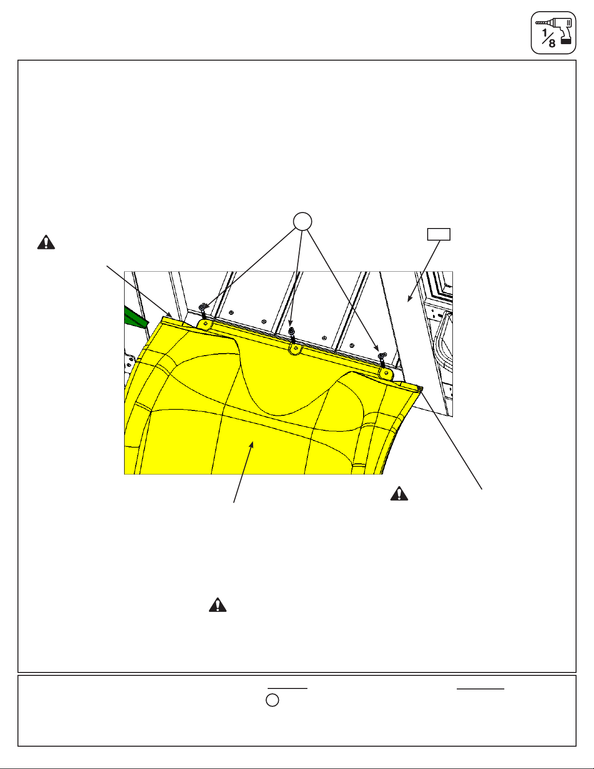
(Brockwell / Twin
Step 45: Attach Slide to Fort
Note: Pre-drill all holes using a 1/8” drill bit before installing the pan screws.
A: Place Slide centred in the opening of the (051) Front Wall Panel. Slide must be tight to the outside of (051)
Front Wall Panel. (g. 45.1)
B: Attach slide to fort using 3 (S7) #12 x 2” Pan Screws. (g. 45.1)
Fig. 45.1
Warning! Must be tight to
(051)FrontWallPanelonbothsides
MountainLodge)
S7
051
Slide
(051)FrontWallPanelonbothsides
Warning! Check entire play
center for bolts protruding beyond
T-Nuts. Use extra washers to
eliminate this condition.
Warning! Must be tight to
Hardware
S7
3 x #12 x 2” Pan Screw
Other Parts
1 x Slide
Page 96
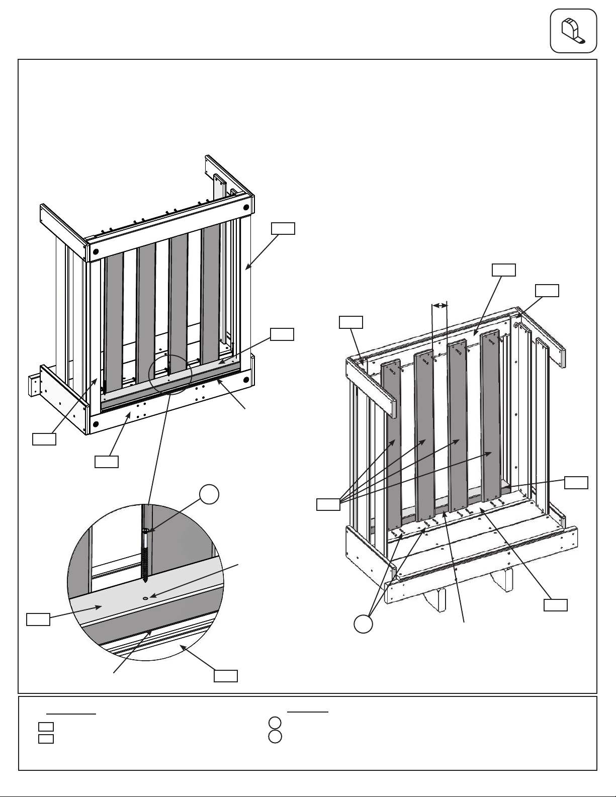
Step 46: Crowsnest Front Wall Assembly
(Brockwellonly)
A: In between (204) Crowsnest Spacers, ush to the front of (202) Crowsnest Front place (460) Wall Board
Support and attach with 3 (S3) #8 x 2-1/2” Wood Screws. (g. 46.1 and 46.2)
B: Evenly space 4 (230) Cedar Walls in between both (201) Upright Crowsnests so the gap between each
measures approximately 2-3/8”. Make sure each (230) Cedar Wall is tight to (220) Crowsnest Gap Board then
attach to (203) Crowsnest Short and (240) Wall Board Support with 4 (S20) #8 x 1-3/8” Wood Screws per board.
(g. 46.3)
Fig. 46.1
Outside View
204
202
S3
Flush
204
460
230
201
Bevelled edges
facing out.
2-3/8”
(approx.)
Fig. 46.3
Inside View
203
201
460
Fig. 46.2
Note: Hole location
towards front.
220
460
Flush
Wood Parts
460
1 x Wall Board Support 1-1/4 x 2-1/4 x 25-1/2”
230
4 x Cedar Wall 1 x 4 x 29”
202
Hardware
S3
3 x #8 x 2-1/2” Wood Screw
S20
16 x #8 x 1-3/8” Wood Sc
S20
rew
x 4 per
board
Tight
Page 97
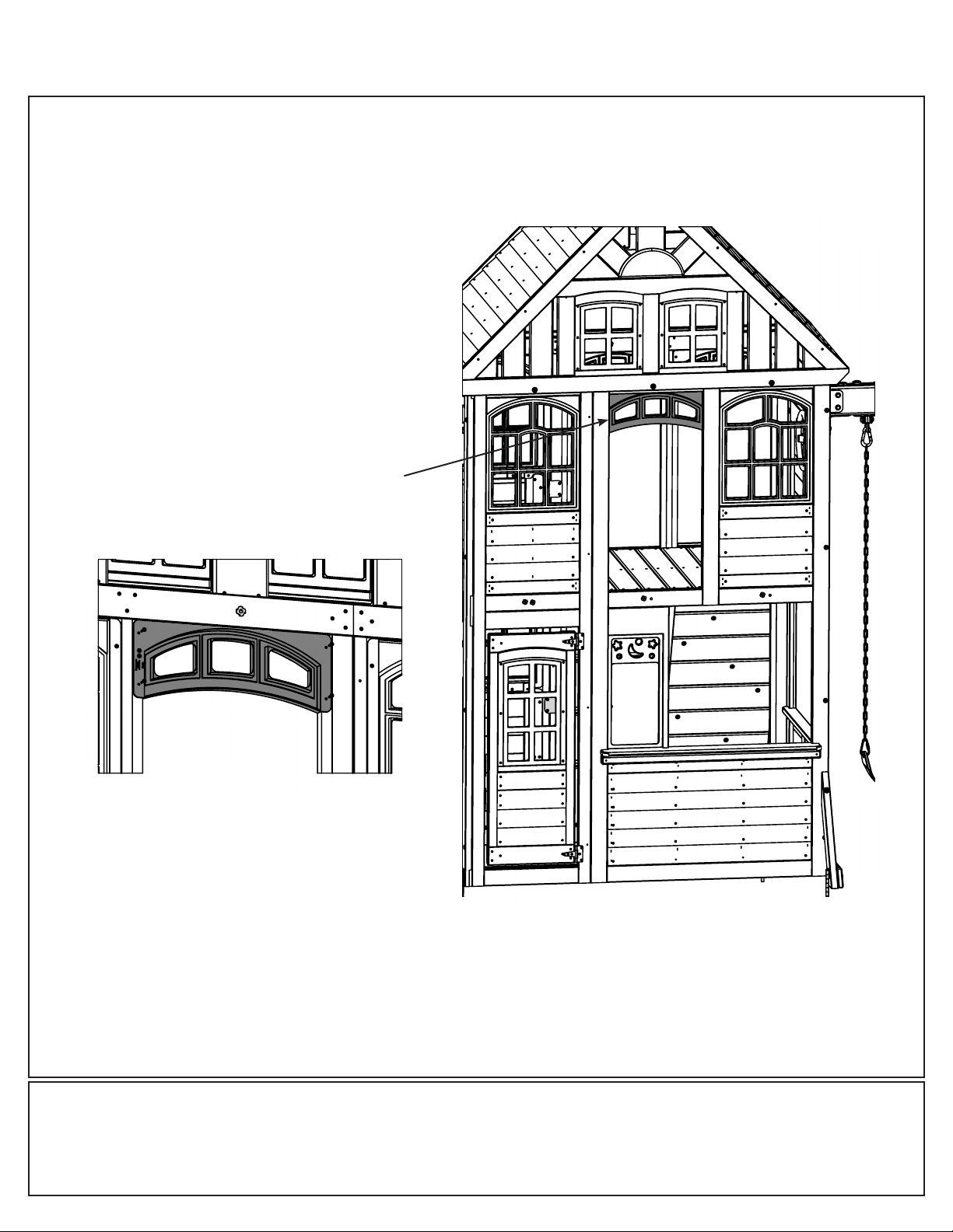
Step 47: Attach Upper Window Insert
(Prestononly)
Part 1
A: Remove Transom from Front Wall Panel by removing 4 (S0) #8 x 7/8” Truss Screws. (g. 47.1 and 47.2)
Transom
Fig. 47.2
Inside View
Fig. 47.1
Page 98

Step 47: Attach Upper Window Insert
(Prestononly)
Part 2
B: Attach (470) Upper Window Insert to Front Wall Panel from the inside with 9 (S0) #8 x 7/8” Truss Screws.
(g. 47.3 and 47.4)
470
Fig. 47.4
Inside View
Wood Parts
470
1 x Upper Window Insert
S0
Hardware
9 x #8 x 7/8” Truss Screw
S0
Fig. 47.3
Page 99
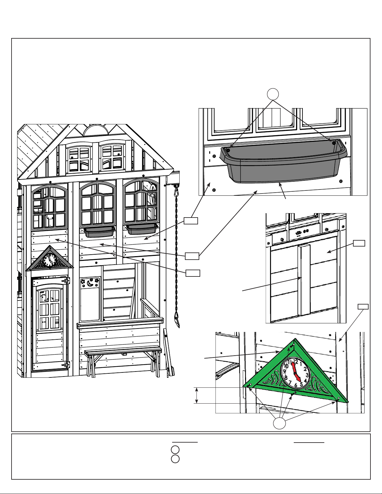
Step 48: Attach Gable Clock and Flower Boxes
(Prestononly)
A: On the front of the assembly place 1 Flower Box under centre and right windows and attach to (051) Front
Wall Panel and (470) Upper Window Insert with 2 (S13) #6 x 5/8” Pan Screws per Flower Box. (g. 48.1 and 48.2)
B: On the front of the assembly measure 3-1/4” up from the bottom of the centre board in (042) Narrow Front
Panel then place the Gable Clock Assembly at the marked location then attach with 4 (S10) #8 x 1” Pan Screws.
Make sure the top screw connects to the block at the back of (042) Narrow Front Panel. (g. 48.1, 48.3 and 48.4)
S13
Outside View
051
470
042
Top screw must
connect to this
board.
Gable Clock
Assembly
Fig. 48.2
Flower Box
042
Outside View
Fig. 48.3
042
Fig. 48.1
4 x #6 x 5/8” Pan Screw
4 x #8 x 1” Pan Screw
3-1/4”
Hardware
S13
S10
Outside View
Fig. 48.4
S10
Other Parts
2 x Flower Box
1 x Gable Clock Assembly
Page 100
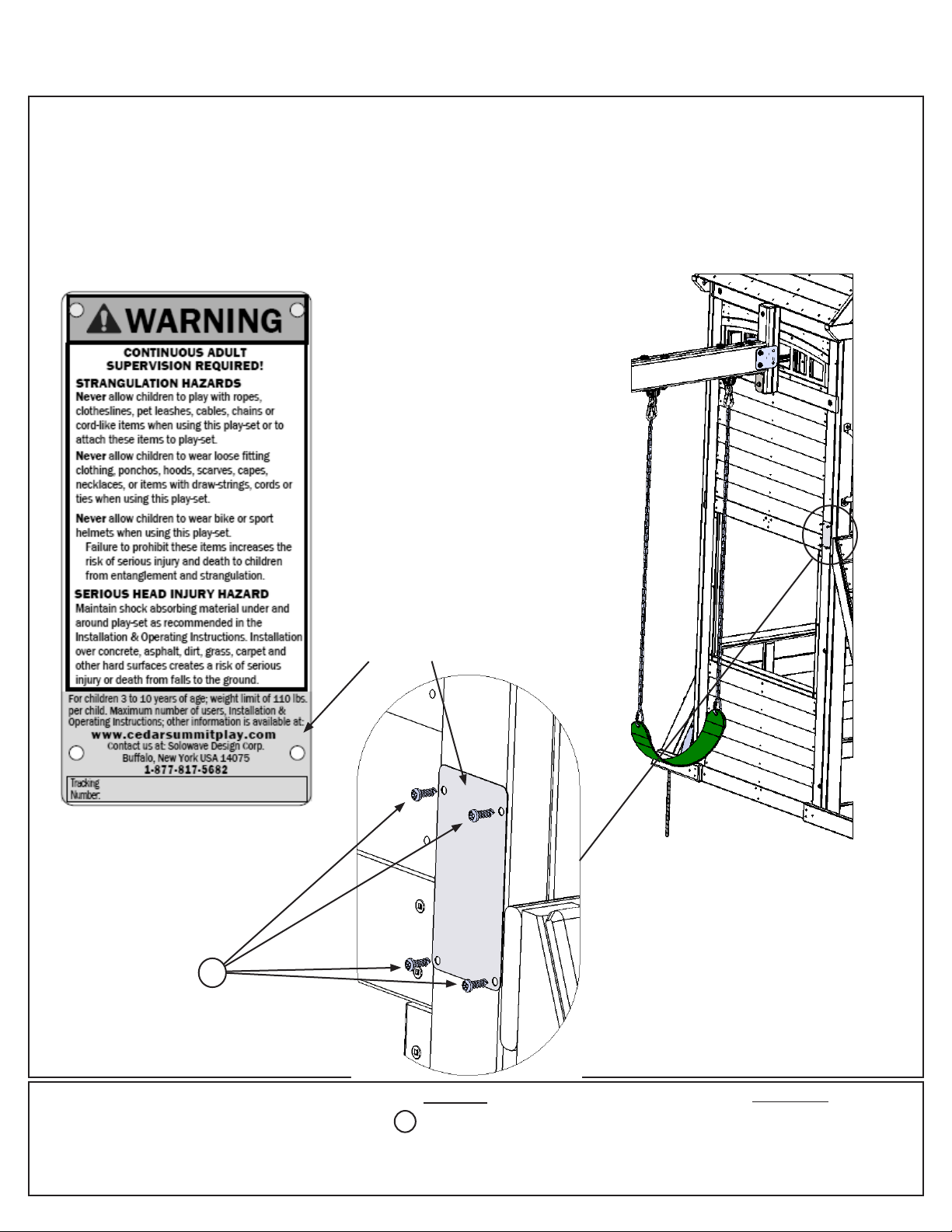
Final Step: Attach I.D. Plaque
ATTACHTHISWARNING&I.D.PLAQUE
TO THIS LOCATION ON YOUR PLAY
EQUIPMENT!
This provides warnings concerning safety and
important contact information. A Tracking Number
is provided to allow you to get critical information
or order replacement parts for this specific model.
ATTACHTHISWARNING&I.D.PLAQUE
TO THIS LOCATION ON YOUR PLAY
EQUIPMENT!
This provides warnings concerning safety and
important contact information. A Tracking Number
is provided to allow you to get critical information or
order replacement parts for this specic model.
A: Attach I.D. Plaque
- Cedar Summit to a
location on your set that
is easily seen and read
by a supervising adult
using 4 (S13) #6 x 5/8”
Pan Screws as shown
below.
S13
I.D. Plaque Cedar Summit
Hardware
S13
4 x #6 x 5/8” Pan Screw
Other Parts
1 x I.D. Plaque - Cedar Summit
 Loading...