

Page 1

Model M
-
049
Kwik
-
Way Products Inc.
Valve Seat Insert Tool
Instruction Manual and Parts List
800-553-5953 • 319-377-9421 • 319-377-9101 (FAX)
Copyright © 2008 Equipment, specifications, options and accessories subject to change without notice.
500 57th Street, Marion, Iowa 52302 USA
www.kwik-way.com
Page 2

Page 3

Kwik
-
Way Products Inc.
Street
Marion, Iowa 52302 USA
5953 (US)
9101 (FAX)
way.com
Purchaser Warranty
Kwik-Way Products guarantees all parts of its equipment, to the original purchaser, for one full year from date of
recorded warranty (except as provided below) against defects in material or workmanship when the equipment
is installed in strict accordance with pertinent specifications and procedures.
Kwik-Way Products will repair and/or replace free of charge all such defective parts only when returned to the
factory in Marion, Iowa, with shipping charges prepaid.
This guaranty does not cover damage caused by accident, abuse or improper installation, nor repair or
replacement of parts worn or consumed in normal operation of the machine.
Additionally, this guaranty does not cover such items as dresser diamonds, ball bearings, grinding wheels, belts,
carbide tool bits and other accessory items, except at the discretion of the company. The guaranty on electric
motors or electrical component parts is for a period of ninety days from date of delivery.
This guaranty is at no time intended to mean the entire machine.
KEEP FOR YOUR RECORDS:
Model:
Serial Number:
Date of Delivery:
Office Hours: 7:30 to 5:00 Central Time
500 57
th
1-800-553-
319-377-9421 • 319-377-
www.kwik-
Page 4

Page 5

Kwik
-
Way Products Inc.
Street
Marion, Iowa 52302 USA
5953 (US)
(FAX)
way.com
Receiving Shipment
Upon taking delivery of your machine, carefully inspect the assembly before removing the crating and packing
materials.
If evidence of damage exists, contact the shipper and Kwik-Way Product Inc. immediately. Although Kwik-Way
Product Inc. is not responsible for damage incurred during transit, you will be provided assistance in preparation
and filing of any necessary claims.
CAREFULLY READ THIS MANUAL BEFORE ATTEMPTING TO SET-UP OR OPERATE THIS MACHINE.
Important Note:
Always have your serial number ready when communicating with Kwik-Way Products Inc. regarding parts or
service.
Keep this manual in a safe place.
Date Received
Serial Number
Office Hours: 7:30 to 5:00 Central Time
500 57
th
1-800-553-
319-377-9421 • 319-377-9101
www.kwik-
Page 6

SAFETY FIRST
This manual has been prepared for the owner and those responsible for the maintenance of this machine. Its
purpose aside from proper maintenance and operations is to promote safety through the use of accepted
practice. READ THE SAFETY AND OPERATING INSTRUCTIONS THOROUGHLY BEFORE OPERATING
THE MACHINE.
In order to obtain maximum life and efficiency from your machine; follow all the instructions in the operating
manuals carefully.
The specifications put forth in this manual were in effect at the time of publication. However, owing to Kwik-Way
Product’ policy of continuous improvement, changes to these specifications may be made at any time without
obligation.
SAFETY INSTRUCTIONS
1. Read, understand and follow the safety and operating instructions found in this manual. Know the limitations
and hazards associated with operating the machine.
Page 7

2. Eye Safety: Wear an approved safety face shield, goggles or safety glasses to protect eyes when operating
the machine.
3. Grounding the Machine: Machines equipped with three prong grounding plugs are so equipped for your
protection against shock hazards and should be plugged directly into a properly grounded three-prong
receptacle in accordance with national electrical codes and local codes and ordinances. A grounding adapter
may be used. If one is used, the green lead should be securely connected to a suitable electrical ground such
as a ground wire system. Do not cut off the grounding prong or use an adapter with the grounding prong
removed.
4. Work Area: Keep the floor around the machine clean and free of tools, tooling, stock scrap and other foreign
material and oil, grease or coolant to minimize the danger of tripping or slipping. Kwik-Way recommends the
use of anti-skid floor strips on the floor area where the operator normally stands and that each machine's work
area be marked off. Make certain the work area is well lighted and ventilated. Provide for adequate workspace
around the machine.
5. Guards: Keep all machine guards in place at all times when machine is in use.
6. Do Not Overreach: Maintain a balanced stance and keep your body under control at all times.
7. Hand Safety: NEVER wear gloves while operating this machine.
8. Machine Capacity: Do not attempt to use the machine beyond its stated capacity or operations. This type
use will reduce the productive life of the machine and could cause the breakage of parts, which could result in
personal injury.
9. Avoid Accidental Starting: Make certain the main switch is in the OFF position before connecting power to
the machine.
10. Careless Acts: Give the work you are doing your undivided attention. Looking around, carrying on a
conversation and horseplay are careless acts that can result in serious injury.
11. Job Completion: If the operation is complete, the machine should be emptied and the work area cleaned.
12. Disconnect All Power and Air to Machine before performing any service or maintenance.
13. Replacement Parts: Use only Kwik-Way replacement parts and accessories; otherwise, warranty will be null
and void.
14. Misuse: Do not use the machine for other than its intended use. If used for other purposes, Kwik-Way
Product Inc. disclaims any real or implied warranty and holds itself harmless for any injury or loss that may result
from such use.
Page 8
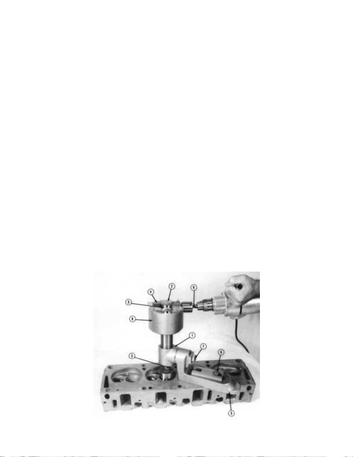
Kwik-Way Products Inc. Instructional Manual & Parts List: M-049
OPERATION AND MAINTENANCE MANUAL
For Kwik-Way Seat Insert Tool
CLEAN MACHINE:
Clean gearbox unit and all accessories to remove all surplus oil, grease and rust preventive materials.
OPERATING INSTRUCTIONS:
1. Select proper size seat insert cutter and cutter driver for seat insert ring to be installed
2. Select proper size Kwik-way tapered arbor to fit valve guide and insert firmly into guide
3. Place the base assembly (Item 5) on the combustion surface of the cylinder head (or block) so the large
hole in the gear case swivel (Item 1) lines up approximately with the arbor
a. The base should be placed so that it can be clamped to the cylinder head (or block) as close to
the arbor as possible
b. Tighten the clamping screw or screws (Item 6) only enough to allow the base to slide freely
c. Loosen the screw (Item 7) that clamps the gear case swivel (Item 1) to the base until it is free to
rotate
4. Locate the base for proper alignment by inserting the seat driver assembly (Item 5) into the large hole in
the gear case swivel and down over the upper part of the arbor: (NOTE A)
a. Adjust the base and gear case swivel until the seat driver assembly slides freely over the arbor
b. Clamp the gear case swivel firmly to the base, then clamp the base to the head (or block)
c. Check to be sure the seat driver assembly still slides freely on the arbor
d. Slight readjustment of the base may be necessary if there is binding on the arbor
Page 1
Page 9

Kwik-Way Products Inc. Instructional Manual & Parts List: M-049
NOTE A: When using Kwik-Way 7/16” (11.11mm) top arbors or others having different diameters on the top
portion of the arbor, a cutter adapter sleeve must be used over the top of the arbor when aligning the gear case
swivel and base, and while using the seat insert cutter. The use of this sleeve is necessary because the inside
diameter of the cutter drive shaft (Item 3) of the gear case assembly (Item 8) is 5/8” (15.87mm), the same as the
center hole of the various seat insert cutters.
• A 7/16” (11.11mm) inside diameter by 5/8” (15.87mm) outside diameter cutter adapter sleeve
assembly (part number 049-0129-50) normally is furnished as standard equipment for use with
7/17” top Kwik-Way arbors
• Cutter Adapter Sleeves: Adapts 5/8” I.D. bore of cutters, cutter drive shaft and seat driver to top
diameter of Kwik-Way arbors and pilots of other manufacturers. Any one cutter adapter sleeve
will be furnished with Model “M” basic set (specify make of seat grinder and top size of arbor or
pilot)
• Other cutter adapter sleeve assemblies are available as listed below
ADAPTER SLEEVE ASSEMBLIES:
049-0129-50 7-16” (Kwik-Way)
049-0129-18 3-8” (Kwik-Way)
049-0129-42 13-32” (Kwik-Way)
049-0129-18 3/8” (B&D, Van Dorn, US Tool, Skill, KO Lee, Thor and US Government .375)
049-0129-50 7/16” (Hall Toledo)
049-0129-34 .385 (Sioux)
049-0129-77 .5725 (Sioux)
NOTE B: To line up the tool on engines with valve guides at an angle or inclined to the top of the head (or
block), it will be necessary to set the base in the direction of the line of valves – in other words, parallel to the
position of the crankshaft
• You will find the swivel casting offset from the center to take care of valve seats which are nearer
one row of studs than the other
• By turning this casting half way around, the large hole is shifted relative to the base
• Consequently, it will sometimes be necessary to turn this casting half way around on reversing the
direction of the base
• For engines with valve guides square with the combustion surface of the cylinder head (or block),
the base can set in any position – wherever it happens to be most convenient for clamping
• On cylinder heads that have large combustion chamber cavities with little flat surface for clamping
the base, the 049-0280-08 adapter plate assembly (Item 1) should be used to insure a solid
clamping surface (this assembly is optional equipment)
5. Remove the seat driver assembly from the gear case swivel and remove arbor from valve guide using
the arbor puller (Item 17)
6. Lubricate the inside of the cutter adapter sleeve and the top part of the arbor with light oil
a. Place the seat insert cutter in position over the valve seat and insert the arbor through the
center hole of the seat insert cutter into the valve guide and set firmly with the arbor puller
b. Place the cutter adapter sleeve over the arbor and through the center hole of the seat insert
cutter, pushing in downward until it stops
7. Insert the shank of the gear case assembly into the Gear Case Swivel, push assembly downward so
that the driving dogs of the cutter drive shaft fully engage in the driving slots of the seat insert cutter.
Page 2
Page 10

Kwik-Way Products Inc. Instructional Manual & Parts List: M-049
8. Rotate the knurled handwheel on top of the gear case assembly in a counterclockwise direction until the
seat insert ring to be installed will slip in between the bottom of the knurled handwheel and the
machined upper surface of the gear case assembly housing at point “X”.
a. Turn the knurled handwheel clockwise until the seat insert ring is lightly clamped by the bottom
side of the knurled handwheel
b. Remove ring. The gear case assembly is now fed downward until the bottom of the knurled
handwheel touches the top of the gear case assembly housing and will produce a counterbore
that is the same depth as the thickness of the seat insert ring
c. Check to be sure that the driving dogs in the cutter drive shaft are fully engaged with the slots in
the seat insert cutter, then rotate the gear case assembly so that the driving shank of the gear
case assembly is in the most convenient position for using the electric drill motor.
d. Firmly clamp the gear case swivel by tightening cap screw
9. Rotate small knurled handwheel having projecting handle in a clockwise direction until the plunger
under the larger knurled handwheel clicks up into engagement. This action engages the automatic
down feed.
10. Connect electric drill to driver shank, as shown and tighten chuck by hand.
a. The electric drill should be 3/8” capacity or larger with an output speed of no more that 800
R.P.M.
CAUTION: MAKE CERTAIN THAT DRILL MOTOR IS PROPERLY GROUNDED BEFORE OPERATING.
b. Start drill motor.
c. The power feed will disengage when the bottom of the feed handwheel reaches the top of the
Gear case assembly housing, but it is important to allow the seat insert cutter to turn several full
revolutions to insure a perfectly flat surface just before the feed handwheel is fully bottomed out
on the top of the gear case assembly housing.
d. Turn feed handwheel by hand the last half turn to bottom out.
11. After finishing the above operation, remove the gear case assembly, the arbor and cutter. Do not
disturb the position of the swivel casting and base, as they furnish the guide for the seat driver.
12. After removing all chips from the counterbored surface, place the seat insert ring in position to be driven
in.
a. Put the proper size driver adapter on top of the seat ring.
b. Push the driver down through the swivel casting against the adapter.
c. Use a heavy hammer for driving the seat in. It is best practice to drive it in with one heavy blow
rather than with several light ones.
d. Be sure the insert ring bottoms in the counterbore. This can be readily determined by the
difference in the sound while using the hammer.
e. The seat ring is chamfered on the one side to help it enter the counterbore. Place the chamfer
side down when driving the ring.
Page 3
Page 11
Kwik-Way Products Inc. Instructional Manual & Parts List: M-049
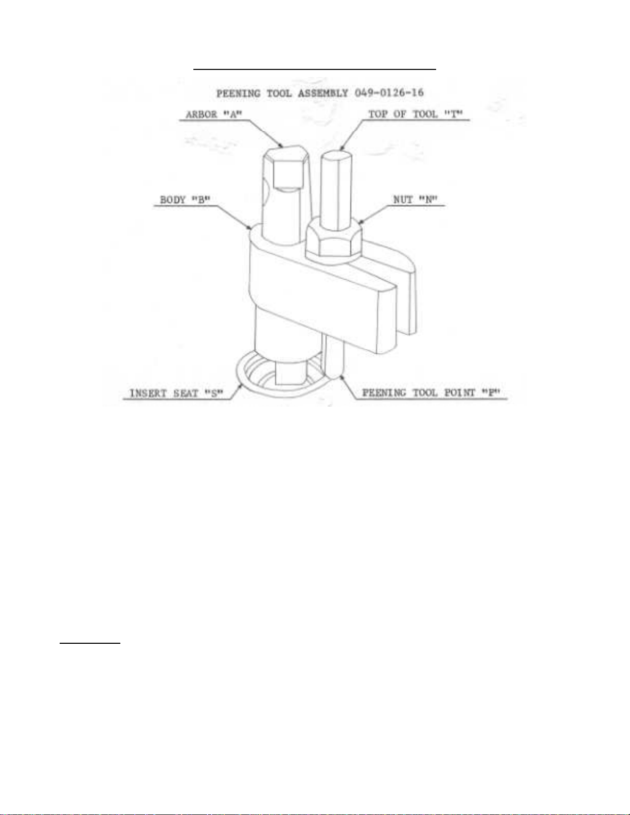
PEENING TOOL ASSEMBLY 049-0126-16
The Peening Tool Assembly is available as extra equipment with the KWIK-WAY Seat Insert Tool allowing the
insert ring to be peened in. This tool is shown in position for use in the above figure.
After the seat “S” has been driven into place and the Base and Swivel Assembly has been removed, simply
replace the arbor “A”. Loosen nut “N”, adjust the tool so the point “P” is about 1/32” outside the outer edge of
the Seat “S” and retighten nut “N”. Be sure the straight edge of the chisel point of the peening tool is away from
the ring and the beveled edge is towards the ring. Finally, tap the top of the tool “T” lightly with a hammer,
gradually turning the tool around the arbor until the entire seat has been peened.
LUBRICATION
The gear case of these tools is filled with grease which will take care of all lubrication, except for the bearings
on the shaft which connect to the drill chuck. These bearings are provided with oil cups which should frequently
be filled with light or medium machine oil. Mobilux #1 or equivalent is recommended for interior mechanism.
About one ounce should be added at six moth intervals.
REMEMBER
1. ALWAYS CLAMP THE BASE AS NEAR TO THE SEAT BEING SERVICED AS POSSIBLE
2. BE SURE EVERYTHING IS CLAMPED BEFORE STARTING THE ELECTRIC DRILL.
Page 4
Page 12

Kwik-Way Products Inc. Instructional Manual & Parts List: M-049
LIST OF MOST COMMONLY ORDERED SERVICE PARTS
When ordering parts, please specify KWIK-WAY Valve Seat Ring Replacement Tool Model “M” and the Serial
Number.
• 049-0129-50 7/16 Cutter Adapter Sleeve Assembly
• See cutters listed below.
NOTE: When ordering cutters other than sizes in your original set, order seat driver adapter to match new cutter.
Carbide Cutters and Driver Adapters:
Decimal
Diameter
1.0000” 1” 25.40 049-0100-00
1.0625” 1-1/16” 26.99 049-0106-25 049-0834-08 1.0625 (26.99mm)
1.1250” 1-1/8” 28.58 049-0112-50 049-0834-16 1.1250 (28.58mm)
1.1875” 1-3/16” 30.16 049-0118-75 049-0834-24 1.1875 (30.17mm)
1.2500” 1-1/4” 31.75 049-0125-00 049-0834-25 1.2500-1.4128 (31.75-35.89mm)
1.2860” 32.67 049-0128-60 049-0834-25 1.2500-1.4128 (31.75-35.89mm)
1.3125” 1-5/16” 33.34 049-0131-25 049-0834-25 1.2500-1.4128 (31.75-35.89mm)
1.3438” 1-11/32” 34.14 049-0134-38 049-0834-25 1.2500-1.4128 (31.75-35.89mm)
1.3750” 1-3/8” 34.93 049-0137-50 049-0834-25 1.2500-1.4128 (31.75-35.89mm)
1.3785” 35.02 049-0137-85 049-0834-25 1.2500-1.4128 (31.75-35.89mm)
1.4125” 35.88 049-0141-25 049-0834-25 1.2500-1.4128 (31.75-35.89mm)
1.4230” 36.15 049-0142-30 049-0834-25 1.2500-1.4128 (31.75-35.89mm)
1.4375” 1-7/16” 36.52 049-0143-75 049-0834-43 1.4375-1.5735 (36.52-39.97mm)
1.4630” 37.16 049-0146-30 049-0834-43 1.4375-1.5735 (36-52-39.97mm)
1.4915” 37.89 049-0149-15 049-0834-43 1.4375-1.5735 (36.52-39.97mm)
1.5000” 1-1/2” 38.10 049-0150-00 049-0834-43 1.4375-1.5735 (36.52-39.97mm)
1.5310” 38.89 049-0153-10 049-0834-43 1.4375-1.5735 (36.52-39.97mm)
1.5625” 1-9/16” 39.69 049-0156-25 049-0834-43 1.4375-1.5735 (36.52-39.97mm)
1.5655” 39.77 049-0156-55 049-0834-43 1.4375-1.5735 (36.52-39.97mm)
1.5735” 39.97 049-0157-35 049-0834-43 1.4375-1.5735 (36.52-39.97mm)
1.6250” 1-5/8” 41.28 049-0162-50 049-0834-62 1.6250-1.8105 (41.28-45.99mm)
1.6495” 41.90 049-0164-95 049-0834-62 1.6250-1.8105 (41.28-45.99mm)
1.6875” 1-11/16” 42.87 049-0168-75 049-0834-62 1.6250-1.8105 (41.28-45.99mm)
1.6905” 42.94 049-0169-05 049-0834-62 1.6250-1.8105 (41.28-45.99mm)
1.7000” 43.18 049-0170-00 049-0834-62 1.6250-1.8105 (41.28-45.99mm)
1.7180” 43.64 049-0171-80 049-0834-62 1.6250-1.8105 (41.28-45.99mm)
1.7340” 44.05 049-0173-40 049-0834-62 1.6250-1.8105 (41.28-45.99mm)
1.7350” 44.07 049-0173-50 049-0834-62 1.6250-1.8105 (41.28-45.99mm)
1.7500” 1-3/4” 44.45 049-0175-00 049-0834-62 1.6250-1.8105 (41.28-45.99mm)
1.8105” 45.99 049-0181-05 049-0834-62 1.6250-1.8105 (41.28-45.99mm)
1.8125” 1-13/16” 46.04 049-0181-25 049-0834-81 1.8125-1.9960 (46.04-50.7mm)
1.8370” 46.66 049-0183-70 049-0834-81 1.8125-1.9960 (46.04-50.7mm)
1.8410” 46.77 049-0184-10 049-0834-81 1;8125-1.9960 (46.04-50.7mm)
1.8470” 46.92 049-0184-70 049-0834-81 1.8125-1.9960 (46.04-50.7mm)
1.8500” 46.99 049-0185-00 049-0834-81 1.8125-1.9960 (46.04-50.7mm)
1.8570” 47.17 049-0185-70 049-0834-81 1.8125-1.9960 (46.04-50.7mm)
1.8600” 47.25 049-0186-00 049-0834-81 1.8125-1.9960 (46.04-50.7mm)
1.8750” 1-7/8” 47.63 049-0187-50 049-0834-81 1.8125-1.9960 (46.04-50.7mm)
1.9090” 48.49 049-0190-90 049-0834-81 1.8125-1.9960 (46.04-50.7mm)
1.9190” 48.75 049-0191-90 049-0834-81 1.8125-1.9960 (46.04-50.7mm)
1.9290” 49.0 049-0192-90 049-0834-81 1.8125-1.9960 (46.04-50.7mm)
Fractional
Diameter
MM
Cutter Part
Number
Corresponding
Driver Adapt.
Adapter Range
Decimal
Adapter RangeMM
Page 5
Page 13

Kwik-Way Products Inc. Instructional Manual & Parts List: M-049
2.4140
Carbide Cutters and Driver Adapters
Decimal
Diameter
1.9375” 1-15/16” 49.22 049-0193-75 049-0835-72 1.9375-1.9960 (46.04-50.7mm)
1.9960” 50.7 049-0199-60 049-0835-72 1.9375-1.9960 (46.04-50.7mm)
2.0000” 2” 50.8 049-0200-00 049-0834-98 2.0000-2.1670 (50.8-55.05mm)
2.0060” 50.96 049-0200-60 049-0834-98 2.0000-2.1670 (50.8-55.05mm)
2.0095” 51.05 049-0200-95 049-0834-98 2.0000-2.1670 (50.8-55.05mm)
2.0160” 51.21 049-0201-60 049-0834-98 2.0000-2.1670 (50.8-55.05mm)
2.0195” 51.3 049-0201-95 049-0834-98 2.0000-2.1670 (50.8-55.05mm)
2.0295” 51.55 049-0202-95 049-0834-98 2.0000-2.1670 (50.8-55.05mm)
2.0430” 51.9 049-0204-30 049-0834-98 2.0000-2.1670 (50.8-55.05mm)
2.0625” 2-1/16” 52.39 049-0206-25 049-0834-98 2.0000-2.1670 (50.8-55.05mm)
2.0845” 52.95 049-0208-45 049-0834-98 2.0000-2.1670 (50.8-55.05mm)
2.0970” 53.27 049-0209-70 049-0834-98 2.0000-2.1670 (50.8-55.05mm)
2.1250” 2-1/8” 53.98 049-0212-50 049-0834-98 2.0000-2.1670 (50.8-55.05mm)
2.1440” 54.46 049-0214-40 049-0834-98 2.0000-2.1670 (50.8-55.05mm)
2.1470” 54.54 049-0214-70 049-0834-98 2.0000-2.1670 (50-8-55.05mm)
2.1570” 54.79 049-0215-70 049-0834-98 2.0000-2.1670 (50.8-55.05mm)
2.1670” 55.05 049-0216-70 049-0834-98 2.0000-2.1670 (50.8-55.05mm)
2.1875” 2-3/16” 55.57 049-0218-75 049-0834-19 2.1875-
2.2500” 2-1/4” 57.15 049-0225-00 049-0834-19 2.1875-2.4140 (55.57-61.32mm)
2.3125” 2-5/16” 58.74 049-0231-25 049-0834-19 2.1875-2.4140 (55.57-61.32mm)
2.3750” 2-3/8” 60.33 049-0237-50 049-0834-19 2.1875-2.4140 (55.57-61.32mm)
2.3840” 60.56 049-0238-40 049-0834-19 2.1875-2.4140 (55.57-61.32mm)
2.3940” 60.81 049-0239-40 049-0834-19 2.1875-2.4140 (55.57-61.32mm)
2.4040” 61.07 049-0240-40 049-0834-19 2.1875-2.4140 (55.57-61.32mm)
2.4140” 61.32 049-0241-40 049-0834-19 2.1875-2.4140 (55.57-61.32mm)
2.4375” 2-7/16” 61.92 049-0243-75 049-0834-44 2.4375-2.6250 (61.92-66.68mm)
2.4510” 62.26 049-0245-10 049-0834-44 2.4375-2.6250 (61.92-66.68mm)
2.4670” 62.67 049-0246-70 049-0834-44 2.4375.2.6250 (61.92-66.68mm)
2.4870” 63.17 049-0248-70 049-0834-44 2.4375-2.6250 (61.92-66.68mm)
2.5000” 2-1/2” 63.5 049-0250-00 049-0834-44 2.4375-2.6250 (61.92-66.68mm)
2.5625” 2-9/16” 65.09 049-0256-25 049-0834-44 2.4375-2.6250 (61.92-66.68mm)
2.6250” 2-5/8” 66.68 049-0262-50 049-0834-44 2.4375-2.6250 (61.92-66.68mm)
2.7500” 2-3/4” 69.85 049-0275-00 049-0834-73 2.7500-2.9375 (69.85-74.62mm)
2.8750” 2-7/8” 73.03 049-0287-50 049-0834-73 2.7500-2.9375 (69.85-74.62mm)
2.9375” 2-15/16” 74.62 049-0293-75 049-0834-73 2.7500-2.9375 (69.85-74.62mm)
3.0000” 3” 76.2 049-0300-00 049-0834-73 2.7500-2.9375 (69.85-74.62mm)
Fractional
Diameter
MM
Cutter Part
Number
Corresponding
Driver Adapt.
(cont):
Adapter Range
Decimal
Adapter RangeMM
(55.57-61.32mm)
IMPORTANT NOTE:
1. Fractional size cutters produce counter bores corresponding to the cutter size, for example, to install a
seat marked 1 ½” O.D. use a 1 ½” cutter.
2. When ordering decimal size cutters specify measured O.D. of seat and give “press” or “interference” fit
recommended by seat ring manufacturer.
3. Only the cutters listed are stock sizes. Cutters in any fractional/decimal size not listed can be supplied
on special order.
4. Cutters larger that 2 ½” are not recommended for power feed. Feed should be made slowly, by hand,
so as not to overtake the feed unit.
Note: When cutters are ordered (other than in sets listed on the following pages) seat driver adapters are not
included. When ordering adapters for fractional size cutters 1 ½, 1 5/8, 2 3/8, etc., order adapter same size as
cutter or up to 1/16” under. When ordering adapters for decimal size cutters 1.671, 1.985, 2.470, etc., order
adapter next fractional size under cutter (adapters are actually 1 1/16” smaller on O.D. than size marked on
them.)
Page 6
Page 14

Kwik-Way Products Inc. Instructional Manual & Parts List: M-049
Parts List
Page 7
Page 15

Kwik-Way Products Inc. Instructional Manual & Parts List: M-049
Parts List
ITEM PART NUMBER DESCRIPTION REQ’D
1 049-0280-08 Adapter Plate Assembly 1
4 049-0261-02 Seat Driver Plug 1
5 049-0260-13 Seat Driver – Long 1
8 049-0205-20 Gear Case Swivel (Used only/Item #11) 1
9 000-0107-90 7/16-14 x 1 ¼ Hex Head C.S. (Used only/Item #8) 1
11 049-0201-63 Base (Used only/Item #8) 1
14 049-0202-01 Base Clamp 1
15 049-0206-43 Washer (Used only/Item #11) 1
16 000-0113-04 5/8-18 x 2 ¼ Hex Head C.S. (Used only/Item #8) 1
17 049-0365-15 7/16 Arbor Extractor Pin & Handle Assembly 1
19 000-1070-18 ½ - 20 Hex Finished Jam Nut 1
21 049-0126-08 Peening Tool 1
22 049-0128-02 Peening Washer 1
23 049-0127-05 Peening Tool Body – Standard 1
24 049-0208-48 Gear Case Cover 1
25 000-0168-70 5/16 – 18 x 1 ¾ Socket Head Capscrew 2
26 000-1802-38 Compression Spring 1
27 049-0245-41 Plunger 1
28 000-7101-13 3/32 x 3/8 Roll Pin 1
29 000-9200-45 Oilless Bushing 1
30 000-1900-12 ¼ Snap Lid Oiler 2
32 000-1542-45 1/8 Socket Pipe Plug 1
33 000-2002-39 Gasket 1
34 049-0207-08 Gear Case 1
35 000-2201-16 Oil Seal 1
36 000-9200-53 Oilless Bushing 1
37 049-0209-02 Oil Plug 1
38 000-0168-29 5/16-18 x 1 ½ Socket Head Cap Screw 1
39 025-0151-00 Spanner Wrench Pin 2
40 049-0218-01 Feed Handwheel 1
41 000-0485-26 ¼ - 20 x 3/8 Cup Point Socket Set Screw 1
41 000-0405-41 ¼ - 20 x ½ Cup Point Socket Set Screw 1
42 049-0220-69 Feed Screw Nut (Used only/Item #43 & #44) 1
43 049-0217-63 Feed Screw (Used only/Item #42 & #44) 1
44 049-0219-68 Feed Screw Ratchet (Used only/Item #42 & #43) 1
Page 8
Page 16

Kwik-Way Products Inc. Instructional Manual & Parts List: M-049
ITEM PART NUMBER DESCRIPTION REQ’D
45 000-7300-33 #3 Woodruff Key 1
49 000-7104-07 3/16 x ¾ Clevis Pin 1
50 049-0232-43 Pawl 1
51 000-1840-80 Tension Spring 1
52 000-7203-64 Ratchet Sleeve Pin 1
53 000-1092-66 6 – 32 Hex Machine Screw Nut 1
54 000-0220-20 6 – 32 x 3/8 Flat Head Machine Screw 1
55 049-0238-04 Ratchet Sleeve 1
56 049-0246-06 Tripper Pin 1
57 000-0222-68 8 – 32 x 3/8 Flat Head Machine Screw 1
58 049-0243-04 Tripper Shaft Crank 1
59 049-0242-07 Tripper shaft 1
60 049-0244-01 Tripper Shaft Locating Pin 1
61 049-0241-00 Power Feed Tripper 1
62 049-0241-85 Tripper Set Screw 1
63 000-0487-63 5/16-18 x 5/16 Cup Point Socket Set Screw 2
64 049-0252-03 Spiral Pinion Shaft Bushing 2
65 049-0250-09 Spiral Pinion 1
66 000-1690-48 Thrust Bearing 1
72 049-0258-31 Pin 1
73 000-7000-29 ¼ x 1 Dowel Pin 1
74 000-7000-70 ¼ x ½ Dowel Pin 2
75 049-0253-35 Body 1
76 049-0255-48 Collar 1
77 049-0254-40 Shank 1
78 000-0482-67 10 - 24 x 3/16 Cup Point socket Set Screw 1
79 049-0213-48 Drive Shaft Sleeve 1
80 000-2100-99 3/8 Steel Ball 2
81 049-0212-40 Drive Shaft Stud 1
82 049-0224-09 Gear Key 1
83 049-0223-01 Drive Shaft Gear 1
85 049-0223-01 Drive Shaft Gear 1
85 049-0214-45 Cutter Drive Shaft - 4” 1
86 049-0249-40 Spiral Gear 1
87 049-0247-03 Thrust Washer 1
88 049-0225-14 Compound Gear Assembly 1
89 000-1067-63 7/16 - 20 Hex Finished Jam Nut 1
Page 9
Page 17

Kwik-Way Products Inc. Instructional Manual & Parts List: M-049
ITEM PART NUMBER DESCRIPTION REQ’D
90 049-0228-83 Pivot Bushing 1
91 049-0228-40 Compound Gear Pivot 1
93 000-1836-28 Tru Arc Ring 1
94 049-0231-46 Eccentric 1
95 000-0222-68 8 – 32 x 3/8 Flat Head Machine Screw 2
97 049-0129-50 Adapter Sleeve Assembly – 7/16 1
98 049-0239-01 Ratchet Sleeve Stop 1
99 049-0248-43 Pinion Shaft 1
Page 10
Page 18

Kwik
-
Way Products Inc.
Street, Marion, Iowa 52302 USA
5953
9101 (FAX)
way.com
way.com
500 57
th
319-377-9421 • 319-377-
www.kwik-
service@kwik-
800-553-
 Loading...