

Page 1
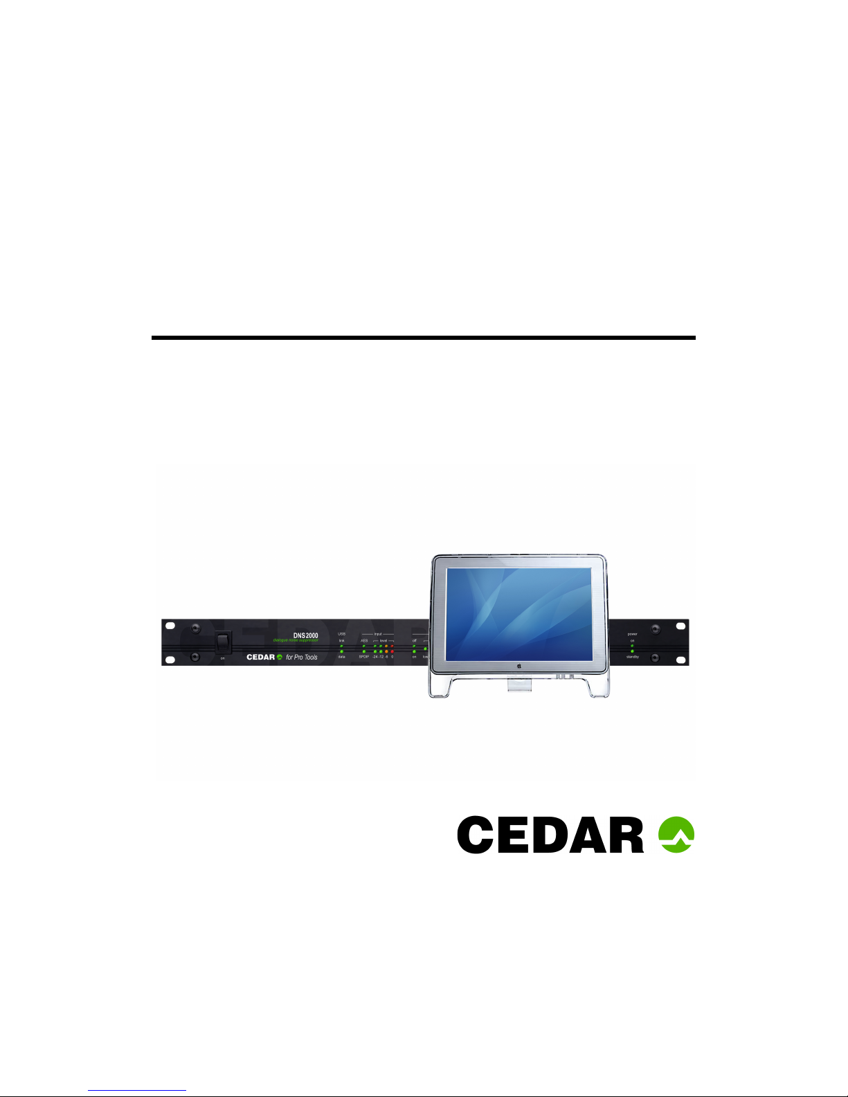
DNS2000
Dialogue noise suppressor
CEDAR Audio Limited
www.cedaraudio.com
Manual v1.7 – 31 October 2012
Page 2

The page left blank
Page 3

TABLE OF CONTENTS
Introduction.................................................................................... 1
System requirements....................................................................... 2
Safety instructions........................................................................... 3
Assumed knowledge ........................................................................ 4
Contact information ......................................................................... 5
Setting up the DNS2000 hardware..................................................... 7
Installing the DNS Control System – Mac ............................................ 8
Installing the DNS Control System – PC.............................................. 9
DNS Control System .......................................................................12
Hardware indicators........................................................................15
Use ..............................................................................................16
Suppressing traffic noise and other ambient sound..............................18
Suppressing tape hiss .....................................................................20
Suppressing excessive reverberation.................................................21
Specifications.................................................................................22
EMC regulations .............................................................................23
Licence and Limited Warranty ..........................................................24
Page 4

This page left blank
Page 5

- 1 -
INTRODUCTION
In 2000, CEDAR Audio launched the DNS1000 dynamic noise suppressor. This was a standalone, desktop-format unit designed specifically for film production, dubbing, outside broadcast
(remote) and studio noise suppression.
The format of the DNS1000 was ideal for replacing analogue units that had been in use for
many years, and for use in situations where rapid setup and processing was required ‘on the
fly’. However, it did not offer automation, nor could it be linked to a digital audio workstation
other than by its audio connectors. So we designed the DNS2000…
The DNS2000 is a combination of a rackmount unit that provides audio I/O and nearly
200MFLOPS of processing power, plus control system software for your Pro Tools (Mac or PC)
host system. You can apply it equally to recorded signals and to live signals at the point of
recording or transmission.
With just a single USB control connection between the DNS2000 hardware and the host, the
DNS2000 is very simple and quick to install. Once you have loaded the DNS Control System
software (and, if using the DNS2000 with a PC, the hardware driver) you can control all aspects
of its operation from within Pro Tools, and automate all its operating parameters. Quality, speed
and simplicity are paramount considerations in the DNS2000 design, and its features include the
following:
Near zero latency
The DNS2000 has a group delay of less than 10 samples (typically less than 1/200th of a frame)
so there is no loss of lip-sync when using it.
Connectivity
The DNS2000 can be used with both Pro Tools (Mac) and Pro Tools (PC) systems.
Flexibility
The DNS2000 will handle a wide range of noise suppression requirements.
Speed and ease of use
The DNS2000 offers a carefully designed user-interface that maximises speed of use.
Audio interfaces
The DNS2000 incorporates a 24-bit digital audio interface conforming to both AES/EBU and
SPDIF standards.
Universal power supply
Its universal power supply means that a DNS2000 will work anywhere in the world.
Powerful processor
A 40-bit floating point DSP processor delivers up to 198MFLOPS so that the DNS2000 will handle
the most complex processing requirements.
Page 6

- 2 -
SYSTEM REQUIREMENTS
Macintosh OS X users:
The DNS2000 should be used with Pro Tools version 8 or later. Any Macintosh with a free USB
port running Mac OS X 10.5.x or later and Pro Tools will support the DNS Control System and
DNS2000 processor unit.
DNS2000 firmware
To run the DNS2000 software under OS X, the DNS2000 hardware will require version 6
firmware (or higher). Units originally shipped with firmware versions 3, 4 or 5 for use with V1 or
V2 software must be upgraded. Once you have installed the Control System, the firmware
upgrader will appear at:
Applications/CEDAR/DNS2000FirmwareUpgrader
Run this programme and then follow the on-screen instructions to upgrade the firmware.
PC users:
The DNS2000 should be used with Pro Tools version 8 or later. Any PC with a free USB port
running Windows XP, Vista or 7 and a suitable version of Pro Tools will support the DNS Control
System and DNS2000 processor unit.
DNS2000 firmware
To run the DNS2000 software under Windows, the DNS2000 hardware will require version 6
firmware (or higher). Units originally with firmware versions 3, 4 or 5 for use with V1 or V2
software must be upgraded. Once you have installed the DNS Control System, the firmware
upgrader will appear in your Start menu as:
All Programs/CEDAR Audio Ltd/Pro Tools/DNS2000/DNS2000 Firmware
Upgrader
Run this programme and then follow the on-screen instructions to upgrade the firmware.
Page 7

- 3 -
SAFETY INSTRUCTIONS
Read these instructions, and follow them.
Water and moisture
The DNS2000 rackmount processor must not be exposed to rain or moisture. Furthermore, if
the DNS2000 is brought directly from a cold environment into a warm one, moisture may
condense inside it. This, in itself, will not cause damage, but may cause electrical shorting. This
could damage the DNS2000, and even cause danger to life. Always allow the DNS2000 to reach
ambient temperatures naturally before connecting the mains power.
Mounting and ventilation
You should place the DNS2000 on a flat, stable surface or mount it in a standard 19” equipment
rack. Use the supplied rubber feet to avoid scratching the surface, or the rackmounting
accessories, as appropriate. Do not subject the DNS2000 to strong sunlight, excessive dust,
mechanical vibration or periodic shocks. The unit is not susceptible to excessive heat build-up,
but should be installed away from heat sources such as radiators and audio devices that
produce large amounts of heat.
Power sources
The DNS2000 features a universal power supply that will work safely on any mains supply in the
range 85V to 260V, 50Hz or 60Hz AC only. The unit should always be grounded (earthed), and
you should route power cables so that they will not be walked on or pinched.
Connections
Turn off the power to all equipment before making any connections.
Cleaning
Clean the DNS2000 only with a dry cloth. Never use abrasive pads or liquid cleaners such as
alcohol or benzene.
Damage requiring service
The DNS2000 contains no user-serviceable parts and should on no account be opened or
dismantled by unauthorised personnel. It should be returned to qualified service agents when it
has been exposed to liquids, when it fails to function correctly, when it has been dropped, or
when the case is damaged.
Page 8

- 4 -
ASSUMED KNOWLEDGE
This manual assumes that you are fully conversant with your Mac or PC system(s), and that you
know how to operate Pro Tools. It will refer to operations that are common to these products,
but will not attempt to explain them.
Troubleshooting Non-CEDAR Components
If you encounter problems with your Macintosh®, OSX®, your PC, Microsoft Windows®, or Pro
Tools®, please refer to the relevant manuals, or contact the dealer that supplied these to you.
Unless appointed independently as authorised dealers for the following products, CEDAR Audio’s
dealers will not attempt to provide technical support for:
Macintosh computers
Mac OSX
PCs of any description
Microsoft Windows
Digidesign hardware
Digidesign software
Page 9

- 5 -
CONTACT INFORMATION
Headquarters
Address:
CEDAR Audio Ltd, 20 Home End, Fulbourn, Cambridge, CB21 5BS, UK
Telephone and Fax:
T: +44 1223 881771 F: +44 1223 881778
Email:
USA Office
Address:
CEDAR Audio USA, 43 Deerfield Road, Portland, ME 04101-1805, USA
Telephone and Fax:
T: +1 207 828 0024 F: +1 207 773 2422
Email:
German Office
Address:
CEDAR Deutschland, Görlitzer Str. 3, D-49525 Lengerich, Deutschland
Telephone and Fax:
T: +49 5481 945087 F: +49 5481 945088
Email:
Web
English language:
www.cedaraudio.com
German language:
www.cedaraudio.de
Worldwide Dealer List
For an up-to-date dealer list, please visit www.cedaraudio.com, and click on ‘Contact Us’
followed by ‘Worldwide Dealer List’.
Page 10

- 6 -
This page left blank
Page 11
- 7 -
SETTING UP THE DNS2000 HARDWARE
Unpacking
Unpack the DNS2000 carefully. Save the carton and all packing materials since you may need
them to transport the unit in the future. In addition to this manual, the DNS2000 and its
packaging, the box should contain the following:
mains connection lead and USB cable
software CD-ROM
rackmounting accessories and rubber feet
warranty registration card.
Installation Site
To maintain reliability and prolong operating life, observe the following environmental
considerations:
the temperature should be maintained between 5 and 30 Celsius
relative humidity should be in the range 30% to 80% non-condensing
strong magnetic fields should not exist nearby.
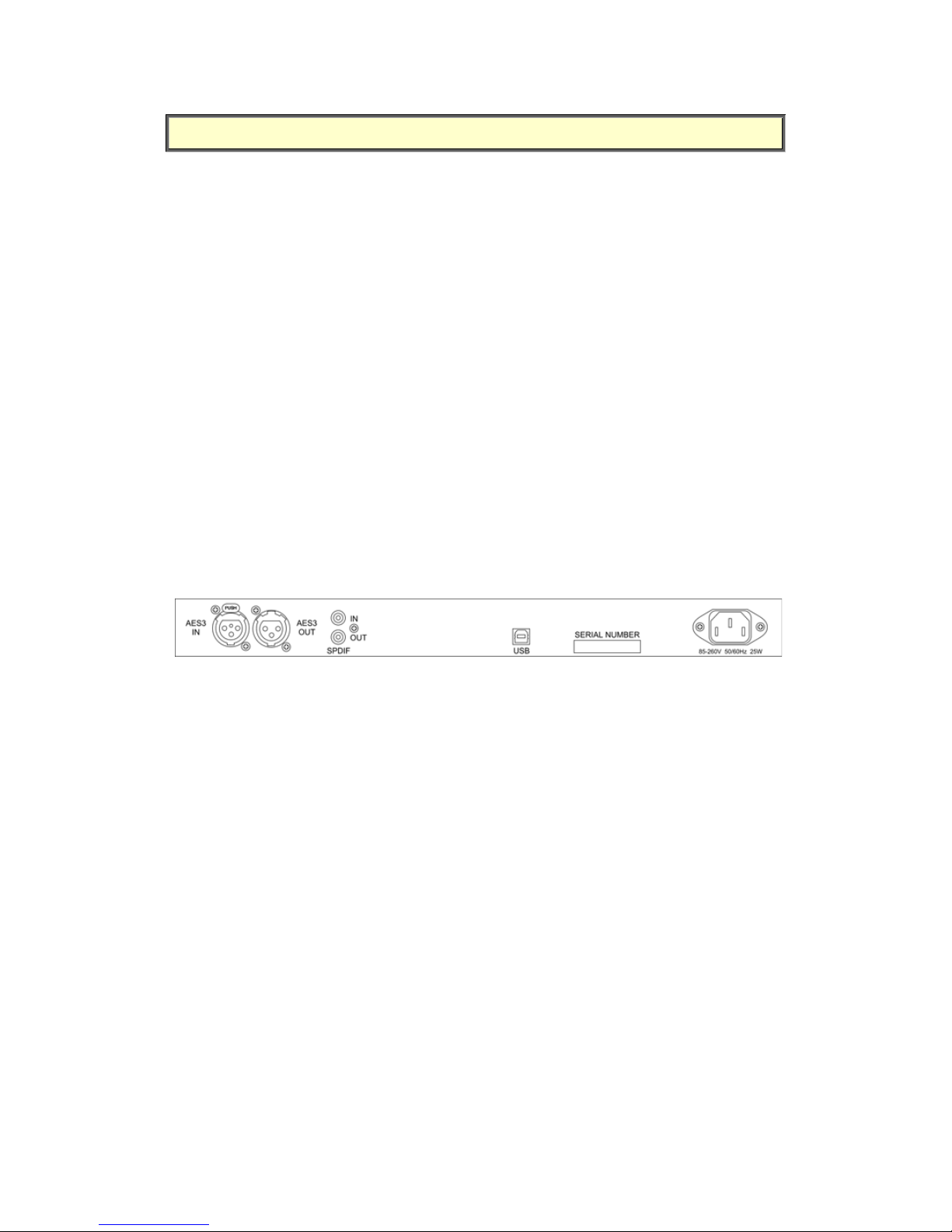
Rear Panel Connections
Audio
The DNS2000 offers two audio connection standards. It passes its signal to both outputs
irrespective of the input used. The standards are:
Digital SPDIF format
Digital AES/EBU format.
The processor will lock onto the first input that provides a valid clock. It is not affected by
channel status data and will echo any such data directly to the outputs.
USB
The USB connection allows you to control the DNS2000 hardware using your Pro Tools system.
You must connect the two using a USB cable.
Page 12
- 8 -
INSTALLING THE DNS CONTROL SYSTEM – MAC
Insert the CD.
Ensure that any older versions of the plug-in (if any) are archived and removed from the
plug-in folder.
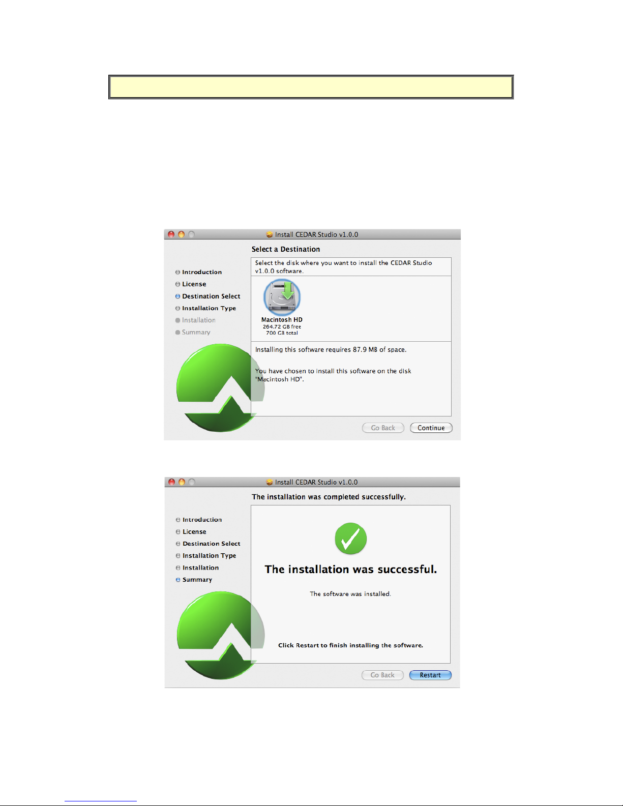
Double-click on the installer package:
CEDARStudioInstaller.mpkg
Follow the instructions offered by the installer.
Ensure that you have sufficient space on your drive.
Press the Continue button when prompted and the software will be installed. A message will
appear to tell you that the operation has been completed successfully.
Page 13
- 9 -
INSTALLING THE DNS CONTROL SYSTEM – PC
You will need to install two pieces of software: the Control System, plus a driver that allows the
PC to communicate with the DNS2000 hardware.
Insert the CD.
Double-click on the installer package:
setup.exe
Follow the instructions offered by the installer.
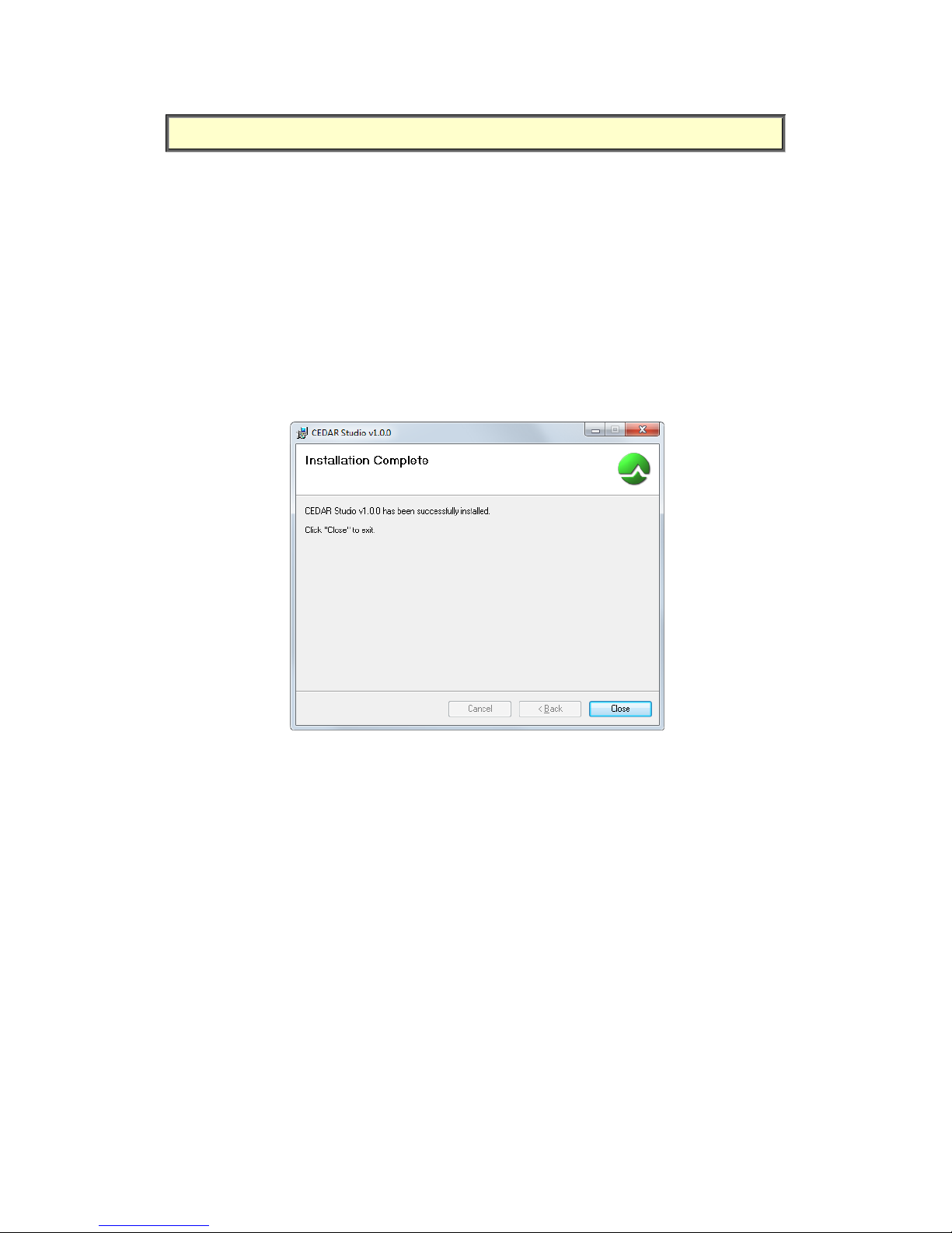
Press the Next button when prompted and the software will be installed. A message will
appear to tell you that the operation has been completed successfully.
When the installation is complete, click on Close.
DNS2000 driver:
Before connecting and using a DNS2000 for the first time on a given PC you will need to install
the hardware driver.
Locate the appropriate driver installation software in the \Win\Driver folder on the CD
that came with your DNS2000.
If you are running a 32-bit version of Windows run the file:
CEDARUSBInstaller_x86.exe
If you are running a 64-bit version of Windows run the file:
CEDARUSBInstaller_x64.exe
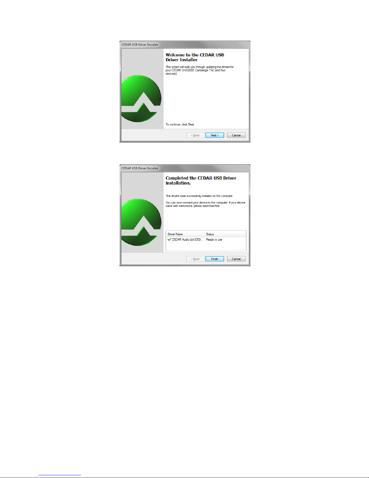
A wizard will guide you through the installation.
Page 14
- 10 -
When the wizard has completed installation, the following screen will appear to confirm that the
software has been successfully installed.
Page 15
- 11 -
Windows Security
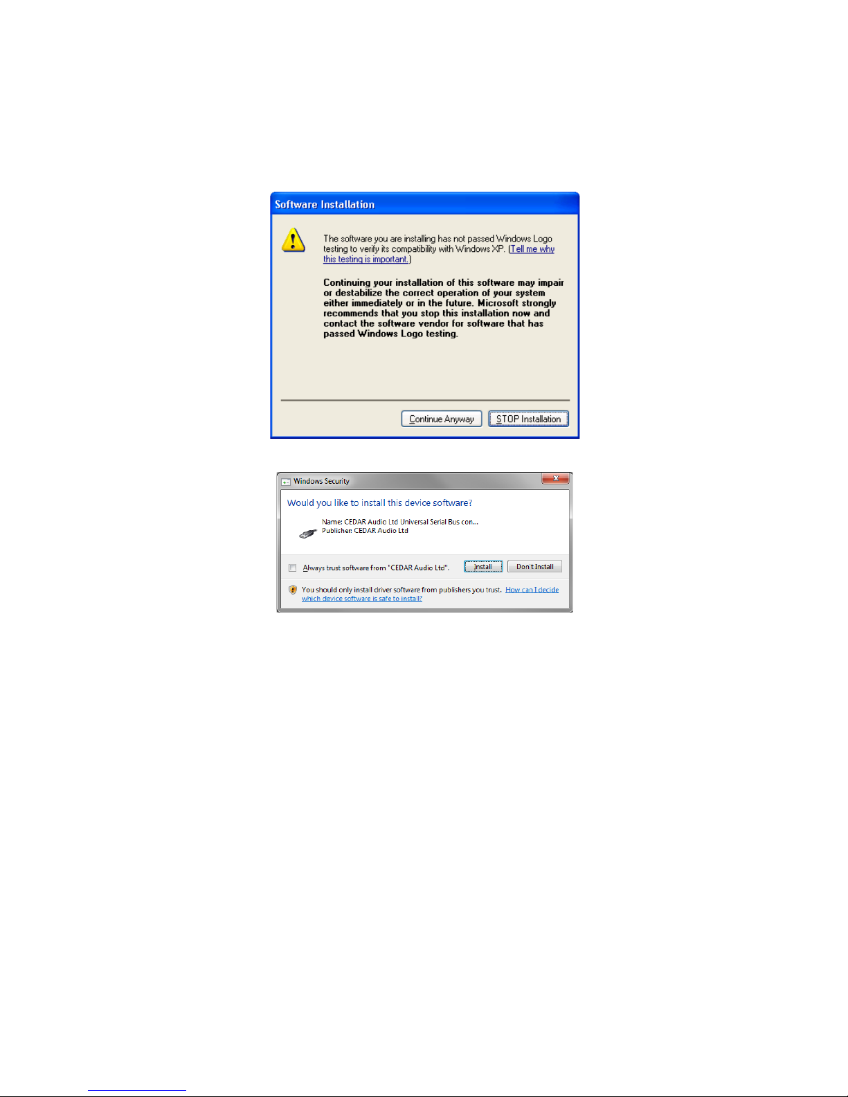
During the installation, the wizard will ask whether you trust software from CEDAR Audio Ltd.
(The exact message will differ according to which version of Windows you are running.)
Click on the appropriate button to proceed.
Windows XP security message
Windows 7 security message
Page 16
- 12 -
DNS CONTROL SYSTEM – CONTROLS
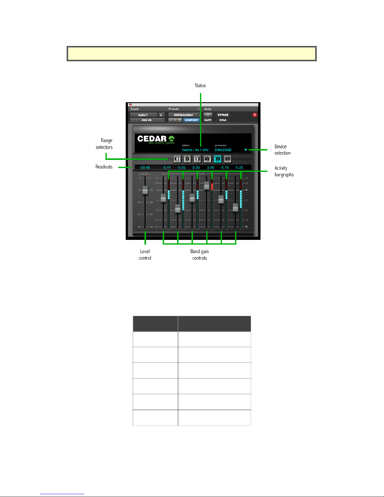
Range Selectors
The Range Selectors concentrate the unit’s activity into the desired part of the audio spectrum.
Selecting any of these ranges concentrates all of the filters within the DNS2000’s filter bank
across that part of the audio spectrum.
Level Control
The Level Control tells the DNS2000 how much noise is present in the input.
Range
Frequencies covered
Low
20Hz - 400Hz
Mid
200Hz - 6kHz
High
4kHz - 18kHz
Low+Mid
20Hz - 6kHz
Mid+High
200Hz - 18kHz
Full Range
20Hz - 18kHz
Page 17

- 13 -
Band Gain Controls
The DNS2000 divides a signal into a large number of well-defined bands. Sophisticated digital
filters analyse each of these bands and suppress the noise independently in each. The
innovative design of this filter bank allows you to adjust the DNS2000 using relatively few
controls.
The Band gain controls determine the maximum amount of processing that the DNS2000 will
apply in each band.
Activity Bargraphs
These offer a visual indication of the activity in each of the bands.
Device Selection
You can connect the DNS Control System to any of the following three CEDAR products:
DNS One
DNS2000
DNS3000
The drop-down list on the plug-in displays all the DNS processors that are currently available,
and it allows you to select which processing engine will be controlled by this instance of the DNS
Control System.
The DNS Network Scanner
If you have DNS3000s on the same network as the Pro Tools system
supporting your DNS2000, you can use the Scan Network option to detect
these and assign them for local use.
Status
If no processing engine is connected and/or selected, the I/O status will read No processor.
If the DNS Control System has successfully connected to a DNS2000 the following status
messages may occur:
Message
Explanation
XLR / 44.1kHz
If printed in blue, everything is working correctly. If in
orange, the sample rate is out of range.
RCA / 48.0kHz
If printed in blue, everything is working correctly. If in
orange, the sample rate is out of range.
---/-----
Unknown input status and unknown sample rate.
No lock
No valid audio signal has been detected at the input.
Page 18

- 14 -
If the DNS Control System has not connected successfully with the DNS2000 processing engine
the following status messages may occur:
Message
Explanation
No unit connected
No DNS2000 hardware has been detected.
Unknown error
Another error has occurred. Further investigation will be
required.
Generic Pro Tools Plug-in Controls
The standard Pro Tools plug-in facilities are provided. These have generic operation, and are
described in the Pro Tools documentation.
Automation
The Band Gain settings, the Level and the Range Selectors appear in the Plug-In Automation
screen and, together with the Pro Tools bypass control, may be automated in standard Pro Tools
fashion.
Page 19
- 15 -
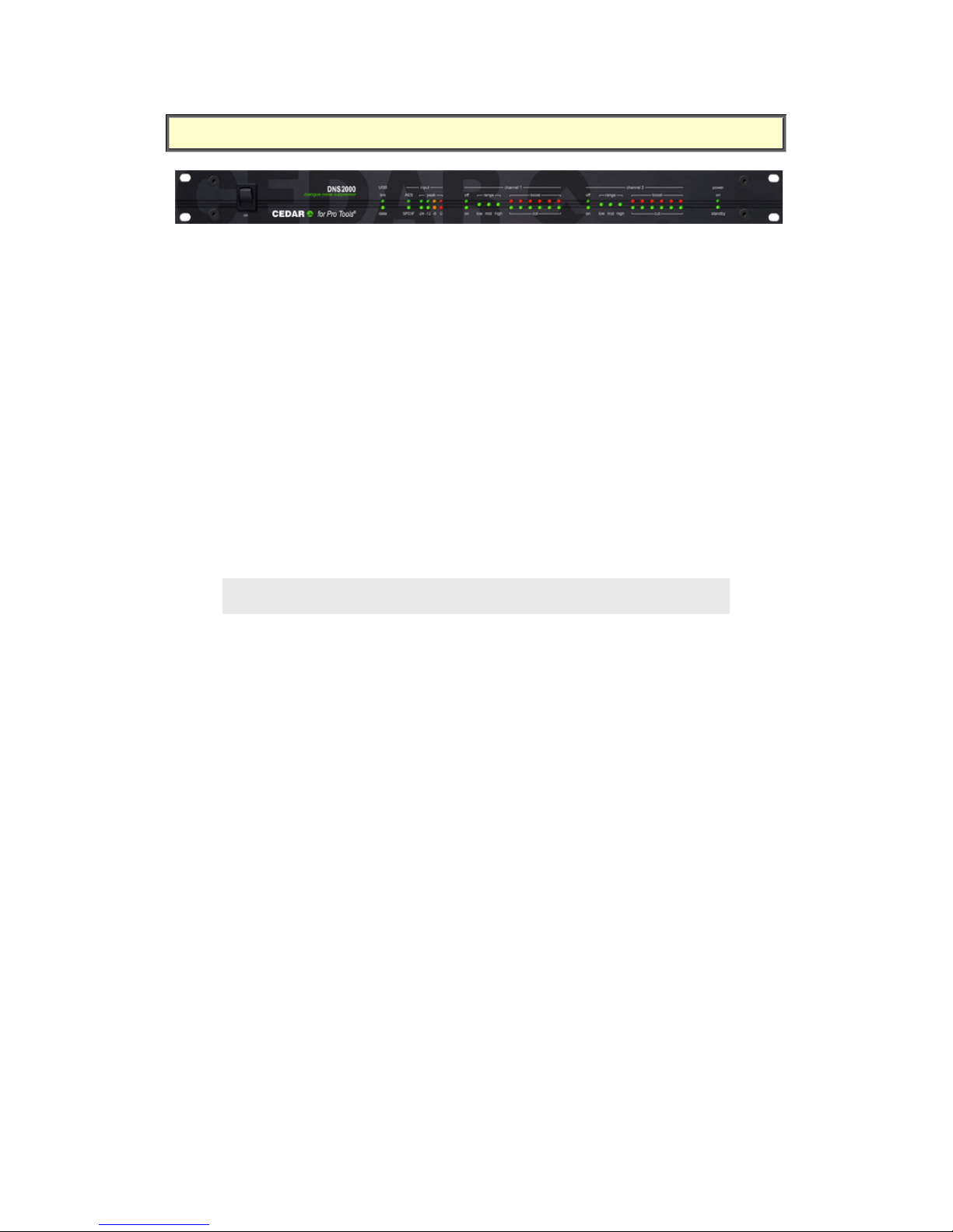
HARDWARE INDICATORS
USB LEDs
Link
When lit, this indicates a valid USB connection.
Data
This flashes when Pro Tools communicates with the DNS2000 via the USB input.
Input LEDs
AES, SPDIF
The lit LED indicates which audio input is in use. If the LEDs are flashing alternately, there is no
valid audio being presented to either of the DNS2000 processor’s inputs.
Peak
These LEDs indicate the audio input level. The upper row shows the level on Channel 1, the
lower row shows the level on Channel 2. If the red ‘0’ LED lights continuously for about one
second, this indicates input clipping.
The DNS2000 is capable of applying gain to the signal, so the absence of input
clipping does not guarantee the absence of output clipping.
Off / On LEDs - Channel 1 & Channel 2
These LEDs indicate whether the channel is selected to process.
Range LEDs - Channel 1 & Channel 2
The three LEDs Low, Mid and High indicate which range(s) is/are selected for processing.
Gain LEDs - Channel 1 & Channel 2
The twelve Activity LEDs for each channel offer a visual indication of the activity in each of the
six bands controlled by the Band Gain controls.
Both LEDs off: Less than ±0.5dB activity
Cut (green) LED dim: Between 0.5dB and 3dB attenuation
Cut (green) LED bright: Greater than 3dB attenuation
Boost (red) LED dim: Between 0.5dB and 3dB gain
Boost (red) LED bright: Greater than 3dB gain
Each band controls numerous filters. Therefore, the Activity LEDs for a given band display the
overall activity in that band, and are not necessarily indicative of the action of any single filter at
that moment.
Page 20
- 16 -
USE
Launch the DNS Control System, which is an RTAS plug-in, in the usual fashion. Remember that
the Control System software is precisely what it claims to be: a control system. It performs no
audio processing. To process an audio stream you must route it via the DNS2000 rackmount
unit. You can do this, for example, by using an insert point within the Pro Tools mixer.
Selecting a DNS2000 Processor
You can launch the DNS Control System (DNS CS) on your Pro Tools system, but until you tell it
which processor to use, it will do nothing.
The drop-down list on the DNS Control System displays any DNS2000 units plus all other
available processors (DNS One, DNS3000) connected to your system. If there is a DNS2000
serial number shown in the list, it is available for use on your system.
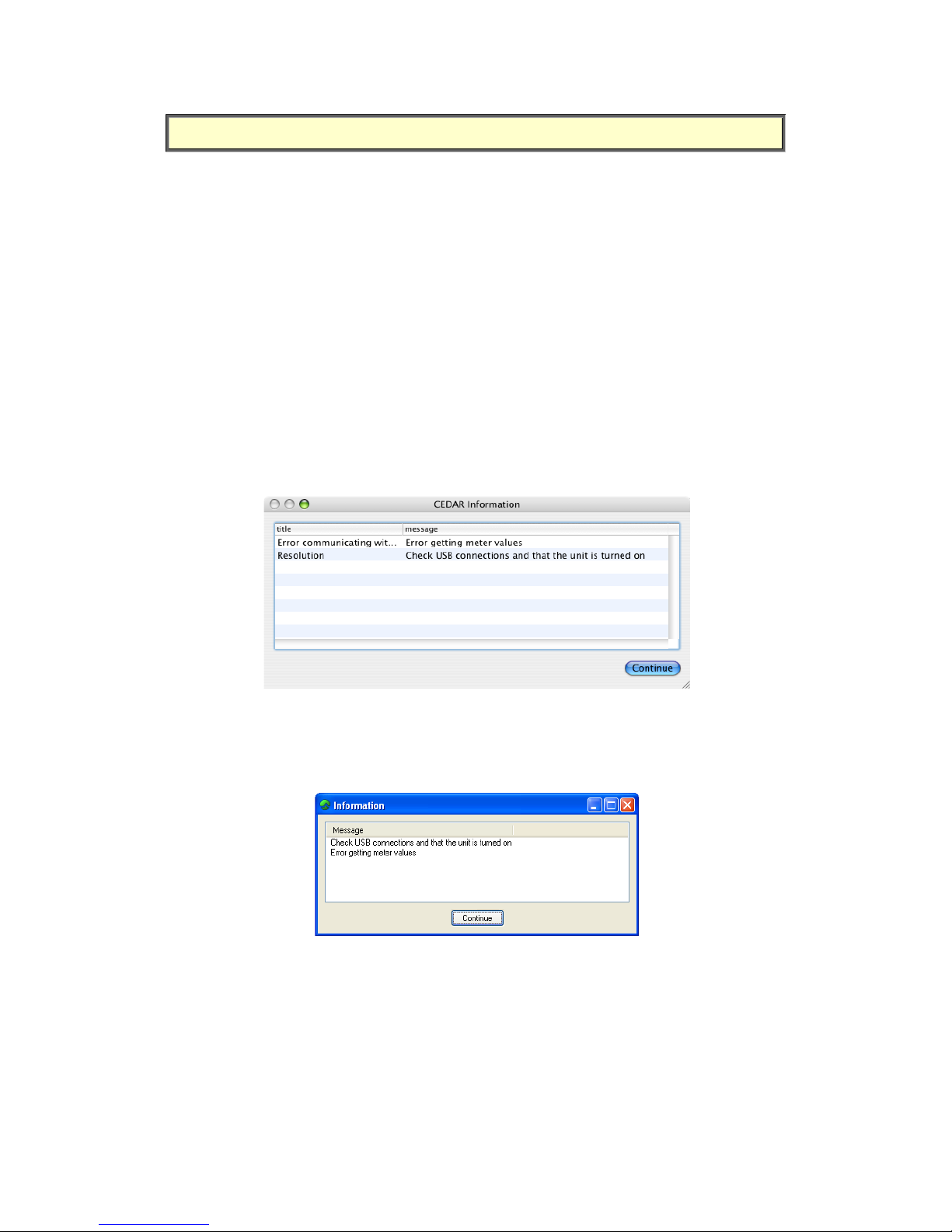
OS X users:
The following error message (or similar) indicates that - perhaps because of a power failure, or
because the USB connection has been severed - there is an error communicating with the
DNS2000 processor that you have requested.
PC Users:
The following error message (or similar) indicates that - perhaps because of a power failure, or
because the USB connection has been severed - there is an error communicating with the
DNS2000 processor that you have requested.
Range Selector
With a DNS2000 unit correctly connected and recognised by the Control System, you should
identify the frequency range or ranges in which the unwanted noise lies, and select any of six
possible processing ranges by clicking on the appropriate buttons.
With practise, you will be able to identify the range by ear. Until then, you may prefer to use the
methods described in the following case studies.
Page 21

- 17 -
Level Control
Your next job will be to identify the noise level of the audio. With the appropriate range
selected, pull all six Band Gain controls and the Level control down fully or use the
DNSQuickStart preset to do so. Now increase the Level slowly. At first, you will hear very little
happen but, at some point determined by the noise content of the recording, you will hear the
noise disappear. You should attempt to determine the point at which this occurs.
When the Band Gain controls are fully down, maximum processing occurs for
any given Level setting, thus making identification of the noise easier
Band Gain Controls
Once you have chosen the range and determined the Level, you control the action of the
DNS2000’s filter bank using the Band Gain controls.
The six faders represent six frequency bands (each containing multiple filters) distributed from
lower frequencies (left) to higher frequencies (right) across the selected range.
You will use the Band Gain controls to control the amount of noise attenuation performed in
each band, adjusting them to suppress as much noise as possible without introducing unwanted
artefacts into the desired signal.
Noise suppression occurs in a given band when the fader is below 0dB. However, there are
occasions when you might wish to boost the signal in a given band, and you can do this by
moving the appropriate fader above 0dB.
Creating generic settings files
If you save a Settings file in the Pro Tools Librarian menu window with ‘None’ selected as the
DNS processor, you can reload this file when connected to a given DNS and the control
parameters will be retrieved without changing the selection. The DNSQuickStart file is an
example of such a file, and can be used to initialise the control settings of any DNS.
If a DNS is specified when you save a Settings file, your system will attempt to reconnect to it
when you reload that file.
Tutorials
The following three tutorials illustrate ways to use the DNS2000. They may not be the ways that
you choose to operate it for all jobs, but they will get you started.
Page 22

- 18 -
SUPPRESSING TRAFFIC NOISE AND OTHER
AMBIENT SOUND
The DNS2000 can suppress background noises such as road traffic, aircraft, air conditioning,
wind, rain, and many other common soundstage, location, and outside broadcast (remote)
problems that contaminate audio. If your signal exhibits any of these problems, you can
suppress them as follows.
First, identify the frequency range(s) in which the noise lies.
You should be able to do this by listening to the problem. However, if this proves difficult, you
can use the following method.
It is not important that you find the perfect settings at the first attempt. In particular, you will
be able to refine your Level and Band Gain settings once you have found the correct range.
Begin as follows:
Ensure that the DNS 2000 is not in Bypass
Select Full Range
• Set all six Band Gain controls to -24dB
• Move the Level control to -80 and then raise it until the noise disappears
At this point you have determined an approximate setting for the Level. This is necessary for
determining the range but it is likely that you will refine this later in the procedure.
When the Level is close to the ideal setting, you should see the Activity Bargraphs in the Control
System flicker in response to the signal content.
Now continue as follows:
• Raise the Band Gain controls to 0dB (no processing occurs)
• Adjust the Band Gain controls to suppress the noise
You should always attempt to suppress the noise with the minimum of damage to the desired
signal.
In all likelihood, you will find that the leftmost Band Gain controls are pulled down significantly,
whereas the central and rightmost are close to 0dB. This tells you that the problem does not lie
in the upper frequencies, so you should use the Range Selectors to select Low+Mid. Then repeat
the steps marked ‘•’.
If you now find that you are using all six faders in similar fashion, it is likely that the noise is
distributed across the entire Low+Mid range. However, if the suppression is still heavily biased
towards the left-hand faders, you should now select the Low range and repeat the procedure.
If you select Low alone and cannot suppress the noise, it is probable that there is considerable
noise energy in the Mid band, so you should return to using Low+Mid ranges.
For many problems such as traffic noise, the noise will lie primarily in the range 50Hz - 1.5kHz.
In this case, Low+Mid will be the correct choice.
Second, optimise the Level control.
Listening carefully to the audio, refine the Level setting so that the noise is correctly identified
without introducing audible artefacts. If this proves difficult, you can return the Band Gain
controls to -24dB for this stage.
The DNS2000 takes a short period to settle after moving the Level control (especially in the
lower ranges) so you should not adjust it rapidly.
Page 23
- 19 -
Third, refine the Band Gain controls for optimum suppression.
Set all six Band Gain controls to 0dB. Now increase and decrease the gain in each band
separately while listening to the effect that each has on the noise. This will identify the bands
that contain the majority of the noise. (Do not be alarmed if all six bands contain significant
noise. This is not unusual.)
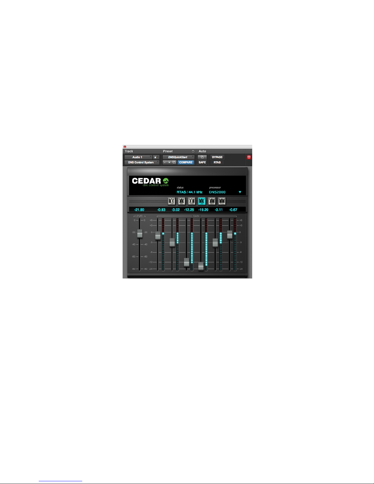
Let’s assume that the greatest improvement occurs when you reduce the gain in bands 3 and 4.
This suggests that the noise is concentrated in an approximate range of 200Hz to 1kHz. You
should now find the optimum positions for all six faders. The greatest cuts will lie in bands 3 and
4, whereas bands 1, 2, 5 and 6 should remain as close to 0dB as possible to ensure that
minimal signal damage occurs in the bands that do not contain much noise.
The final configuration might look like this:
Page 24
- 20 -
SUPPRESSING TAPE HISS
The DNS2000 can suppress the tape hiss that mars many older recordings. It will also improve
the signal/noise ratio of dialogue tapes that have been poorly copied as well as those that are
several generations old.
First, identify the frequency range(s) in which the noise lies.
You should follow the procedure laid down in the previous example to determine the range(s) in
which the problem lies. For most instances of tape hiss, you will find that the Mid+High ranges
are most appropriate. In a few cases you may find that the High range alone is most suitable.
It is not as common to require suppression in the Low range because hiss is usually less
prominent at lower frequencies, and it may also be masked by the genuine audio in the range.
Second, optimise the Level control.
To determine the correct Level, you should again follow the procedure described previously.
Third, refine the Band Gain controls for optimum suppression.
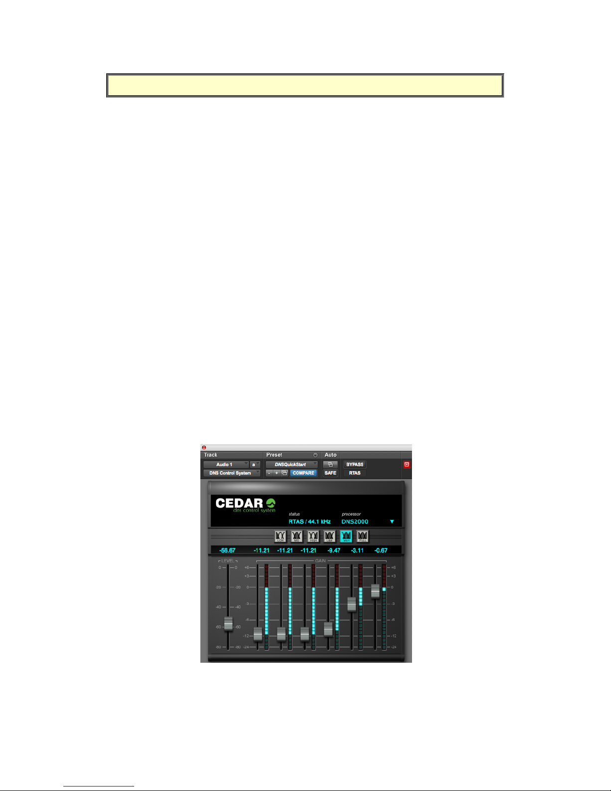
As in the first tutorial example, you should start with all six Band Gain controls at 0dB. You
should then increase and decrease each control individually to find the bands that contribute
most hiss to the signal. Because tape hiss often exhibits a white profile at Mid and High
frequencies, you may find that satisfactory results are achieved with the Band Gain controls set
in a horizontal line.
However, hiss is generally less annoying at very high audio frequencies. Consequently, you may
be able to reduce the amount of processing in the uppermost bands. This will help to ensure
that any low amplitude signal components lying at high frequencies (which provide much of the
‘air’, ‘ambience’ or ‘life’ in a signal) are passed with little or no attenuation.
The final configuration might look like this:
Page 25
- 21 -
SUPPRESSING EXCESSIVE REVERBERATION
In many situations, the DNS2000 can suppress excessive reverberation. This can be useful in TV
production when you need to match the audio from a large recording studio or soundstage to
visual images set in a small room or other enclosed space. Suppressing reverberation can also
be beneficial in increasing the intelligibility of poor dialogue recordings.
The method used to suppress reverberation is quite different from that applied in the previous
examples, and is as follows:
First, set the range in which the reverberation lies.
In general, reverberant spaces include soft materials that absorb high frequencies more rapidly
than middle and lower frequencies. Even bare rooms with hard walls include these soft
materials: they are the people who are speaking.
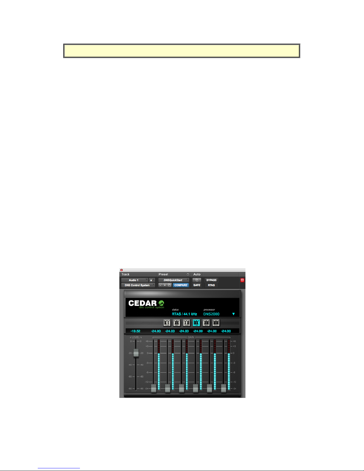
Consequently, you will find that Low+Mid is almost always the most appropriate combination of
ranges for suppressing reverberation.
Second, set the Band Gain controls.
You should set all six Band Gain controls to -24dB. This will ensure that (if the Level is set
correctly) the DNS2000 applies maximum suppression to the tails of the sound.
Third, optimise the Level control.
Starting at its minimum position (-80dB) increase the Level control slowly. At some point before
full noise suppression becomes apparent, you will hear the tails of louder sounds become
truncated.
You can adjust the amount of truncation of the reverb using the Level control rather than the
Band Gain controls.
The final configuration might look like this:
Page 26

- 22 -
SPECIFICATIONS
General
Power supply: 85–260VAC; 50–60Hz
Dimensions: 1U rackmount, 20cm depth
Audio
I/O type: Digital PCM Sample rates: 44.1, 48 kHz
I/O resolution: 24 bits Data formats: SPDIF or AES/EBU
Processor power: 198MFLOPS Process resolution: 40 bits
Latency: <10 samples
Page 27

- 23 -
EMC REGULATIONS
In order to comply with EMC regulations, you must connect the DNS2000 using metal-shelled
connectors and good quality shielded cable suitable for digital audio.
Declaration of conformity
Date of issue: 1 April 2002
Equipment: CEDAR DNS2000
Manufacturer: CEDAR Audio Ltd
Address: 20 Home End, Fulbourn, Cambridge CB21 5BS, UK
This is to certify that the aforementioned equipment, when used in accordance with the
instructions in this manual, fully conforms to the protection requirements of the following EC
Council Directives: on the approximation of the laws of the member states relating to:
89/336/EEC Electromagnetic Compatibility
Applicable standards: EN 55103-1:1996 EN 55103-2:1996
73/23/EEC Low Voltage Equipment
Applicable standard: EN 60065:1998
E&OE. The Company reserves the right to change specifications without notice.
Page 28

- 24 -
LICENCE AND LIMITED WARRANTY
1. DEFINITIONS
In this Licence and Limited Warranty the following words and phrases shall bear the following meanings:
‘the Company’ is CEDAR Audio Limited of 20 Home End, Fulbourn, Cambridge CB21 5BS, UK;
‘the System’ means an instance of the DNS2000 sound-reprocessing system comprising hardware and
software held on non-volatile memory (‘firmware’) developed by the Company;
‘this Document’ means this Licence and Limited Warranty.
2. ISSUE AND USE OF THE SYSTEM
2.1 The terms and conditions of this Document are implicitly accepted by any person or body corporate who
shall at any time use or have access to the System, and are effective from the date of supply of the System
by CEDAR Audio Limited to its immediate customer.
2.2 The Company hereby grants to the Licensee and the Licensee agrees to accept a non-exclusive right to
use the System.
3. PROPERTY AND CONFIDENTIALITY
3.1 The System contains confidential information of the Company and all copyright, trade marks, trade
names, styles and logos and other intellectual property rights in the System including all documentation and
manuals relating thereto are the exclusive property of the Company. The Licensee acknowledges that all such
rights are the property of the Company and shall not question or dispute the ownership of any such rights
nor use or adopt any trading name or style similar to that of the Company.
3.2 The Licensee shall not attempt to reverse engineer, modify, copy, merge or transcribe the whole or any
part of the System or any information or documentation relating thereto.
3.3 The Licensee shall take all reasonable steps to protect the confidential information and intellectual
property rights of the Company.
4. LIMITED WARRANTY AND POST-WARRANTY OBLIGATIONS
4.1 The Company warrants that the System will perform substantially in accordance with the appropriate
section of its accompanying product manual for a period of one year from the date of supply to the
Company’s immediate customers.
4.2 The Company will make good at its own expenses by repair or replacement any defect or failure that
develops in the System within one year of supply to the Company’s immediate customer.
4.3 The Company shall have no liability to remedy any defect, failure, error or malfunction that arises as a
result of any improper use, operation or neglect of the System, or any attempt to repair or modify the
System by any person other than the Company or a person appointed with the Company’s prior written
consent.
4.4 In the case of any defect or failure in the System occurring more than twelve months after its supply to
the Company’s immediate customer the Company will at its option and for a reasonable fee make good such
defect or failure by repair or replacement (at the option of the Company) subject to the faulty equipment
having first been returned to the Company. The Company will use reasonable efforts to return repaired or
replacement items promptly, all shipping, handling and insurance costs being for the account of the Licensee.
4.5 The above undertakings 4.1 to 4.4 are accepted by the Licensee in lieu of any other legal remedy in
respect of any defect or failure occurring during the said period and of any other obligations or warranties
expressed or implied including but not limited to the implied warranties of saleability and fitness for a specific
purpose.
4.6 The Licensee hereby acknowledges and accepts that nothing in this Document shall impose upon the
Company any obligation to repair or replace any item after a time when it is no longer produced or offered
for supply by the Company or which the Company certifies has been superseded by a later version or has
become obsolete.
5. FORCE MAJEURE
The Company shall not be liable for any breach of its obligations hereunder resulting from causes beyond its
reasonable control including, but not limited to, fires, strikes (of its own or other employees), insurrection or
Page 29

- 25 -
riots, embargoes, container shortages, wrecks or delays in transportation, inability to obtain supplies and raw
materials, or requirements or regulations of any civil or military authority.
6. WAIVER
The waiver by either party of a breach of the provisions hereof by the other shall not be construed as a
waiver of any succeeding breach of the same or other provisions, nor shall any delay or omission on the part
of either party to exercise any right that it may have under this Licence operate as a waiver of any breach or
default by the other party.
7. NOTICES
Any notices or instruction to be given hereunder shall be delivered or sent by first-class post or telecopier to
the other party, and shall be deemed to have been served (if delivered) at the time of delivery or (if sent by
post) upon the expiration of seven days after posting or (if sent by telecopier) upon the expiration of twelve
hours after transmission.
8. ASSIGNMENT AND SUB-LICENSING
The Licensee may at his discretion assign the System and in doing so shall assign this Licence its rights and
obligations to the purchaser who shall without reservation agree to be bound by this Licence. The original
Licensee and any subsequent Licensees shall be bound by the obligations of this Licence in perpetuity.
9. LIMITATION OF LIABILITY
The Company’s maximum liability under any claim including any claim in respect of infringement of the
intellectual property rights of any third party shall be, at the option of the Company either:
(a) return of a sum calculated as the price received for the System by the Company from its immediate
customer depreciated on a straight line basis over a one year write-off period; or
(b) repair or replacement of those components of the System that do not meet the warranties contained
within this Document.
The foregoing states the entire liability of the Company to the Licensee.
10. CONSEQUENTIAL LOSS
Even if the Company has been advised of the possibility of such damages, and notwithstanding anything else
contained herein the Company shall under no event be liable to the Licensee or to any other persons for loss
of profits or contracts or damage (whether direct or consequential) arising in connection with the System or
any modification, variation or enhancement thereof and including any documentation or data provided by the
Company or for any other indirect or consequential loss.
11. ENTIRE AGREEMENT
The Company shall not be liable to the Licensee for any loss arising in connection with any representations,
agreements, statements or undertakings made prior to the date of supply of the System to the Licensee.
12. TERMINATION
This Licence may be terminated forthwith by the Company if the Licensee commits any material breach of
any terms of this Licence. Forthwith upon such termination the Company shall have immediate right of
access to the System for the purpose of removing it.
13. SEVERABILITY
Notwithstanding that the whole or any part of any provision of this Document may prove to be illegal or
unenforceable the other provisions of this Document and the remainder of the provision in question shall
remain in full force and effect.
14. HEADINGS
The headings to the Clauses are for ease of reference only and shall not affect the interpretation or
construction of this Document.
15. LAW
This Document shall be governed by and construed in accordance with English law and all disputes between
the parties shall be determined in England in accordance with the Arbitration Act 1950 and 1979.
Page 30

DNS2000
CEDAR Audio Limited
20 Home End
Fulbourn
Cambridge
CB21 5BS
United Kingdom
t: +44 1223 881771
w: www.cedaraudio.com
Copyright CEDAR Audio Ltd, © 2011
CEDAR is a registered trademark of CEDAR Audio Ltd
DNS One, DNS1000, DNS1500, DNS2000 and DNS3000 are trademarks of CEDAR Audio Ltd
E&OE, subject to revision at the Company’s sole discretion
 Loading...