

Page 1
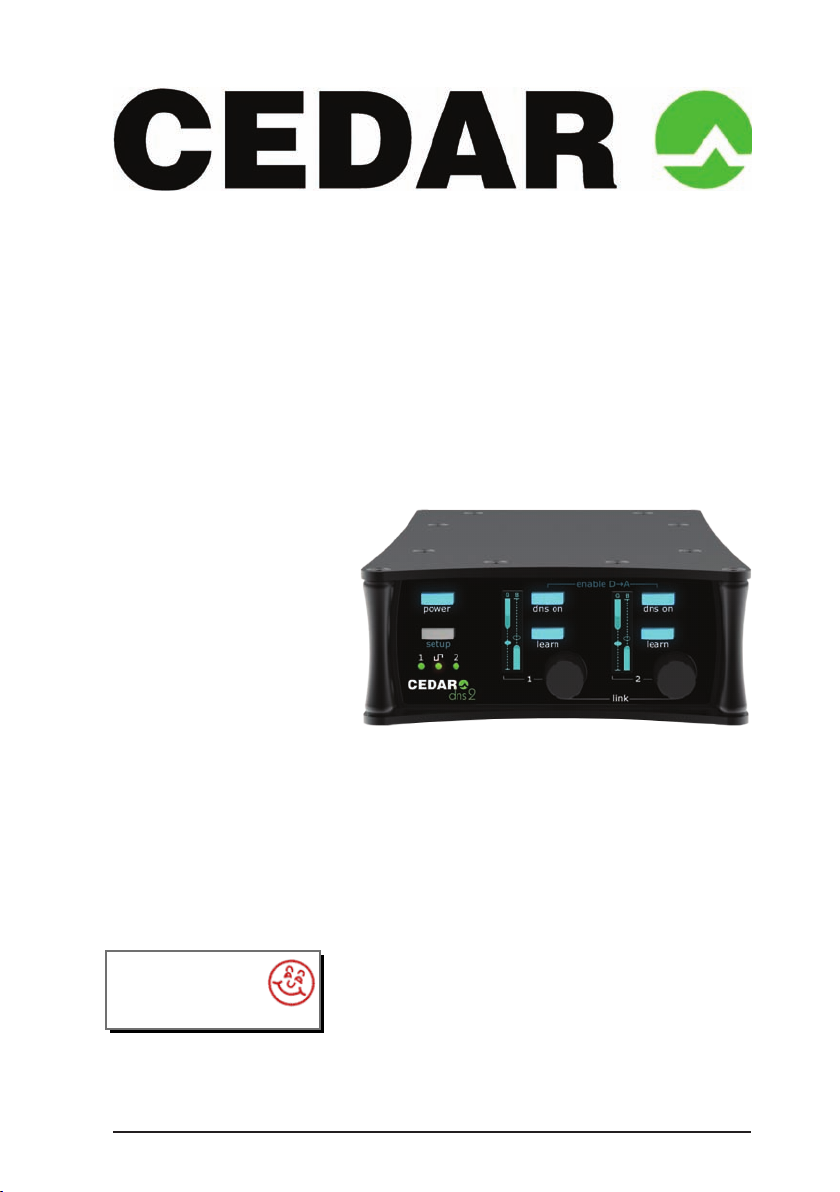
DNS 2 dialogue noise suppressor
interstage
Phistersvej 31, 2900 Hellerup, Danmark
Telefon 3946 0000, fax 3946 0040
www.interstage.dk
- pro audio with a smile
OWNER’S MANUAL
© 2016 CEDAR Audio Ltd
Manual version 1.05: October 2016
Page 1
Page 2

Page 2
This page left blank
Page 3

Page 3
English
Page 4

Page 4
AN INTRODUCTION TO THE DNS 2
The DNS 2 is a further development of the DNS technology introduced in
the Academy Award winning DNS1000 and the DNS 8 Live dialogue noise
suppressors. It is small, light and portable, and ideal for use on location as well
as in the studio and in post. Offering two channels of dialogue noise suppression,
its simple user-interface allows users to obtain optimum results almost instantly
and with the minimum of effort. Nonetheless, it retains the near-zero latency of its
predecessors and, with its 4-pin 12VDC power socket, it’s suitable for use in all
live situations - not just on location and for live-to-air broadcasting, but also for live
sound in venues such as theatres, concert halls, conferences venues, and places
of worship.
The DNS 2 operates by dividing incoming signals into a large number of
bands. Sophisticated lters analyse each of these and then suppress the noise
independently in each. The innovative design of the lter bank eliminates the
need to select the range of frequencies in which the unit will operate, and it’s not
necessary to adjust the amount of attenuation in individual bands.
Features:
■ Near zero latency
A group delay of less than 1ms, so there is no loss of lip-sync.
■ Flexibility
The ability to handle a wide range of noise suppression requirements.
■ Speed and ease of use
A carefully designed user-interface that maximises speed of use.
■ Audio interfaces
24-bit digital audio interfaces conforming to AES/EBU standards plus highquality analog mic/line inputs with optional +48V phantom power.
■ 12VDC power
The ability to work anywhere in the world.
■ Powerful processors
The latest high resolution oating-point processors to ensure that it handles
the most complex processing requirements.
Page 5

Page 5
SAFETY INSTRUCTIONS
Read these instructions, and follow them.
■ Water and moisture
The DNS 2 and its power adapter must not be exposed directly to rain or
moisture. Furthermore, if it is brought directly from a cold environment into a
warm one, moisture may condense inside it. Allow the equipment to reach
ambient temperatures naturally before connecting the power.
■ Mounting and ventilation
Do not subject the equipment to strong sunlight, excessive dust,
mechanical vibration or periodic shocks. It is not susceptible to excessive
heat build-up, but should be installed away from heat sources such as
radiators and audio devices that produce large amounts of heat.
■ Connections
Turn off the power to all equipment before making connections.
■ Cleaning
Clean the equipment only with a dry cloth. Never use abrasive pads or
liquid cleaners such as alcohol or benzene.
■ Damage requiring service
The equipment contains no user-serviceable parts and should on no
account be opened or dismantled by unauthorised personnel.
The equipment should be returned to qualied service agents when it has
been exposed to liquids, when it fails to function correctly, when it has
been dropped, or when the case is damaged.
Page 6

Page 6
OPERATION
Unpack the DNS 2 carefully. Save the carton and all packing materials since you
may need them in the future. In addition to the DNS 2, the box should contain:
■
12V DC power supply
■
start-up and safety instructions sheet
■
warranty registration card
To maintain reliability and prolong operating life, observe the following
environmental considerations:
■
the temperature should be maintained between 5º and 30º Celsius
■
relative humidity should be in the range 30% to 80% non-condensing
■
strong magnetic elds should not exist nearby.
Power sources
Power is supplied by an external DC source of 8–17.5V with a lm industry 4-pin
XLR. A 12V PSU is included with the unit and this will work on any mains supply in
the range 85V to 250V, 50/60Hz AC. Connect its output to the DNS 2 power input
and then plug it into the mains supply.
Press the power on/off button to switch power on and off:
■
press the button briey to switch the power ON
■
hold the button for a couple of seconds to switch the power OFF
Controls
Each channel has its own process controls and indicators. These comprise two
illuminated push buttons, a rotary encoder with an integrated push switch, and a
small dot-matrix display. These are used for both setup and process control.
Connections
The DNS 2 offers analog and digital audio connections. It can pass its signal to
both outputs irrespective of the input used.
Select the active audio input using the two-position toggle switch on the side of the
unit. When the analog inputs are in use, a three-position switch for each channel
selects between line, microphone and microphone with +48V phantom powering.
Analog input
Set the input selector switch to ANALOG IN (switch to left).
Connect microphones or line level signals to the analog input XLRs. Select LINE,
MIC, or 48V (MIC with 48V phantom power) for each input as appropriate. Connect
the analog and/or digital XLR outputs to suitable inputs on your recording or
monitoring equipment.
Page 7

Page 7
Internal Sync
When the analog inputs are selected, sychronisation is derived by default from a
xed internal 48kHz clock, and the digital output clock is derived from this internal
clock.
External Sync
To use the analog to digital conversion of the DNS 2 at a sample rate other than
48kHz, or to lock its digital outputs to house sync, connect an AES3 or AES11 sync
signal to the digital input. The front panel sync LED will show green, and the DNS 2
will automatically synchronise to the external signal. Operation at 44.1kHz, 48kHz
and 96kHz is supported.
Gain
Press the SETUP button to monitor the input signal level on the displays. If desired,
you can use the encoders to adjust the gain of the analog input for each channel.
Press the SETUP button again to return to the process control page.The operations
of the controls and displays will also revert to process control page after a short
idle period.
Digital input
Set the input selector switch to DIGITAL IN (switch to right) and connect an AES
digital source to the digital input XLR. Connect the digital and/or analog output
XLRs to suitable inputs on your recording or monitoring equipment.
The unit will lock to any AES3 signal with a sample rate of up to 96kHz that is
presented to its inputs. Operation is supported at 44.1kHz, 48kHz and 96kHz.
Sync
If the input selection switch is set to digital and no valid digital signal is present
at the digital input, the SYNC LED will light up red and the DNS 2 will not process
audio.
Enabling the analog outputs
The analog I/O accounts for about one third of the DNS 2’s power consumption. To
save power, it will shut down when the digital input is selected, resulting in digitalto-digital operation.
To use the DNS 2 “digital IN, analog OUT”, you can re-enable the analog outputs
by pressing SETUP to enter the setup page and then pressing both DNS ON
buttons simultaneously. Repeat this operation to switch the analog outputs off
again.
USB
There is a USB socket for updating the rmware.
Page 8

Page 8
Processing
Process On/Off
Use the DNS ON buttons to switch the DNS process on and off for each channel.
Learn
The LEARN buttons control whether or not the noise detector adapts continuously
to the noise in the audio signal; switching it off freezes the noise estimate until it is
switched on again. LEARN is not a method for taking a ‘noise ngerprint’ and, for
most jobs, best results are obtained by leaving it switched on permanently.
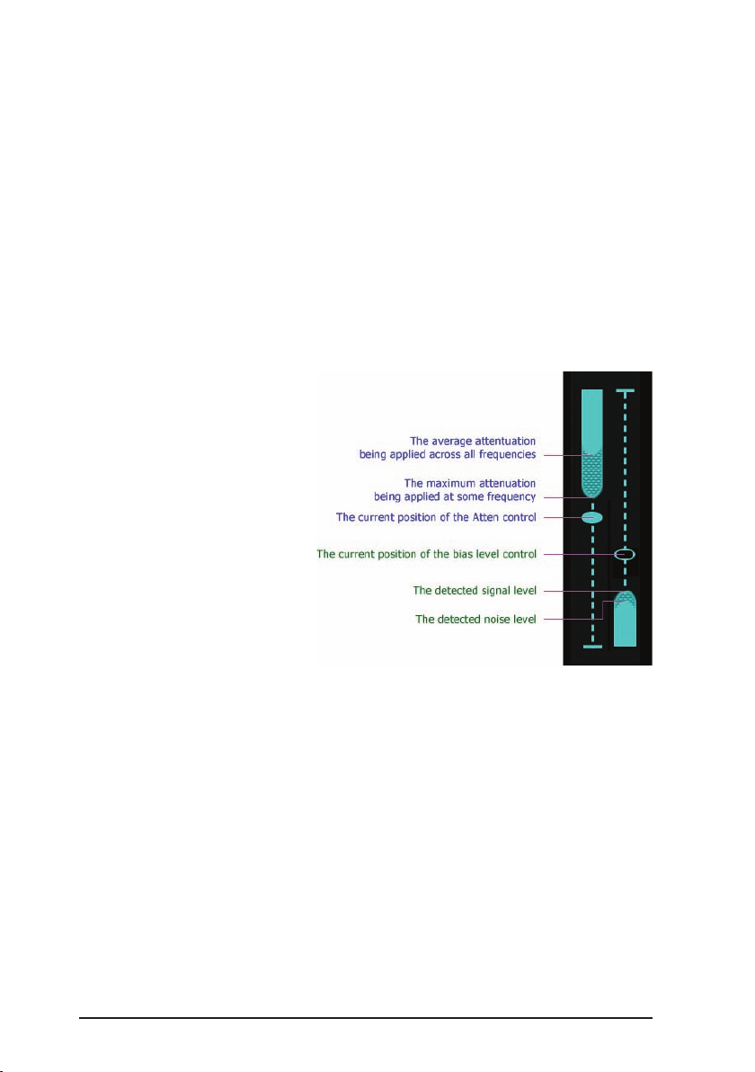
Attenuation
The default action of each encoder is to adjust the amount of noise attenuation
applied to the signal, and this is shown on the left-hand half of the display. The
representation of the fader within the display shows the current position of the
control, and the bargraph shows the instantaneous amount of attenuation being
applied to the signal. The solid bar shows the average attenuation across all
frequencies, and the shaded bar shows the maximum attenuation across all
frequencies.
Bias
The encoder also provides control of the Bias, which is shown on the right-hand
half of the display. Click an encoder to enable adjustment of the Bias, and click it
again when you wish to switch back to controlling the Attenuation. The encoders
will also revert to controlling the Attenuation after a short idle period.
The Bias is a ‘center-zero’ control, and the fader shows the current position. Raise
the Bias to increase the amount of noise detected. This will allow the process to
remove more noise, but may lead to compression of the wanted audio and make
the signal sound dry. Lower the Bias to decrease the amount of noise detected.
This will allow the process to retain more ‘atmos’, but it will remove less noise.
The right-hand bargraph shows the detected long-term signal to noise ratio (SNR).
The solid bar shows the detected noise level, and the shaded bar shows the
detected long-term signal level; consequently, the difference between the heights
of the solid and shaded bars indicates the long-term SNR. When the Bias is above
or below center, it biasses the noise detector somewhat upwards or downwards.
You can see this effect reected in the height of the solid bar, which tends to
increase as you raise the Bias (and vice-versa).
Linking
The two channels of the DNS2 can operate in three different link modes. You can
cycle through these by pressing both encoders simultaneously.
Unlinked: The two channels of the DNS2 operate completely independently. This
mode is useful for processing two separate sources, for example a boom mic and
a radio mic.
Page 9

Page 9
Linked: The audio channels remain separate, but their control settings are linked
together. This mode is particularly suitable for stereo signals. (When using analog
inputs, the input gains are linked if both are set to mic or both are set to line, but if
one input is set to mic and the other to line then the input gains are not linked.)
Mono split: Input channel 1 is split and sent to both process channels and
outputs. The channel 2 input signal is not used in this mode. The process channels
have independent controls, so this allows a single input signal to be processed in
two different ways, or (by switching off the processing of one channel) for the two
outputs to be processed and unprocessed versions of the channel 1 input signal.
The input selection and link mode are indicated at the bottom of the process
channel displays. Linked mode is indicated by an ‘=’ symbol, and mono split
mode is indicated by an ‘>’ symbol. The input selection is indicated by M/L/D for
microphone, line or digital respectively, followed by a 1 or 2 to indicate the input
channel number. Hence, in mono split mode both screens show channel 1.
Other information
Panel lock
A toggle switch on the side of the DNS 2 disables all of the front panel controls
with the exception of the power button, which can still perform its power on
function. In general use, switch this to OFF (switch in upper position). Switch it ON
to prevent accidental adjustment of the front panel controls.
Screensaver
The intensities of the displays and front panel LEDs will drop after a period of
inactivity. Touching any control will bring the brightnesses back to normal.
Signal level LEDs
Bi-colour LEDs indicate the signal level for each channel:
■
Off = silence
■
Green = normal
■
Red = close to clipping
Synchronisation LED
The sync LED indicates the current sync source as shown in the following table:
Input switch Digital input lock Sync status Sync source Audio source Sync LED
Analog No Normal Internal Analog Off
Digital No Error Internal Mute Red
Analog Yes Normal External Analog Green
Digital Yes Normal External Digital Green
Page 10
Page 10
Storage of settings
The DNS 2’s current settings are stored every time the buttons and screens go
dim, which happens a few seconds after the user stops adjusting the controls.
These settings are recalled when the DNS2 is turned on.
Power On/Off
Switch the DNS 2 on and off using the power button. Units from serial number
DNS-2-11017 onward power up automatically when external power is rst applied.
If a problem occurs, you can switch the unit off by pressing the power on/off button
for ve seconds or more to perform a ‘hard’ power off.
Summary of operation
LEARN
When LEARN is on, the DNS 2
continually identies the power
and spectral distribution of
the noise present. This is the
normal mode of operation.
When LEARN is off, the noise
identication is frozen at the
last determined values.
Bias
Adjusts the amount of noise
detected by LEARN. You can
bias the detection upward
(more noise detected)
or downward (less noise
detected).
Attenuation
Determines how much noise will be removed from the signal.
Summary
LEARN and Bias determine what is detected as noise.
Attenuation determines how much of the detected noise is suppressed.
Page 11

Page 11
Deutsch
Page 12

Page 12
EINFÜHRUNG IN DEN DNS 2
Der DNS 2 ist eine weitere Entwicklung der DNS (Dialogue Noise Suppressor)
Technologie, die mit dem Academy Award - ausgezeichneten DNS1000 und
dem DNS 8 Live eingeführt wurde. Er ist klein, leicht und portabel – ideal für
den Einsatz am Produktionsort wie auch im Studio oder in der Postproduktion.
Die einfache Bedienung der zwei Kanäle liefert optimale Ergebnisse unmittelbar
und mit geringstem Aufwand. Mit einer Latenz nahe Null und 4-pol 12VDC
Netzanschluss ist er für alle Livesituationen geeignet – nicht nur am Set oder bei
Rundfunkübertragungen aber auch in Theatern, Konzert- und Konferenzhallen oder
Kirchen.
Der DNS 2 teilt das ankommende Signal in eine hohe Anzahl von Bändern.
Komplexe Filter analysieren jedes und reduzieren das Geräusch individuell in
jedem Band. Das innovative Design der Filter Bank eliminiert die Notwendigkeit
einen Frequenzbereich auszuwählen, in dem das Gerät arbeitet. Es ist ebenso
nicht nötig den Grad der Dämpfung in den einzelnen Bändern einzustellen.
Funktionen:
■ Nahe Null Latenz
Das Signal bleibt lippensynchron dank einer Gruppenlaufzeit von weniger
als 1ms
■ Flexibilität
Die Fähigkeit verschiedenste Anforderungen an Geräuschunterdrückung zu
erfüllen.
■ Geschwindigkeit und Einfachheit der Bedienung
Eine sorgfältig gestaltete Bedienoberäche, für maximale
Arbeitsgeschwindigkeit.
■ Audioschnittstellen
24-bit Digital-Audioschnittstellen im AES/EBU Standard und hochwertige
analoge Mic/Line Eingänge mit zuschaltbarer +48V Phantomspeisung.
■ 12VDC Stromversorgung
Die Möglichkeit überall in der Welt zu arbeiten.
■ Leistungsstarke Prozessoren
Neueste, hochauösende Floating-Point-Prozessoren für die komplexesten
Anforderungen an die Signalverarbeitung.
Page 13

Page 13
SICHERHEITSANWEISUNGEN
Bitte lesen und befolgen Sie die folgenden Sicherheitsanweisungen.
■ Wasser und Feuchtigkeit
Der DNS 2 und der Netzadapter dürfen nicht Regen oder Feuchtigkeit
ausgesetzt werden. Darüber hinaus kann Feuchtigkeit im Geräteinnern
kondensieren, wenn das Gerät vom Kalten ins Warme gebracht wird.
Ermöglichen Sie, dass das die Geräte auf natürlichem Wege die
Umgebungstemperatur erreichen, bevor Sie die Stromversorgung
anschließen.
■ Montage und Luftzirkulation
Setzen Sie das Gerät keinem starken Sonnenlicht, starkem Staub oder
mechanischer Erschütterung aus. Es ist nicht für starke Hitzebildung
anfällig aber sollte weg von Hitzequellen wir Heizungen oder
hitzeentwickelnden Audiogeräten verwendet werden.
■ Verbindungen
Schalten Sie das gesamte Equipment aus, bevor sie Verbindungen
herstellen.
■ Reinigung
Verwenden Sie lediglich ein trockenes Tuch zur Reinigung. Verwenden Sie
niemals Scheuermittel oder Lösungsmittel.
■ Reparaturen
Die Geräte enthalten keine Teile, die vom Benutzer repariert werden
können und dürfen nicht von unauthorisierten Personen geöffnet werden.
Die Geräte sollen zu qualizierten Servicestellen gesendet werden, falls sie
feucht geworden sind, nicht mehr korrekt funktionieren, heruntergefallen
sind oder wenn das Gehäuse beschädigt wurde.
Page 14

Page 14
BEDIENUNG
Packen Sie den DNS 2 vorsichtig aus und bewahren Sie die Verpackung für den
Fall auf, dass Sie sie später noch einmal benötigen. Neben dem DNS 2 sollten sich
folgende Teile in der Verpackung benden:
■
12V DC Netzteil
■
start-up & safety instructions sheet
■
warranty registration card
Um die Zuverlässigkeit und eine lange Lebensdauer zu gewährleisten, sollten die
folgenden Umstände eingehalten werden:
■
Temperatur zwischen 5º und 30º Celsius
■
Relative Luftfeuchtigkeit zwischen 30% und 80%, nicht kondensierend
■
Keine starken magnetische Felder in der Nähe
Netzversorgung
Als Netzteil dient eine externe 8-17,5 V Gleichspannungsversorgung,
angeschlossen mit einem üblichen 4-pin XLR Stecker. Ein 12V Netzteil für
den Betrieb an 85V bis 250V, 50/60Hz AC Stromnetzen ist im Lieferumfang
enthalten. Verbinden Sie den Ausgang des Netzteils mit dem DNS 2
Stromversorgungseingang und stecken Sie es in die entsprechende
Netzsteckdose.
Drücken Sie die power on/off Taste, um das Gerät ein- oder auszuschalten:
■
Zum Einschalten drücken Sie die Taste kurz
■
Zum Ausschalten halten Sie die Taste für ein paar Sekunden
Bedienelemente
Jeder Kanal hat eigene Bedienelemente und Anzeigen, die sowohl für die
Grundeinstellungen als auch im Betrieb verwendet werden: zwei beleuchtete
Tasten, einen Drehregler mit integrierter Drucktaste und ein kleines Matrixdisplay.
Anschlüsse
Der DNS 2 verfügt über analoge und digitale Audioanschlüsse. Er kann das
Signal auf beiden Ausgängen gleichzeitig senden, unabhängig vom verwendeten
Eingang.
Aktivieren Sie die Digital- oder Analogaudioeingänge mit dem Schalter auf der
Geräteseite. Werden die analogen Eingänge verwendet, wählen Sie mit den
Dreifachschaltern für jeden Kanal zwischen Line, Mikrofon und Mikrofon mit +48V
Phantomspeisung.
Page 15

Page 15
Analogeingang
Wählen Sie ANALOG IN (Schalter nach links) und verbinden Sie Mikrofon- oder
Linesignale mit den Analogeingang-XLRs. Wählen Sie LINE, MIC oder 48V (MIC
mit 48V Phantomspeisung) für jeden Kanal.
Verbinden Sie die analogen und/oder digitalen XLR Ausgänge mit geeigneten
Eingängen Ihrer Aufnahme- oder Abhöreinrichtung.
Interner Sync
Sobald die analogen Eingänge ausgewählt werden, wird der DNS 2 einschließlich
der digitalen Ausgangsclock von der festen, internen 48kHz Clock synchronisiert.
Externer Sync
Um die Analog-/Digitalwandlung des DNS 2 mit einer anderen Abtastrate zu
betreiben oder die digitalen Ausgänge auf einen Haustakt zu synchronisieren,
verbinden Sie ein AES3 oder AES11 Synchronsignal mit dem Digitaleingang. Die
LED auf der Frontseite leuchtet grün und der DNS 2 wird automatisch auf das
externe Signal synchronisiert. Die Abtastraten 44.1kHz, 48kHz und 96kHz werden
unterstützt.
Gain
Drücken Sie die setup Taste, um den Pegel des Eingangssignals auf den Anzeigen
zu sehen. Falls nötig, können Sie mit den Drehreglern die Verstärkung der
Analogeingänge anpassen.
Das Display schaltet nach einer kurzen Weile selbsttätig zur Prozesssteuerung
zurück. Um sofort zur Prozesssteuerung zurückzukehren, drücken Sie die setup
Taste erneut.
Digitaleingang
Wählen Sie DIGITAL IN (Schalter nach rechts) und verbinden Sie eine AES
Digitalquelle mit dem Digitaleingang-XLR. Verbinden Sie die analogen und/
oder digitalen XLR Ausgänge mit geeigneten Eingängen Ihrer Aufnahme- oder
Abhöreinrichtung.
Das Gerät synchronisiert sich mit der AES3 Abtastrate bis zu 96kHz die am
Eingang anliegt. Das Processing wird bei den Abtastraten 44.1kHz, 48kHz und
96kHz unterstützt.
Sync
Wenn bei Wahl des Digitaleingangs kein gültiges Signal anliegt, leuchtet die SYNC
LED rot und der DNS 2 wird kein Audiosignal verarbeiten.
Aktivieren der Analogausgänge
Die Analogein- und ausgänge sind für ca. ein Drittel des DNS 2-Stromverbrauchs
verantwortlich. Um Strom zu sparen, werden sie ausgeschaltet, sobald der
Digitaleingang angewählt wird. Das Gerät arbeitet dann ausschließlich digital.
Page 16

Page 16
Um den DNS 2 mit Digitaleingang und Analogausgang zu verwenden, können Sie
die Analogausgänge wieder aktivieren, indem Sie mit der Setup Taste zur Setup
Page gehen und dann beide DNS ON Tasten gleichzeitig drücken. Wenn Sie das
erneut tun, schalten Sie die Analogausgänge wieder aus.
USB
Die USB Buchse steht für Firmware Updates zur Verfügung.
Signalverarbeitung
Singalverarbeitung An/Aus
Mit den DNS ON Tasten schalten Sie den DNS Prozess für jeden Kanal an oder
aus.
Learn
Die LEARN-Tasten bestimmen, ob Stärke und Charakter des Störgeräusches
als Grundlage für die Störreduktion kontinuierlich neu ermittelt werden oder bei
ausgeschalteter LEARN-Funktion, die gerade ermittelten Werte eingefroren bleiben.
LEARN ist nicht zu verwechseln mit dem Erstellen eines „Noise Fingerprint“. Lässt
man es eingeschaltet, erhält man in vielen Fällen die besten Ergebnisse.
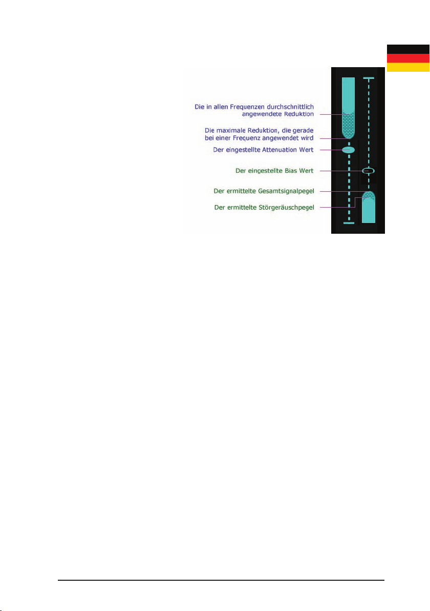
Attenuation/Absenkung
In der Voreinstellung regeln die Drehregler die Stärke der Geräuschreduktion, die
auf das Signal im jeweiligen Kanal angewendet wird. Dies zeigt die linke Hälfte des
Displays an. Das Fadersymbol zeigt die aktuelle Einstellung an und der Bargraph
zeigt die effektive Reduktion an, die sich auf den gesamten Frequenzbereich des
Signals auswirkt. Die ausgefüllte Säule zeigt den Durchschnittswert, die schattierte
Säule zeigt den Maximalwert.
Bias
Nach Druck auf den Drehregler regelt dieser den Bias. Der Bias wird in der
rechten Hälfte des jeweiligen Displays angezeigt. Drücken Sie den Regler noch
einmal, um zurück zur Steuerung der Attenuation zu gelangen. Die Drehregler
schalten nach einer kurzen Zeit von selber zur Steuerung der Attenuation zurück.
Die Regelung des Bias geht von der Nullposition aus. Das Fadersymbol zeigt
den aktuell eingestellten Wert. Wenn Sie den Bias erhöhen, wird mehr vom
Signal als Störgeräusch deniert. Dadurch kann der Prozess mehr Störungen
entfernen, was eventuell eine Kompression des Nutzsignals verursachen und
zu einem trocken Klang führen kann. Reduzieren Sie den Bias, wird weniger
Singalanteil als Geräusch deniert. Dadurch verbleibt mehr Atmo im Signal
aber es wird eventuell weniger störendes Geräusch entfernt. Der Bargraph auf
der rechten Seite des jeweiligen Displays zeigt den erkannten Langzeit-Signal-/
Störabstand (SNR). Die ausgefüllte Säule zeigt den erkannten Störpegel, die
schattierte Säule zeigt den erkannten Langzeitpegel des Nutzsignals; somit ergibt
die Differenz der beiden Säulen die erkannte Langzeit SNR. Wenn der Bias über
oder unter die Mittelstellung geregelt wird, verschiebt sich die Geräuscherkennung
gewissermaßen nach oben oder nach unten. Der Effekt zeigt sich in der
Page 17

Page 17
ausgefüllten Säule die wächst, wenn Sie den Bias erhöhen (und umgekehrt).
Linking/Verkopplung
Die beiden Kanäle des DNS2 können in drei verschieden Link-Modi arbeiten. Diese
werden der Reihe nach durch gleichzeitigen Druck auf beide Regler umgeschaltet.
Unlinked/Getrennt: Beide Kanäle DNS2 arbeiten unabhängig. Diesen Modus
verwenden Sie bei zwei getrennten Quellen, zum Beispiel einem geangeltes
Mikrofon und einem Sendemikrofon.
Linked/Verkoppelt: Die Audiokanäle bleiben getrennt aber ihre Steuerung ist
verkoppelt. Dieser Modus ist besonders für Stereosignale geeignet. (Wenn analoge
Eingänge verwendet werden, ist auch die Gainregelung verkoppelt, d.h. wenn
beide auf Mikrofon oder beide auf Line gesetzt sind. Wenn ein Kanal auf Line und
der andere auf Mikrofon steht, arbeiten die Gainregler unabhängig voneinander.)
Mono Split/Mono aufgeteilt: Eingang 2 ist dabei nicht aktiv. Das Signal am ersten
Eingang wird auf beide Kanäle verteilt. Die Signalverarbeitung beider Kanäle bleibt
unabhängig, wodurch Sie das gleiche Eingangssignal auf zwei verschiedene Arten
bearbeiten können oder, indem Sie die DNS für einen Kanal deaktivieren, eine
unbearbeitete und eine bearbeitet Version zur Verfügung haben.
Eingangswahl und Link Mode werden unten am Display angezeigt. Der Linked
Modus wird durch ein ‘=’ –Symbol, der Mono Split Modus durch ein ‘>’ –Symbol
angezeigt. Die Eingangswahl wird durch M/L/D (Mikrofon, Line, Digital) angezeigt,
gefolgt von einer 1 oder 2, je nach Eingangskanal. Im Mono Split Mode zeigen
daher beide Kanäle eine 1.
Weitere Informationen
Panel lock/Verriegelung
Der Lock-Schalter mit dem Schlosssymbol an der Geräteseite des DNS 2
deaktiviert alle Regler auf der Vorderseite, der Ein-/Ausschalter ausgenommen.
Normalerweise steht er auf OFF (Schalter oben). Schalten Sie ihn auf ON (Schalter
unten), um versehentliches Verstellen der Parameter auf der Frontseite zu
verhindern.
Bildschirmschoner
Die Intensität des Displays und der LEDs auf der Frontseite wird nach einer Weile
ohne Bedienaktivität reduziert. Sobald wieder etwas bedient wird, erhöht sich die
Helligkeit wieder.
Signalpegel LEDs
Zweifarbige LEDs zeigen den Singalpegel für jeden Kanal:
■
Off = Stille
■
grün = normal
■
rot = nahe Clipping
Page 18

Page 18
Synchronisations-LED
Die Sync LED zeigt den Status der aktuellen Sync Quelle wie folgt:
Input switch Digital input lock Sync status Sync source Audio source Sync LED
Analog No Normal Internal Analog Off
Digital No Error Internal Mute Red
Analog Yes Normal External Analog Green
Digital Yes Normal External Digital Green
Speichern der Einstellungen
Sobald für ein paar Sekunden keine Einstellungen am DNS2 vorgenommen
werden, reduzierten Tasten und Anzeigen die Helligkeit und die aktuellen
Einstellugen werden gespeichert. Beim Einschalten des DNS2 werden die zuletzt
gespeicherten Einstellungen wieder aufgerufen.
Ein- und Ausschalten
Geräte ab der Seriennummer DNS2-2-11017 schalten sich automatisch ein, sobald
die externe Stormversorgung zugeführt wird. Mit der Power Taste schalten Sie den
DNS2 an und aus. Falls es ein Problem gibt, ermöglicht ein Drücken der Power
Taste für 5 Sekunden oder länger ein “hartes” Abschalten.
Page 19
Page 19
Zusammenfassung der Bedienung
LEARN
Ist LEARN aktiviert, werden
Stärke und Spektralverteilung
des Störgeräusches
kontinuierlich ermittelt. Dies ist
der normale Arbeitsmodus.
Wird LEARN ausgeschaltet,
bleiben die gerade ermittelten
Werte eingeforen.
Bias
Die durch LEARN ermittelten
Werte für das Störgeräusch
werden mit Bias erhöht (mehr
entdeckte Störungen) oder
vermindert (weniger entdeckte Störungen).
Attenuation
Attenuation bestimmt, wie stark das Störsignal reduziert werden soll.
Daumenregel
LEARN und Bias bestimmen was als Störung eingestuft wird.
Attenuation bestimmt, wie stark die ermittelte Störung reduziert wird.
Page 20

Page 20
HAFTUNGSAUSSCHLUSS
Diese deutsche Übersetzung dient lediglich der Verbraucherfreundlichkeit.
Alle anderen Teile dieses Handbuchs in englischer Sprache, einschließlich der
aber nicht beschränkt auf die Konformitätserklärung, Spezikation, Lizenz und
Beschränkten Gewährleistung, gelten in vollstem Umfang des Gesetzes für alle
Kunden und Benutzer, mit vollständiger Wirkung und Konsequenz überall und
weltweit. Bei Abweichungen zwischen deutschem und englischem Text gilt die
englische Version.
Page 21

Page 21
Physical
Page 22
Page 22
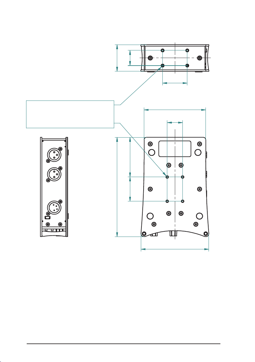
25
100
110
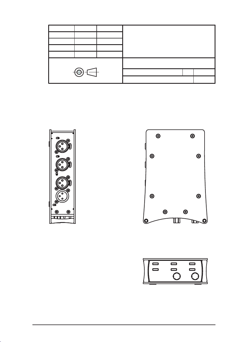
HOLES (8 PLACES) TAPPED ISO M4 FOR
CUSTOM MOUNTING APPLICATIONS
WARNING: SCREW PENETRATION 8MM MAX
164 44
25
40
40 65,5
Mounting the DNS 2
You may mount the DNS 2 on a camera or other equiment using the mounting
holes on the underside and rear of the unit. Refer to these diagrams for dimensions
and mounting positions.
Page 23
Page 23
DRAWN
NAME
CH
DATE
13/04/2016
CEDAR Audio Limited
TITLE
SIZE: A3
DWG NO: 20160413CH01
REV: A
FILE: dns2mounting.pdf
SHEET 1 OF 1
UNLESS OTHERWISE STATED, DIMENSIONS ARE IN MM
GENERAL TOLERANCE ±0.1
20 Home End, Fulbourn, Cambridge CB21 5BS, United Kingdom
www.cedaraudio.com +44 (0)1223 881771
THIRD ANGLE PROJECTION
DNS 2 - MOUNTING DIMENSIONS
This drawing is the property of CEDAR Audio Limited and may not be
copied or disclosed to any third party without prior consent.
Montage des DNS 2
Sie können den DNS 2 an einer Kamera oder anderem Equipment mit den
Montagegewinden auf der Unter- und Rückseite des Gerätes befestigen.
Einzelheiten entnehmen Sie bitte dem Diagramm.
Page 24

Page 24
SPECIFICATION
Inputs
Line input
Connector: Balanced XLR3F
Impedance: 10kOhm
Nominal signal level (0dB gain): +4dBu
ADC line up (0dB gain): +4dBu : -20dBFS
Clipping level (0dB gain): +24dBu
Dynamic range (0dB gain): > 102dB (AES17 unweighted)
THD+N (0dB gain): < 0.005%
Gain range: -6dB to +54dB
Microphone input
Connector: Balanced XLR3F
Impedance: 2kOhm
Gain range: 18dB to 78dB
ADC line up (36dB gain): -32dBu : -20dBFS
Dynamic range (36dB gain): > 102dB (AES17 unweighted)
THD+N (36dB gain): < 0.005%
Phantom Power
Type: P48 (IEC61958)
Unloaded voltage: +48V ± 4V
Current available: 10mA per microphone
Short circuit protection: Indenite
Digital input
Connector: Balanced XLR3F
Format: AES3 (IEC60958) or AES11 (DARS)
Sample rate sync range: 40kHz to 100kHz
Outputs
Line output
Connector: Balanced XLR3M
Nominal signal level: +4dBu
DAC line up: -20dBFS : +4dBu
Maximum output: +24dBu
Dynamic range: > 102dB (AES17, unweighted)
THD+N: < 0.005%
Minimum load impedance: 600 Ohm
Short circuit protection: Indenite
Digital output
Connector: Balanced XLR3M
Format: AES3 (IEC60958)
Sample rate (internal sync): 48kHz (±50ppm)
Sample rate (external sync): locked to digital input
Page 25

Page 25
DSP
AD/DA conversion
Resolution: 24-bit linear PCM
Sample rate (internal sync.): 48kHz
Sample rate (external sync.): 40kHz to 100kHz
DSP Processor
Type: Floating point
Resolution: 40-bit
Peak computation: 2.4 GFLOP/s
Sample rates: 44.1kHz, 48kHz, 96kHz
Power
Power input
Voltage: 8V to 17.5V (nominal 12V)
Connector: XLR4M (pin1 -, pin4 +)
Reverse polarity protection: Indenite
Over-voltage protection: Indenite, up to 50V
Power consumption (digital I/O): 3W typical
Power consumption (analog I/O): 4W typical
Max power consumption @ 12V: 4.5W (P48 off), 6W (P48 on)
Power adapter
Input voltage: 85VAC - 250VAC, 50 - 60Hz
Input power: <15W
Input connector: UK/US/EU
Output voltage: 12V
Output current: 1A (max.)
Output connector: XLR4F (pin1 -, pin4 +)
E&OE.
The Company reserves the right to change specications without notice.
Page 26

Page 26
DECLARATION OF CONFORMITY
Date of issue 18 April 2016
Equipment CEDAR DNS 2
Manufacturer CEDAR Audio Ltd
Address 20 Home End, Fulbourn, Cambridge CB21 5BS, UK
This is to certify that the aforementioned equipment, when used in accordance with
the instructions in this manual, fully conforms to the protection requirements of the
following EC Council Directives: on the approximation of the laws of the member
states relating to:
■
2004/108/EEC Electromagnetic Compatibility Directive
Applicable standards: EN 61000-6-1:2007
EN 61000-6-3:2007+A1:2011
■
2006/95/EC Low Voltage Directive
Applicable standard: EN 60065:2002+A12:2011
In order to comply with EMC regulations, you must connect the DNS 2 using metalshelled connectors and good quality shielded cable.
Restriction of Hazardous Substances (RoHS) Directive
All hardware products and sub-assemblies manufactured by CEDAR Audio Ltd
are designed to be compliant with Directive 2002/95/EC, Restriction of Hazardous
Substances. The manufacturing processes include the assembly of purchased
components and/or sub-assemblies from various sources. Any statement of
RoHS compliance made by CEDAR Audio Ltd may be based, in part or in full,
on statements provided by suppliers. Thus whilst every effort is made to ensure
compliance, CEDAR Audio Ltd may not have undertaken independent tests to
establish the compliance of such components and/or sub-assemblies.
Waste Electrical and Electronic Equipment (WEEE) Directive
In accordance with Directive 2002/96/EC, Waste Electrical and Electronic
Equipment, CEDAR Audio Ltd will provide its customers with information about
local organisations that can reprocess CEDAR products that have reached their
end of use. Alternatively such products can be returned to CEDAR Audio Ltd in the
UK at the owner’s cost and they will then be reprocessed correctly free of charge.
Page 27

Page 27
CONTACT INFORMATION
Headquarters:
CEDAR Audio Ltd,
20 Home End, Fulbourn, Cambridge, CB21 5BS, United Kingdom
t: +44 1223 881771
f: +44 1223 881778
e: [email protected]
USA Ofce:
CEDAR Audio USA
43 Deereld Road, Portland, ME 04101-1805, USA
t: +1 207 828 0024
f: +1 207 773 2422
e: [email protected]
German Ofce:
CEDAR Deutschland
Görlitzer Str. 3, D-49525 Lengerich, Deutschland
t: +49 5481 945087
f: +49 5481 945088
e: [email protected]
Web:
www.cedaraudio.com
Worldwide Dealer List:
For a current dealer list, please visit www.cedaraudio.com.
Page 28

Page 28
LICENCE AND LIMITED WARRANTY
1. DEFINITIONS
In this Licence and Limited Warranty the following words and phrases shall bear the following meanings:
‘the Company’ is CEDAR Audio Limited of 20 Home End, Fulbourn, Cambridge CB21 5BS, UK;
‘a/the System’ means an instance of the DNS 2 sound processing system comprising hardware
and software developed by the Company;
‘this Document’ means this Licence and Limited Warranty.
2. ISSUE AND USE OF THE SYSTEM
2.1 The terms and conditions of this Document are implicitly accepted by any person or body corporate who
shall at any time use or have access to the System, and are effective from the date of supply of the
System by CEDAR Audio Limited to its immediate customer.
2.2 The Company hereby grants to the Licensee and the Licensee agrees to accept a
non-exclusive right to use the System.
3. PROPERTY AND CONFIDENTIALITY
3.1 The System contains condential information of the Company and all copyright, trade marks, trade
names, styles and logos and other intellectual property rights in the System including all documentation
and manuals relating thereto are the exclusive property of the Company. The Licensee acknowledges
that all such rights are the property of the Company and shall not question or dispute the ownership of
any such rights nor use or adopt any trading name or style similar to that of the Company.
3.2 The Licensee shall not attempt to reverse engineer, modify, copy, merge or transcribe the whole or any
part of the System or any information or documentation relating thereto.
3.3 The Licensee shall take all reasonable steps to protect the condential information and intellectual
property rights of the Company.
4. LIMITED WARRANTY AND POST-WARRANTY OBLIGATIONS
4.1 The Company warrants that a System will perform substantially in accordance with the appropriate
section of its accompanying product manual for a period of one year from the date of supply to the
Company‘s immediate customer.
4.2 The Company will make good at its own expenses by repair or replacement any defect or failure that
develops in a System within one year of supply to the Company‘s immediate customer.
4.3 The Company shall have no liability to remedy any defect, failure, error or malfunction that arises as
a result of any improper use, operation or neglect of a System, or any attempt to repair or modify a
System by any person other than the Company or a person appointed with the Company‘s prior written
consent.
4.4 In the case of any defect or failure in a System occurring more than twelve months after its supply
to the Company‘s immediate customer the Company will at its option and for a reasonable fee make
good such defect or failure by repair or replacement (at the option of the Company) subject to the faulty
equipment having rst been returned to the Company. The Company will use reasonable efforts to
return repaired or replacement items promptly, all shipping, handling and insurance costs being for the
account of the Licensee.
4.5 The above undertakings 4.1 to 4.4 are accepted by the Licensee in lieu of any other legal remedy
in respect of any defect or failure occurring during the said period and of any other obligations or
warranties expressed or implied including but not limited to the implied warranties of saleability and
tness for a specic purpose.
4.6 The Licensee hereby acknowledges and accepts that nothing in this Document shall impose upon
the Company any obligation to repair or replace any item after a time when it is no longer produced
or offered for supply by the Company or which the Company certies has been superseded by a later
version or has become obsolete.
5. FORCE MAJEURE
The Company shall not be liable for any breach of its obligations hereunder resulting from causes beyond its
reasonable control including, but not limited to, res, strikes (of its own or other employees), insurrection or
riots, embargoes, container shortages, wrecks or delays in transportation, inability to obtain supplies and raw
materials, or requirements or regulations of any civil or military authority.
Page 29

Page 29
6. WAIVER
The waiver by either party of a breach of the provisions hereof by the other shall not be construed as a waiver
of any succeeding breach of the same or other provisions, nor shall any delay or omission on the part of
either party to exercise any right that it may have under this Licence operate as a waiver of any breach or
default by the other party.
7. NOTICES
Any notices or instruction to be given hereunder shall be delivered or sent by rst-class post or telecopier to
the other party, and shall be deemed to have been served (if delivered) at the time of delivery or (if sent by
post) upon the expiration of seven days after posting or (if sent by telecopier) upon the expiration of twelve
hours after transmission.
8. ASSIGNMENT AND SUB-LICENSING
The Licensee may at his discretion assign a System and in doing so shall assign this License its rights and
obligations to the purchaser who shall without reservation agree to be bound by this License. The original
Licensee and any subsequent Licensees shall be bound by the obligations of this License in perpetuity.
9. LIMITATION OF LIABILITY
The Company‘s maximum liability under any claim including any claim in respect of infringement of the
intellectual property rights of any third party shall be, at the option of the Company either:
(a) return of a sum calculated as the price received for the System by the Company from its immediate
customer depreciated on a straight line basis over a one year write-off period; or
(b) repair or replacement of those components of the System that do not meet the warranties contained
within this Document.
The foregoing states the entire liability of the Company to the Licensee.
10. CONSEQUENTIAL LOSS
Even if the Company has been advised of the possibility of such damages, and notwithstanding anything else
contained herein the Company shall under no event be liable to the Licensee or to any other persons for loss
of prots or contracts or damage (whether direct or consequential) arising in connection with a System or
any modication, variation or enhancement thereof and including any documentation or data provided by the
Company or for any other indirect or consequential loss.
11. ENTIRE AGREEMENT
The Company shall not be liable to the Licensee for any loss arising in connection with any representations,
agreements, statements or undertakings made prior to the date of supply of the System to the Licensee.
12. TERMINATION
This Licence may be terminated forthwith by the Company if the Licensee commits any material breach of any
terms of this License. Forthwith upon such termination the Company shall have immediate right of access to
the System for the purpose of removing it.
13. SEVERABILITY
Notwithstanding that the whole or any part of any provision of this Document may prove to be illegal or
unenforceable the other provisions of this Document and the remainder of the provision in question shall
remain in full force and effect.
14. HEADINGS
The headings to the Clauses are for ease of reference only and shall not affect the interpretation or
construction of this Document.
15. LAW
This Document shall be governed by and construed in accordance with English law and all disputes between
the parties shall be determined in England in accordance with the Arbitration Act 1950 and 1979.
Page 30

Designed and manufactured by
CEDAR Audio Ltd
20 Home End
Fulbourn
Cambridge CB21 5BS
United Kingdom
www.cedaraudio.com
[email protected]
t: +44 1223 881771
interstage
Phistersvej 31, 2900 Hellerup, Danmark
Telefon 3946 0000, fax 3946 0040
www.interstage.dk
Copyright CEDAR Audio Ltd, © 2016
CEDAR is a registered trademark of CEDAR Audio Ltd
DNS One, DNS 2, DNS 8 Live, DNS 8 CS, DNS1000, DNS1500, DNS 2000 and DNS3000 are trademarks of
CEDAR Audio Ltd
E&OE, Subject to revision at the Company’s sole discretion
Page 30
- pro audio with a smile
 Loading...