

Page 1
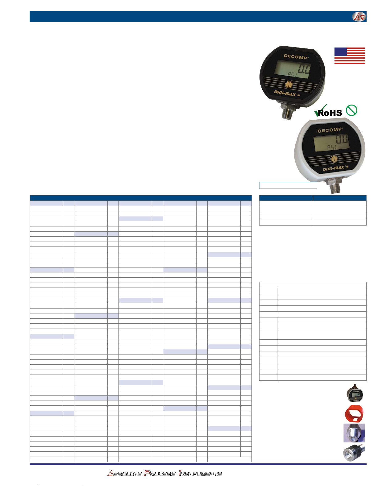
Cecomp® Battery Powered Digital Pressure Gauges with Min/Max & Selectable Units F16B, F16BN
Ranges and Resolution
See table below. Select range and default engineering units.
Consult factory for special engineering units.
Units may be changed to any listed under the same sensor range.
Resolution is fixed and limited to available display digits.
Accuracy
Accuracy includes linearity, hysteresis, repeatability
Standard accuracy: ±0.25% of full scale ±1 least significant digit
HA accuracy option: ±0.1% FS ±1 LSD, see ranges for availability
Sensor hysteresis: ±0.015% FS, included in accuracy
Sensor repeatability: ±0.01% FS, included in accuracy
Display
3 readings per second nominal display update rate
4 digit LCD, 0.5" H and 5 character 0.25" H alphanumeric
BL: Red LED backlight
Batteries, Battery Life, Low Battery Indication
2 AA alkaline included
B: Approx. 2000 hours
BL: Approx. 150-1500 hours depending on backlight usage
Low battery symbol on display
Controls & Functions
Front button turns gauge on or off, zeros gauge reference gauges,
and cycles through min./max. functions
Internal buttons for engineering unit selection, auto shutoff time,
min/max setup, calibration. Pass code protected setup & calibration.
BL: Front button activates backlighting for 1 minute
Min./Max. Functions
Minimum and maximum readings stored 3 times per second
Front button cycles through min. display, max. display, clear
Configurable for min. only, max. only, min./max., or none
Configure to clear or retain min./max. values at power off
Sensor Ranges and Engineering Units * -HA option not available Range codes are rounded off
3 psig *
85INH2OG
210GCMG
150MMHGG
150TORRG
200MBARG
200CMH2OG
2000MMH2OG
5 psig *
140INH2OG
350GCMG
260MMHGG
260TORRG
350MBARG
350CMH2OG
3500MMH2OG
15 psia Res
400INH2OA
1000GCMA
760MMHGA
760TORRA
1000MBARA
1000CMH2OA
100KPAA
0.1MPAA
15 psig vac *
15PSIVAC
30INHGVAC
400INH2OVAC
240ZINVAC
1000GCMVAC
760MMHGVAC
760TORRVAC
1000MBARVAC
1000CMH2OVAC
CECOMP Div. of
3PSIG
6INHGG
50ZING
7FTH2O
20KPAG
5PSIG
10INHGG
80ZING
12FTH2O
35KPAG
15PSIA
30INHGA
240ZINA
1BARA
1KGCMA
1ATMA
Res
15 psig vac *
.001
.001
100KPAVAC
0.1MPAVAC
.1
.01
1KGCMVAC
.1
15 psig Res
.1
.1
.1
.1
400INH2OG
1
.001
.01
Res
.001
.01
1000GCMG
760MMHGG
760TORRG
1000MBARG
1000CMH2OG
.1
.1
.1
.1
.1
.1
.1 ±15 psig *
1
–30INHG/15PSIG
.01
.01
±400INH2OG
.01
.01
.1
.1
1
.1
.1
1
±240ZING
±1000GCMG
±760MMHG
±760TORRG
±1000MBARG
±1000CMH2OG
±100KPAG
±0.1MPAG
1
.1
±1KGCMG
.0001
30 psia Res
.001
.001
.001
Res
850INH2OA
.01
.01
.1
.1
1
.1
2100GCMA
1600MMHGA
1600TORRA
2000MBARA
2100CMH2OA
.1
1
1
Res 30 psia Res
.1
.0001
1BARVAC
.001
.001
1ATMVAC
15PSIG
30INHGG
.001
.01
.01
.1
240ZING
.1
1
.1
.1
1
1
35FTH2O
100KPAG
0.1MPAG
1KGCMG
1BARG
1ATMG
.01
.1
.0001
.001
.001
.001
Res
±15PSIG
.01
.01
±30INHG
.01
1
.1
1
1
1
1
1
.1
.0001
.001
100 psia Res
±1BARG
.001
±1ATMG
.001
30PSIA
60INHGA
.01
.01
1
480ZINA
.1
1
1
1
1
1
200KPAA
0.2MPAA
2BARA
.1
.0001
.001
ABSOLUTE PROCESS INSTRUMENTS
Calibration
Pass code protected calibration
Non-interactive zero, span, and linearity, ±10% of range
Auto Shutoff
User selectable 1 minute to 8 hours or front button on/off
Factory default 5 minutes, unless other time is specified
Weight
Gauge: 9 ounces , shipping: 1 pound (approximately)
Housing
F16B: Extruded aluminum case, epoxy powder coated, ABS/ polycarbonate bezel (aluminum bezel optional), front and rear gaskets,
polycarbonate label
F16BN: ABS/polycarbonate NEMA 4X case, rear gasket, polycarbonate label
Connection and Material
1/4" NPT male fitting, all wetted parts are 316L stainless steel
Overpressure, Burst, Vacuum
Ranges using 3000 psig sensor: 5000 psig
Ranges using 5000 psig sensor: 7500 psig
All others: 2 X pressure range
3000 psi, 5000 psi, and 4 digit ranges 112.5% full scale out-ofrange display: 1– – – or I –.–.–.–
4 X sensor burst pressure rating, or 10,000 psi, whichever is less
Vacuum service: 15 psia, ±15 psig, 15 psig, 30 psia,
100 psig, 100 psia, 200 psig sensors
Under-range display (non-vacuum sensors): –Err
Environmental
Storage temperature: –40 to 203°F (–40 to 95°C)
Operating temperature: –4 to 185°F (–20 to 85°C)
Compensated temperature: 32 to 158°F (0 to 70°C)
2KGCMA
.001
2ATMA
.001
30 psig Res
30PSIG
2BARG
2ATMG
.01
.01
1
.1
1
1
1
1
1
.01
.1
.0001
.001
.001
.001
60INHGG
850INH2OG
480ZING
2100GCMG
1600MMHGG
1600TORRG
2000MBARG
2100CMH2OG
70FTH2O
200KPAG
0.2MPAG
2KGCMG
60 psig Res
60PSIG
4BARG
4ATMG
7BARA
7ATMA
.0001
.001
.001
.001
.0001
.001
.001
.001
.01
.1
1
1
1
1
1
1
1
.1 –15V200 psig *
.1
.1
.1
1
1
1
1
1
1
1
.1
120INHGG
1660INH2OG
960ZING
4200GCMG
3100MMHGG
3100TORRG
4100MBARG
4200CMH2OG
140FTH2O
400KPAG
0.4MPAG
4KGCMG
100PSIA
200INHGA
2770INH2OA
1600ZINA
7000GCMA
5200MMHGA
5200TORRA
7000MBARA
7000CMH2OA
700KPAA
0.7MPAA
7KGCMA
–15V100psig *
–15V100PSIG
–30INHG/100PSIG
–30V200INHGG
–400V2770INH2OG
–240V1600ZING
–760V5200MMHGG
–760V5200TORRG
–100V700KPAG
–0.1V0.7MPAG
–1V7BARG
–1V7KGCMG
–1V7ATMG
100 psig Res
200INHGG
2770INH2OG
1600ZING
7000GCMG
5200MMHGG
5200TORRG
7000MBARG
7000CMH2OG
230FTH2O
700KPAG
0.7MPAG
–15V200PSIG
–30INHG/200PSIG
–30V400INHGG
–400V5500INH2OG
–240V3200ZING
–100V1400KPAG
–0.1V1.4MPAG
–1V14BARG
–1V14KGCMG
–1V14ATMG
200 psig Res
400INHGG
5500INH2OG
3200ZING
480FTH2O
1400KPAG
1.4MPAG
14KGCMG
Res 300 psig Res
.1
.1
.1
1
1
1
1
1
.001
.01
.01
.01
100PSIG
.1
.1
1
1
1
1
1
1
1
.1
.1
.0001
7BARG
.001
7KGCMG
.001
7ATMG
.001
Res
.1
.1
.1
1
1
1
.001
.01
.01
.01
200PSIG
.1
.1
1
1
.1
1
.001
14BARG
.01
.01
14ATMG
.01
O ±0.25% Test Gauge Accuracy
O 316L Stainless Steel Wetted Parts
O User Configurable Min/Max, Units, Shutoff Time
Quick Link: cecomp.com/bat
300PSIG
610INHGG
4800ZING
700FTH2O
2000KPAG
2MPAG
20BARG
20KGCMG
20ATMG
500 psig Res
500PSIG
1020INHGG
1150FTH2O
3500KPAG
3.5MPAG
35BARG
35KGCMG
35ATMG
1000 psig Res
1000PSIG
2040INHGG
2300FTH2O
7000KPAG
7MPAG
70BARG
70KGCMG
70ATMG
2000 psig Res
2000PSIG
4070INHGG
4600FTH2O
14MPAG
140BARG
140KGCMG
140ATMG
3000 psig Res
3000PSIG
6100INHGG
6900FTH2O
20MPAG
200BARG
200KGCMG
200ATMG
5000 psig Res
5000PSIG
35MPAG
350BARG
350KGCMG
340ATMG
F16B range - time - options Standard housing
.1
F16BBL range - time - options Std. housing, backlit display
.1
F16BN range - time - options NEMA 4X housing
1
F16BNBL range - time - options NEMA 4X, backlit display
.1
1
Range—See table at left. Select a range code for default units.
.001
Please specify if vacuum gauge requires a minus sign.
.01
psi = PSI
.01
inHg = INHG
.01
oz/in2 = ZIN
inH2O = INH2O
.1
ftH2O = FTH2O
1
mmHg = MMHG
1
G gauge reference pressure
1
CPD inHg vac / psig pressure
.001
Time—auto shutoff time.
.01
.01
.01
1
1
1
1
.001
.01
.01
.01
1
1
1
.01
.1
.1
.1
1
1
1
.01
.1
.1
.1
1
.01
.1
.1
.1
5
10
30
ON
Options—add to end of model number. See price list for details.
HA
PM
FP
MC
CS
CC
TP
SM
CD
NC
TP
Top gauge port. Primarily used with tire pressure
applications. Not available with NEMA 4X models.
Accessories—order separately
RB
High visibility orange rubber boot protects gauge
for portable applications. Not for NEMA 4X models.
SCR14SS
Filter screen fitting keeps debris out of gauge
sensor. For food vacuum packaging applications.
303SS body, 100 micron 304SS screen.
CON14SS
Quick connector to install or remove gauge without tools. 304 stainless steel, urethane seal.
1220 American Way Libertyville, IL 60048
800-942-0315
HHHHHH
HHHHH
HHHHHH
HHHHH
HHHHHH
HHHHH
HHHHHH
HHHHH
HHHHHH
Made in USA
F16B
F16BN
NEMA 4X
How to Specify Type
torr = TORR
mmH2O = MMH2O
kg/cm2 = KGCM
g/cm2 = GCM
mbar = MBAR
bar = BAR
cmH2O = CMH2O
atm = ATM
kPa = KPA
MPa = MPA
VAC gauge reference vacuum
A absolute reference
5 minutes. Default if not specified.
10 minutes
30 minutes
No auto shutoff. On/off via front button.
High accuracy, ±0.1% FS ±1 LSD. See range table.
Panel mount, 4.1" x 4.1", n/a NEMA 4X
Sealed housing and CC for high humidity food process-
ing applications. F16BN in absolute ref. ranges only.
Metal front cover instead of plastic, n/a NEMA 4X
Case bottom stiffener plate, n/a NEMA 4X
Moisture resistant circuit board conformal coating
Top port, gauge port on top of case, n/a NEMA 4X
Surface mount plate, n/a NEMA 4X
Calibration data; 5 test points and date
NIST traceability documentation, 5 points and date
cecomp.com
Pb
© 10-18
Lead
Free
Page 2
Instructions F16B, F16BN
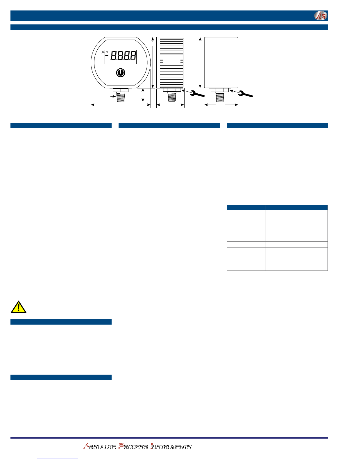
Dimensions
Low battery
voltage
indicator
Cecomp Electronics / Made in USA
¼" NPT
3.38" Standard
Installation Precautions
4 Read these instructions before using the gauge. Configuration
may be easier before installation. Contact the factory for assistance.
4 These products do not contain user-serviceable parts. Contact
us for repairs, service, or refurbishment.
4 Gauges must be operated within specified ambient temperature
ranges.
4 Outdoor or wash down applications require a NEMA 4X gauge or
installation in a NEMA 4X housing.
4 Use a pressure or vacuum range appropriate for the application.
4 Use fittings appropriate for the pressure range of the gauge.
4 Due to the hardness of 316 stainless steel, it is recommended
that a thread sealant be used to ensure leak-free operation.
4 For contaminated media use an appropriate screen or filter to
keep debris out of gauge port.
4 Remove system pressures before removing or installing gauge.
4 Install or remove gauge using a wrench on the hex fitting only.
Do not attempt to turn gauge by forcing the housing.
4 Good design practice dictates that positive displacement liquid
pumps include protection devices to prevent sensor damage
from pressure spikes, acceleration head, and vacuum extremes.
p Avoid permanent sensor damage! Do not apply vacuum to non-
vacuum gauges or hydraulic vacuum to any gauges.
p Avoid permanent sensor damage! NEVER insert objects into
gauge port or blow out with compressed air.
Gauges are not for oxygen service. Accidental rupture of sensor
diaphragm may cause silicone oil inside sensor to react with
oxygen.
Cecomp maintains a constant effort to upgrade and improve its products.
Specifications are subject to change without notice. See cecomp.com for
latest product information. Consult factory for your specific requirements.
WARNING: This product can expose you to chemicals including
nickel and chromium, which are known to the State of California to cause cancer or birth defects or other reproductive harm.
For more information go to www.P65Warnings.ca.gov
Types of Gauges
Bipolar ranges read positive pressure and vacuum in the same
units, and zero with the gauge port open.
1000 psi and higher sensor are a sealed reference type. They read
zero with the gauge port open are internally referenced to 14.7 psi.
Functionally similar to gauge reference sensors.
Absolute reference gauges read zero at full vacuum and
atmospheric pressure with the gauge port open. With an open
gauge port the readings will vary continuously due to the effects of
barometric pressure.
Selectable Ranges
Range Codes
The range code is part of the gauge model number and indicates
the default range when the gauge is ordered.
Selectable Ranges
Engineering units may be changed to any of those listed in the same
sensor range as shown in the range table.
Conversion
Engineering units are calculated from the factory default unit to the
newly selected units. The ranges listed under the psi sensor range
are rounded off.
XXXXX
8
8
8
8
8
3.5" NEMA 4X
2.88"
2
0.75"
Standard
1.65"
3.0"
Operation
Power-Up
Press and hold the front button for approximately 1 second.
The display is tested, the default full-scale range is indicated, the
full-scale range in the selected units are indicated, the display is
tested again, then the actual pressure and units are displayed.
Power-Up With Zero
This applies to gauge reference models only. Absolute reference
gauges do not use the zero feature since they read atmospheric
pressure under normal conditions.
Be sure the gauge port is exposed to normal atmospheric pressure
and no pressure is applied. The zeroing function is only activated
at each power-up and the stored zero correction is erased when
the gauge is shut off.
Press and hold the front button. The display is tested and then oooo
is displayed. The gauge is now zeroed. Release the button and the
full-scale range in the selected units are indicated, the display is
tested again, then the actual pressure and units are displayed.
Attempting to zero the gauge with pressure greater than approximately 3% of full-scale pressure or vacuum applied will result in an
error condition, and the display will alternately indicate Err 0 and
the actual measured pressure. The gauge must be powered down
to reset the error condition.
Normal Operation
Following the start-up initialization, the display indicates the pressure reading updated approximately 3 times per second. The auto
shutoff timer starts when the gauge is powered up or whenever the
button is pushed, unless the gauge shutoff time was set to zero for
on/off operation.
If excessive vacuum is applied to a pressure-only gauge, the display
will indicate -Err until the vacuum is released. Applying vacuum to
a gauge designed for pressure may damage the pressure sensor.
If excessive pressure is applied (112.5% over range), an out-ofrange indication of 1 – – – or 1.–.–.– will be displayed depending
on model.
Display Backlighting (BL models only)
Display backlighting can be turned on by momentarily pressing the
front button whenever the gauge is on. The backlighting will turn
on for one minute and then automatically shut off. This also restarts
the auto shutoff timer. The display backlighting will not be apparent
under bright lighting conditions.
Minimum and Maximum Readings
Gauges are normally configured with minimum and maximum
capture functions enabled. One or both can be disabled in the
Advanced Configuration mode.
Minimum and maximum readings are continuously stored and
updated whenever the gauge is on. The stored readings can be
manually cleared if desired. The MAX and MIN memory is also
cleared whenever the gauge is off unless configured to save the
readings.
Press and hold the button for about 1 second until MAX is displayed
alternating with the units. The maximum reading will be continuously updated. The gauge may be left in this mode.
After MAX is displayed, press and hold the button for about 1 second until MIN is displayed alternating with the units. The minimum
reading will be continuously updated. The gauge may be left in this
mode. If excessive vacuum is applied to a pressure-only gauge
while in this mode, the display will indicate -Err until the MAX/MIN
readings are cleared.
After MIN is displayed, press and hold the button again for about 1
second until * * * * is displayed. The MAX and MIN memory is not
erased and the gauge returns to normal operation with the display
indicating the current reading.
NEMA 4X
Turn at hex
2.0"
fitting only
Operation—continued
Press and continue to hold the button until the display indicates clr
MX/MN (about 3 seconds total) and then release the button. Both
maximum and minimum values are cleared and the gauge returns
to the normal mode and displays the current pressure.
Shut-Down
To shut off the gauge manually at any time, press and hold the button
until the display indicates OFF (about 5 seconds) and then release.
When an auto shutoff timer is used, the display indicates OFF five
seconds prior to auto shutoff. The button can be pressed to keep
the gauge on. The auto shutoff and backlight (if equipped) timers
are reset whenever the button is pressed and released.
If the gauge is set up without auto shutoff (on/off operation) it will
stay on until manually shut off or until the batteries are depleted.
Turn gauge off when not in use to conserve battery life.
Function Button Prompt (Release Button)
On Press for 1
Zero
(gauge ref.
Hi reading Press/hold Max > max. reading & units
Lo reading Press/hold MIN > min. reading & units
Exit Hi/Lo Press/hold
Clear Hi/Lo Press/hold Max > Clr mx/mn > actual reading
Clear, off Press/hold Max > Clr mx/mn > OFF
Press and
only)
Display test > default units > selected
second
units FUll scale > display test >
actual reading
Display test >
hold
selected units FUll scale >
display test > actual reading
SSSS
oooo
> actual reading
> default units >
CECOMP Div. of
ABSOLUTE PROCESS INSTRUMENTS
1220 American Way Libertyville, IL 60048
800-942-0315
cecomp.com
Page 3
Instructions F16B, F16BN
Advanced ConfigurationBasic Configuration Battery Replacement
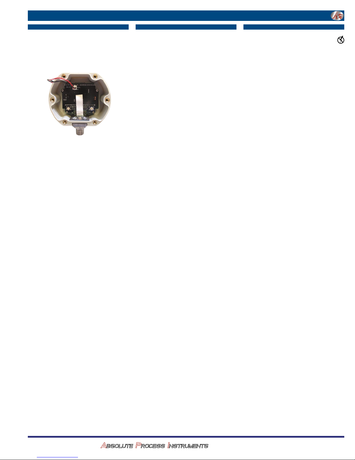
Accessing the Internal Buttons
1. Remove the 6 Phillips screws on the back of the unit.
2. Lift up the battery holder.
3. Move the battery holder to the side.
4. For gauges with the standad metal houseing, remove the battery
cradle if necessary to gain access to the two internal buttons
located near the lower right and left corners of the circuit board.
Auto Shutoff Time Selection
Auto shutoff time selection is done via the internal buttons to help
prevent accidental or unauthorized changes. The selected shut off
time is stored in non-volatile memory and will be retained even with
the battery off or batteries removed.
Remove the rear cover to gain access to the two internal buttons
located near the lower right and left corners of the circuit board.
With the gauge powered up, press and hold the DOWN button.
Release the button when the auto shutoff time is displayed on the
upper display.
The lower display will indicate AST M if the time displayed is in
minutes, and AST H if it in hours.
An auto shutoff time of 0 signifies that the auto shutoff feature is
disabled and the front button turns the gauge on and off.
Use the UP and DOWN buttons to select 0, 1, 2, 5, 10, 15, 20 or 30
minutes, or 1, 2, 4, or 8 hours.
When the desired time is displayed, press and release the front but-
ton to save the selection and return to normal operation.
Note: The gauge will automatically revert to normal operation if no
buttons are operated for approximately 15 seconds.
Replace the battery holder assembly and rear cover taking care not
to pinch the power wires between the cover and the case.
Engineering Unit Selection
Engineering unit selection (except compound ranges) is done
via internal buttons to help prevent accidental or unauthorized
changes. The selected engineering unit is stored in non-volatile
memory and will be retained even with the gauge off or batteries
removed. The available engineering units depend on the sensor
range and display resolution.
Compound (inHg/PSIG) gauges must be changed to display singleunit vacuum/pressure readings in the Advanced Configuration mode
before different engineering units can be selected.
The default engineering units are mathematically converted to the
newly selected engineering unit. When the gauge is powered up,
the originally configured range is displayed and then the conversion
with the selected engineering unit is displayed.
Powered the gauge up by holding the front button for 1 second.
Press and hold the internal UP button.
Release the button when the engineering units begin to flash.
Use the UP and DOWN buttons to scroll through the list of engineer-
ing units available for the pressure range of the sensor.
When the desired units are displayed, press and release the front
button to save the selection and return to normal operation.
Note: The gauge will automatically revert to normal operation if no
buttons are operated for approximately 15 seconds.
Replace the battery holder assembly and rear cover taking care not
to pinch the power wires between the cover and the case.
Advanced configuration requires a pass code for access and allows
more features to be configured.
Remove the rear cover to gain access to the buttons located near
the lower right and left corners of the circuit board.
With the gauge off, press and hold the UP button. Then press the
front button. Release all buttons when the display indicates CFG
and the program version then the full-scale range is indicated and
the display is tested.
The display then indicates _ _ _ _ with the first underscore blinking, and with CFGPC (configuration pass code) on the character
segments.
Note: The gauge will automatically revert to normal operation if
no buttons are operated for approximately 15 seconds. To cancel
and return to normal operation, press and release the front button
without entering any pass code characters.
Pass Code Entry
The factory default is 3510, but this may be changed by the user
under the Pass Code Configuration section.
1. Use the UP or DOWN buttons to set the left-most digit to 3.
2. Press and release the front button to move to the next position.
The 3 will remain, and the second position will be blinking.
3. Use the UP or DOWN buttons to select 5.
4. Press and release the front button to index to the next position.
35 will remain, and the third position will be blinking.
5. Use the UP or DOWN buttons to select 1.
6. Press and release the front button to index to the next position.
351 will remain, and the fourth position will be blinking.
7. Use the UP or DOWN buttons to select 0.
8. Press and release the front button to proceed with configuration
procedures.
If an incorrect pass code is entered, the gauge will return to the
start of the pass code entry sequence.
Factory/User Configuration
The upper display section will be blank, and the lower section will
display either USER_ or FCTRY.
If USER_ is selected, the user configuration can be modified as
described in the following steps.
To select USER_, press and release the DOWN button.
The lower display will indicate USER_.
Press and release the front button to continue.
If FCTRY is selected, the existing user configuration will be replaced
by the original factory configuration.
To select FCTRY, press and release the UP button.
The lower display will indicate FCTRY.
Press and release the front button to restore the factory configura-
tion and restart the gauge.
Max/Min Configuration
Use the UP and DOWN buttons to select from the following:
MX/MN Both highest and lowest values will be captured
MX/--- Only highest value will be captured
--/MN Only lowest value will be captured
--/-- Capture feature is disabled
Press and release the front button to move to the next parameter.
Max/Min Memory
The upper display section will indicate clr.
Use the UP and DOWN buttons to select from the following:
AUTO Automatically clear max. and min. values when the
gauge is powered off
MAN Manually clear max. and min. values
Press and release the front button to move to the next parameter.
Gauge Type Configuration
This will only appear with 15, 100, or 200 psig ranges that were
originally ordered as compound gauges.
Use the UP and DOWN buttons to select from the following:
-/+EU Vacuum is indicated as negative pressure in the
selected engineering units
CMPND Vacuum is negative INHG, pressure is PSIG. This setting
will disable engineering unit selection.
Press and release the front button to save the user configuration
and restart the gauge.
Replace the rear cover taking care not to pinch the power wires
between the cover and the case.
A low battery indication will be shown in the upper lefthand corner of the display when the battery voltage falls
sufficiently. The batteries should be replaced soon after the
indicator comes on or unreliable readings may result.
1. Remove the 6 Phillips screws on the back of the unit.
2. Lift up the battery holder.
3. Remove batteries by lifting up the positive end of the battery
(opposite the spring) taking care not to bend the battery holder
spring.
4. Discard old batteries properly, do not discard into fire, sources
of extreme heat, or in any hazardous manner.
5. Always replace both batteries at the same time with high quality
alkaline batteries.
6. Install batteries with correct orientation. Incorrect polarity will
damage the gauge. The negative (flat) end of each battery
should be inserted first facing the battery holder spring.
7. Replace battery holder and back cover, including the rubber
gasket and reinstall the six screws.
CECOMP Div. of
ABSOLUTE PROCESS INSTRUMENTS
1220 American Way Libertyville, IL 60048
800-942-0315
cecomp.com
Page 4
Instructions F16B, F16BN
Gauges are calibrated at the factory using equipment traceable to
NIST. There is no need to calibrate the gauge before putting it into
service. Calibration intervals depend on your quality control program requirements, although many customers calibrate annually.
Calibration should only be performed by qualified individuals using
appropriate calibration standards and procedures. The calibration
equipment should be at least four times more accurate than the
gauge being calibrated.
The calibration system must be able to generate and measure pressure/vacuum over the full range of the gauge.
A vacuum pump able to produce a vacuum of 100 microns (0.1
torr or 100 millitorr) or lower is required for vacuum and absolute
gauges.
Warning: application of vacuum to non-vacuum models may result
in irreparable damage to the sensor.
Allow the gauge to acclimate to ambient temperature for 20
minutes.
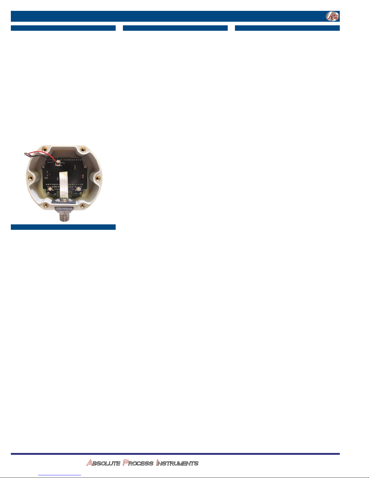
Remove the rear cover to gain access to the UP and DOWN buttons
located near the lower right and left corners of the circuit board.
Install fresh batteries.
Calibration
Entering Calibration Mode
With the gauge off, press and hold the DOWN button. Then press
the front button. Release all buttons when the display indicates CAL.
The display begins by indicating the full-scale positive pressure
rating of the gauge in the engineering units as configured by the
factory, and then shows all display.
Before the gauge enters the Calibration Mode, the display initially
indicates _ _ _ _ with the first underscore blinking, and with CALPC
(calibration pass code) on the lower display.
Note: The gauge will automatically revert to normal operation if
no buttons are operated for approximately 15 seconds. To cancel
and return to normal operation, press and release the front button
without entering any pass code characters.
Enter the User-Modifiable Pass Code
The factory default is 3510, but this is user changeable.
1. Use the UP or DOWN buttons to set the left-most digit to 3.
2. Press and release the front button to move to the next position.
The 3 will remain, and the second position will be blinking.
3. Use the UP or DOWN buttons to select 5.
4. Press and release the front button to index to the next position.
35 will remain, and the third position will be blinking.
5. Use the UP or DOWN buttons to select 1.
6. Press and release the front button to index to the next position.
351 will remain, and the fourth position will be blinking.
7. Use the UP or DOWN buttons to select 0.
8. Press and release the front button to proceed with configuration
procedures.
If an incorrect pass code is entered, the gauge will return to the
start of the pass code entry sequence.
Calibration Mode
The gauge enters and remains in the calibration mode until
restarted manually or power is removed. Features not related to
calibration are disabled and compound range models are set for the
same engineering units for pressure and for vacuum.
The calibration may be performed in any of the available engineering units as well as percent (PCT). For greatest accuracy, use the UP
and DOWN buttons to select engineering units for calibration with
highest resolution (highest number of display counts). Press and
Calibration—continued
release the front button when the appropriate engineering units are
displayed. Suggested units are listed below.
Sensor Suggested units for calibration
5 PSI 5.000 PSI
15 PSI 775.7 MMHG (TORR)
30 PSI 61.08 INHG
50 PSI 50.00 PSI
60 PSI 60.00 PSI
100 PSI 7.031 KG/CM2
200 PSI 407.2 INHG
300 PSI 610.8 INHG
500 PSI 500.0 PSI
1000 PSI 70.31 KG/CM2
2000 PSI 4072 INHG
3000 PSI 6108 INHG
5000 PSI 5000 PSI
Any 100.00 PCT (percent)
The display will then indicate the currently applied pressure in the
engineering units selected for calibration.
UP and DOWN Button Operation
Each time one of the calibration buttons is pressed and released
quickly, a small change is made to the digitized pressure signal. It
may take more than one of these small changes to result in a single
digit change on the display.
To make larger changes, press and hold the appropriate calibration
button. After about one second, the display will begin to change
continuously. Release the button to stop. Then make fine adjustments by pressing and quickly releasing the calibration buttons as
previously described.
Gauge Reference Pressure Gauges
Apply zero pressure by venting the gauge port to atmosphere. The
character display will alternate between ZERO and CAL. Adjust for
a display indication of zero using the UP and the DOWN buttons.
Apply full-scale pressure. The character display will alternate
between +SPAN and CAL. Adjust for a display indication of fullscale pressure using the UP and the DOWN buttons.
Apply 50% full-scale pressure. The character display will alternate
between +MID and CAL. Adjust for a display indication equal to
50% of full-scale pressure using the UP and the DOWN buttons.
Gauge Reference Vacuum Gauges
Apply zero pressure by venting the gauge port to atmosphere. The
character display will alternate between ZERO and CAL. Adjust for
a display indication of zero using the UP and the DOWN buttons.
Apply full-scale vacuum. The character display will alternate
between +SPAN and CAL. Adjust for a display indication of fullscale vacuum using the UP and the DOWN buttons.
Apply 50% full-scale vacuum. The character display will alternate
between +MID and CAL. Adjust for a display indication equal to
50% of full-scale vacuum using the UP and the DOWN buttons.
Absolute Reference Gauges
Apply full vacuum to the gauge. The character display will alternate
between ZERO and CAL. Press the UP and DOWN buttons to obtain
a display indication of zero.
Apply full-scale pressure. The character display will alternate
between +SPAN and CAL. Press the UP and DOWN buttons to obtain
a display indication equal to full-scale pressure.
Apply 50% of full-scale pressure. The lower display will alternate
between +MID and CAL. Press the UP and DOWN buttons to obtain
an indication equal to 50% of full-scale pressure.
Compound and Bipolar Gauges
In addition to the steps described above for pressure gauges, apply
full-scale vacuum. The character display will alternate between
–SPAN and CAL. Adjust for a display indication of actual applied
vacuum using the UP and the DOWN buttons.
For bipolar and –30.00inHg/+15.00psig compound range models
only, apply 50% full-scale vacuum. The character display will alternate between –MID and CAL. Adjust for a display indication equal
to 50% of full-scale vacuum using the UP and the DOWN buttons.
Save Calibration
Once the adjustments are complete, press and hold the front button until the display indicates – – – – then release the button to
store the calibration parameters in non-volatile memory and restart
the gauge.
Verify the pressure indications at 0%, 25%, 50%, 75% and 100%
of full scale.
Replace the rear cover taking care not to pinch the wires between
the cover and the case.
User-Defined Pass Code ConfigurationCalibration Preparation
Remove the rear cover to access the buttons located near the lower
right and left corners of the circuit board.
View Or Change User Configuration Pass Code
With the unit off, press and hold the UP button, then press the
front button.
Release all buttons when the display indicates CFG.
View Or Change User Calibration Pass Code
With the unit off, press and hold the DOWN button, then press the
front button.
Release all buttons when the display indicates CAL.
Enter Access Code 1220
Before the unit enters the view or change pass code mode, the
display initially indicates _ _ _ _ with the first underscore blinking,
and with CFGPC or CALPC on the character display.
Note: The gauge will automatically revert to normal operation if no
buttons are operated for approximately 15 seconds.
To cancel and return to normal operation, press and release the
front button without entering any pass code characters.
1. Use the UP and DOWN buttons to set the left-most digit to 1.
2. Press and release the front button to move to the next position.
The 1 will remain, and the second position will be blinking.
3. Use the UP and DOWN buttons to select 2.
4. Press and release the front button to index to the next position.
12 will remain, and the third position will be blinking.
5. Use the UP and DOWN buttons to select 2.
6. Press and release the front button to move to the next position.
1 2 2 will remain, and the fourth position will be blinking.
7. Use the UP and DOWN buttons to select 0.
8. Press and release the front button to proceed.
Note: If an incorrect access code was entered, the gauge will return
to the start of the access code entry sequence.
Once the access code has been entered correctly, the display will
indicate the existing user-defined pass code with CFGPC or CALPC
on the character segments.
1. Operate the UP or DOWN button to select the first character of
the new pass code.
2. When the correct first character is being displayed, press and
release the front button to proceed to the next pass code character.
3. Repeat above until the entire pass code is complete.
4. To exit, press and hold the front button. Release the button
when the display indicates – – – – to restart the gauge.
5. Replace the rear cover taking care not to pinch the power wires
between the cover and the case.
CECOMP Div. of
ABSOLUTE PROCESS INSTRUMENTS
1220 American Way Libertyville, IL 60048
800-942-0315
cecomp.com
 Loading...