

Page 1
CHAP.8
- DISMANTLING
8.1 - PUTTING THE MACHINE OUT OF ORDER
Should it be decided to put the machine out of order for some reason,
make sure that it is useless to everybody:
⇒ Remove and cut the electrical connections.
8.2 - DISPOSAL
Once the machine has been put out of order, the machine may be
eliminated. For correct disposal, contact any Company specialising in this
kind of service, paying attention to the material used for the various
components (see chap.1 par.2.2).
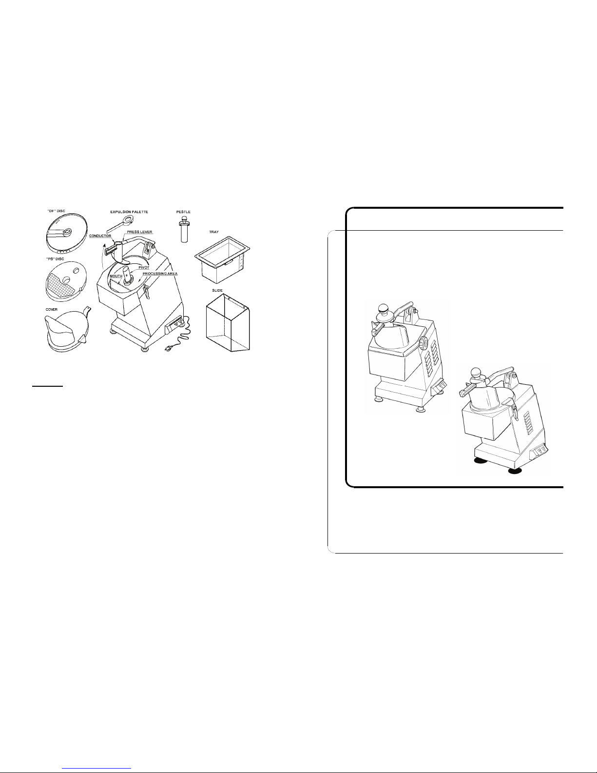
Fig. n°28 - View of the machine dismantled for cleaning
24
OPERATING AND MAINTENANCE MANUAL
VEGETABLE CUTTER
ed. 09/2001
1
Page 2

NOTE
- This manual has been written to supply our Client with all the
information regarding the machine and the applicable specifications for
its utilisation, including the instructions for use and maintenance that
allow for the best utilisation of the equipment, maintaining its efficiency
with time.
- This manual is to be consigned to the operators intended to use the
machine and see to its maintenance.
INDEX OF CHAPTERS
CHAP.1 - INFORMATION ON THE MACHINE
pag. 5
1.1 - GENERAL PRECAUTIONS
1.2 - DESCRIPTION OF THE MACHINE
1.2.1 - General description
1.2.2 - Construction particulars (materials used)
1.3 - SAFETY
1.3.1 - General Safety
1.3.2 - Electrical Safety
1.4 - Accessories + UTENSILS
1.4.1 - Accessories
1.4.1.1 - Standand Accessories
1.4.1.2 - Non-standard accessories
1.4.2 - Untensils
CHAP.2 - TECHNICAL INFORMATION
pag. 13
2.1 - VOLUME, WEIGHT, CHARACTERISTICS...
CHAP.3 - RECEIVING THE MACHINE pag. 14
3.1 - CONSIGNMENT OF THE MACHINE
3.2 - CHECKING PACKING AND CONTENTS
UPON RECEIPT
3.3 - DISPOSAL OF PACKING
CHAP.4 - INSTALLATION
pag. 15
4.1 - POSITIONING THE MACHINE
4.1.1 - Collecting device with tray
4.1.2 - Conveyor with slide
4.2 - ELECTRICAL INSTALLATION
4.2.1 - TM Monophase Vegetable cutter (220/230 V. 50 Hz)
4.2.2 - Vegetable cutter (400 V. 50 Hz)
2
6.2.7 - The machine does not switch on:
Check that all the safety devices are correctly positioned (Safety chapter
1.3); and that the supply plug and all the switches are inserted.
CAP.7
- CLEANING THE MACHINE
7.1 - GENERAL REMARKS
• The cleaning of the machine is an operation that should be performed
at least once daily, if necessary, more frequently.
• All the parts of the vegetable cutter, that come into direct or indirect
contact with the food to be processed, must be scrupulously cleaned.
Prior to performing any operation it is necessary to:
⇒ Remove the plug from the supply network
in order to completely isolate
the machine from the rest of the installation.
Beware of the risk factor of cutting and /or sharpened edges during
cleaning or manipulation of the discs .
7.2 - PRODUCTS TO BE USED
The machine must be cleaned with normal detergents at room
temperature, with the aid of a damp cloth. It must not be cleaned with
water jets or utensils, brushes and other objects that may superficially
damage the machine.
N.B.
DO NOT PUT ANY OF THE COMPONENTS IN THE DISHWASHER.
7.3 - PROCEDURE TO BE FOLLOWED:
Unplug the machine from its electrical supply.
Remove the cover and all the discs, the palette, the
pestle, the tray and/or the slide.
Accurately clean inside to opening, the entire processing area and the
supporting pivot for the discs.
Furthermore, clean all the external surfaces of the machine and pestle.
Dry with a cloth and reassemble the machine.
ATTENTION!
23
Page 3

6.1.3 - SWITCH LABELS
The switch labels may become stained and/or form holes with wear and
tear. Call the “Assistance Centre” for their replacement..
6.1.4 - ELECTRICAL LEAD
Periodically check the wear and tear on the electrical lead and call the
“Assistance Centre” should replacement be necessary.
6.1.5 - DISCS
The cutting edge of the blade may deteriorate with use.
For the DTV, DT 2, 3, 4, 7, 9 and PS 6, 8, 10, 20; discs, new ones will
have to be acquired.
For the DF 1, 2, 3, 4, 5, 8, 10, 14 e DQ 4, 6, 8, 10 discs, the blades may
be replaced. In such case, call the “Assistance Centre” specifying the
exact code of the disc.
6.2 - WHAT TO DO IF...
6.2.1 - The disc break is defective:
Check that the discs and disc holding pivot have been properly cleaned.
6.2.2 - The lid does not clamp shut:
Check that the lid has been correctly positioned and properly cleaned.
6.2.3 - The product is not properly cutted:
Check the wear and tear of the knives.
6.2.4 - The product is expelled with difficulty or badly cutted:
Check that the expulsion palette is assembled with the DT (all the ranges);
DF 1,2,3,4 and DQ 4 discs, that the tray is not full and that the opening is
not obstructed.
6.2.5 - The machine jams:
Ensure that the product to be processed is not frozen or too hard and that
the electrical current supplied is the same as that indicated by the
technical-registration plate
(Fig. n°19).
6.2.6 - The microswitch on the press lever and lid do not function:
Check that they are not blocked by dirt or other particles.
22
4.3 - ELECTRICAL DRAWING OF THE VEGETABLE CUTTER
4.4 - CHECKING THE FUNCTIONING ORDER
CHAP.5 - USE OF THE MACHINE pag. 19
5.1 - DISC ASSEMBLY
5.2 - PRODUCT LOADING AND CUTTING
CHAP.6 - MAINTENANCE AND PRACTICAL ADVICE pag. 21
6.1 - GENERAL REMARKS
6.1.1 - Belt
6.1.2 - Feet
6.1.3 - Switch labels
6.1.4 - Electrical lead
6.1.5 - Disc
6.2 - WHAT TO DO IF….
6.2.1 - The disc break is defective
6.2.2 - The lid does not clamp shut
6.2.3 - The product is not properly cutted
6.2.4 - The product is expelled with difficulty or badly cutted
6.2.5 - The machine jams
6.2.6 - The microswitch on the press lever and cover do not function
6.2.7 - The machine does not switch on
CHAP.7 - CLEANING THE MACHINE pag. 23
7.1 - GENERAL REMARKS
7.2 - PRODUCTS TO BE USED
7.3 - PROCEEDURES TO BE FOLLOWED
CHAP.8 - DISMANTLING pag. 24
8.1 - PUTTING THE MACHINE OUT OF ORDER
8.2 - DISPOSAL
3
Page 4
INDEX OF ILLUSTRATIONS
FIG. n°1 - General view of the Vegetable cutter mod.TM pag. 6
FIG. n°2 - Electrical safety device pag. 8
FIG. n°3 - Mechanical safety device pag. 8
FIG. n°3A - Electrical safety device pag. 8
FIG. n°4 - Position of the slide and tray to allow
for ignition pag. 9
FIG. n°5 - On-off card pag. 9
FIG. n°6 - Vegetable-pressing pestle pag.10
FIG. n°7 - Tray with magnetic sensor pag.10
FIG. n°8 - Product conveying slide pag.10
FIG. n°9 - Expulsion palette pag.10
FIG. n°10 - Disc shaft pag.11
FIG. n°11 - Utensil “DF” type pag.11
FIG. n°12 - Utensil “DT” type pag.11
FIG. n°13 - Utensil “DQ” type pag.12
FIG. n°14 - Utensil “PS” type pag.12
FIG. n°15 - Dimension and maximum volume pag.13
FIG. n°16 - Description of the packing pag.14
FIG. n°17 - Collecting device and tray pag.16
FIG. n°18 - Conveying device with slide pag.16
FIG. n°19 - Technical-registration plate pag.17
FIG. n°20 - Direction of disc rotation pag.17
FIG. n°21 - Triphase electrical installation drawing pag.18
FIG. n°21A - Monophase elecrtical installation drawing pag.18
FIG. n°22 - On-off switch pag.19
FIG. n°23 - Assembly of expulsion palette pag.20
FIG. n°24 - Assembly of coupled discs PS-DF pag.20
FIG. n°25 - Correct position pag.20
FIG. n°26 - Product loaded at the mouth of the lid pag.21
FIG. n°27 - Product loaded from the conductor on the lever pag.21
FIG. n°28 - View of the machine dismantled for cleaning pag.24
4 21
B Once all of the product inserted has been processed and by lifting the
thrusting lever, a safety mechanism will prevent the machine from
continued processing. Once more product has been loaded and the
lever has been lowered, the machine will automatically restart.
C Proceed as described in point 5.1 “A” for the replacement of discs and
thus change in processing. After this operation the electrical system
will prevent the machine from starting automatically; push the “l”
button to get it started again.
D If the collecting tray is used, empty its contents every 2-3 cycles. Use
of the machine when the tray is overfull may hinder the correct flow of
the cut product from the processing area, causing incorrect cutting,
jamming the machine or damage the motor.
CAP.6 - MAINTENANCE AND PRACTICAL ADVISE
6.1 - GENERAL REMARKS
Prior to performing any operation it is necessary to:
Remove the plug from the supply network in order to completely isolate
the machine from the rest of the installation
6.1.1 - BELT
There is no need to adjust the belt. It generally needs to be replaced after
3-4 years, in case of breakage call the “Assistance Centre”.
6.1.2 - FEET
With time the feet may deteriorate and lose their elasticity, thus
diminishing the stability of the machine. See to their replacement if this is
the case.
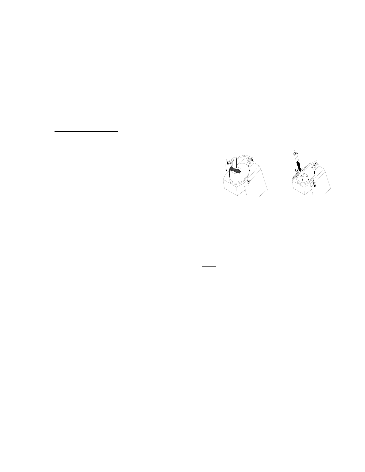
Fig. n°26 - Product loaded via opening
of the lid.
Fig. n°27 - Product loaded via
conductor on the lever
Page 5

5.2 - PRODUCT LOADING AND CUTTING
While the machine is operational one
must be correctly positioned to avoid
accidents. Ones body must always be
perpendicular to the processing
surface (
see Fig. n°25). Do not position
oneself so as to have dirrect
contact between parts of ones body
and the moving machine.
N.B. The product to be processed by
theTM must be loaded when the
motors are off.
The procedure is as follows:
A Load the product to be processed in the opening for the lid
(as per fig n°
26) .
If the product is small in size (like carrots, baby marrows etc.) load
the material via the conductor on the lever
(as per fig.n°27). Switch on the
machine and help the processing by gently pushing on the press or by
using the pestle if the opening is used
Fig. n°23 - Assembly of expulsion palette
Fig. n°24 - Assembly of coupled discs PS- DF
Fig. n°23 Fig. n°24
Case in which the expulsion palette must not be assembled
Fig. n°25 - Correct position
ATTENTION!
20
CHAP.1 - INFORMATION ON THE MACHINE
1.1 - GENERAL PRECAUTIONS
- The vegetable cutter must only be used by trained personnel, who are
perfectly familiar with the safety regulations contained in this manual.
- Provide timely training to personnel that may have to be in the vicinity
of the machine.
- Eventhough the machine is equipped with safety devices, avoid putting
ones hands close to the moving parts.
- Prior to cleaning or maintenance, disconnect the machine from its
electrical supply network.
- When intervening for the cleaning or maintenance of the Vegetable
cutter (and thus the protective devices are removed), carefully evaluate
the degree of risk involved.
- During the cleaning or maintenance, maintain ones concentration on
the operation being performed.
- Periodically check the condition of the electrical lead, a worn lead or
anyway one that is not intact represents serious danger of an electrical
nature.
- Should one presume or should the machine show signs of
malfunctioning it is advisable not to use it and call the “Assistance
Centre” to be found on the back of the manual.
- Do not use the Vegetable cutter for frozen products, meat and fish with
bones and any non-food products.
- Do not intervene directly in repairing the machine, but call an
authorized technician.
- Always use the press with pestle to cut the merchandise
- To avoid any kind of problem, do not overfill the conductor and do not
press too hard.
- The manufacturer is exempt of any responsibility in the following cases.
⇒ The machine is manipulated by unauthorized personnel;
⇒ Components are replaced by other non origninals and discs not
supplied by ourselves;
⇒ The instructions in this manual are not followed with attention;
⇒ The surfacaes of the machine are treated with inappropriate products.
5
Page 6

1.2 - DESCRIPTION OF THE MACHINE
1.2.1 - GENERAL
DESCRPTION
The TM Vegetable cutter was specifically designed to cut vegetables, fruit
and mozzarella cheese guaranteeing:
- maximum safety when being used, cleaned and under maintenance;
- maximum hygiene, attained thanks to a scrupulous selection of
material that comes into contact with the food, and to the elimination of
sharp corners on the parts of the vegetable cutter that come into
contact with the product, this achieving easy and complete cleaning
and facilitating dismantlement;
- the robustness and stability of all the components;
- maximum silence thanks to its belt transmission;
- great manageability.
Fig. n°1 - General view of the Vegetable cutter mod. “TM”
PESTLE
PRESS
PRESS HANDLE
HOPPER
STRUCTURE
HINGED CLASP
ELECTRICAL LEAD
ON OFF PUSH BUTTON
FEET
BASEMENT
COVE FASTENING
6
4.4 - CHECKING THE FUNCTIONING ORDER
Test the functioning order using the following procedures:
a) Push the on button “l” and then the off button “O” and check that the
buttons start and stop the machine respectively
(Fig. n°22).
b) Check that the motor stops and subsequently starts when lifting and
lowering the press lever.
c) Check the machine stops when the cover is removed and that it
restarts pushing the START “l” button only once the cover has been
replaced.
d) Check as per point “c” removing and repositioning the tray or slide.
CHAP.5
- USE OF THE MACHINE
5.1 - DISC ASSEMBLY
A Select the desired disc choosing from DF 1-2-3-4-5-8-10-14, DTV, DT
2-3-4-7-9, or DQ 4-6-8-10; after having removed the steel or aluminium
cover, position it on the disc holding shaft. Let it rotate normally until it
is completely hooked. Replace the cover clamping it shut with the
hinged clasps of the steel cover or the fastening handle of the
aluminium lid.
B (FOR CUTTING CUBES)
Select the desired coupled discs from PS8-DF8, PS10-DF10, PS20-
DF14. First insert the PS disc, with the hollow side facing to the right
when on is facing the machine. Then assemble the DF disc with the
same procedure described in point “A”
(see Fig. n°24).
NB: THE EXPULSION PALETTE MUST NOT BE ASSEMBLED
TOGETHER WITH THE COUPLED DISCS PS-DF
C Should the machine be supplied with the expulsion palette
(Fig. n°9), it is
advisable to use it together with the DF 1-2-3-5, DTV, DT 2-3-7-9, DQ4
discs. The palette must be assembled onto the disc holding pivot prior
to any other disc (
as per Fig. n°23). Then assemble the disc with the same
procedure described in point “A”.
Fig. n°22 - ON/OFF switch
ATTENTION!
19
Page 7

4.3 - ELECTRICAL DRAWING OF THE VEGETABLE CUTTER T.M.
Fig. n°21 - Drawing of 230/400 Volt threephase electrical
18
Fig. n°21-A - Drawing of 220 Volt monophase electrical installation
1.2.2 - COSTRUCTION PARTICULARS (Materials used)
The TM Vegetable cutter is built adopting material highly resistant to
mechanical wear and tear, structural shock, and the corrosive agents
normally found within the products to be processed.
Particularly:
- The processing hopper and base are in anodized alluminium, which
besides its high oxidation resistence, also guarantees hygienic contact
with food and the non-adherence of acid and salts.
- The structure, cover, press lifter, disc carrying shaft in AISI 304 o 430.
- Pestle, press, receiving tray, and control box in highly resistant plastic,
sutable for contact with food.
- The discs for processing the product are:
a) The DF, DQ and PS series have an alluminium supporting structure and
knives in AISI 420 steel.
b) The DT series have a plastic structure and knives in AISI 420 steel.
1.3 - SAFETY
1.3.1 - GENERAL SAFETY
The T.M. Vegetable cutter described in this manual adheres, as far as
mechanical, electrical and hygienic safety are concerned, to the
specifications laid down in:
MECHANICAL SAFETY
: 98/37.
ELECTRICAL SAFETY: 73/23/CEE; 89/336/CEE.
HYGIENIC SAFETY: 89/109/CEE. SPECIFICATIONS: EN 60335-1; EN 55014.
** The Vegetable cutter is endowed with specified measures for electrical
and mechanical protection in the processing phase as well as the cleaning
and maintenance phases. There is, however, a RISK FACTOR (CEE 98/37
Point 1.7.2) that may not be entirely eliminated, in this manual recalled in
form of ATTENTION.
This regards the danger of being cut derived from the manipulation of the
discs during their replacement and/or cleaning.
1.3.2 - ELECTRICAL SAFETY
The T.M. Vegetable cutter is endowed with sensor:
A on the press lever, able to block the functioning of the machine should
the lever be lifted beyond the block point of the lid and allows for the
automatic start at the moment the abovementioned dangerous
conditions are eliminated
(Fig. n°2).
7
Page 8

B on the hopper, able to block
the functioning of the machine should the cover be removed
(e.g. to
replace the discs) (Fig. n°3A),
and that allows for the volontary start of the
machine (
pushing the “l” button) only once the cover is in the closed
position, adequately clamped with the specific hinged clamps of the
steel lid and handle of the aluminium lid
(Fig.n°3)
Fig. n°2 - Electrical safety device
Fig. n°3 - Mechanical safety device
Fig. n°3A - Electrical safety device
LEVER WHEN LIFTED
(BEYOND THE BLOCK POINT)
LEVER WHEN
LOWERED SENSOR
SENSOR
STEEL COVER ALUMINIUM COVER
COVER
STEEL COVER
ALUMINIUM COVER
POSITION OF SENSOR
POSITION OF SENSOR
COVER
COVER HANDLE
HINGED CLAMPS
8
Furthermore check that the information on
the Technical-registration plate (fig. n°19)
corresponds to the information on the
consignment and other accompanying
documents.
4.2.2 - T.M. TRIPHASE VEGETABLE CUTTER (400 Volt, 50 Hz)
The T.M. Vegetable cutter is supplied with an electrical lead of 5x1 mm²
section; 1,5 m length.
Link the Vegetable cutter to a 400 Volt 50 Hz threephase supply network
by means of a CEI red plug, inserting a 10 A, ΔI = 0.03 A differentialmagnetothermical switch.
Ensure that the earthing network is perfectly functional.
Furthermore, check that the information on the Technical-registration plate
(
Fig. n°19) corresponds to the information on the consignment and other
accompanying documents.
Before permanently linking the machine to the threephase supply cable,
check the rotation direction of the discs (
for assembly see chap. 5.1.) with a
single pulse of the “l” (on) button immediately followed by a stop effected
by the “O” (off) button.
The blades should have an anti-clockwise rotation when looking at the
discs through the hole positioned on the press (
Fig.n°20).
Should the rotation direction not be exact, invert (inside the plug) two of
the three supply wires (black and grey).
The threephase engines assembled in the Vegetable cutter may work with
both 220V threephase current, as well as with 400V threephase current.
Unless otherwise specified, the machine whould be linked to a 400 V
supply; for adjustment to a 230V threephase supply network, request the
intervention of the “ASSISTANCE SERVICE”.
Fig. n°20 - Direction of disc rotation
Fig.n°19 -Technical-registration plate
17
Page 9

4.1.2 - CONVEYOR WITH “SLIDE”
Should the TM Vegetable cutter be supplied with a conveying slide,
position the same under the unloading opening
(Fig. n°18).
NB. For correct assembly:
Pass the screws through the holes of the slide pushing them down until
the slide is completely hooked in place.
4.2 - ELECTRICAL INSTALLATION
4.2.1 - T.M. MONOPHASE VEGETABLE CUTTER (220/230 Volt, 50 Hz)
The T.M. Vegetable cutter is supplied with an electrical lead of 3x1 mm²
Section; 1,5 m length, and with a ‘SHUKO’ plug.
Link the Vegetable cutter to a monophase 220/230 Volt 50 Hz network,
inserting a 10 A, ΔI = 0.03 A differential-magnetothermical switch.
Ensure that the earthing network is perfectly functional.
Fig. n°17 - Collecting device
with tray
Fig. n°18 - Conveing accessory “slide”
SENSOR
PUSHING
DIRECTION
16
C on the structure able to block the functioning of the machine should
the collecting tray or slide be incorrectly positioned at the unloading
opening, and that allows for the volontary start of the machine
(pushing the “I” button) only once the tray and slide are adequately
positioned.
Fig. n°4 - Position of the slide or tray to allow for ignition
Furthermore, the T.M. Vegetable cutter is endowed with a controlling
device made up of:
D an insulated IP 54 “O”
(Fig. n°5).
E an insulated IP 34 power card, made up of a transformer and two
homologated rays, run by a control box and by sensors positioned on
the tray, the slide and on the cover; able to switch the machine on and
off.
The T.M. Vegetable cutter allows for a N.V.R. device which, in case of
renewed tension after previous failure, allows for the machine to be
switched on exclusively by means of the START button “I”.
1.4 - ACCESSORIES + UTENSILS
1.4.1 - ACCESSORIES
The T.M. Vegetable cutter is supplied with many accessories. Some are
supplied as standard accessories, others only upon specific request by the
Client.
Fig. n°5 - On - Off card
9
Page 10

1.4.1.1 - STANDARD ACCESSORIES
Pestle: in non-toxic polyethilene facilitates cutting the product, introduced
via the conductor positioned on the press, in small pieces (
Fig.n°6)
Collecting tray:
in non-toxic polyethilene, in the “GASTRONORM”
dimension of 1/3, h=200; endowed with a magnetic sensor
(Fig. n°7).
1.4.1.2 - NON-STANDARD ACCESSORIES
Slide: in AISI 304 steel, replaces the tray and
facilitates the product falling into a recipient
generally positioned at the bottom of the
processing surface
(Fig. n°8).
Trays
: in non-toxic polyethilene in the
“GASTRONORM” DIMENSION OF 1/2, H=150
This too is endowed with a magnetic sensor.
Expulsion palette
: in AISI 304 steel is assembled
within the disc-holding pivot. Facilitates the
expulsion of the cutted product. It may be used
only with DTV, DT2 - 3 - 4 - 7 - 9, DF1 - 2 - 3 - 4
(Fig. n°9)
Fig. n°6 - Vegetable-pressing pestle Fig. n°7 - Tray with magnetic sensor
Fig. n°9 - Expulsion palette
Fig. n°8 - Product conveying slide
10
3.2 - CHECKING PACKING AND CONTENTS UPON RECEIPT
Upon receipt of the parcel containing the TM Vegetable cutter, accurately
check the packing to ensure that it has not been seriously damaged during
transportation. Upon examination, should the external packinging present
signs of manhandling, jolting or falling, it is necessary to point out the
damage to the transporter and, within three days of the delivery date
indicated on the documents, file a written report of any possible damage to
the machine.DO NOT TURN THE PACKING UPSIDE DOWN!! At the
moment of transportation, ensure that the same is solidly lifted by the 4
fundamental points (keeping it parallel to the floor).
3.3 - DISPOSAL OF PACKING
The packing components (cardboard, pallet (if necessary), plastic straps
and polyurethane foam) are products compatible with solid urban refuse;
for this reason they may be disposed of without difficulty. Should the
machine be installed in countries with particular specifications, dispose of
the packing as indicated by the laws in force in such countries.
CHAP.4
- INSTALLATION
4.1 - POSITIONING THE MACHINE
The surface upon which the machine will rest must be chosen bearing in
mind its encumbrance as indicated in Fig.n°15 (and thus be sufficiently
large); it must be even, dry, smooth, sturdy and stable, with a height of
roughly 80 cm from the floor. Furthermore, the machine must be
positioned in an environment with a maximum non-saline humidity of 75%
where the temperature ranges between +5°C and +35°C; in other words
an environment that does not cause the malfunctioning of the same.
4.1.1 - COLLECTING DEVICE WITH TRAY
Should the T.M. Vegetable cutter be supplied with a collecting tray,
position it under the unloading opening of the machine, so as to
adequately cover the unloading area, with the magnetic sensor facing
towards the inside of the machine (
fig. n°17).
15
Page 11

CAP. 3 - RECEIVING THE MACHINE
3.1 - CONSIGNMENT OF THE MACHINE
(see Fig. n°16)
The TM Vegetable cutter leaves our premises accurately packed; the
packing consist of: a) external box in sturdy cardboard;
b) the machine;
c) inserts to keep the machine stable;
d) tray;
e) pestle;
f) this manual;
g) certificate of conformity CE.
Fig. n°16 - Description of the packing
a)
c)
b)
d)
e)
f)
g)
14
Disc holder: in non-toxic plastic-coated steel
it is useful for collecting the discs, it is also
suitable for washing the discs in a dishwasher
(Fig.n°10).
1.4.2 - UTENSILS
The TM Vegetable cutter, upon request, may
be supplied with various kinds of discs,
suitable for different kinds of processing.
- DISCS FOR SLICING “DF”
:
They have an aluminium supporting structure
with AISI 420 steel knives.
The following discs are available:
DF1
DF2
DF3
DF4
DF5
specifically for tomatoes and peppers
DF8
DF10
DF14
Fig. n°10 - Disc shaft
Fig. n°11 - “DF” type utensil
- DISCS FOR SHREDDING “DT”
:
They have a plastic supporting structure, while
the body of the disc is in AISI 420 steel.
The following discs are available:
DTV
for grating
DT2
DT3
DT4
DT7
DT9 specifically for mozzarella
Fig. n°12 - “DT” type utensil
11
Page 12

- DISCS FOR CUTTING IN STICKS“DQ”
:
They have an aluminium supporting structure with AISI 420 steel knives.
The following discs are available:
DQ4
DQ6
DQ8
DQ10
- DISCS FOR CUTTING IN CUBES “PS”
:
They have an aluminium supporting structure with AISI steel knives.
The following discs are available:
PS8
coupled with DF8
PS10 DF10
PS20 DF14
Fig. n°13 - “DQ” type utensil
Fig. n°14 - “PS” type utensil
12
u.m. TM steel cover TM alluminium cover
Electrical supply
Mn
Tf
230 V./ 50 Hz
230-400 V./ 50 Hz
230 V./ 50 Hz
230-400 V./ 50 Hz
Power
watt / Hp 515 / 0.7 515 / 0.7
RPM rotations
g/min. 300 300
Feet position
G x H x I
mm 225 x 180 x 255
225 x 180 x 255
Dimensions
mm 510 x 280 x 460
(A x E x C)
510 x 280 x 460
(A x E x C)
Max dim.
mm 510 x 400 x 790
(A x F x B)
510 x 535 x 790
(A x D x B)
Packing dim.
mm 720 x 350 x 500 720 x 350 x 500
Nett weight
kg 20 23
Gross weight
kg 24 26
Noise level
dB
≤70 ≤70
CAP.2 - TECHNICAL INFORMATION
2.1. - ENCUMBRANCE, WEIGHT, CHARACTERISTICS ...
Fig. n°15 - Dimensions and maximum encumbrance
13
The electrical characteristics of the machine are indicated on a plate applied to its
back, before proceeding to the installation, see point 4.2 - ELECTRICAL
INSTALLATION.
 Loading...