

Page 1
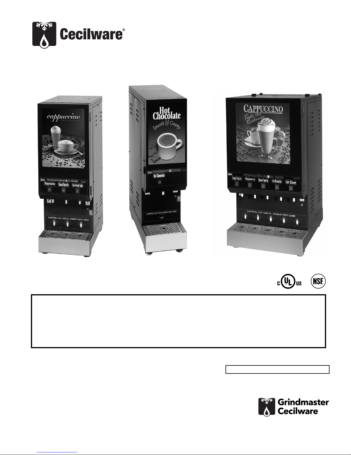
Powdered Beverage Dispenser
Operator Manual
GB Models 1, 2, 3, 4, 5, & 6
Model GB3M10-LD
Model GB5M10-LD
Safety Information..................2
Installation...............................3
Operation ................................6
Cleaning...................................8
Maintenance .........................10
Troubleshooting Guide.........13
Parts Diagram and List..........15
Wiring Diagrams ...................23
Thank you for purchasing this quality powdered beverage dispenser. For your safety and the safety of others,
read all warnings and the operator manual before installing or using the product. Properly instruct all operators.
Keep training records. For future reference, record serial number here:
Table of Contents
Model GB1HC
Grindmaster-Cecilware
4003 Collins Lane, Louisville, KY 40245 USA
Phone: 502.425.4776 Toll Free: 800.695.4500
Fax: 502.425.4664
Web: gmcw.com Email: info@gmcw.com
©2016 Grindmaster-Cecilware
Printed in USA
0516 Form # CW-314-01
Part # 390-00013
Grindmaster-Cecilware provides the industry’s
BEST warranty. Visit gmcw.com for warranty
terms and conditions.
Page 2
Lifting hazard. Single person lift could cause injury. Use assistance when moving or lifting.
For safe and proper operation, the appliance has to be placed in a stable, vertical position.
The appliance is not to be used by persons with reduced physical, sensory, or mental capabilities, or lack of
experience and knowledge, unless they have been given supervision or instruction. Be sure to provide supervision
or instruction concerning use of the appliance in a safe way and understand the hazards involved.
Children must be supervised to ensure they do not play with the appliance.
The appliance is only to be installed in locations where it can be overseen by trained personnel.
CAUTION
To avoid damaging unit, turn on power and wait for tank to fill with water before turning on heater.
Observe machine voltage configuration. Do not apply improper voltage to machine or damage to machine will
occur.
Do not use extension cord.
NOTICE
The appliance is not intended for outdoor use.
Do not clean with pressurized water or use in an area where pressurized water may be used.
Cleaning and maintenance shall be made only by properly trained persons with supervision.
WARNING
Safety Information
2 Cecilware
®
GB Series
Important Safety Information
This is the safety alert symbol. It is used to alert you to potential personal injury hazards. Obey all safety messages
that follow this symbol to avoid possible injury or death.
For your safety and the safety of others, read all warnings and the operator manual before installing or using
the product.
DANGER: This term warns the user of imminent hazard that will result in serious injury or death.
WARNING: This term refers to a potential hazard or unsafe practice, which could result in serious injury or death.
CAUTION: This term refers to a potential hazard or unsafe practice, which could result in minor or moderate
injury.
NOTICE: This term refers to information that needs special attention or must be fully understood.
Page 3

CAUTION: Lifting hazard. Single person lift could
cause injury. Use assistance when moving or lifting.
Water Inlet Connection:
NOTICE: This equipment is to be installed to comply
with the applicable Federal, State, or local plumbing
codes having jurisdiction. In addition:
1. A quick disconnect water connection or enough
extra coiled tubing (at least 2x the depth of the
unit) so that the machine can be moved for
cleaning underneath.
2. An approved backflow prevention device, such as
a double check valve to be installed between the
machine and the water supply.
The GB beverage dispenser is equipped with a 1/4"
Flare Water Inlet fitting, which is located on the left
side in the back of the base (when looking at the
machine from the front).
Water pipe connecting and fixtures directly connected
to a potable water supply shall be sized, installed, and
maintained in accordance with Federal, State, and
Local codes.
HIGHLY RECOMMENDED:
A WATER SHUT-OFF VALVE and A WATER FILTER,
preferably a combination Charcoal/Phosphate Filter, to
remove odors and inhibit lime and scale build up in the
machine.
Note: In areas with extremely hard water, a water
softener must be installed in order to prevent mineral
deposits that could result in malfunctioning of the
equipment and in order not to void the warranty.
Unpacking Instructions
Carefully unpack the GB Machine and inspect
immediately for shipping damage. Your GB Machine
was shipped in a carton designed to give it maximum
protection in normal handling. It was thoroughly
inspected before leaving the factory. In case of
damage, contact the shipper, not GrindmasterCecilware.
After the machine has been unpacked and placed on a
counter, pull out the stainless steel drip tray. It should
contain the following:
• 1/4” Flare Water Inlet Fitting.
GB Series Cecilware
®
3
Installation
Page 4
4 Cecilware
®
GB Series
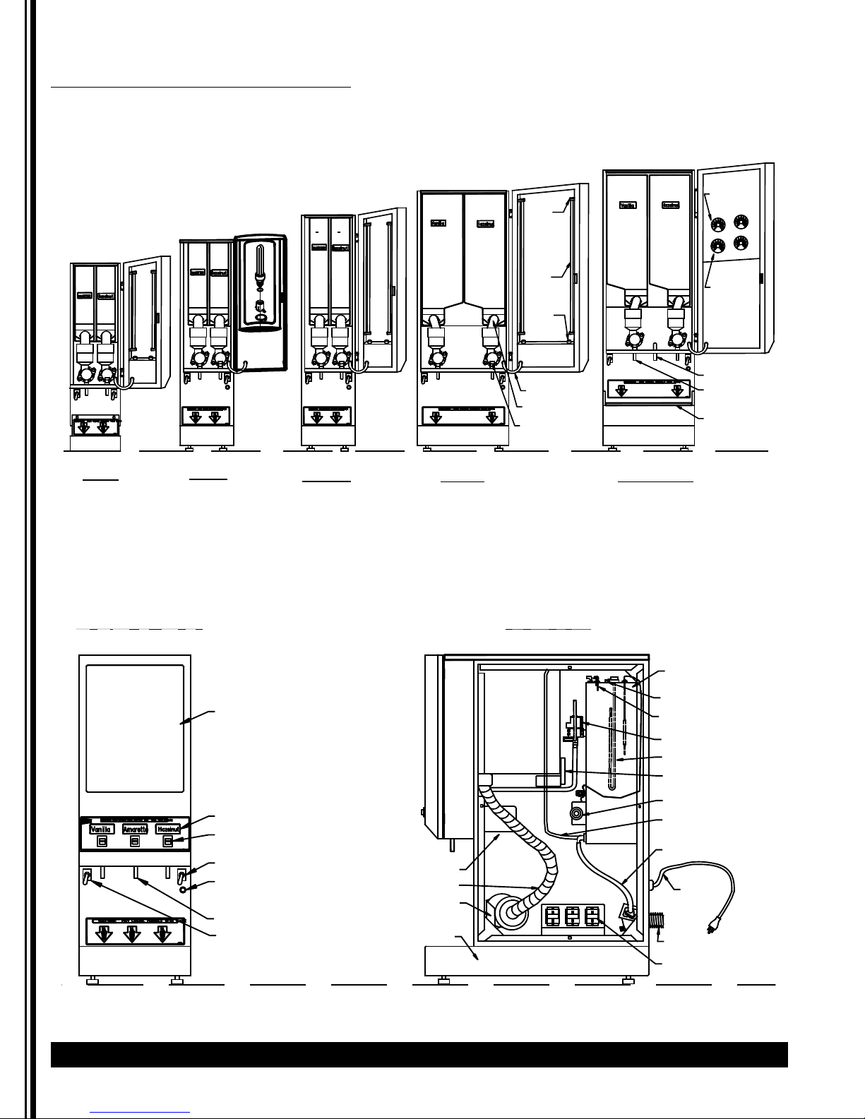
Description and Location of Components
Note: Refer to following illustration for description and location of COMPONENTS and CONTROLS.
Installation (continued)
4 lb. 4 lb.
14 lb.
14 lb.14 lb.
1
1
5
5
2 lb.
2 lb.
LAMP
SOCKET
14 lb.
GRAM THROW,
STRENTH
ADJUSTMENT
4 lb. 4 lb.
DRIP TRAY
GB2-LP
DRIP TRAY DRIP TRAY
2K- GB
FRONT VIEW GB3 SHOWN
DRIP TRAY
GB2M-5.5
GB2-SKI
LAMP
LAMP
STARTER
CORD SET
PRODUCT GUIDE
WHIP CHAMBER
RIGHT SIDE VIEW
DRIP TRAY
GB2-Super SKI
TANK ASS'Y
CUP SIZE,
VOLUME
ADJUSTMENT
HOT WATER SPOUT
CAPP. SPOUT [2]
SHELF
LABEL AREA
PRODUCT LABEL
DISPENSE BUTTON
POWER SWITCH
PILOT LIGHT FOR
HEATER
SPOUT
RINSE SWITCH
DRIP TRAY
WHIPPER MOTOR
BLOWER DUCT HOSE
FAN/BLOWER
DRIP TRAY
HI-LIMIT (TEMP)
WATER LEVEL CONTROL
DISPENSE VALVE
HEATER ASS'Y
AUGER MOTOR
THERMOSTAT
DRAIN HOSE W/PLUG
WATER INLET HOSE
POWER
CORD
WATER INLET VALVE
RELAY/TIMER
Page 5

GB Series Cecilware
®
5
Installation (continued)
1. HOPPERS: Depress the door latch on the left
side of the door and pull door open to access
the hoppers.
• The hoppers hold up to 14 lbs. (14 kg) of
Cappuccino product and up to 1.5 lbs. (0.7kg) of
freeze dried coffee product, depending on
model.
• To remove the hoppers swing the top
compartment door open and lift out the
hoppers.
• To reposition the hoppers in the
compartment, slide the hopper base back
between the rails until the 1/4" pin at the
bottom of the hopper base falls into the 1/4"
positioning hole of the compartment base
cover.
2. RINSE SWITCH: With the door open, the rinse
switch is located on the left side of the first
Whipper chamber.
• In the RINSE position, it disengages the
hopper motors and allows only water to be
dispensed.
• It is used for flushing out the Whipper
Chambers and to adjust the water dispense
valves for proper flow rates.
3. HEATER SWITCH: This switch is located inside
the cabinet behind the right hopper. Open door
and remove right hopper to access it.
• Its primary function is to shut off the heating
element during the initial priming, start-up
operation of the machine, or whenever the
tank is being drained for service.
Note: The Power Switch and Heater Switch must
be ON in order for the elements to operate.
4. POWER SWITCH: This switch is located on the
left side of the splash panel below the door. On
120V, 1.8 KW and 120/240 or 240V, 3 KW single
element machines the power switch controls all
power to the machine including the heater
elements.
Note: On 120/240V, 6 KW machines, the Power and
Heater Switches are independent of each other.
Both switches must be OFF in order for the
machine to be completely shut down.
5. WATER LEVEL CONTROLS: Under normal
conditions and operation, the water level in the
tank should not drop more than 1/2" (1.3cm)
from the probe. If it does, the tank is not
refilling fast enough. Check the water line and
water filter; they may need cleaning or
replacing.
1. Tank Control Board Part# 349-00012
(Export 240V Part# L706AL)
2. Water Inlet Valve Part# L462AL
(Export 240V Part# L426AL)
3. Water Level Sensor Part# K695QL
Start-up Procedure
NOTICE: Make sure that the Heater Switch, located
behind right hopper with door opened, is in the OFF
position.
1. Connect the 1/4" dia. copper waterline to the
1/4" flare water inlet fitting of the valve.
2. Plug the power cord(s) into a proper receptacle.
Note: GB8M10 units use two power cords. Each cord
must be plugged into a separate receptacle.
3. Activate the Power Switch (Toggle Up). The
door display panel, the red power indicator
light and the green dispense buttons will light
up and the tank will start filling. Allow
approximately 4-5 minutes for the tank to fill.
4. Activate the Heater Switch. Allow
approximately 10-30 minutes for the water to
reach a temperature of 190°F (88°C). The heat
up time will depend on the water inlet
temperature, the input voltage, and the
wattage of the elements in the machine.
5. Place a 8 oz. (240ml) or larger cup under the left
dispense nozzle, press and hold the left
dispense switch for 6 seconds. The machine will
dispense water at the rate of 1 oz. (30ml) per
second. Repeat it several times to check for
consistent output. Repeat same for the other
dispense switches. This procedure checks that
the dispense valves are not air-locked.
6. While the tank is heating, remove the hoppers,
load them with products, and reposition them
back in the machine. When the green ready
light comes on, the tank has reached its brew
temperature and the machine is ready to
dispense the first cup of Cappuccino.
Filling the Hoppers
1. To remove the hoppers, swing the top
compartment door open and lift out the
hoppers.
2. Fill each hopper with the correct product.
3. Reposition hoppers in the hopper
compartment, making sure the hoppers are
properly seated.
If you need help, call Grindmaster-Cecilware Technical
Service Department, (502) 425-4776 or (800) 695-4500
(USA & Canada only) 8 AM - 6 PM EST.
Prior authorization must be obtained from
Grindmaster-Cecilware for all warranty claims.
Page 6
6 Cecilware
®
GB Series
Your new powdered beverage dispenser is easy to
operate and maintain. Before you place it in service,
please have all personnel familiarize themselves with
these instructions. Keep this manual in a convenient
place for ready reference.
How to Operate
To dispense a cup of Cappuccino or Coffee:
• Place an 8 oz. (240ml) or larger cup under selected
drink dispense nozzle.
• For Manual units: Push and hold brew button until
cup is 2/3 full, then release button.
• For Automatic units: Press and Release button. Cup
will fill up automatically to its preset amount.
Adjustments
Water Flow Rate Adjustment
Adjust water flow rate to correct level in Whipping
Chamber.
The Dispense Valves are factory adjusted for a
maximum Flow Rate of 1 to 1.3 oz./sec (30-38 ml/sec).
[Approximate settings: 1.3 oz./sec (38 ml/sec) for
COFFEE and CAPPUCCINO]
Exceeding this Flow Rate will cause the Mixing Chamber
to overflow.
Note: To access the Water Dispense Valves, open door
and remove Hoppers.
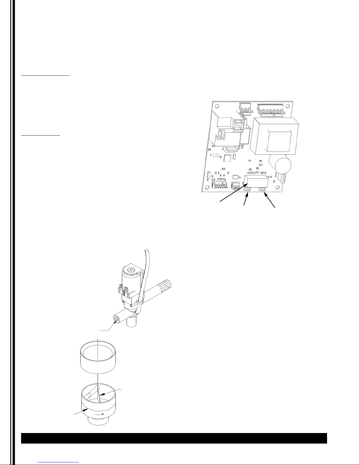
Temperature Adjustment (Tank Control Board
Type)
1. Locate the Tank Control Board.
2. Press button under right side of display to increase
temperature.
3. Press button under left side of display to decrease
temperature.
4. Pressing both buttons simultaneously will reset to
default 190°F (88°C).
Temperature Adjustment (Thermostat Type)
1. Locate Thermostat: Remove the right side panel.
Thermostat is mounted on side of tank.
The GB beverage dispensers are factory set to
deliver hot brewing water at 190°F (88°C) with the
thermostat knob turned to full ON position. If
adjustments should be necessary to increase or
decrease the water TEMPERATURE, proceed as
follows:
Note: Set the Rinse Switch to ON. This will disengage
the Hopper Motors when dispensing water for
Temperature measurements.
2. To INCREASE the water temperature - With the
Thermostat Knob to its maximum clockwise
position, remove the knob and locate the slotted
adjustment screw inside the hollow thermostat
shaft. Using a narrow-bladed screwdriver, engage
slotted adjustment screw and turn it ¼ turn slowly
counter-clockwise.
Allow a few minutes for the temperature to reach
set level. The Heater Light will go ON, indicating the
heating element is activated, wait for it to go OFF,
indicating that the water has reached new set
temperature. Take a temperature reading and
repeat if necessary.
3. To DECREASE the water temperature - simply turn
the Thermostat Knob one notch counter-clockwise
to the next lower dial setting.
Display
Decrease
Increase
190°
Operation
TO ADJUST WATER FLOW RATE:
1. Open door and remove
hoppers. Locate Dispense
Valve behind hoppers,
mounted on tank.
2. Locate adjustment screw on
Dispense Valve.
3. Using Allen Key or flat
screwdriver rotate, 1/4 turn at
a time,
CLOCKWISE to decrease water
flow, or
COUNTERCLOCKWISE to increase
water flow.
4. Check water flow output,
after each 1/4 turn.
WATER FLOW ADJUSTMENT
DISPENSE VALVE
DISPENSE CAP
Adjust Water Flow Rate so that the
water level reaches half way up in
the Mixing Chamber, as shown.
CORRECT WATER
LEVEL FOR MAX
FLOW RATE.
TRIANGULAR RIB
MIXING CHAMBER
Page 7

GB Series Cecilware
®
7
Operation (continued)
GB SKI SUPER - VOLUME AND PRODUCT STRENGTH ADJUSTMENTS
DRINK STRENGTH ADJUSTMENTS - by adjusting the Auger Speed.
I. UNITS WITH FIXED SPEED AUGER MOTORS-AC [CD150] - Fixed Auger Speed [95 RPM] and dispenses powder at a constant fixed rate.
Drink Strength adjustments can be made by adjusting the water flow rate on the Water Dispense Valves.
1. Remove Hoppers to access the Dispense Valve, located behind the hoppers.
2. Locate Flow Adjustment Screw on Dispense Valve.
3. Rotate adjustment screw Counterclockwise to INCREASE Flow Rate, Clockwise to DECREASE Flow Rate.
(Note:
the water flow rate should not exceed 1 to 1.3 oz./sec.)
Do not turn Adjustment Key more than 1/4 turn at a time without checking drink strength (ratio of water to powder).
II. UNITS WITH VARIABLE SPEED AUGER MOTORS-DC [CD151] - Variable Auger Speed [10 to 130 RPM]
Drink or Product Strength adjustments can be made by adjusting the Auger Motor RPM [knob on inside door panel],
which controls the amount of product being dispensed [gram throw]. The gram throw is factory preset at 7.
Because the consistency of each product varies, the customer can set the desired gram throw for each hopper.
The water flow rate on the Dispense Valves should remain fixed.
Note: the water flow rate should not exceed 1-1.3 oz./sec to avoid spi
DRINK SIZE ADJUSTMENTS
a. Manual Machines : Hold down the Dispense Button until desired amount is dispensed.
b. Automatic Machines with Timer L493A on Inside Door Panel NOT Programmable] & speed control
board L556A: To increase the volume, turn the dial to the next increment. [0-1 is equivalent to 2 sec.]
c. Automatic Machines with Programmable "Teach me"Timers [L576A or L582A]: These units do not
have a cup size adjustment knob inside the door, since the timer is programmab
llage from dispense chamber.
le from the dispense button.
PROGRAMMING FOR AUTOMATIC DISPENSE WITH BUZZER
1. Turn Power Switch ON (toggle switch inside door).
2. PRESS and HOLD [red] STOP Button with one hand.
3. PRESS and HOLD [green] DISPENSE Button with other hand.
4. RELEASE [red] STOP Button ONLY.
5. Continue to HOLD [green] DISPENSE Button until buzzer sounds
for (4 SEC. DELAY),
then RELEASE.
6. PRESS and RELEASE [green] DISPENSE Button. Product begins dispensing.
When it reaches the "DESIRED VOLUME",
7. PRESS and RELEASE [green] DISPENSE Button to SET "DESIRED VOLUME".
DISPENSE Button can be "jogged" to top off.
8. PRESS and RELEASE [red] STOP button to
LOCK IN "DESIRED VOLUME".
Repeat steps 1 to 8 for each Dispense Button.
PROGRAMMING INSTRUCTIONS FOR
1. PRESS AND HOLD STOP [red] BUTTON WITH ONE HAND.
2. PRESS AND HOLD DISPENSE [green] BUTTON WITH OTHER HAND.
MANUAL DISPENSE WITH BUZZER
S
T
O
P
3. RELEASE STOP [red] BUTTON.
4. CONTINUE TO HOLD [green] BUTTON AFTER BUZZER SOUNDS (4 SEC. DELAY).
5. RELEASE DISPENSE [green] BUTTON.
6. PRESS AND RELEASE STOP [red] BUTTON
.
H
O
T
W
AT
E
R
7. YOU ARE READY FOR MANUAL DISPENSE.
The Total Time The Water Is Running Is Accumulated And Saved Into Memory. For Normal Operation,
Press and Release Dispense Button.
The Timers Have Been Factory Preset for 6 oz. Cups for Coffee; For 8 oz. Cups for Soup and Cappuccino.
To Change
TO CHECK VOLUME AND GRAM THROW DISPENSED
To Larger Or Smaller Cup Sizes [Volumes] Repeat Steps 1 To 8 Above.
(ratio):
1. Remove the product guide from the hopper and position a receptacle under the hopper nozzle to catch the gram throw of product.
Also place a measuring cup under extension tube to catch the water dispensed.
2. Push the dispense button and check the amount of product
dispensed, amount of water dispensed, and time [use stop watch] to dispense that water.
3. The amount of of water dispensed in the measuring cup divided by the amount of time to dispense that water is the Water Flow Rate from Dispense
Valve.
FOR CAPPUCCINO: The machine is factory adjusted to
dispense 4-4.5 gr./sec. per OZ. Cup. [32 grams Product per 8 oz. cup]
The recommended throw is 28-32 grams per 8 oz. cup for Cappuccino, with 80% fill.
FOR COFFEE: The machine is factory adjusted to dispense 0.3 gr./sec per OZ. Cup. [1.5 grams of coffee product per 5 oz. of liquid (in a 6 oz. cup).
The recommended throw is 1.5 to 1.8 grams per 6 oz. cup of Coffee, with 80% fill.
Page 8
8 Cecilware
®
GB Series
NOTICE: All sanitizing agents in the food zone must
comply with 21 CFR 178.1010.
Sanitize all food dispensing units periodically. All parts
to be sanitized must be cleaned first. Cleaning and
sanitizing frequency must follow state and local health
department regulations.
Daily maintenance:
1. Rinse whipper chambers
• Position a container under dispense tubes.
• Move rinse switch to "rinse".
• Push and hold each dispense button 3 to 5 sec.
• Move rinse switch to "serve".
Note: On manual dispense machines, push and hold the
dispense buttons for 10 seconds.
2. Empty drip tray, wash, rinse, and sanitize.
3. The outside of the machine can be cleaned with
warm soapy water and a damp cloth.
Weekly maintenance:
1. Product hopper cleaning
• Rotate product guides up, remove hoppers from
machine.
• Empty powder into pans.
• Pull off product guides.
• Remove agitator wheels.
• Unscrew and remove front and back auger locks.
• Remove auger.
• Wash, rinse, sanitize, and air dry all small parts.
• Wash & scrub hoppers and agitator wheel recesses
with bristle brush. Rinse, sanitize, and allow to air
dry.
• Reassemble all hoppers.
• Pour powder into hoppers.
• Install all hoppers into unit.
2. Whipper chamber cleaning
• Remove dispense caps by turning and lifting.
• Remove mixing bowls by lifting and pulling.
• Remove product tubes by pulling down.
• Twist off whipping chambers clockwise.
• Pull off whipper blades.
• Twist off whipper chamber mounts clockwise.
• Remove O-rings.
• Remove tray by pulling levers down.
• Remove both powder trays by pulling levers out.
• Wash, rinse, and sanitize small parts and interior
machine surfaces.
• Reassemble all small parts.
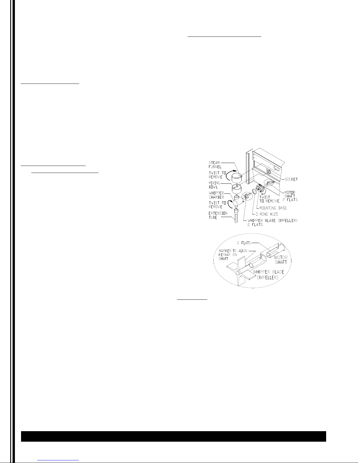
Note: When reassembling, align flat keyway inside
blade with flat keyway of motor shaft. Push the
whipper blade all the way on.
Sanitizing
1. Prepare a sanitizing solution in accordance with
local health department regulations. You may also
refer to the US Food and Drug Administration
regulation 21 CFR 178.1010 “Sanitizing Solutions”
and US Environmental Protection Agency 40 CFR
18.940 “Tolerance exemptions for active and inert
ingredients for use in antimicrobial formulations
(Food-contact surface sanitizing solutions)”.
2 Follow the instructions provided with the sanitizing
agent.
3 Let all sanitized parts drain and air dry. DO NOT
WIPE THEM DRY.
Cleaning
Page 9
GB Series Cecilware
®
9
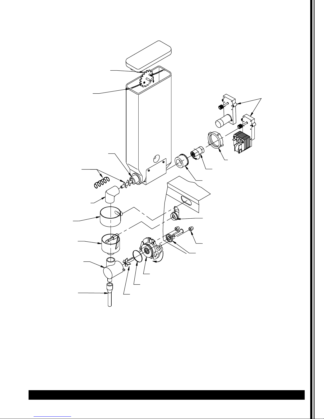
Cleaning (continued)
AGITATOR GEAR
AGITATOR WIRE
AUGER BUSHING FRONT
AUGER
PRODUCT GUIDE
DISPENSE CUP
MIXING CHAMBER
AUGER MOTOR
NUT [2]
FLANGE/ NUT
AUGER BUSHING-BACK
MIX BOWL SOCKET
BASE MOUNT GROMMET
WHIPPER CHAMBER
TWIST TO REMOVE
MOUNTING BASE
'O'-RING #
EXTENSION TUBE
WHIPPER BLADE
125
SLINGER DISC
Page 10
Maintenance
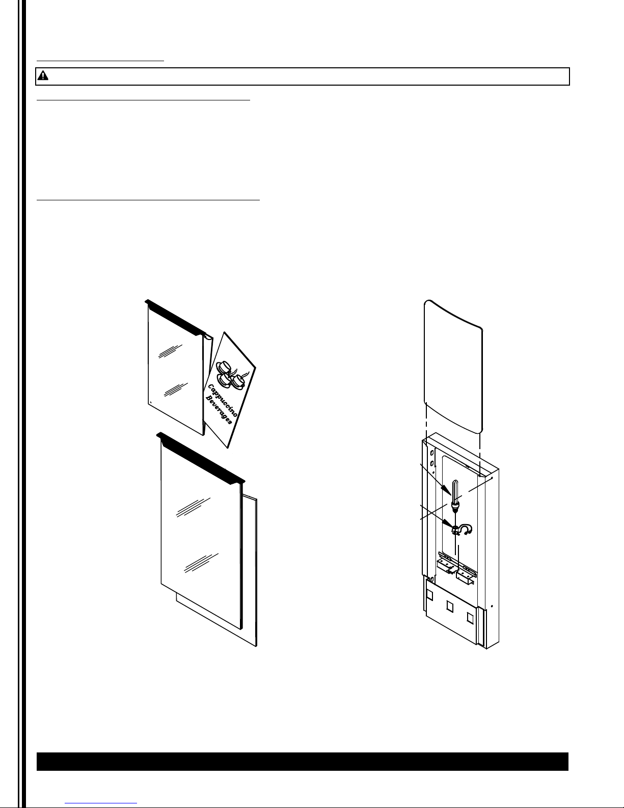
Lit Display Replacement
WARNING Riskof electrical shock. Turn off power to unit before replacing bulb or starter.
To replace the picture inside metal door:
Lift up the two end tabs on top of door with a pointed object or flat head screwdriver.
Pull the entire picture frame out. Open up the two clear panels and replace picture.
Tuck clear plastic panel inside bracket at top.
Be sure to tuck clear panel under bracket before sliding frame assembly inside door.
The longer metal tab side goes in the front.
To replace the picture inside molded door:
Remove molded door front by removing side screws. Slide out clear plastic panel with picture.
Replace picture and slide the plastic panel w/ new picture into the door frame. Then put front molded door back
on with screws on the sides.
10 Cecilware
®
GB Series
c
To repla
T
C
U
D
P
O
R
E
L
B
L
A
T
C
U
D
P
O
R
E
L
L
A
B
Page 11
GB Series Cecilware
®
11
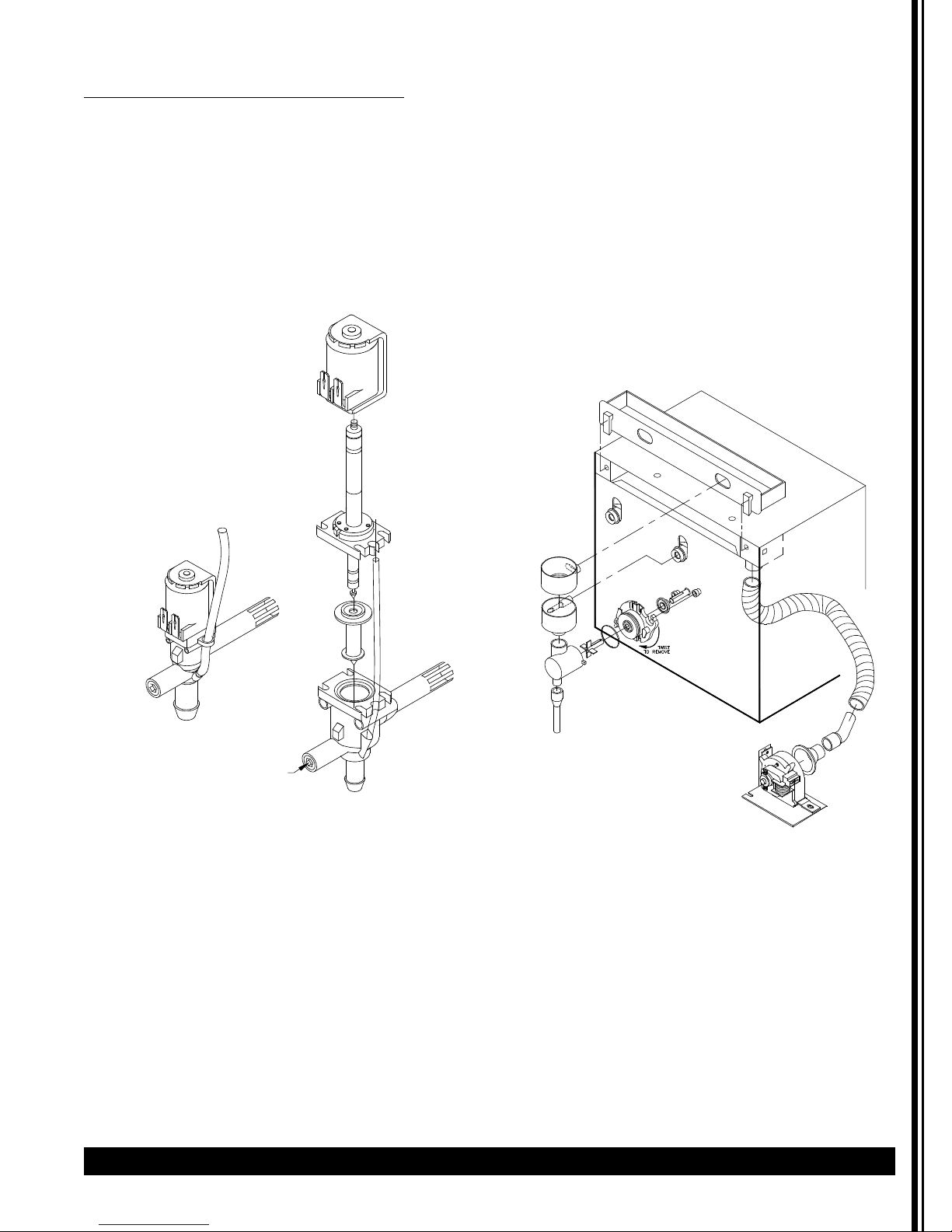
Recommended preventive maintenance
1) Dispense Valves
• Check all dispense valves for lime build-up.
• Drain the water tank to just below the level of
the dispense valves.
• Remove the valves and clean. (Take these valves
apart byhand as shown).
• Replace the assembly as needed (L467AL -120V
or L676AL - 230V import).
• Replace the valve into the tank and refill tank.
• Repair Kit M491QL.
2) • Check all chamber mounts for signs of wear:
• Product runningdown the front of the unit.
• Product built up on the back of chamber
mount.
• Remove chamber mount.
• Clean and re-lubricate motor shaft using food
grade lubricant only.
• Replace with new chamber mount.
3) • Clean out vent motor, trough, and tubing.
• Lift up black tabs, remove trough drawer.
• Clean and replace trough drawer.
• Remove hose assembly from the motor.
• Clean out and replace hose.
Maintenance (continued)
Dispense Valve
Chamber Mount
WATER FLOW ADJUSTMENT
Page 12

Component Tests
Dual Probe Test
If lack of water persists, check the probe as follows:
1. Turn on the power and water supply.
2. Check inside the tank to make sure the water is
below the Probe.
3. Pull the BLUE wire and terminal OFF the Probe rod.
If water still does not flow after the wire is
disconnected from the Probe, the problem may be
in the Tank Control Board.
4. If water starts flowing into the tank, the Probe may
be grounded, due to excessive liming. Check with
Ohm meter. Clean probe.
Water Inlet Valve Test
1. Turn power OFF. If the water level rises inside a
partially filled tank, the Water Inlet Valve is leaking.
2. Disconnect wires from the Water Inlet Valve coil and
connect a 2 wire line cord to the terminals. Plug it
into a 115V outlet. If water flows in and stops when
you pull it out, the Valve is working correctly.
Repeat this test a few times. The problem may be
in the Probe or Water Level Control Board.
3. If the water does not flow in when the cord is
plugged into an electrical outlet, the Solenoid coil
may be damaged, opened or the valve may have an
obstruction preventing the water from flowing in.
Clean or replace it.
Out of Product Sensor Test
1. Remove Hopper from cabinet, place the palm of
your hand up against the 1 inch diameter round
sensor at the back of the hopper chamber.
2. Listen for relay clicking on and off as you move your
hand towards and away from the sensor.
3 If relay clicks, system is operating OK.
4 Replace with a full hopper and listen for the relay
click.
5 If all this checks out and the out of product light
does not go off, then there must be defective
wiring. See wiring diagram.
Dual Probe Liquid Level Controller Test
(For models manufactured 2015 and prior)
Check the Controller as follows:
1. Make sure there is power input to the Controller at
the terminals AC1 & AC2
Your voltmeter should read 115 Volts. It should read
the same at terminals AC1 & FILL when the water
level is low. This is the output power to actuate the
coil of the Solenoid Valve to open it. The lack of
voltage at terminals AC1 & L-LEVEL or H-LEVEL
indicates that the Controller is not working
properly.
2. Make sure all wire connections are tight, including
ground.
3. If after this, the Controller is still failing to open the
Water Inlet Valve, replace it.
12 Cecilware
®
GB Series
Maintenance (continued)
BLUE
DUAL
PROBE
OUT OF PRODUCT
HOSE NUT ASSY
SENSOR
DUAL PROBE LIQUID LEVEL
CONTROLLER
TO
N
SOLENOID
TO PROBE
L1
WATER INLET VALVE
GROUNDING
PLATE IN
BACK OF THE
BOARD
GROUND
TERMINAL
SS WATER LEVEL CONTROL CCA
4
T5
SINGLE L398C [120V]
DUAL L690A [120V]
SINGLE L399C [220V]
DUAL L706A [220V]
1
2
3
Page 13

GB Series Cecilware
®
13
Troubleshooting Guide
Before you call for help, please read the following:
Problem Possible Cause Solution
Merchandiser Display not lit.
No power.
Dispensing unit unplugged. Reconnect dispensing unit.
No power from Terminal Block. Check the Terminal Block for loose wire.
Defective light assembly. Replace LED board.
No water when Rinse Switch
is ON.
Water supply OFF. Turn water ON.
Clogged inlet screen (Water Inlet
Valve).
Disconnect water line and clean inlet
screen.
Inoperative Water Inlet Valve. Check connection, if needed replace
Valve.
Loose electrical connection. Check all electrical connections.
No product when Dispense
Button is pressed.
No product in Hopper. Add product.
Auger not working. Engage Hopper/Nut to Motor Gear
(See pg 9).
Damaged, loose, or missing Agitator
Gear.
Replace Agitator Gear (See pg 9).
Inoperative Auger Motor or Relay. Check connections of Motor, Relay, and/or
Switch; if needed replace components.
Hopper outlet clogged. Clean Hopper and check Cartridge Heater.
Faulty Coupling. Replace damaged Coupling components.
Water does not shut off.
Water keeps dispensing.
Leaking Water Inlet Valve. Clean/check fittings of Water Inlet Valve.
Replace Water Inlet Valve if needed. See
Water Inlet Valve Test.
Inoperative Dispense Switch. Check Switch connections. Replace
Dispense Switch if needed.
Inoperative Rinse Switch. Check Rinse Switch connections.
Replace Rinse Switch if inoperative.
Clogged/stuck Water Dispense Valve. Clean or unclog Water Dispense Valve.
Replace Dispense Valve if inoperative.
No water is going into tank at
all.
Water Inlet Valve malfunction. Check Solenoid. Replace if necessary.
See Water Inlet Valve Test.
Water Level Sensor/ Probe malfunction. Check Probe. Replace if necessary. See
Dual Probe Test.
Solid State Level Control Board. Check Water Level Controls. Replace if
necessary. See Dual Probe Liquid
Level Controller Test.
Water will not stop flowing
into water tank.
Water Level Probe malfunction. Check Probe. Replace if necessary. See
Dual Probe Test.
Solenoid (Water Inlet Valve)
malfunction.
Check Solenoid. Replace if necessary. See
Water Inlet Valve Test.
Solid State Water Level Control
malfunction.
Check the Water Level Controls. Replace if
necessary. See Dual Probe Liquid Level
Controller Test.
Water is not heating up in the
water tank.
Heater Switch is OFF. Turn Heater Switch ON.
Thermostat is OFF. (Only models with
separate Thermostat)
Turn Thermostat ON. Turn Knob
Clockwise.
Loose connection on Thermostat. Make sure all wires and terminals on
Thermostat are tight.
Hi-Limit Temperature Switch is
defective.
Replace the Hi-limit.
Heater is burned out or defective. Replace the Heater.
WARNING: To reduce the risk of electrical shock, unplug the dispenser power cord before repairing or
replacing any internal components of the unit. Before any attempt to replace a component, be sure to check all
electrical connections for proper contact.
Page 14

Troubleshooting Guide (continued)
If you still need help, call Grindmaster-Cecilware Technical Service Department, (502) 425-4776 or (800) 695-4500
option 2 (USA & Canada only) (Monday through Friday 8 AM - 6 PM EST). Please have the model and serial number
ready so that accurate information can be given.
Prior authorization must be obtained from Grindmaster-Cecilware for all warranty claims.
Grindmaster-Cecilware provides the industry’s BEST warranty. Visit our website at GMCW.com for
warranty terms and conditions.
14 Cecilware
®
GB Series
Page 15

GB Series Cecilware
®
15
Parts Diagram and List
Hopper Illustrations
CD65X - ORANGE GROMMET
HOPPER ASS'Y CD104, 7 LB, 18" HEIGHT x 3"W, W/NYLON AUGER
HOPPER ASS'Y CD120, 5.5 LB, 14" HEIGHT x 3"W, W/NYLON AUGER
HOPPER ASS'Y CD68A, 4 LB, 11.5" HEIGHT x 3"W, W/NYL
HOPPER ASS'Y CD313, 1 LB COFFEE, 7.875" HEIGHT x 3"W, W/NYLON AUGER
HOPPER COVER CD106
AGITATOR GEAR CD117
Agitator Gear with wire CD256
Agitator Gear with spring CD182
AGITATOR WIRE
HOPPER CD104
HOPPER CD120
HOPPER CD68A
HOPPER CD313
AUGER BUSHING FRONT CD277
NYLON AUGER
(22.5Øx18mmPT)
W/"O" RING CD139
PRODUCT GUIDE CD70A
DISPENSE CUP
CD61A-white / CD272-black
MIXING CHAMBER
CD137-white / CD275 black
WHIPPER CHAMBER
STRAIGHT CD63A-white
STRAIGHT CD316-black
SLANTED CD362-wh
EXTENSION TUBE
M467A - white
H306A-stainless steel
CD130
TWIST TO REMOVE
ite
MOUNTING BASE CD65A-white / CD317-black
M379A 'O'-RING #125
WHIPPER BLADE CD64A
ON AUGER
AUGER MOTOR
CD175 90rpm AC
CD87A 44rpm AC (COFFEE)
CD151 90rpm DC (Portion Control)
NUT [2] CD278
FLANGE/ NUT CD271
AUGER BUSHING-BACK CD279
MIX BOWL SOCKET CD67A
CD67A W/O-RING M378A CD100
W/O-R
ING M480A
BASE MOUNT GROMMET CD66A
SLINGER DISC CD124
HOPPER ASS'Y CD105 (14 lb; 18" HEIGHT X 6.25"SQ) W/NYLON AUGER
HOPPER ASS'Y CD99A (8 lb; 11.5" HEIGHT
COVER CD160
AGITATOR CD14 1
HOPPER CD105
HOPPER CD99A
AUGER BUSHING FRONT CD102
WITH 0-RING CD103
NYLON AUGER CD130
(22.5Øx18mmPT)
W/"O" RING CD139
PRODUCT GUIDE CD70A
DISPENSE CUP
CD61A-white / CD272-black
MIXING CHAMBER
CD137-white / CD275 black
WHIPPER CHAMBER
STRAIGHT CD63A-white
STRAIGHT CD316-black
SLANTED CD362-wh
EXTENSION TUBE
M467A - white
H306A-stainless steel
ite
M379A 'O'-RING #125
WHIPPER BLADE CD143 or CD64A
X 6.25"SQ) W/NYLON AUGER
AUGER MOTOR
CD175 90rpm AC
CD87A 44rpm AC (COFFEE)
CD151 90rpm DC (Portion Control)
AUGER BUSHING-BACK CD279
MIX BOWL SOCKET CD67A
CD67A W/O-RING M378A CD100
W/O-RING M480A
BASE MOUNT GROMMET CD66A
SLINGER DISC CD124
TWIST TO REMOVE
MOUNTING BASE CD65A-white / CD317-black
NUT [2] CD278
FLANGE/ NUT CD271
HOPPER ASS'Y CD338, 5 LB, 14"HEIGHT x 2.5"W, W/NYLON AUGER HOPPER
ASS'Y CD339, 4 LB, 12.5"HEIGHT x 2.5"W, W/NYLON AUGER
HOPPER COVER CD187
AGITATOR GEAR CD117
Agitator Gear with wire CD256
Agitator Gear with spring CD182
AGITATOR WIRE
HOPPER CD338
HOPPER CD339
AUGER BUSHING-FRONT CD277
NYLON AUGER CD130
(22.5Øx18mmPT)
W/"O" RING CD139
PRODUCT GUIDE CD70A
DISPENSE CUP CD61A
MIXING CHAM. CD137
WHIPPER CHAMBER
STRAIGHT CD63A-white
STRAIGHT CD316-black
SLANTED CD362-white
EXTENSION TUBE M467A
MOUNTING BASE CD65A
M379A 'O'-RING #125
WHIPPER BLADE CD64A
AUGER MOTOR
CD175 90rpm AC
CD87A 44rpm AC (COFFEE)
CD151 90rpm DC (Portion Control)
AUGER BUSHING-BACK CD279
MIX BOWL SOCKET CD67A
CD67A W/O-RING M378A CD100
W/O-RING M480A
BASE MOUNT GROMMET CD66A
SLINGER DISC CD124
TWIST TO REMOVE
NUT [2] CD278
FLANGE/ NUT CD271
P - HOPPER ASS'Y CD308 LT & CD309 RT 10 LB, 14"H, W/NYLON AUGER
P - HOPPER ASS'Y CD177 LT & CD178 RT 8 LB, 11.5"H, W/NYLON AUGER
HOPPER COVER
AGITATOR GEAR CD117
Agitator Gear with wire CD256
Agitator Gear with spring CD182
AGITATOR WIRE
HOPPER CD308 Left shown
HOPPER CD177 Left shown
AUGER BUSHING FRONT CD277
NYLON AUGER CD130
(22.5Øx18mmPT)
W/"O" RING CD139
PRODUCT GUIDE CD70A
DISPENSE CUP
CD61A-white / CD272-black
MIXING CHAM. CD137
WHIPPER CHAMBER
STRAIGHT CD63A-white
STRAIGHT CD316-black
SLANTED CD362-white
EXTENSION TUBE
M467A - white
H306A-stainless steel
MOUNTING BASE CD65A-white / CD317-black
M379A 'O'-RING #125
WHIPPER BLADE CD64A
AUGER MOTOR
CD175 90rpm AC
CD87A 44rpm AC (COFFEE)
CD151 90rpm DC (Portion Control)
AUGER BUSHING-BACK CD279
MIX BOWL SOCKET CD67A
CD67A W/O-RING M378A
CD100 W
BASE MOUNT GROMMET CD66A
SLINGER DISC CD124
TWIST TO REMOVE
NUT [2] CD278
FLANGE/ NUT CD271
/O-RING M480A
Page 16

16 Cecilware
®
GB Series
Parts Diagram and List (continued)
Hopper Illustrations
HOPPER ASS'Y CD144, 5.5 LB, 14"Hx 3"W, W/WIRE AUGER CD101
HOPPER ASS'Y CD152, 4 LB, 11.5"H x 3"W, W/WIRE AUGER CD101
HOPPER ASS'Y CD98A, 4 LB, 11.5"H x 3"W, W/WIRE AUGER CD74A or CD153
HOPPER COVER CD106
AGITATOR GEAR
CD117 [W/CD101]
CD97A [W/ CD153A or CD74A]
CD320 [coffee W/ CD74A]
AGITATOR WIRE
HOPPER CD144
HOPPER CD152
HOPPER CD98A
AUGER BUSHING-FRONT CD277
CD306 [W/CD74 & CD153]
WIRE AUGER
CD101 (22.5Øx18mmPT)
CD74A (17Øx12mmPT)
CD153 (17Øx9mmPT)
PRODUCT GUIDE CD70A
DISPENSE CUP CD61A
MIXING CHAM. CD137
WHIPPER CHAMBER
STRAIGHT CD63A-white
STRAIGHT CD316-black
SLANTED CD362-white
EXTENSION TUBE M467A
TWIST TO REMOVE
MOUNTING BASE CD65A
M379A 'O'-RING #125
WHIPPER BLADE CD143 or CD64A
DC MOTOR CD151 90rpm
(Portion Control)
NUT [2] CD278
FLANGE/ NUT CD271
AUGER BUSHING-BACK CD279
MIX BOWL SOCKET CD67A
CD67A W/O-RING M378A
CD100 W/O-RING M480A
BASE MOUNT GROMMET CD66A
SLINGER DISC CD124
HOPPER ASS'Y CD163 (14 l
b; 18" HEIGHT X 6.25"SQ) W/WIRE AUGER
HOPPER ASS'Y CD162 (11 lb; 14" HEIGHT X 6.25"SQ) W/WIRE AUGER
HOPPER ASS'Y CD161 (8 lb; 11.5" HEIGHT X 6.25"SQ) W/WIRE AUGER
COVER CD160
HOPPER CD163
HOPPER CD162
HOPPER CD161
AUGER BUSHING-FRONT CD102
W/"O" RING CD103
W
IRE AUGER
CD101 (22.5Øx18mmPT)
CD74A (17Øx12mmPT)
CD153 (17Øx9mmPT)
PRODUCT GUIDE
DISPENSE CUP CD61A
MIXING CHAM. CD137
WHIPPER CHAMBER
STRAIGHT CD63A-white
STRA
SLANTED CD362-white
EXTENSION TUBE M467A
CD70A
IGHT CD316-black
TWIST TO REMOVE
MOUNTING BASE CD65A
M379A 'O'-RING #125
WHIPPER BLADE CD143 or CD64A
DC MOTOR CD151 90rpm
(Portion Control)
AUGER BUSHING-BACK CD279
MIX BOWL SOCKET CD67A
CD67A W/O-RING M378A
CD100 W/O-RING M480A
BASE MOUNT GROMMET CD66A
SLINGER DISC CD124
AGITATOR CD14 1
NUT [2] CD278
FLANGE/ NUT CD271
HOPPER ASS'Y CD185, 5 LB, 14"HEIGHT
HOPPER ASS'Y CD155, 4 LB, 12.5"HEIGHT x 2.5"W, W/WIRE AUGER
HOPPER COVER CD187
AGITATOR GEAR
CD117 [W/ CD101]
CD97 [W/ CD153 OR CD74A]
CD320 [coffee W/ CD74A]
AGITATOR WIRE
HOPPER CD185
HOPPER CD155
AUGER BUSHING-FRONT CD277
WIRE AUGER CD101
(22.5Øx18mmPT)
PRODUCT GUIDE CD70A
DISPENSE CUP CD61A
MIXING CHAM. CD137
WHIPPER CHAMBER
STRAIGHT CD63A-white
STRAIGHT CD316-black
SLANTED CD362-white
EXTENSION TUBE M467A
TWIST TO REMOVE
MOUNTING BASE CD65A
M379A 'O'-RING #125
WHIPPER BLADE CD64A
x 2.5"W, W/WIRE AUGER
MOTOR CD151 DC 90rpm
(Portion Control)
NUT [2] CD278
FLANGE/ NUT CD271
AUGER BUSHING-BACK CD279
MIX BOWL SOCKET CD67A
CD67A W/O-RING M378A
CD100 W/O-RING M480A
BASE MOUNT GROMMET CD66A
SLINGER DISC CD124
P - HOPPER ASS'Y CD179 (LEFT) CD180 (RIGHT) 10 LB,
HOPPER COVER
AGITATOR GEAR
CD117 [W/ CD101]
CD97 [W/ CD153 OR CD74A]
CD320 [coffee W/ CD74A]
AGITATOR WIRE
HOPPER CD179 Left shown
AUGER BUSHING
FRONT CD277
WIRE AUGER
CD149 (22.5Ø x 24.8mmPT)
CD74A coffee (17Øx18mmPT)
PRODUCT GUIDE CD70A
DISPENSE CUP CD61A
MIXING CHAM. CD137
WHIPPER CHAMBER
STRAIGHT CD63A-white
STRAIGHT CD316-black
SLANTED CD362-white
EXTENSION TUBE M467A
14"HEIGHT, W/WIRE AUGER
MOTOR CD151 DC 90rpm
(Portion Control)
NUT [2] CD278
FLANGE/ NUT CD271
AUGER BUSHING-BACK CD279
MIX BOWL SOCKET CD67A
CD67A W/O-RING M378A
CD100 W/O-RING M480A
BASE MOUNT GROMMET CD66A
SLINGER DISC CD124
TWIST TO REMOVE
MOUNTING BASE CD65A
M379A 'O'-RING #125
WHIPPER BLADE CD64A
Page 17

GB Series Cecilware
®
17
Parts Diagram and List (continued)
Tank Assembly
Page 18

Parts Diagram and List (continued)
Unit Assembly (GB3M shown)
18 Cecilware
®
GB Series
*See Metal Parts List
F
F
A
C
E
D
/
E
E
F
F
O
C
T
N
A
O
T
S
S
S
N
E
I
R
P
S
E
T
D
N
A
T
S
N
I
N
O
F
F
O
R
E
T
A
E
H
N
O
R
E
W
O
e
s
n
i
R
e
v
r
e
S
P
CCW
CCW
CCW
Page 19

GB Series Cecilware
®
19
*See Metal Parts List
Parts Diagram and List (continued)
Unit Assembly (GB2 SKI-SUPER shown)
T
O
H
R
E
T
A
W
CCW
CCW
CCW
Page 20

20 Cecilware
®
GB Series
Parts Diagram and List (continued)
Parts List
ITEM DESCRIPTION GB-LP GBK
GBM
GBM-5.5
GB-SKI
GB-SUPER-SKI w/
TEACH-ME TIMERS
GB6
1 TANK ASS’Y/TANK TOP ASS’Y - SEE METAL PARTS LIST - NEXT PAGE
ßßßß ß ß
2 SILICONE HOSE [BREATHER FITTING] [ .375 I.D x 32”] M326A M326AL M326AL M326AL M326AL M326AL M326AL
3 SILICONE HOSE [DISPENSE VALVE] [ .313 I.D x 14.5”] M324A M324AL M324AL M324AL M324AL M324AL M324AL
4 SILICONE HOSE [WATER INLET] [.375 I.D. x 13”] M326A M326AL M326AL M326AL M326AL M326AL M326AL
5 CHECK VALVE [PREVENTS BACKFLOW] [suggested – not supplied] L463AL L463AL L463AL L463AL L463AL L463AL
6 HOSE NUT ASS’Y OR FITTING 359-00098 - - - 359-00029 7 WATER INLET VALVE 120V (230V, 50HZ USE L426AL) CD257 L462AL L462AL L462AL L022A L462AL
8 FUSE HOLDER (120/240V ONLY) - - - - C396AL -
9 BUSSMAN SC25 FUSE (GB'S 120/240V ONLY) - - - - CE181 10 POWER CORD (230V, 50 HZ USE C112AL) C032SL C032SL C032SL C032SL C032SL C032SL
11 TERMINAL BLOCK FOR 120V [WAS B117A] [FOR 240V USE B116A] 60105 - - - B157AL 60112CWL
12 RELAY CONTROL GB5M, 5K, GB6 L533AL L533AL - - L533AL
13 TANK CONTROL BOARD 349-00012 (FOR 230V 50HZ USE L706AL)
ßßßß ß ß
13
[PRIOR TO 10/15 - DUAL WATER LEVEL CONTROL BOARD
USE L690AL - 120V & L706A - 220V)
13
[older SINGLE WATER LEVEL CONTROL BOARD
L398A - 120V & L399A - 220V]
14 STEPDOWN TRANSFORMER (240/120V only) - - - - CE187L 15 SPEED CONTROL BOARD [Controls Auger Speed GRAM THROW] - - - - L556AL 16 TRANSFORMER [use w/DC motor & Speed Control CCA] - - - - CF29AL 17 RELAY, OMRON B129AL B129AL B129AL B129AL B129AL B129AL
18 FAN CD56AL & ELBOW INSERT CD108 [USE FOR GB1, 1SKI, 2, 3, 6 ONLY]
ß ß ß ß ß ß
FAN CD224L w/ RW31Q Fan Housing Ass’y [GB4, 5, 2SKI ]
FAN CD166L [230V 50HZ ]
19 DUCT HOSE [for Exhaust Fan] CA214L CA214L CA214L CA214L CA214L CA214L
20 3/4" FEET (SET OF 4) M042AL M042AL M042AL M042AL M042AL M042AL
21 RINSE SWITCH [GB1, GB5 & GB6-L069AL; GB2-L299AL;
ßßßß ß ß
GB3-L446AL; GB4 L470AL]
22 POWER SWITCH & HEATER SWITCH (120V) OR [FOR 120/240V USE L299A] L069AL L069AL L069AL L069AL L069AL L069AL
23 HEATER INDICATOR LIGHT (amber C002AL, red C165AL) Use C072AL for GB1MLD C002AL C002AL C002AL C002AL C002AL C165AL
24 GRILL - SEE METAL PARTS LIST - NEXT PAGE
ß ß ß ß ß ß
25 DRIP TRAY - SEE METAL PARTS LIST - NEXT PAGE
ßßßß ß ß
26 WHIPPER MOTOR-short shaft (ONE PER HOPPER) CD350L CD350L CD350L CD350L CD350L CD350L
(240V- CD399L) (old style CD75AL)
27 SLINGER DISC (ONE PER HOPPER) CD124L CD124L CD124L CD124L CD124L CD124L
28 GROMMET CHAMBER MOUNTING (TWO PER HOPPER) CD66AL CD66AL CD66AL CD66AL CD66AL CD66AL
29 CHAMBER MOUNT (ONE PER HOPPER) CD65AL CD65AL CD65AL CD65AL CD65AL CD65AL
30 “O” RING # 125 (used w/ grommet CD66AL) M379A M379A
31 WHIP BLADE (old style used CD64AL) (ONE PER HOPPER) CD353L CD353L CD353L CD353L CD353L CD353L
32 EXTENSION TUBE PLASTIC (ONE PER HOPPER) M467AL M467AL M467AL M467AL M467AL M467AL
33 WHIP CHAMBER (Straight – CD63AL) OR (Slanted – CD362L) CD63AL
ßß
CD362L CD63AL CD362L
(ONE PER HOPPER)
34 MIXING CHAMBER [ALTERNATE CD62AL W/ RECTANGULAR WING] CD137L CD137L CD137L CD137L CD137L CD137L
(ONE PER HOPPER)
35 DISPENSE CAP OR SPLASH GUARD (ONE PER HOPPER) CD61AL CD61AL CD61AL CD61AL CD61AL CD61AL
36 “O” RING (#110) (used w/socket CD67A) M378A M378A
37 MIXING BOWL SOCKET (ONE PER HOPPER) CD67AL CD67AL CD67AL CD67AL CD67AL CD67AL
38 DISPENSE BUTTON (GB L455A) / (GB Ski Super L584A) STOP SWITCH L455AL L455AL L455AL L455AL L584AL L455AL
39-43 REPLACE WITH DOOR LIGHTING ASSEMBLY
ßßßß ß ß
234-00131 – LIGHTING ASSEMBLY, DOOR, GB1MLP/2LP
234-00132 – LIGHTING ASSEMBLY, DOOR, GB3LP/OATMEAL
234-00133 – LIGHTING ASSEMBLY, DOOR, GB3M5.5/10
234-00134 – LIGHTING ASSEMBLY, DOOR, GB4M5.5/GB5M10
44 DOOR LATCH 61234 U008AL M705AL M705AL 61234 M705AL
45 DOOR ASS’Y - SEE METAL PARTS LIST - NEXT PAGE
ßßßß ß ß
46
CLEANING INSTRUCTIONS N978AL NQ28AL N978AL N978AL N978AL N978AL
PROGRAMMING INSTRUCTIONS - - - - NF58AL -
47
TIMER “TEACH ME” [PROGRAM. dispense Time/Cup Size]-Single - - - - L576AL -
[Triple L582A] or TIMER [NOT PROGRAM.] - - - - - -
[use w/pot. L577A & dial/cup size labels: NF32A/33A/34A]
48
POTENTIOMETER - USED W/SPEED CONTROL BD [GRAM THROW DIAL] - - - - L557AL
-
LABEL, GRAM THROW DIAL- [GB2 NF30A; GB3 ND81A; GB4 NF31A] - - - - NF30AL
49 PRODUCT GUIDE (CHUTE) GB1SKI use , GB2SKI use CD234L CD70AL CD70AL CD70AL
ß
CD70AL CD70AL
50
HOPPER ASS’Y WITH COVER [w/NYLON auger] OR CD68AL -
ß
CD105L CD105L
CD180L
& CD185L
HOPPER ASS’Y WITH COVER [w/WIRE auger] (GB1M and GB1HC use CD99AL;
GBM5.5 use CD144L; GB3M10 and GB5M10 use CD185L & CD180L)
CD98AL CD155L
51
AC AUGER MOTOR (240V use CD167L) CD175L CD175L CD175L CD175L CD175L CD175L
DC AUGER MOTOR 90 RPM CD151 [W/Screw P443A] Portion Control - Optional - - - - CD151L 52 SIDE PANELS - SEE METAL PARTS LIST - NEXT PAGE
ß ß ß ß ß ß
56 LAMP HOLDER B216AL B216AL B216AL B216AL B216AL B216AL
57
TWIN TUBE BULB 16W
(240V-USE CE80AL TWIN 18W)
CE82AL CE82AL CE82AL CE82AL CE82AL CE82AL
Page 21

GB Series Cecilware
®
21
Parts Diagram and List (continued)
Metal Parts List
MODELS
ITEM 1 ITEM 23 ITEM 23 ITEM 24 ITEM 45 ITEM 53 ITEM 54 ITEM 55
TANK ASS’Y TANK & TOP Only GRILL DRIP TRAY DOOR ASS’Y SIDE PANELS WINDOW WINDOW ASS’Y
GB1M SPACE SAVER SC35CL SC35QL
RT67AL OR
RI23AL
RT61A OR
RI11AL
SC01QL (LIT)
RH91AL
M774AL-CLEAR
.125
M775AL-CLEAR
.040
M775Q=(2) M775AL
TI17QL
(NONLIT)
+ BRACKET
GB2M-5.5 SC36CL SC36QL RI19A RI12A RH48Q RG48AL
M673AL-CLEAR
.125
M674Q
GB3M-5.5 SC36CL SC36QL RI19A RI12A RH48Q RG48AL
M673AL-CLEAR
.125
M674Q
GB3M-10 SC36CL SC36QL RT72AL SQ14A RY89QL RG48AL
M673AL-CLEAR
.125
M674Q-WINDOW/
BRKT DOOR ASSY,
CLEAR
GB4M-5.5
RL72QL-TANK
& TOP ONLY
RL69CL-TOP &
COMPONENTS-
NO TANK
RI20AL RH05AL RH49Q RG48AL M703A-CLEAR
M704Q-WINDOW/
BRKT DOOR ASSY,
CLEAR
GB5M-10 SJ61CL SJ61QL RR34AL RR33AL SD82Q RG48AL M703A-CLEAR
M704Q-WINDOW/
BRKT DOOR ASSY,
CLEAR
2K-GB
BUDGET
SC35CL SC35QL RK44AL RM21QL 210-00162 RG48A M464AL-CLEAR M464M-MILKY
W/ MOLDED
DOOR
3K-GB SC35CL SC35QL RK47AL RM23QL RF79Q RD46A M465AL-CLEAR M465M-MILKY
4K-GB RL72CL
RL72QL-TANK &
TOP
RZ80AL RZ79AL RZ07QL RD46A
M702AL-CLEAR
WINDOW
M702ML-MILKY
WINDOW
5K-GB RL72CL
RL72QL-TANK &
TOP
RZ80AL RZ79AL RZ07QL RD46A
M702ML-MILKY
WINDOW
M702M
GB2-LP LOW PROFILE SC35CL SC35QL SC25AL SC26AL SC01QL SC33AL
M711AL CLEAR
WINDOW
M712QL=M711AL
(2), BRACKET,
AND EYELETS
GB3-LP SC36CL SC36QL SC30SL SC31AL SB30QL SC33AL
M684AL CLEAR
.125
M685AL CLEAR
.040
GB4-LP SC36CL SC36QL SC57AL SC58AL SC62QL SC33AL
M703A CLEAR
.125
M704Q CLEAR
.040
GB1-SKI-LD SKI
RL54QL TANK &
TOP
RT67A RT61A RX81CL RL51AL
M414AL-CLEAR
PANEL
-
GB2-SKI-LD RN21QL RN21PL RQ78AL RQ16QL TB34QL
RR70BL (LEFT)
RR71BL (RIGHT)
GB2-Super-SKI Super SKI RN21CL RN16CL RQ78AL RQ16AL RN61Q RN33A M703A M704Q
GB6M SJ61CL
SJ61QL TANK &
TOP
SM14AL SM13AL TF43CL SL76AL
M892AL-FRONT
CLEAR 0.040
M892ML-BACK
MILKY 0.060
M893AL-CLEAR
WINDOW 0.125
Page 22

22 Cecilware
®
GB Series
Parts Diagram and List (continued)
Tank Parts List
Item Description GB1 GB2M-5.5 GB3M-5.5 GB3M-10 GB4M-5.5 GB5M-10 2K-GB 3K-GB 4K-GB
1 ELBOW TUBE K525AL K525AL K525AL K525AL K525AL K525AL K525AL K525AL K525AL
2 DISPENSE VALVE (DUMP)* L467AL L467AL L467AL L467AL L467AL L467AL L467AL L467AL L467AL
3 GROMMET, SILICONE, (0.466 ID) M461AL M461AL M461AL M461AL M461AL M461AL M461AL M461AL M461AL
4 DUAL LEVEL PROBE K695QL K695QL K695QL K695QL K695QL K695QL K695QL K695QL K695QL
5 HI-LIMIT, #500, 200°F CUTOUT L656AL L656AL L656AL L656AL L656AL L656AL L656AL L656AL L656AL
6 O-RING M773AL M773AL M773AL M773AL M773AL M773AL M773AL M773AL M773AL
7
SHIM ASSEMBLY, HEAT SINK
W/HI-LIMIT BRACKET
K667QL K667QL K667QL K667QL K667QL K667QL K667QL K667QL K667QL
8 SCREW, S.S., 1/4 - 20 x 5/8 - - - - - - - - -
9 HEATER, 120V, 1700W* G267TL G267TL G267TL G267TL G267TL G267TL G267TL G267TL G267TL
10 HEATSINK, 1/8" ALU. F/ HI-LIMIT K661AL K661AL K661AL K661AL K661AL K661AL K661AL K661AL K661AL
11
THERMISTOR PROBE (New 2015) 61128 61128 61128 61128 61128 61128 61128 61128 61128
THERMOSTAT (2015 and prior) L532AL L532AL L532AL L532AL L532AL L532AL L532AL L532AL L532AL
12 SILICONEGASKET M600AL - M601AL M601AL M879AL M879AL M600AL M600AL M500AL
13
TANK WELDMENT ASS'Y
(SEE METAL PARTS LIST)
ßß ß ß ß ß ß ßß
14 TANK INSULATION MATERIAL - - - - - - - - -
15 DRAIN HOSE, SILICONE M326AL M326AL M326AL M326AL M326AL M326AL M326AL M326AL M326AL
16 DRAIN HOSE, SILICONE - - - - - - - - -
17 DRAIN HOSE, SILICONE M324AL M324AL M324AL M324AL M324AL M324AL M324AL M324AL M324AL
18 DRAIN HOSE, SILICONE M326AL M326AL M326AL M326AL M326AL M326AL M326AL M326AL M326AL
19 DRAIN PLUG M391AL M391AL M391AL M391AL M391AL M391AL M391AL M391AL M391AL
20 PLUG, SILICON M494AL M494AL M494AL M494AL M494AL M494AL M494AL M494AL M494AL
Item Description 5K-GB GB2-LP GB3-LP GB4-LP GB1-SKI-LD GB2-SKI-LD GB2-Super-SKI GB6M
1 ELBOW TUBE K525AL K525AL K525AL K525AL K525AL K525AL K525AL K525AL
2 DISPENSE VALVE (DUMP)* L467AL L467AL L467AL L467AL L467AL L467AL L467AL L467AL
3 GROMMET, SILICONE, (0.466 ID) M461AL M461AL M461AL M461AL M461AL M461AL M461AL M461AL
4 DUAL LEVEL PROBE K695QL K695QL K695QL K695QL K695QL K695QL K695QL K695QL
5 HI-LIMIT, #500, 200°F CUTOUT L656AL L656AL L656AL L656AL L656AL L656AL L656AL L656AL
6 O-RING M773AL M773AL M773AL M773AL M773AL M773AL M773AL M773AL
7
SHIM ASSEMBLY, HEAT SINK
W/HI-LIMIT BRACKET
K667QL K667QL K667QL K667QL K667QL K667QL K667QL K667QL
8 SCREW, S.S., 1/4 - 20 x 5/8 - - - - - - - -
9 HEATER, 120V, 1700W* G267TL G267TL G267TL G267TL G402AL G402AL G402AL G267TL
10 HEATSINK, 1/8" ALU. F/ HI-LIMIT K661AL K661AL K661AL K661AL K661AL K661AL K661AL K661AL
11
THERMISTOR PROBE (New 2015) 61128 61128 61128 61128 61128 61128 61128 61128
THERMOSTAT (2015 and prior)
THERMOSTAT KNOB (≤2015)
L532AL
M008AL
L532AL
M008AL
L532AL
M008AL
L532AL
M008AL
L532AL
M008AL
L532AL
M008AL
L532AL
M008AL
L532AL
M008AL
12 SILICONE GASKET M500AL - - - M601AL M607AL M879AL
13
TANK WELDMENT ASS'Y
(SEE METAL PARTS LIST)
ßß ß ß ß ß ß ß
14 TANK INSULATION MATERIAL - - - - - - - -
15 DRAIN HOSE, SILICONE M326AL M326AL M326AL M326AL M326AL M326AL M326AL M326AL
16 DRAIN HOSE, SILICONE - - - - - - - -
17 DRAIN HOSE, SILICONE M324AL M324AL M324AL M324AL M324AL M324AL M324AL M324AL
18 DRAIN HOSE, SILICONE M326AL M326AL M326AL M326AL M326AL M326AL M326AL M326AL
19 DRAIN PLUG M391AL M391AL M391AL M391AL M391AL M391AL M391AL M391AL
20 PLUG, SILICON M494AL M494AL M494AL M494AL M494AL M494AL M494AL M494AL
* EXPORT MODELS
2 DISPENSE VALVE - L676AL
9
HEATER, 240V 3000W - G266AL
Page 23

GB Series Cecilware
®
23
Wiring Diagrams
GB1, GB1M, GB1MD
(120V, 1700W, 1 PH, 2 wires + Ground) w/ Relay
WATER INLET VALVE
WATER
LEVEL
PROBES
WATER
TANK
DUAL LIQUID LEVEL CONTROL
RED
WHT
BLU
YEL
GRN
GND
1 FILL
2 AC-1L
3 AC-2N
4 L-LEVEL
5 H-LEVEL
6 COMMON
BLK
LED
Page 24
24 Cecilware
®
GB Series
Wiring Diagrams (continued)
GB2, GB2M, GB2M, 2K
(120V, 1700W, 1 PH, 2 wires + Ground) w/ Relays
WATER INLET VALVE
WATER
LEVEL
PROBES
WATER
TANK
DUAL LIQUID LEVEL CONTROL
RED
WHT
BLU
YEL
GRN
GND
1 FILL
2 AC-1L
3 AC-2N
4 L-LEVEL
5 H-LEVEL
6 COMMON
BLK
LED
Page 25

GB Series Cecilware
®
25
Wiring Diagrams (continued)
GB2, GB2M, 2K
GB2, 2M, 2MD, 2K, [120/240V, 3KW, 1PH, L1, L2, NTL, GND] W/RELAYS
WATER INLET VALVE
WATER
LEVEL
PROBES
WATER
TANK
DUAL LIQUID LEVEL CONTROL
GND
RED
WHT
BLU
YEL
GRN
1 FILL
2 AC-1L
3 AC-2N
4 L-LEVEL
5 H-LEVEL
6 COMMON
BLK
LED
Page 26
26 Cecilware
®
GB Series
Wiring Diagrams (continued)
GB3, GB3M, GB3MD, 3K
(120V, 1700W, 1 PH, 2 wires + Ground) w/ Relay
WATER INLET VALVE
WATER
LEVEL
PROBES
WATER
TANK
DUAL LIQUID LEVEL CONTROL
GND
RED
WHT
BLU
YEL
GRN
1 FILL
2 AC-1L
3 AC-2N
4 L-LEVEL
5 H-LEVEL
6 COMMON
BLK
LED
Page 27

GB Series Cecilware
®
27
Wiring Diagrams (continued)
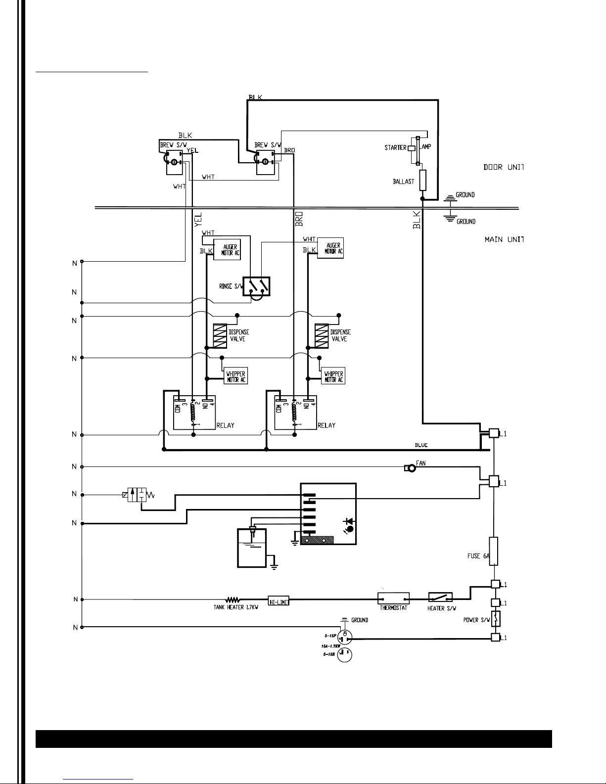
GB3, GB3M
(120V/240, 3kW, 1 PH, L1, L2, +NTL + GND) w/ Relays
BLKBLK
DOOR UNIT
N
N
N
N
BREW SW
WHT
COM
WHT
BREW SW
BRO
BREW SW
GND
YEL
WHT
AUGER
BLK
MOTOR AC
RINSE
SWITCH
DISPENSE
VALVE
WHIPPER
MOTOR AC
3
2
4
NO
COM
BRO
WHT
BLK
3
2
NO
4
AUGER
MOTOR AC
DISPENSE
VALVE
WHIPPER
MOTOR AC
COM
WHT
BLK
3
2
NO
4
AUGER
MOTOR AC
DISPENSE
VALVE
WHIPPER
MOTOR AC
BLK
GND
RELAY
1
RELAY
N
1
RELAY
1
BLUE
L1
N
N
N
N
WATER INLET VALVE
HEATER
LIGHT
WATER
LEVEL
PROBES
WATER
TANK
DUAL LIQUID LEVEL CONTROL
RED
WHT
BLU
YEL
GRN
GND
3KW-HEATER
1 FILL
2 AC-1L
3 AC-2N
4 L-LEVEL
5 H-LEVEL
6 COMMON
THERMOSTAT
HI-LIMIT
RED
LED
BLK
WHT
BLK
L1
FUSE 6A
HEATER SWITCH
L1
POWER SWITCH
N
L2
L1
G
GND
Page 28

28 Cecilware
®
GB Series
Wiring Diagrams (continued)
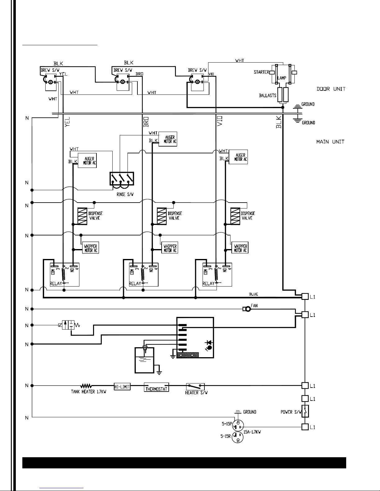
GB3M, 3K
(120V/240, 6kW, 1 PH, L1, L2, +NTL + GND) w/ Relays
Page 29
GB Series Cecilware
®
29
Wiring Diagrams (continued)
GB3M-W
[120V, 1.7KW, 1 PH, 2 WIRES + GROUND] W/ RELAYS
WATER INLET VALVE
WATER
LEVEL
PROBES
WATER
TANK
DUAL LIQUID LEVEL CONTROL
GND
RED
WHT
BLU
YEL
GRN
1 FILL
2 AC-1L
3 AC-2N
4 L-LEVEL
5 H-LEVEL
6 COMMON
BLK
LED
Page 30

30 Cecilware
®
GB Series
Wiring Diagrams (continued)
GB4, GB4M, 4M-8, 4MD
[120V, 1.7KW, 1 PH, 2 WIRES + GROUND] W/ RELAYS
WATER INLET VALVE
WATER
LEVEL
PROBES
WATER
TANK
DUAL LIQUID LEVEL CONTROL
RED
WHT
GRN
GND
BLU
YEL
1 FILL
2 AC-1L
3 AC-2N
4 L-LEVEL
5 H-LEVEL
6 COMMON
BLK
LED
Page 31

GB Series Cecilware
®
31
Wiring Diagrams (continued)
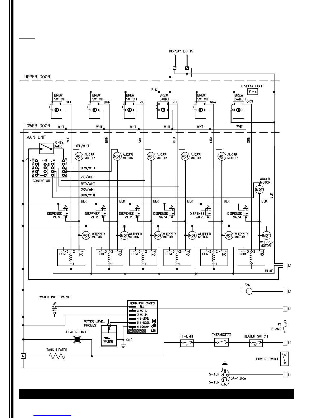
GB5M
[120V, 1.7KW, 1 PH, 2 WIRES + GROUND] W/ RELAYS
Page 32
32 Cecilware
®
GB Series
Wiring Diagrams (continued)
GB6M
120V
Page 33

GB Series Cecilware
®
33
Wiring Diagrams (continued)
GB2SKI-SUPER
[SINGLE PHASE W/TEACH ME TIMERS] 240 V.AC 6 KW
N
HOT CHOCOLATE
HOT-WATER
HOT CHOCOLATE
L1
WHT
DISPENSE
SPEED
CONTROL
1
YEL
WHT
3
COM
RELAY
SWITCH
2
BLU
2
1
241
POT
-
3
4
+
TRANSFORMER
BLK
4
NO
TEACH-ME
TIMER
3
D.C.
AUGER
MOTOR
DISPENSE
VALVE
STOP SW.
241
HOT WATER SW.
HOT
WATER
DISPENSE
VALVE
3
RINSE SWITCH
DISPENSE
SWITCH
SPEED
CONTROL
1
YEL
WHT
COM
RELAY
241
POT
3
TEACH-ME
TIMER
GND
DOOR UNIT
-
3
4
2
+
BLU
TRANSFORMER
BLK
2
NO
4
3
D.C.
AUGER
MOTOR
GND
MAIN UNIT
BLK
1
DISPENSE
VALVE
WATER INLET VALVE
WATER
LEVEL
PROBES
WATER
TANK
DUAL LIQUID LEVEL CONTROL
RED
1 FILL
2 AC-1L
WHT
3 AC-2N
BLU
4 L-LEVEL
YEL
5 H-LEVEL
GRN
6 COMMON
GND
BLK
LED
3 TANK HEATERS - 1 PHASE - 6 KW
HEATER LIGHT
WHT
CONTACTOR
110V COIL
21
3
L2
L3
321
L1
HI-LIMIT
10GA
10GA
THERMOSTAT
HEATER SWITCH
FAN
FUSE
TRANSFORMER
120V
T1
GND
220V
GND
BLK
POWER
SWITCH
L1
L2
G
Page 34
34 Cecilware
®
GB Series
Wiring Diagrams (continued)
GB2SKI-SUPER
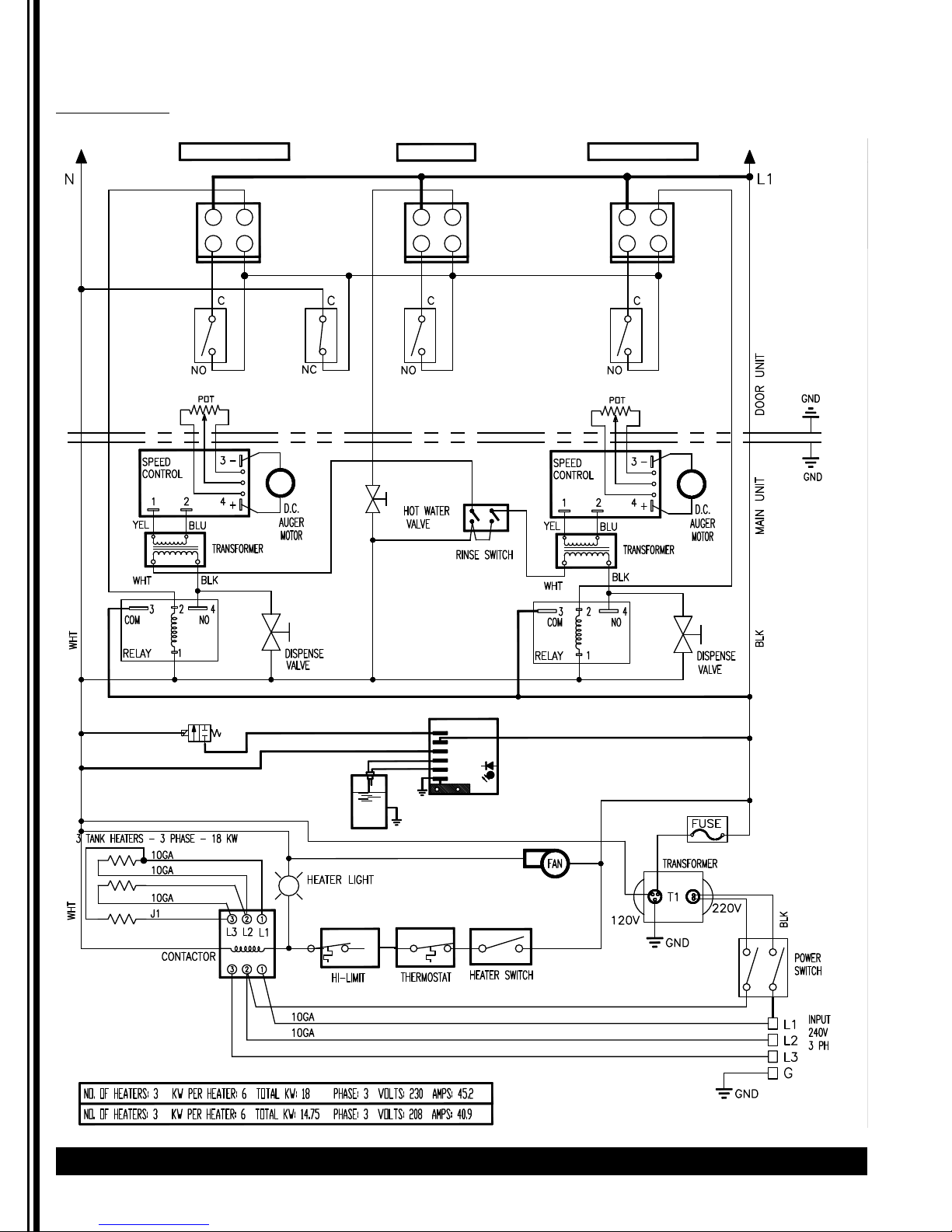
3 PHASE, W/TEACH ME TIMERS 240 V.A.C. 18 KW
HOT CHOCOLATEHOT CHOCOLATE
HOT-WATER
DISPENSE
SWITCH
241
TEACH-ME
TIMER
3
STOP SW.
241
3
HOT WATER SW.
TEACH-ME
TIMER
DISPENSE
SWITCH
241
3
WATER INLET VALVE
WATER
LEVEL
PROBES
WATER
TANK
DUAL LIQUID LEVEL CONTROL
RED
1 FILL
2 AC-1L
WHT
3 AC-2N
BLU
4 L-LEVEL
YEL
5 H-LEVEL
GRN
6 COMMON
GND
BLK
LED
Page 35

GB Series Cecilware
®
35
Page 36

Grindmaster-Cecilware
4003 Collins Lane, Louisville, KY 40245 USA
Phone: 502.425.4776 Toll Free: 800.695.4500
Fax: 502.425.4664
Web: gmcw.com Email: info@gmcw.com
©2016 Grindmaster-Cecilware
Printed in USA
0516 Form # CW-314-01
Part # 390-00013
 Loading...