

Page 1
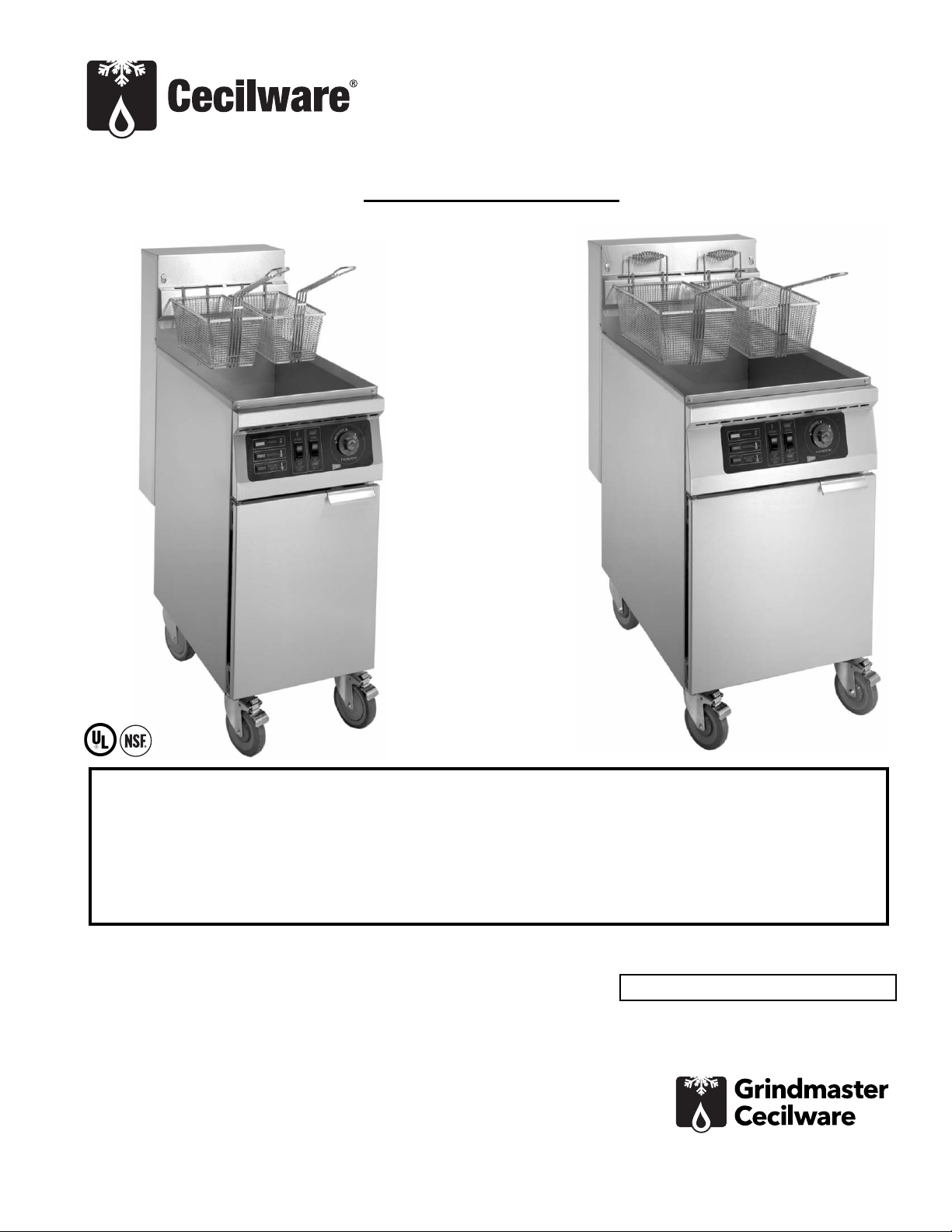
Electric Deep-Fat Fryer
Operator Manual
EFP40, EFS40, EFS65
Grindmaster-Cecilware
4003 Collins Lane, Louisville, KY 40245 USA
Phone: 502.425.4776 Toll Free: 800.695.4500
Fax: 502.425.4664
Web: gmcw.com Email: info@gmcw.com
Safety Information .....................................2
Specifications..............................................3
Unpacking...................................................3
Installation..................................................4
Operation....................................................5
Cleaning......................................................6
Maintenance...............................................6
Troubleshooting .........................................8
Parts Diagram .............................................9
Parts List....................................................10
Wiring Diagram........................................11
Thank you for purchasing this quality fryer. For your safety and the safety of others, read all warnings
and the operator’s manual before installing or using the product. Properly instruct all operators. Keep
training records. For future reference, record serial number here:
Table of Contents
©2016 Grindmaster-Cecilware
Printed in USA
0916 Form # CW-336-01
Part # 390-00083
Grindmaster-Cecilware provides the
industry’s BEST warranty. Visit gmcw.com
for warranty terms and conditions.
Model: EFS-65
Model: EFS-40
Both fryers are shown with optional casters.
Page 2
2 Cecilware
®
Fryer
Safety Information
Important Safety Information
This is the safety alert symbol. It is used to alert you to potential personal injury hazards. Obey all safety messages
that follow this symbol to avoid possible injury or death.
WARNING
• Do not deform power cord.
• Follow national and local electrical codes.
• Do not store or use gasoline or other flammable vapors and liquids in the vicinity of this or any other
appliance.
• Use only on a dedicated circuit load that is properly protected and capable of the rated load. Do not use
extension cords as this could result in electrical shock, overheating, and fire.
• Risk of electrical shock. Disconnect power before servicing or cleaning unit. Contact Grindmaster-Cecilware
Technical Service for service assistance.
• If the supply cord is damaged, it must be replaced by the manufacturer, its service agents, or similarly
qualified persons in order to avoid a hazard.
• Due to the heat a fryer may produce, it must be placed on a non-combustible surface with at least 6 inches
clearance from all combustible and noncombustible surfaces at side and rear.
• Fryer must only be operated when cooking oil or shortening is at recommended oil level.
• Do not move a fryer filled with hot liquid.
• Let hot oil cool sufficiently before draining. Hot oil will crack glass and also melt plastic vessels.
• Wear oil-proof insulated gloves when working at fryer filled with hot oil.
• Do not store combustible materials on top or under any fryer.
FAILURE TO COMPLY TO THE ABOVE RISKS PERSONAL INJURY, SHOCK HAZARD, FIRE, OR DAMAGE TO
EQUIPMENT.
CAUTION
• Read and understand the operating instructions in this manual thoroughly. Only allow properly trained
persons to operate this machine.
• Stay alert at all times during operation.
• Operate with care. Surfaces will get very hot and may cause serious burns.
NOTICE
• Keep operating area clean.
For your safety and the safety of others, read all warnings and the operator’s manual before installing or using
the product.
DANGER: This term warns the user of imminent hazard that will result in serious injury or death.
WARNING: This term refers to a potential hazard or unsafe practice, which could result in serious injury or
death.
CAUTION: This term refers to a potential hazard or unsafe practice, which could result in minor or moderate
injury.
NOTICE: This term refers to information that needs special attention or must be fully understood.
Page 3
Fryer Cecilware
®
3
Unpacking
With the container upright, cut the plastic straps around shipping container and lift off top, exposing the fryer.
Carefully lift unit out of shipping container, and inspect immediately for shipping damage. Accessories are packed
inside the fryer tank. Your fryer was shipped in a carton designed to give it maximum protection. It was thoroughly
inspected before leaving the factory. File any claims for shipping damage or irregularities directly with the carrier.
ACCESSORIES WITH UNIT
1 Basket Hanger
2 Baskets
1 Drainpipe Extension
OPTIONAL ACCESSORIES
1 Cover
1 Twin Basket
4 Swivel Casters
1 Restrainer
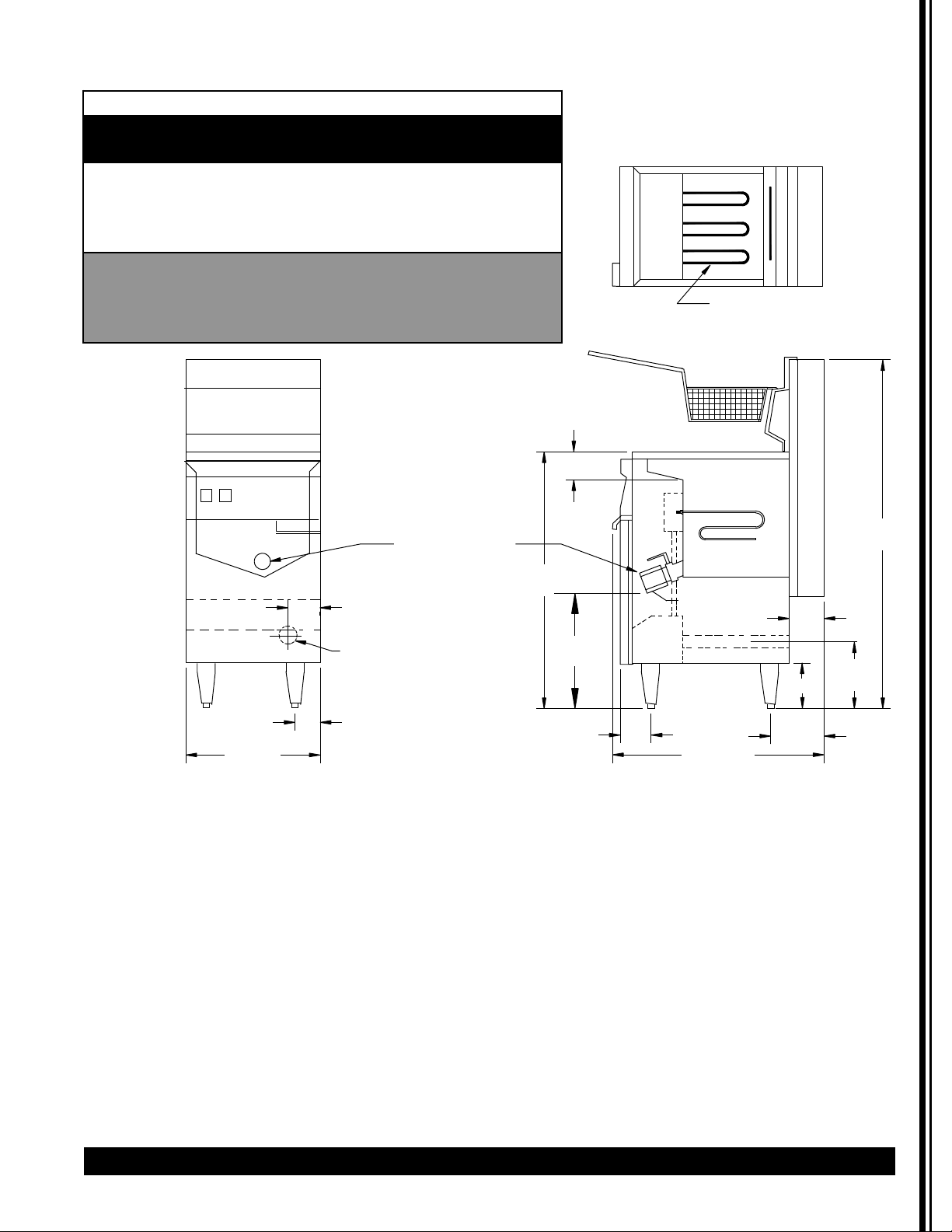
Specifications
Electrical Specificaons
Model kW V SINGLE PHASE THREE PHASE
AMPS AWG AMPS AWG
EF‐40 18.0 208 86.5 4 50.0 6
18.0 240 75.0 4 43.3 6
18.0 220/380 ‐ ‐ 47.3/27.4 6
18.0 240/415 ‐ ‐ 43.3/25.1 6
EF‐65 21.0 208 101.0 4 58.4 6
21.0 240 87.5 4 50.6 6
21.0 220/380 ‐ ‐ 55.2/31.9 6
21.0 240/415 ‐ ‐ 50.6/29.6 6
ELEMENTS
4 1/2
45
9 1/2
WIDTH
DRAIN VALVE
2 1/2
1 3/16
KNOCKOUT
1 3/4
WORKING
HEIGHT
35
18
3 1/4
3
6
4 3/4
DEPTH
INCLUDING HANDLE
Page 4
4 Cecilware
®
Fryer
Installation
Location and Restraint of Fryer
The fryer must be placed in operating position in such
a way that accidental tipping of unit, or spilling of hot
oil, cannot occur.
The unit may be restrained by either:
• Connecting unit in battery with others, or
• Locating unit in an alcove, or
• Additional mechanical means of restraint.
Air Supply and Ventilation -
The area around the appliance must be kept clear to
avoid obstruction to the flow of ventilation air as well
as for ease of maintenance and service.
UNDER NO CIRCUMSTANCE SHOULD THE INTERIOR OF
THE FRYER'S CABINET BE USED FOR STORAGE.
Means must be provided for any commercial, heavyduty cooking appliance to exhaust cooking vapors to
the outside of the building.
Filters and drip troughs should be part of any industrial
hood. Consult local codes before constructing and
installing any hood.
Clearances
Minimum clearance from combustible and
noncombustible construction is 6” from the sides and
6” from the back. This unit can be placed on either a
combustible or non-combustible surface. At least 16”
clearance must be provided between the frying surface
of the fryer and the surface flames of any adjacent
cooking unit.
Mechanical Installation
MOUNTING LEGS OR CASTERS - Carefully tip fryer up on
its back and screw legs or (optional) casters into the
threaded base of fryer. When installing casters make
sure the swivel lock casters are mounted towards the
front of the fryer. A high strength Restrainer must be
installed when casters are used. Avoid putting any
strain on rear legs or casters when tipping fryer back to
an upright position.
POSITIONING - DO NOT PUSH against any of the edges
of the unit in an attempt to adjust its position. Lift unit
slightly to maneuver into desirable installation position.
Pushing the unit will increase the probability of
bending the legs or internal connectors.
LEVELING - Once the fryer is installed, the unit should
be leveled, side-to-side and front-to-back, using a
carpenter's spirit level. On smooth and level floors, level
the unit with the screw threads of the legs. If the floor
is uneven or has a slope, shims may be required.
Electrical Installation
RATING PLATE - The rating plate is located on the inside
of the fryer door. Information on the rating plate
pertains to the power output (KW) of the heaters and
other electrical requirements.
The information presented in this manual is for
reference only. Installations must comply with local
codes.
• Connections to the terminal block and grounding lug
should be made through the hole provided for this
purpose in the electric control box.
NOTICE Unit must only be installed and operated
with legs or casters provided by manufacturer.
WARNING: Electrical shock hazard. This is high
voltage equipment. Make sure main disconnect is off
before connecting fryer.
WARNING: ELECTRIC SHOCK HAZARD!
Installation of this appliance must be performed by
qualified service personnel only. Improper installation
could result in electrocution.
NOTICE: This equipment must be installed in
compliance with applicable Federal, State, and/or Local
electrical codes having jurisdiction or, in the absence of
local codes, with the National Electric Code, NFPA 70
(latest revision).
3
7
5
3
2
5
5
2
R
2
7
5
2
Page 5
Fryer Cecilware
®
5
Installation (continued)
• The wiring diagram for each unit is attached to the
inside of the fryer door. Wiring diagrams for all units
are included in this manual. Amperage for each unit
depends on the type of installation and accessories
supplied with the unit.
Initial cleaning
Before using the unit, the tank should be washed
thoroughly with hot, soapy water to remove oil residues
and dust, then rinsed and wiped dry. Accessories,
shipped with the unit, should also be washed.
Verification
1. Remove the crumb screen.
2. Fill the tank with hot or cold water to the "oil
level" line.
3. Set the operating thermostat dial to 225
degrees, just above the boiling point of water,
and engage cook cycle. (Cook switch ON)
4. Turn ON the power switch on the control panel.
These steps check the heating element
operation, initial thermostat calibration, and
clean the tank for initial production.
5. When the water starts to boil, turn the dial to
just below 212 degrees. The elements will turn
off and the water will stop boiling.
6. When satisfied that heaters and thermostat are
operating properly, drain the tank and dry
thoroughly.
7. Close the drain valve.
Final Preparation
• COOKING OIL: fill tank to the "oil level" line marked
on the tank.
• SOLID SHORTENING
: either melt shortening first or cut
it into small pieces and pack carefully around the
heating element. Leave no air space around the
elements and be careful not to disturb the sensing
bulbs. Melt the shortening either with the MELT or
MELT/COOK cycle or by using the COOK cycle and
turning the heaters ON for FIVE (5) to TEN (10) SECONDs
then OFF for ONE (1) MINUTE using the temperature
control dial. Repeat this cycle until the shortening has
melted. If smoke develops during this melting process
shorten the "on" cycle and lengthen the "off" cycle.
• When the shortening has melted and the tank has
filled to the "oil level", replace the crumb screen.
• Before starting operation, set the unit into COOK cycle
mode and turn the thermostat to the operating
temperature. Allow the oil or shortening temperature
to stabilize, and then check with a high quality
immersion thermometer.
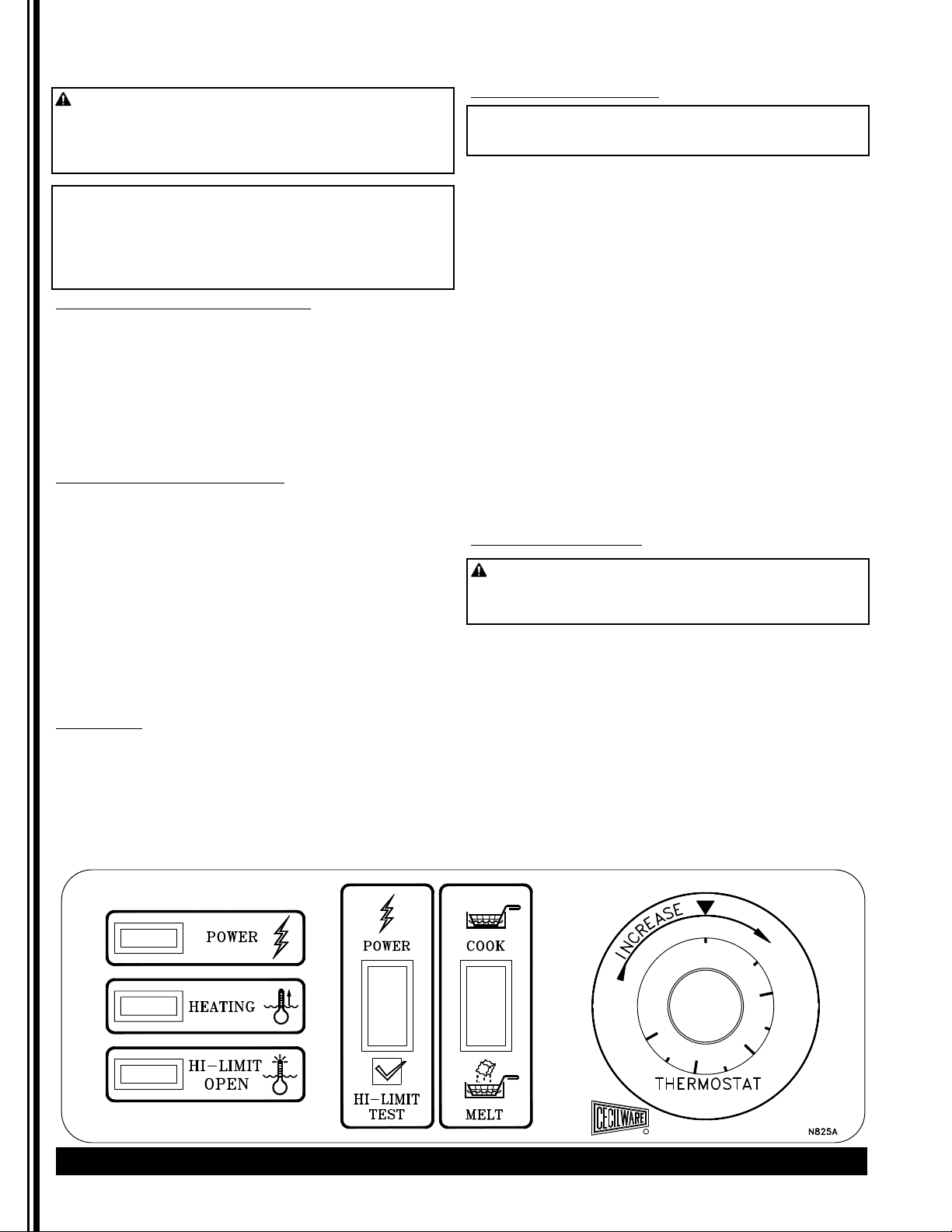
Operation
Daily Operation
AT START OF WORKDAY - Check fryer visually for
• Power switch "OFF".
•
Temperature control dial "OFF". (Counterclockwise)
GENERAL TURN-ON PROCEDURE:
• If fryer is empty, fill the tank with oil to the "oil
level" mark.
• If using solid shortening, cut and pack as
previously described.
• Turn Power switch "ON".
• To melt solid shortening, turn the Melt
(Melt/Cook) switch "ON" and set the
temperature control dial to 200 degrees.
• Put unit into cook cycle (Cook switch "ON") and
set the temperature to 350 degrees
(recommended). The frying compound will
stabilize in less than 30 minutes and the unit
will be ready for production.
USE OF FRYER - for best results:
• For consistent product quality, and long-term
savings, use high quality liquid frying oil.
• If using solid shortening, never attempt to melt
a block of shortening by setting it whole on top
of the heating elements. This is dangerous as it
may burn-out the elements and start a fire.
• The recommended temperature of 350 degrees
should be the usual temperature for most
cooking operations. However, frying should be
carried out at the lowest temperature which
will produce a high quality product while
ensuring maximum life of the frying compound.
• When the fryer is not in use, temperature
control should be set at a lower temperature
than that used during cooking. Light loads may
also be cooked at lower temperatures.
• Salting: Do not salt food over the fryer tank.
Salt deteriorates the frying compound quickly.
WARNING To prevent serious burn injury:
Fryer must only be operated when cooking oil or
shortening is at recommended oil level.
Do not move a fryer filled with hot liquid.
Let hot oil cool sufficiently before draining. Hot oil will
crack glass and also melt plastic vessels.
Wear oil-proof insulated gloves when working at fryer
filled with hot oil.
WARNING: Do not engage cook cycle until
shortening has fully melted.
Page 6

6 Cecilware
®
Fryer
Operation (continued)
FILTERING -The frying compound should be filtered at
least once a day, or more frequently when doing high
volume cooking. This assures the longest possible life
for the frying compound, minimizes the transfer of
flavors from batch to batch, and gives better taste to
the food being prepared.
AT CLOSING TIME -Turn the power switch on the fryer
panel OFF and set the temperature control dial OFF
Drain and filter the frying compound. Allow compound
to cool down sufficiently to prevent burns to the
operator. Cover the fryer tank.
SHUT DOWN - When shutting down for longer than
just overnight, drain the frying compound, clean the
tank thoroughly, either discard the compound or return
it filtered to the tank and then cover it.
Cleaning
DAILY
• Take off and wash fryer basket(s), crumb screen
and basket hanger.
• Clean all exterior surfaces of the unit. Do not
use cleansers, steel wool, or any other abrasive
cleaning material on steel.
• Filter the frying compound or replace as
necessary. More frequent filtering may be
required if the unit is heavily used.
WEEKLY
• Drain the tank completely, either into a filter or
a steel container. Do not use plastic buckets or
glass containers.
• Clean the vessel with a nonabrasive commercial
cleaner or hot water and a strong detergent.
Drain the cleaning solution.
• Close drain valve and fill tank with fresh
cleaning solution. Bring the cleaning solution to
a boil, turn down the heat, and let the solution
stand until deposits or spots can be rubbed off
with a Teflon brush.
• Scrub tank walls, bottom and heating elements
(Be careful not to disturb the sensing bulbs),
then drain tank and rinse with clean water.
• Refill tank with clean water and bring to a full
boil. Drain, rinse, and dry tank thoroughly.
• Refill with frying oil or compound (see Daily
Operation in Operation section).
GENERAL CLEANING SUGGESTIONS
DO NOT USE steel wool or abrasive cloths, cleaners or
powders. If it is necessary to scrape steel to remove
encrusted materials, soak the area with hot cloths to
loosen the material, and then use a wood or nylon
scraper.
DO NOT USE a metal knife, spatula, or any other metal
tool to scrape steel.
Keep all exterior surfaces of the griddle free of splashed
grease and other dirt by washing regularly with hot
water and soap. Rinse and wipe dry: then polish with a
soft cloth.
Maintenance
High Limit Control Test:
To test whether high limit control is working properly,
fill the fry tank with oil up to maximum oil level. Then
place a suitable thermometer in the fry tank with bulb
deeply immersed in oil. Set thermostat to maximum
position. When temperature has reached cut out level
(Heating indicator light goes OFF), depress the High
Limit Test Switch which bypasses thermostat and allows
fat to heat up until high limit control is activated. When
Red High Limit Pilot goes ON, note the temperature on
thermometer (should be between 440 deg. and 475
deg.). Allow fryer to cool; then press red reset button(s)
on the left section of control box, located behind the
access door. If high limit control does not shut off fryer
before 475 degrees is reached, have it replaced.
CAUTION: Allow oil to cool sufficiently before
draining it.
NOTICE: The following procedures must be
performed by qualified service personnel only. Factory
approval must be obtained prior to doing any warranty
work.
Page 7

Fryer Cecilware
®
7
Maintenance (continued)
Page 8

8 Cecilware
®
Fryer
Troubleshooting
If the elements will not heat:
1. Check if all wires to the solid state temperature
control or melt cycle timer are secure.
2. With the power on/off switch "ON", manually
reset the high limit thermostat (push the red
button(s) behind the access door).
3. Check that correct line voltage exists across
terminal block terminals L1-L2, L2-L3 and L3-L1
(three phase connection) or L1-L2 (single phase
connection).
4. Check if the main or branch circuit breakers or
fuses are tripped or blown.
5. If the panel power indicator light is ON but
latching contactor is not actuated, check
continuity from the latching contactor coil to
the power indicator light.
If the panel power indicator light does not light:
1. Check line voltage across the power indicator
light, and then if voltage does not exist
proceed as follows:
2. Check the fuse for line voltage between the
load side and L3.
3. Check the power on-off switch for line voltage
between the load side and L3.
4. Check the high limit thermostat for line voltage
between the load side and L3; if resetting does
not produce results, replace the high limit
thermostat.
5. Check the operating thermostat for line
voltage between the load side and L3; if
defective, replace thermostat.
Excessive warm-up time; slow or inadequate
temperature recovery; uneven heating:
1. Check temperature controller adjustment.
2. Place the sensing bulb of a high quality
immersion thermometer about 1.5" above the
thermostat sensing bulb or thermistor probe
and set the controller dial to 350 degrees.
3. Wait at least 20 minutes for the oil
temperature to stabilize.
4. If the temperature is not within +/- 10 degrees
of the dial setting, see “Probe Test” below for
the solid state temperature controller or
“Temperature Adjustment” for the thermostat
temperature controller.
5. Check heating circuit
6. With the power switch "ON" turn the
temperature control dial until the power and
heating indicator lights are both on. The
latching and cycling contactors should both be
actuated.
7. Check the load side of the contactors to the
heating element terminals. Each element
should draw as shown:
Excessive temperature overshoot during warmup; overheating; scorching; high limit switch
requires frequent re-setting:
1. Check temperature controller (see Temperature
Adjustment below).
2. Check thermistor probe.
3. Check that the thermostat bulb or thermistor
probe in the tank has not been moved out of
operating position.
TEMPERATURE ADJUSTMENT (For units with
mechanical thermostat controls)
1. Mount the bulb of a high quality immersion
thermometer at the same level as the
thermostat bulb. To adjust temperature, turn
the thermostat knob to its maximum position
(in clockwise direction).
2. Pull off the dial knob and insert a small
screwdriver into the adjustment screw in the
center of the shaft. If the liquid compound is
hotter than the setting turn the screw
CLOCKWISE TO LOWER THE TEMPERATURE.
3. If the liquid compound is cooler than the
setting turn the screw COUNTERCLOCKWISE
TO RAISE THE TEMPERATURE.
MAKE ALL TEMPERATURE ADJUSTMENTS, UP OR
DOWN, IN INCREMENTS OF 1/4 TURN. IF THIS
CALIBRATION FAILS, REPLACE THERMOSTAT.
If you need help, call Grindmaster-Cecilware Technical
Service Department, (502) 425-4776 or (800) 695-4500
(USA & Canada only) (Monday through Friday 8 AM - 6
PM EST). Please have the model and serial number
ready so that accurate information can be given. The
rating plate is located on the inside of the fryer door.
Information on the plate includes the model and serial
number of the unit.
Prior authorization must be obtained from
Grindmaster- Cecilware for all warranty claims.
Grindmaster-Cecilware provides the industry’s
BEST warranty. Visit our website at GMCW.com
for warranty terms and conditions.
Model at 208V at 240V
EF-40 29 AMPS 25 AMPS
EF-65 34 AMPS 29 AMPS
Page 9

Fryer Cecilware
®
9
Parts Diagram
7
6
25
31
3
16
36
26
27
28
8
29
30
23
32
17
18
19
15
14
13
22
22
Page 10

10 Cecilware
®
Fryer
Parts List
ITEM # DESCRIPTION EFS/EFP-40 EFS/EFP-65
1 Basket Support Bracket T536A T644AL
2 Basket Support Fastener P281 A P281 A
3 Fry Tank (Stainless Steel) T787Q T820Q
3 Fry Tank (Mild Steel) T826Q T829Q
4 Fry Basket, Small V174P V180P
5 Crumb Screen V172A V179A
6 Fascia Assembly U919Q U958Q
7 Thermostat Control L345E L345E
8 Thermostat Knob M099A M099A
9 Drain Valve D048A D048A
10 Drain Pipe J062A J062A
11 Magnetic Catch U008A U008A
12 Door Hinge U579A U579A
13 Adjustable Leg (1 Leg) M219B M219B
14 Swivel Caster with Locking Device (Optional) M015A M015A
15 Swivel Caster (Optional) M014A M014A
16 Heating Element 208V G250Q G249Q
16 Heating Element 240V G246Q G245Q
17 Junction Box U881A U882A
18 Cover (Junction Box) U884A U885A
19 Electric Control Box U962Q U949Q
20 Ground Lug B081A B081A
21 Terminal Block B083A B083A
22 Fuse C395AL C395AL
23 Fuse Holder C396AL C396AL
24 Hi-Limit Control L346A L346A
25 Clear Pilot L420A L420A
26 Red Pilot L422A L422A
27 Power Switch L408A L408A
28 Cook Switch (Mechanical) L407A L407A
29 Contactor C036AL C036A
30 Auxiliary Circuit Terminal Block B084A B084A
31 Green Pilot L421A L421A
33 Solid State Timer L744A L744A
34 Fuse Block 208V 1 Phase C137A C137A
34 Fuse Block 208V 3 Phase C137A C137A
34 Fuse Block 240V 1 Phase CA61A C137A
34 Fuse Block 240V 3 Phase CA61A C137A
35 Fuse 208V CA64A CA36AL
35 Fuse 208V CA64A CA36A
36 O-Ring (heating elements) K790A K790A
Page 11

Fryer Cecilware
®
11
Wiring Diagram
Page 12

12 Cecilware
®
Fryer
Wiring Diagram (continued)
Page 13

Fryer Cecilware
®
13
Wiring Diagram (continued)
Page 14

14 Cecilware
®
Fryer
Wiring Diagram (continued)
Page 15

Fryer Cecilware
®
15
Page 16

Grindmaster-Cecilware
4003 Collins Lane, Louisville, KY 40245 USA
Phone: 502.425.4776 Toll Free: 800.695.4500
Fax: 502.425.4664
Web: gmcw.com Email: info@gmcw.com
Grindmaster-Cecilware provides the
industry’s BEST warranty. Visit gmcw.com
for warranty terms and conditions.
©2016 Grindmaster-Cecilware
Printed in USA
0916 Form # CW-336-01
Part # 390-00083
 Loading...