

Page 1
HEAVY DUTY COMMERCIAL
N828A 3/00
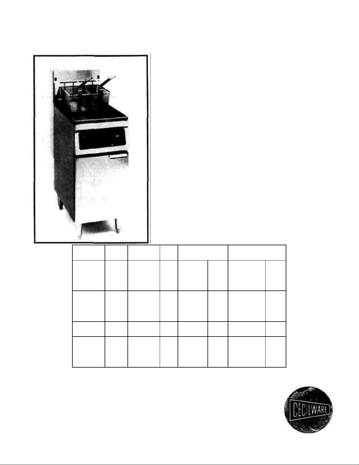
ELECTRIC DEEP-FAT FRYERS
CONTENTS
• SPECIFICATIONS
• INSTALLATION
• OPERATION
• MAINTENANCE
• TROUBLESHOOTING
• SPARE PARTS LISTING
• WIRING DIAGRAMS
MODEL KW VOLT HZ AMPS AWG AMPS AWG
EFS/EFP 13.5 208 60 64.9 6 37.5 8
-30 13.5 240 60 56.3 6 32.5 8
EFS/EFP 18.0 208 60 86.5 4 60.0 6
-40 18.0 240 60 75.0 4 43.3 6
EFS/EFP 21.0 208 60 101.0 4 58.4 6
-65 21.0 240 60 87.5 4 50.6 6
CECILWAKE CORPORATION
43-05 20th Avenue
Long Island City, N.Y. 11105
(718) 932-1414
Fax (718) 932-7860
SINGLE PH. THREE PH.
13.5 220/380 50 — — 35.5/20.5 8
13.5 240/415 50 — — 32.5/18.5 8
18.0 220/380 50 — — 47.3/27.4 6
18.0 240/415 50 — — 43.3/25.1 6
21.0 208 60 — — 58.2 6
21.0 240 60 — — 50.5 6
21.0 220/380 50 — — 55.2/31.9 6
21.0 240/415 50 — — 50.6/29.6 6
Page 2

••••• IMPORTANT •••••
SAFE OPERATION OF YOUR EQUIPMENT DEPENDS ON ITS PROPER INSTALLATION.
INSTALLATION MUST CONFORM TO LOCAL CODES OR, IN THE ABSENCE OF LOCAL
CODES, WITH THE NATIONAL ELECTRIC CODE, NFPA 70 (LATEST REVISION).
LOCAL BUILDING CODES USUALLY WILL NOT PERMIT A DEEP FAT FRYER WITH ITS
OPEN TANK OF HOT OIL TO BE INSTALLED NEAR AN OPEN FLAME OF ANY TYPE
(BROILER, OPEN BURNER, ETC.). CHECK LOCAL CODES BEFORE INSTALLING.
ALL CECILWARE HEAVY DUTY COMMERCIAL DEEP FAT FRYERS MUST ONLY BE
CONNECTED TO THE TYPE OF ELECTRICAL SERVICE INDICATED ON THE RATING PLATE
FOR THE PARTICULAR UNIT IN QUESTION.
FRYER MUST ONLY BE OPERATED WHEN THE COOKING OIL OR SHORTENING IS AT
RECOMMENDED OIL LEVEL.
DO NOT MOVE A FRYER FILLED WITH HOT LIQUID.
LET HOT OIL COOL SUFFICIENTLY BEFORE DRAINING. HOT OIL WILL CRACK GLASS
AND ALSO MELT PLASTIC VESSELS.
WEAR OIL-PROOF INSULATED GLOVES WHEN WORKING AT FRYER FILLED WITH HOT
OIL.
DO NOT LET WATER SPLASH INTO A TANK OF HOT OIL. IT WILL SPLATTER AND CAN
CAUSE SEVERE BURNS.
2
Page 3
DESCRIPTION AND SPECIFICATIONS
Heavy Duty Electric Deep Fat Fryers by Cecilware Corporation are energy-efficient electrical cooking units.
All units are shipped completely assembled, with accessories packed inside the fryer tank. All units are adjusted,
tested and inspected at the factory prior to crating and shipment.
TANK - Choice of 16 gauge Stainless Steel or 14 gauge Mild Steel tank, heliarc welded for leakproof
operation.
BODY - Heavy duty 18 gauge Stainless Steel, or Enameled Steel with unibody construction for long life.
DRAINAGE -1 /4" ball valve slanted for fast draining of fat.
ELECTRICAL CONTROLS - All controls are mounted on the front control panel for easy operation.
MELT CYCLE (ALL UNITS) -This feature pulses the heating elements ON and OFF at a controlled rate.
This cycle should be employed when the unit is used with SOLID SHORTENING.
AUTOMATIC SAFETY FEATURE - High temperature detection shuts off power to the heating elements, if
the controlling thermostat fails.
RATING PLATE - The rating plate is located on the inside of the fryer door. Information on the plate
includes the model and serial number of the unit. When communicating with the manufacturer about a unit, or
requesting parts or information, this data is essential for proper identification. Other information on the rating
plate pertains to the power output (KW) of the heaters and other electrical requirements.
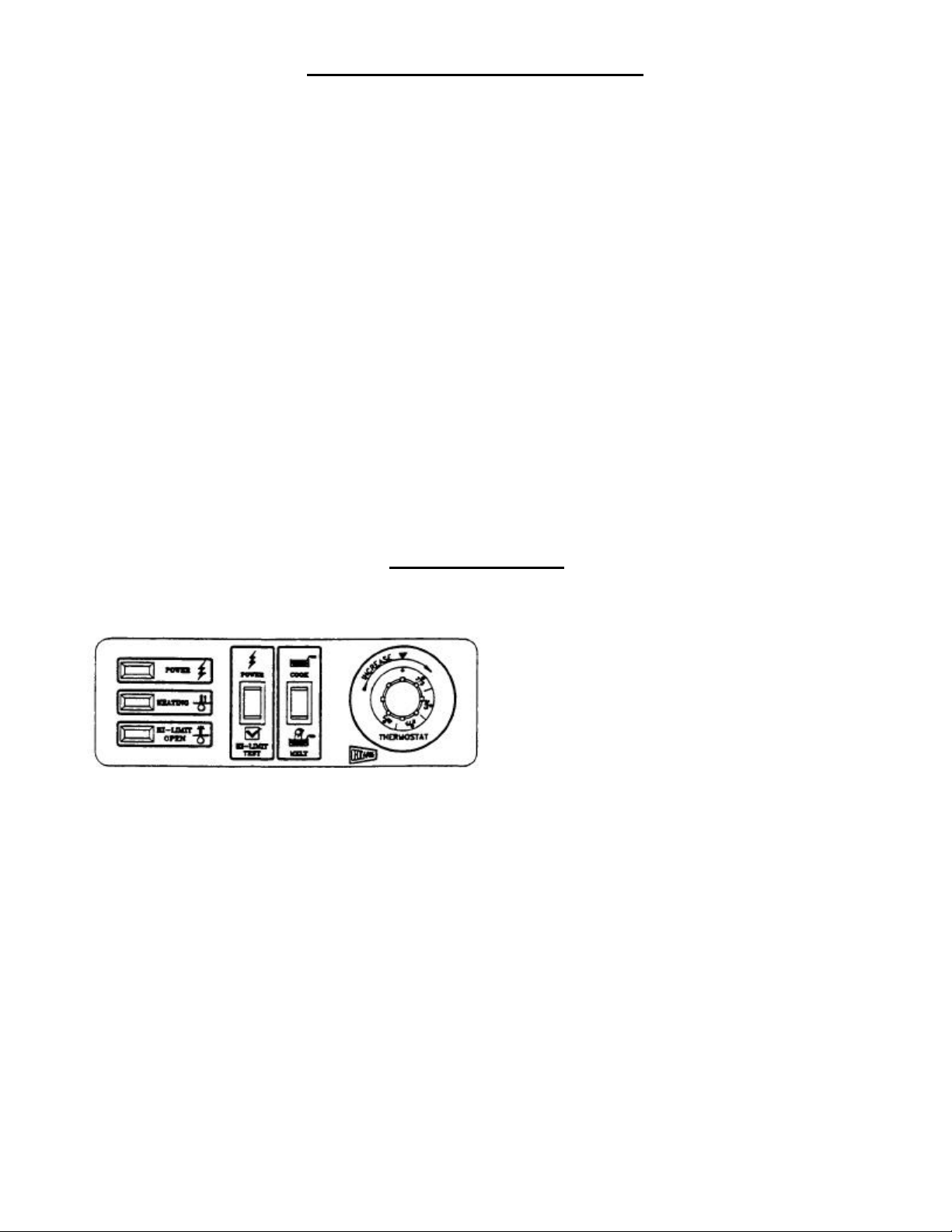
MECHANICAL (M) FIG. 1.1
FRYER CONTROLS
MODEL # SPECIFICATIONS
EFP-40BM Mechanical temperature control
EFP-40BSSM and melt cycle timer.
EFP-40M
EFS-40M
EFP-30M
EFS-30M
EFP-65M
EFS-65M
3
Page 4

PRE-INSTALLATION
IMPORTANT: Installation of heavy-duty electrical appliances should be made by a licensed electrician. Installations) must comply with applicable state and local codes, or the following national standards:
• National Electrical Code ANSI/NFPA 70 - latest revision
American National Standards Institute
1430 Broadway New York, N.Y. 10018
• NFPA Standards #96 and #211
National Fire Protection Association
470 Atlantic Avenue
Boston, MA 02110
CAUTION
Local building codes usually will not permit a deep fat fryer with
its open tank of hot oil to be installed near an open flame of any
type (broiler, open burner, etc.). Check local codes before
installing.
AIR SUPPLY AND VENTILATION - The area around the appliance must be kept clear to avoid obstruction to
the flow of ventilation air as well as for ease of maintenance and service.
• UNDER NO CIRCUMSTANCE SHOULD THE INTERIOR OF THE FRYER'S CABINET BE USED FOR STORAGE.
• Means must be provided for any commercial, heavy-duty cooking appliance to exhaust cooking vapors to
the outside of the building.
• Filters and drip troughs should be part of any industrial hood. Consult local codes before constructing and
installing any hood.
INSTALLING THE FRYER
UNPACKING - With the container upright, cut the plastic straps around shipping container and lift off top,
exposing the Fryer. Check Fryer for any visible damage due to exceptionally rough handling during shipping.
Report damage to the delivering Freight Carrier within 15 days of delivery.
ACCESSORIES WITH UNIT ACCESSORIES (OPTIONAL)
1 Basket Hanger 1 Cover
2 Baskets 1 Twin Basket
1 Drainpipe Extension 4 Swivel Casters
1 Restrainer
MOUNTING LEGS OR CASTERS - Carefully tip Fryer up on its back and screw legs or (optional) casters into
the threaded base of Fryer. When installing casters make sure the swivel lock casters are mounted towards the
front of the Fryer. A high strength Restrainer must be installed when casters are used. Avoid putting any strain
on rear legs or casters when tipping Fryer back to an upright position.
POSITIONING - DO NOT PUSH against any of the edges of the unit in an attempt to adjust its position. Lift unit
slightly to maneuver into desirable installation position. Pushing the unit will increase the probability of bending
the legs or internal connector's.
LEVELING - Once the Fryer is installed, the unit should be leveled, side-to-side and front-to-back, using ?
carpenter's spirit level. On smooth and level floors, level the unit with the screw threads of the legs. If the floor is
uneven or has a slope, shims may be required.
4
Page 5

ELECTRICAL CONNECTIONS
The information presented in this manual is for reference only. Installations must comply with local codes.
• Connections to the terminal block and grounding lug should be made through the hole provided for this
purpose in the electric control box.
• The wiring diagram for each unit is attached to the inside of the Fryer door. Wiring diagrams for all units
are included in this manual. Amperage for each unit depends on the type of installation and accessories
supplied with the unit.
INITIAL START-UP
CLEANING:
New units are wiped clean with solvents at the factory to remove dirt, grease, etc., then given a light coat of
oil. Before using the unit, the tank should be washed thoroughly with hot, soapy water to remove oil residues
and dust, then rinsed and wiped dry. Accessories, shipped with the unit, should also be washed.
WARNING: CLOSE THE DRAIN VALVE COMPLETELY BEFORE FILLING THE VESSEL.
PREHEATING THE FRYER TANK:
• Remove the crumb screen.
• Fill the tank with hot or cold water to the "oil level" line.
• Set the operating thermostat dial to 225 degrees, just above the boiling point of water, and engage cook
cycle. (Cook switch ON) [Fig. 1.1 & 1.2]
• Turn ON the power switch on the control panel. These steps check the heating element operation, initial
thermostat calibration, and clean the tank for initial production.
• When the water starts to boil, turn the dial to just below 212 degrees. The elements will turn off and the
water will stop boiling.
• When satisfied that heaters and thermostat are operating properly, drain the tank and dry thoroughly.
• Close the drain valve.
FINAL PREPARATION
• Cooking oil: fill tank to the "oil level" line marked on the tank.
• Solid shortening: either melt shortening first or cut it into small pieces and pack carefully around the
heating element. Leave no air space around the elements and be careful not to disturb the sensing bulbs.
Melt the shortening either with the MELT or MELT/COOK cycle or by using the COOK cycle and turning
the heaters ON for FIVE (5) to TEN (10) SECONDS then OFF for ONE (1) MINUTE using the temperature
control dial. Repeat this cycle until the shortening has melted. If smoke develops during this melting
process shorten the "on" cycle and lengthen the "off" cycle.
• When the shortening has melted and the tank has filled to the "oil level", replace the crumb screen.
• Before starting operation, set the unit into COOK cycle mode and turn the thermostat to the operating
temperature. Allow the oil or shortening temperature to stabilize, then check with a high quality immersion thermometer.
WARNING
FRYER MUST ONLY BE OPERATED WHEN COOKING OIL OR SHORTENING IS AT RECOMMENDED OIL LEVEL
DO NOT MOVE A FRYER FILLED WITH HOT LIQUID.
LET HOT OIL COOL SUFFICIENTLY BEFORE DRAINING. HOT OI L WILL CRACK GLASS AND
ALSO MELT PLASTIC VESSELS.
WEAR OIL-PROOF INSULATED GLOVES WHEN WORKING AT FRYER FILLED WITH HOT OIL
5
Page 6

DAILY OPERATION
AT START OF WORKDAY - Check Fryer visually for
• Power switch "OFF".
• Temperature control dial "OFF". (Counterclockwise)
GENERAL TURN-ON PROCEDURE:
• I f fryer is empty, fill the tank with oil to the "oil level" mark.
• If using solid shortening, cut and pack as previously described.
• Turn Power switch "ON". [Fig. 1.1 & 1.2]
• To melt solid shortening, turn the Melt (Melt/Cook) switch "ON" and set the temperature control dial to
200 degrees. [Fig. 1.1 &1.2]
WARNING: Do not engage cook cycle until shortening has fully melted.
• Put unit into cook cycle (Cook switch "ON") and set the temperature to 350 degrees (recommended). The
frying compound will stabilize in less than 30 minutes and the unit will be ready for production.
[Fig 1.1 &1.2]
USE OF FRYER - for best results:
• For consistent product quality, and long-term savings, use a high quality liquid frying oil.
• If using solid shortening, never attempt to melt a block of shortening by setting it whole on top of the
heating elements. This is dangerous as it may burn-out the elements and start a fire.
• The recommended temperature of 350 degrees should be the usual temperature for most cooking
operations. However, frying should be carried out at the lowest temperature which will produce a high
quality product while ensuring maximum life of the frying compound.
• When the fryer is not in use, temperature control should be set at a lower temperature than that used
during cooking. Light loads may also be cooked at lower temperatures.
• Salting: Operators sometimes salt food over the Fryer tank. This practice should be avoided, as salt
deteriorates the frying compound quickly and flavors everything else being cooked, not just the batch
being salted.
FILTERING - The frying compound should be filtered at least once a day, or more frequently when doing high
volume cooking. This assures the longest possible life for the frying compound, minimizes the transfer of flavors
from batch to batch and gives better taste to the food being prepared.
AT CLOSING TIME - Turn the power switch on the fryer panel OFF and set the temperature control dial OFF.
Drain and filter the frying compound. Allow compound to cool down sufficiently to prevent burns to the operator.
Cover the fryer tank.
SHUT-DOWN - When shutting down for longer than just overnight, drain the frying compound, clean the tank
thoroughly, either discard the compound or return it filtered to the tank and then cover it.
6
Page 7

CLEANING AND MAINTENANCE
DAILY
• Take off and wash fryer basket(s), crumb screen and basket hanger.
• Clean all exterior surfaces of the unit. Do not use cleansers, steel wool, or any other abrasive cleaning
material on steel.
• Filter the frying compound or replace as necessary. More frequent filtering may be required if the unit is
heavily used.
WEEKLY
• Drain the tank completely, either into a filter or a steel container. Do not use plastic buckets or glass
containers. CAUTION: ALLOW OIL TO COOL SUFFICIENTLY BEFORE DRAINING IT.
• Clean the vessel with a nonabrasive commercial cleaner or hot water and a strong detergent. Drain the
cleaning solution.
• Close drain valve and fill tank with fresh cleaning solution.
• Bring the cleaning solution to a boil, turn down the heat and let the solution stand until deposits or spots
can be rubbed off with a Teflon brush.
• Scrub tank walls, bottom and heating elements (Be careful not to disturb the sensing bulbs), then drain
tank and rinse with clean wa ter.
• Refill tank with clean water and bring to a full boil.
• Drain, rinse, and dry tank thoroughly.
• Refill with frying oil or compound (see Start-Up).
GENERAL CLEANING SUGGESTIONS
DO NOT USE steel wool or abrasive cloths, cleaners or powders. If it is necessary to scrape steel to remove
encrusted materials, soak the area with hot cloths to loosen the material, then use a wood or nylon scraper. DO
NOT USE a metal knife, spatula or any other metal tool to scrape steel.
THE FOLLOWING PROCEDURES MUST BE PERFORMED BY A CECILWARE CORPORATION REPRESENTATIVE.
FACTORY APPROVAL MUST BE OBTAINED PRIOR TO DOING ANY WARRANTY WORK OR CECILWARE CANNOT
BE HELD RESPONSIBLE.
ADJUSTMENTS
High Limit Control Test: To test whether high limit control is working properly, fill the fry tank with oil up to maximum oil level. Then place a suitable thermometer in the fry tank with bulb deeply immersed in oil. Set thermostat to maximum position. When temperature has reached cut out level (Heating indicator light goes OFF),
depress, the High Limit Test Switch [Fig. 1.1 & 1.2] which bypasses thermostat and allows fat to heat up until
high limit control is activated. When Red High Limit Pilot goes ON, note the temperature on thermometer (should
be between 440 deg. and 475 deg.). Allow fryer to cool; then press red reset button(s) on the left sec tion of
control box, located behind the access door. If high limit control does not shut off fryer before 475 degrees is
reached, have it replaced.
7
Page 8

TROUBLESHOOTING
If the elements will not heat up:
• Check if all wires to the solid state temperature control or melt cycle timer are secure.
• With the power on/off switch "ON", manually reset the high limit thermostat (push the red button(s) behind
the access door).
• Check that correct line voltage exists across terminal block terminals L1-L2, L2-L3 and L3-L1 (threephase connection) or L1-L2 (single phase connection).
• Check if the main or branch circuit breakers or fuses are tripped or blown.
• If the panel power indicator light is ON but latching contactor is not actuated, check continuity from the
latching contactor coil to the power indicator light.
If the panel power indicator light does not light up:
• Check line voltage across the power indicator light, then if voltage does not exist proceed as follows:
• Check the fuse for line voltage between the load side and L3.
• Check the power on-off switch for line voltage between the load side and L3.
• Check the high limit thermostat for line voltage between the load side and L3; if resetting does not
produce results, replace the high limit thermostat.
• Check the operating thermostat for line voltage between the load side and L3; if defective, replace
thermostat.
Excessive warm-up time; slow or inadequate temperature recovery; uneven heating:
• Check temperature controller adjustment.
• Place the sensing bulb of a high quality immersion thermometer about 1.5" above the thermostat sensing
bulb or thermistor probe and set the controller dial to 350 degrees.
• Wait at least 20 minutes for the oil temperature to stabilize.
• If the temperature is not within +/-10 degrees of the dial setting, see "Probe Test" below for the solid state
temperature controller or "Temperature Adjustment" for the thermostat temperature controller.
• Check heating circuit
• With the power switch "ON" turn the temperature control dial until the power and heating indicator lights
are both on. The latching and cycling contactors should both be actuated.
• Check the load side of the contactors to the heating element terminals. Each element should draw as
shown:
MODEL # AT 208V AT 240V
EF-30 22 AMP. 19 AMP.
EF-40 29 AMP. 25 AMP.
EF-65 34 AMP. 29 AMP.
TROUBLESHOOTING continued on next page
8
Page 9

Excessive temperature overshoot during warm-up; overheating; scorching; high limit switch requires
frequent re-setting:
• Check temperature controller (see Temperature Adjustment below).
• Check thermistor probe.
• Check that the thermostat bulb or thermistor probe in the tank has not been moved out of operating position.
TEMPERATURE ADJUSTMENT (For units with mechanical thermostat controls)
• Mount the bulb of a high quality immersion thermometer at the same level as the thermostat bulb.
• To adjust temperature turn the thermostat knob to its maximum position (in clockwise direction).
• Pull off the dial knob and insert a small screwdriver into the adjustment screw in the center of the shaft.
• If the liquid compound is hotter than the setting turn the screw CLOCKWISE TO LOWER THE
TEMPERATURE.
• If the liquid compound is cooler than the setting turn the screw COUNTERCLOCKW1SE TO RAISE THE
TEMPERATURE.
MAKE ALL TEMPERATURE ADJUSTMENTS, UP OR DOWN, IN INCREMENTS OF 1/4 TURN. IF THIS CALIBRATION
FAILS, REPLACE THERMOSTAT.
9
Page 10

RECOMMENDED SPARE PARTS
#
1 Mechanical thermostat control (with Knob)
2 Melt cycle timer (with Timer potentiometer)
3
4
5
6 High limit temperature control, 2/unit
7 Cartridge fuse (with Fuse holder), 1/unit (6 Amps)
8 Line fuse (with Fuse holder), 6/unit (20, 25, 30, 35, or 40 Amps)
9 Pilot (Clear, Green and Red)
10
Page 11

REPLACEMENT PARTS LIST
ITEM# DESCRIPTION EF-30 EF-40 EF-65
1 Basket Support Bracket T623V T536V T644V
2 Basket Support Fastener P281A P281A P281A
3 Fry Tank (Stainless Steel) T805A T807A T809A
Fry Tank (Mild Steel) T806A T808A T810A
4 Fry Basket, Large (Optional) — V175A —
5 Fry Basket, Small V178A V174S V180A
6 Crumb Screen V177A V186A V179A
7 Fascia Assembly (Solid State) U877Q U878Q U879Q
Fascia Assembly (Mechanical) U971A U919Q U958Q
8 Thermostat Control L345E L345E L345E
9 Thermostat Knob M099A M099A M099A
10 Drain Valve D048A D048A D048A
11 Drain Pipe J062A J062A J062A
12 Magnetic Catch U008A U008A U008A
13 Cabinet Assembly (Stainless) T625Q T537Q T647Q
Cabinet Assembly (Enameled) T812Q T813Q T814Q
14 Door Hinge U579A U579A U579A
15 Adjustable Leg (1 Leg) M219A M219A M219A
16 Swivel Caster with Locking Device (Optional) M015A M015A M015A
17 Swivel Caster (Optional) M014A M014A M014A
18 Heating Element 208V G248Q G250Q G249Q
Heating Element 240V G244Q G246Q G245Q
19 Junction Box U880A U881A U882A
20 Cover (Junction Box) U883A U884A U885A
21 Electric Control Box U886Q U887Q U887Q
22 Ground Lug B081A B081A B081A
23 Terminal Block B083A B083A B083A
24 Fuse C395A C395A C395A
25 Fuse Holder C396A C396A C396A
26 Hi-Limit Control L346A L346A L346A
27 Clear Pilot L420A L420A L420A
28 Red Pilot L422A L422A L422A
29 Power Switch L408A L408A L408A
30 Cook Switch (Mechanical) L407A L407A L407A
31
32 Contactor C036A C036A C036A
33 Auxiliary Circuit Terminal Block B084A B084A B084A
34 Green Pilot L421A L421A L421A
35
36 Case Back T625A T537A T647A
37
38
39
40
41 Solid State Timer L411A L411A L411A
42 Fuse Block 208V 1 Phase CA61A C137A C137A
Fuse Block 208V 3 Phase — C137A C137A
Fuse Block 240V 1 Phase CA61A CA61A C137A
Fuse Block 240V 3 Phase — — C137A
43 Fuse 208V CA63A CA64A C136A
Fuse 240V CA62A CA36A CA64A
44 O-Ring (heating elements) CB04A CB04A CB04A
45 Timer Potentiometer L403A L403A L403A
PART #
11
Page 12

12
Page 13

ELECTRICAL FLOOR MODEL FRYERS
STAINLESS STEEL TANK
FRYER
AMPS.
50.0
43.3
88.5
75.0
FRYER
FRYER
101.0
Regular Caster M014A
Locking Caster M015A
Solid State Control
–
Add E to end of model #
Optional Casters for Above Fryers:
Computer Control
–
Add C to end of model #
13
EFP-30
30 LB.
FLOOR
MODEL
FRYER
30LB.
FLOOR
MODEL
FRYER
EFP-40
40 LB.
FLOOR
MODEL
EFS-40
40LB.
FLOOR
MODEL
FRYER
STAINLESS STEEL TANK
EFP-40B
BUDGET MODEL
40 LB.
FLOOR
MODEL
EFP-40B
BUDGET MODEL
40 LB.
FLOOR
MODEL
FRYER
STAINLESS STEEL DOOR
65 LB.
FLOOR
MODEL
EFS-65
65LB.
FLOOR
MODEL
FRYER
STAINLESS STEEL TANK
TANK: MILD STEEL
BODY: STAINLESS STEEL
DOOR: STAINLESS STEEL
TANK: STAINLESS STEEL
BODY: STAINLESS STEEL
DOOR: STAINLESS STEEL
TANK: MILD STEEL
BODY: STAINLESS STEEL
DOOR: STAINLESS STEEL
TANK: STAINLESS STEEL
BODY: STAINLESS STEEL
DOOR: STAINLESS STEEL
TANK: MILD STEEL
BODY: ENAMEL
DOOR: ENAMEL
TANK: MILD STEEL
BODY: ENAMEL
DOOR: STAINLESS STEEL
TANK: MILD STEEL
BODY: STAINLESS STEEL
DOOR: STAINLESS STEEL
TANK: STAINLESS STEEL
BODY: STAINLESS STEEL
DOOR: STAINLESS STEEL
WIDTH: 13 ¾”
OVERALL DEPTH: 31”
WORKING HEIGHT: 35”
FAT CAPACITY: 30 LBS.
SHIP WT.: 150 LBS.
WIDTH: 13 ¾”
OVERALL DEPTH: 31”
WORKING HEIGHT: 35”
FAT CAPACITY: 30 LBS.
SHIP WT.: 140 LBS.
WIDTH: 15 ½”
OVERALL DEPTH: 31”
WORKING HEIGHT: 35”
FAT CAPACITY: 40 LBS.
SHIP WT.: 170 LBS.
WIDTH: 15 ½”
OVERALL DEPTH: 31”
WORKING HEIGHT: 35”
FAT CAPACITY: 40 LBS.
SHIP WT.: 160 LBS.
WIDTH: 15 ½”
OVERALL DEPTH: 31”
WORKING HEIGHT: 35”
FAT CAPACITY: 40 LBS.
SHIP WT.: 170 LBS.
WIDTH: 15 ½”
OVERALL DEPTH: 31”
WORKING HEIGHT: 35”
FAT CAPACITY: 40 LBS.
SHIP WT.: 170 LBS.
WIDTH: 20”
OVERALL DEPTH: 35”
WORKING HEIGHT: 35”
FAT CAPACITY: 65 LBS.
SHIP WT.: 210 LBS.
WIDTH: 20”
OVERALL DEPTH: 35”
WORKING HEIGHT: 35”
FAT CAPACITY: 65 LBS.
SHIP WT.: 200 LBS.
VAC:
KW
AMPS:
VAC:
KW:
AMPS:
3phase 1phase
VAC:
KW:
3phase 1phase
VAC:
KW:
AMPS:
3 phase 1phase
VAC:
KW:
AMPS:
3phase 1phase
VAC:
KW:
AMPS:
3phase 1phase
VAC:
KW;
AMPS:
3phase 1phase
VAC:
KW:
AMPS:
3phase
208
13.5
37.5
3phase
208
13.5
37.5
208
18
208
18
50.0
208
18
50.0
208
18
50.0
208
21
208
21
58.4
240
13.5
32.5
240
13.5
32.5
240
18
240
18
43.3
240
18
403
240
18
43.3
240
21
50.8
240
21
50.8
1phase
208
13.5
64.9
1phase
208
115
64.8
208
18
208
18
86.5
208
18
86.5
208
18
8&5
208
21
208
21
101.0
240
13.5
56.3
EFS-30
240
13.5
56.3
240
18
240
18
75.0
240
18
75.0
240
18
75.0
EFP-65
240
21
240
21
87.5
Options for Fryers
4 required per fryer:
usually 2 reg. Casters, 2 locking casters
Page 14

14
15
Page 15

 Loading...