

Page 1
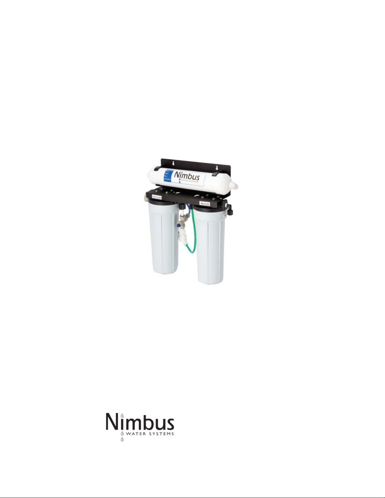
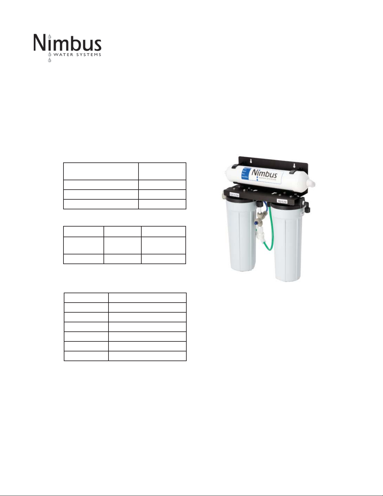
Nimbus CS-2
Reverse Osmosis System
41840 McAlby Court, Suite A
Murrieta, CA 92562
800-451-9343, FAX 951-894-2801
www.nimbuswater.com
41840-A McAlby Court, Murrieta, CA 92562
(800) 451-9343, www.nimbuswater.com
REV: 0507
05/09
1
Page 2

41840-A McAlby Court, Murrieta, CA 92562
(800) 451-9343, www.nimbuswater.com
2
Page 3
Introduc on to the CS-2
Congratula ons on your purchase of the Nimbus CS-2 reverse osmosis system. When properly maintained, this system will
provide you with years of trouble-free service. The next sec ons contain important informa on on the proper care and
maintenance of your system, please take a few minutes to read through this informa on.
The cartridges in this system must be replaced on a regular basis to maintain effi ciency and to safeguard water quality.
These cartridges work together to remove poten al contaminants from your tap water and must be replaced every 6-12
months. Any signifi cant change in performance of the system should be inves gated promptly to avoid secondary damage
or deteriora on to other parts of the system.
Replacement Cartridges
Descrip on
RO Membrane Desalinator 12 months
Pre-fi lter 6-12 months
Post-Filter 12 months
System Specifi ca ons
Membrane System w/Tank
Produc on 36 GPD
(136.3 LPD)
TDS Rejec on 95% 95%
Tested at 60 psig (4 bar), 500ppm TDS municipal water, 77°F
(25°C)
Replacement
Interval
11.3 GPD
(42.8LPD)
Feed Water Requirements
Pressure 40-80 psi (275 kPa - 552 kPa)
Temperature 40°F - 100°F (4°C - 38°C)
TDS <2000 mg/L
Chlorine <1.0 mg/L
NTU <1
SDI <5
pH 4-8
Feed water must be potable, municipal water. Must be free
of poten al membrane foulants such as Iron, Hydrogen
Sulfi de and Manganese.
41840-A McAlby Court, Murrieta, CA 92562
(800) 451-9343, www.nimbuswater.com
3
Page 4

Warranty
The Limited Warranty extends to the original purchaser of the system. This warranty covers all parts and factory labor needed to repair any Manufacturer-supplied item that proves to be defec ve in material, workman ship or factory prepara on. The above-men oned warranty ap plies for
the fi rst full calender year from date of purchase. These defec ve items are subject to the following exclusions: membranes, fi lters, O-rings, and all
other parts or components that require regular replacement as a result of ordinary usage.
Disclaimers This Warranty applies only if the system is installed and used in compliance with the instruc ons enclosed with the sys tem.
This Warranty does not cover the costs of repairs or adjustments to the unit that may be needed because of the use of improper parts, equipment
or materials. This Warranty does not cover repairs required due to unauthorized altera ons of the unit, or failure of a unit caused by such altera-
ons or by unauthorized repairs.
The Warranty does not cover malfunc ons of the unit due to tampering, misuse, altera on, lack of regular mainte nance, misapplica on, fouling due
to hydrogen sulfi de or iron, scaling from excessive hardness, turbidity greater than 1.0 NTU, Silt Density Index (SDI) greater than 5.0 SDI, or excessive
membrane hydrolysis due to chlorine levels in excess of 0.5 ppm. In addi on, damage to the unit due to fi re, accident, negligence, act of God, or
events beyond the control of the Manufacturer are not covered by this warranty.
Incidental and Consequen al Damages The Manufacturer does not assume responsibility for payment of inci dental and consequen al damages as
a result of the failure of this unit to comply with express or implied warran es, such as lost me, inconvenience, damage to personal property, loss
of revenue, commercial losses, postage, travel, telephone expendi tures, or other losses of this nature. Some states do not allow the exclusion or
limita on of incidental or consequen al dam ages, so this exclusion may not apply to you.
Owner’s Warranty Responsibili es Under the provisions of the Warranty, the owner is expected to schedule maintenance, as de scribed in this
Manual. Neglect, improper mainte nance, abuse, or unapproved modifi ca ons may invalidate the Warranty. Should your unit develop a defect or
otherwise fail to perform in accordance with this warranty, you should contact the dealer from whom the product was originally purchased.
Implied Warran es The implied at-law warran es of merchantability and fi tness for a par cular purpose shall terminate on the date one year a er the
date of purchase. Note: some states do not allow limita ons on how long an implied warranty lasts, so the above limita ons may not apply to you.
Other Rights This Warranty gives you specifi c legal rights and you may also have other rights which vary from state to state.
Please fi ll out the form below and retain for future reference.
Model:
Nimbus CS-2
Date Code:
Install Date:
Sold by:
Installed By:
Service Center
Phone Number:
41840-A McAlby Court, Murrieta, CA 92562
(800) 451-9343, www.nimbuswater.com
4
Page 5

Typical Installa on Diagram
A. Product water storage tank
B. Tank shut-off valve
C. Tank tubing
D
F
E
G
F
I
M
O
H
N
B
JK
L
C
D. Air-gap faucet
E. Drain connec on assembly
F. Drain tubing
G. Quick-connect fi ng
H. Product water tubing
I. Membrane desalinator
J. Carbon post-fi lter
K. Sediment/carbon pre-fi lter
L. Automa c shut-off valve
M. Inlet fi ng
N. Feed water tubing
O. Feed water shut-off
A
This system has been designed for installa on by a licensed professional such as a contractor or plumber. Proper comple on of this installa-
on will require basic familiarity with standard sink plumbing and proper use of common hand and power tools. Improperly installed systems
could result in water damage due to leaks or fl ooding. Do not use with water that is microbiologically unsafe.
41840-A McAlby Court, Murrieta, CA 92562
(800) 451-9343, www.nimbuswater.com
5
Page 6

CS-2 Push Handle Faucet
For easier installa on, a ach all tubing prior to moun ng the
faucet.
1. Insert polished faucet base onto base of faucet.
2. Push the 1/4” drain tubing onto the 1/4” barb fi ng. This tube
must be of suffi cient length to reach the white swivel with yellow
collet on the membrane desalinator.
3. Push the 3/8” tubing onto the larger 3/8” barbed fi ng, being
sure you have enough tubing to reach the drain saddle.
4. Slip the 1/4" and 3/8" tubing though opening in polished faucet
base. Slide white plas c spacer open-end-up onto the threaded
faucet stem (2).
5. Thread the 3/8" washer (3) and moun ng lock nut (4) onto the
threaded stem. (Fig 6)
6. Thread faucet quick-connect adapter (5) on to threads of faucet
stem. NOTE: This connec on should be hand- ghtened only. Push
one end of product tubing into connec on.
7. Insert tubing and faucet assembly down through the sink hole.
8. Posi on the faucet to the desired handle orienta on. Slip the
slo ed washer (1) between the white plas c spacer and the sink.
Securely hand ghten the moun ng nut.
Airgap to system drain
(1/4" tubing)
Metal base plate
Rubber seal
Faucet to drain
saddle (3/8" tubing)
Product water
(1/4" tubing)
1
2
3
4
5
9. Connect the 3/8” tubing to the drain saddle assembly using the
drain connector nut supplied. This tubing should follow as direct a
path as possible; long runs, looping or deep sags will restrict normal brine fl ow to the drain. Save the unused por on of the tubing
for the installa on of the storage tank.
10. Apply a small amount of silicone-based lubricant to the O-rings
located at the base of the spout. Firmly insert spout assembly into
the top hole of faucet body (approximately 1/4"). You may swivel
the faucet le or right.
41840-A McAlby Court, Murrieta, CA 92562
(800) 451-9343, www.nimbuswater.com
Connect to product
water tubing
6
Page 7

CS-2 Feed and Drain Connec ons
Feed Connec on
1. Locate and turn off the angle stop valve on the cold water line feeding the sink where
the system is to be installed. This valve will usually be located under the sink on the
pipe coming out of the wall.
2. When the angle stop valve is closed, relieve pressure in the line by opening the cold
water tap on the sink.
3. To install the feed adapter at the faucet connector, disconnect the cold water feed line
where it connects to the faucet inlet connector. This will usually require an open end
wrench, pliers, or long reach faucet wrench.
4. Take the 1/4" feed connector from the parts kit and install it into the brass feed connector adapter. Use a crescent wrench or open-end wrench to ghten the connector
into the adapter. See Fig. 2.
5. Using the fl at and cone washers as neces sary, install the feed adapter into the faucet
inlet connector. Then reconnect the cold water feed line to the open end of the feed
adapter. Tighten all connec ons securely.
6. Using the 1/4" tubing, install the compression nut, plas c ferrule, and plas c tube
insert. Secure the tubing into the feed connector. Tighten the tubing retain ing nut
securely.
Fig. 2
7. Obtain the small feed valve warning tag from the parts bag and a ach it by its wire
es to the feed valve.
Drain Connec on
Note: The drain saddle assembly must be installed before the 'P' trap. Do not install the
drain saddle assembly between the 'P' trap and the wall.
1. Posi on drain saddle assembly (Fig. 3) on drain pipe under sink between the P trap
and the sink connec on.
2. Orient the drain saddle so that the connec tor opening points in the general direc on
of the planned loca on for the R.O. dispensing faucet.
3. Screw the connector nut onto the drain saddle threaded connector loosely (Fig. 4).
Using the connector opening in the side of the drain saddle as a guide, drill a 3/8" hole
through the wall of the drain pipe.
4. Remove drain saddle assembly. Place the adhesive foam pad over the 3/8" hole in
the drain pipe. Replace the assembly onto the drain pipe, aligning the hole in the drain
with the hole in the drain assembly.
5. Tighten the saddle bolts evenly on both sides un l the saddle grips the pipe snugly -
do not over ghten. (Fig.4)
Fig. 3
Fig. 4
41840-A McAlby Court, Murrieta, CA 92562
(800) 451-9343, www.nimbuswater.com
7
Page 8

CS-2 Tubing Connec ons
1. Measure and cut a length of 1/4" or 3/8" tubing (depending on model) long enough to reach from the faucet to the
faucet connector on the system. Connect one end to the faucet nipple using a jaco nut and plas c insert. Connect the other
end to the faucet connec on on the post-fi lter suing a jaco nut and plas c insert.
2. Measure and cut the length of 1/4" tubing long enough to reach from the feed water supply to the inlet. Connect the
end to the feed inlet on the prefi lter using a jaco nut and plas c insert. See Fig. 5.
3. Connect one end of a 3/8" length of tubing to the tank valve. Insert the other end fi rmly into the quick-connect cross on
the shut-off valve.
4. Connect the 1/4" tubing from the faucet to the white swivel with yellow collet on the membrane desalinator.
5. Connect the free end of the 3/8" drain tubing to the drain connec on.
COMPRESSION NUT
INSERT
TUBING
FERRULE
Fig. 5
41840-A McAlby Court, Murrieta, CA 92562
(800) 451-9343, www.nimbuswater.com
8
Page 9

Ac va on and Flushing
System Ac va on and Inspec on
1. Check all tubing connec ons to ensure they are fi rmly seated and secure.
2. Open the dispensing faucet at the sink. Close the tank shut-off valve.
3. Open the feed water valve to the system. Observe all tubing and connec ons for several minutes to detect any leaks.
In approximately 5 minutes, (assuming normal feed water pressure) the dispensing faucet should begin dripping.
4. Place a pan or other tempo rary water basin near the drain 'P' trap. Loosen the connector nut holding the 3/8" tube
in the drain saddle connec tor. Pull the tube out of the connector and use the pan to catch any water that may spill. Brine
water should be fl owing from the tube. Reconnect the tube to the drain saddle and hand- ght en the connector nut.
5. Allow the faucet the run for up to 15 minutes, then close the faucet.
6. Check for leaks at all connec ons.
7. Open the tank shut-off valve.
Ini al Flushing Procedure
1. Before the system can be used for drinking water produc on it must be adequately fl ushed. Each reservoir tank is
dosed with a small amount of powdered sani zer before shipment, typically a chlorina ng agent, in order to ensure tank
internal cleanliness. Also, the carbon fi lter cartridge will release a small amount of carbon fi nes during the fi rst tankful of
fl ow. This fl ushing procedure will allow any sani zer or carbon fi nes to pass from the system.
2. Ini al tank fi lling will take approximately one hour (based on average feed pressure). When the tank is full, the water
pressure will have risen to the point where the automa c shut-off valve inside the system will stop the feed fl ow through
the system. Actua on of the automa c shut-off valve can be determined by either checking for a lack of brine fl ow to the
drain saddle, or by listening very closely near the dispensing faucet for absence of water fl ow sound though the air gap.
When the tank has fi lled for the fi rst me, it should be le undisturbed for at least 8 hours to ensure proper sani za on.
3. A er 8 hours has elapsed, open the dispensing faucet fully and allow the product water to run out to drain at maximum
fl ow. The ini al discharge will be dark with the bulk of the carbon par cle wash out. There may also be the scent of chlo-
rinated water from the sani zing agent. When the fl ow has diminished to a fast drip or small stream, close the dispensing
faucet.
4. Fill and fl ush the tank at least three mes prior to use. If necessary, repeat un l the chlorina on scent has disappeared.
It is important that the fl ush be done at maximum fl ow (e.g. the tank must be full) to assist in rapid wash out. A er this
fl ushing procedure the system is ready for normal use.
41840-A McAlby Court, Murrieta, CA 92562
(800) 451-9343, www.nimbuswater.com
9
Page 10

CS-2 Installa on Checklist
1. System is located where it will not be subject to physical impacts or rough contact by heavy objects.
2. Feed water pressure to the unit is no less than 40 psi and no greater than 80 PSI.
3. All tubing connec ons, especially push-in quick connec ons, are fully inserted.
4. Tubing connected between the faucet and the drain saddle fi ng (the fi ng a ached to the sink drain pipe) runs
"downhill" to the drain. There should be no loops or places where water would not fl ow out to the drain.
5. Feed water valve is open.
6. Within one to two hours a er ini al applica on of water pressure, check again for leaks especially at the tank, faucet
tubing and connectors. These parts will not see full pressure un l approximately 2 hours a er the system is ac vated.
7. Flush three tankfuls of product water to drain. If a chlorine scent persists, repeat fl ushing procedure.
41840-A McAlby Court, Murrieta, CA 92562
(800) 451-9343, www.nimbuswater.com
10
Page 11

CS-2 Maintenance
Desalinator Replacement
1. Close the feed water shut-off valve and close the tank shut-off valve.
2. Open the dispensing faucet to relieve system pressure. Close dispensing faucet when fl ow has stopped.
3. Remove old desalinator from clips on frame. Install new desalinator
on frame.
4. Remove feed tube from old desalinator and insert it in the (green)
feed connector of the new desalinator. See Figure 6.
5. Repeat tube removal and replacement steps for product and drain
tubes.
6. Turn on feed water shut-off valve and open dispensing faucet.
To Drain
(Yellow Collet)
7. Close dispensing faucet a er water starts running.
8. Observe system for any leaks, especially at newly re placed cartridge.
9. Open the tank shut-off valve.
10. The system should be fl ushed at least once as described above under
Sec on 8.
Filter Replacement
1. Close the feed water shut-off valve and close the tank shut-off valve.
2. Open the dispensing faucet to relieve system pressure. Close dispensing faucet when fl ow has stopped.
3. Remove the prefi lter housing by turning it clockwise (when viewed
from above). Remove old prefi lter from housing and discard. Remove
O-ring from top of housing. Wash O-ring and housing. Replace O-ring in
groove at top of housing. Insert new fi lter. Replace housing into cap by
turning counter clockwise. (When viewed from above).
4. Repeat Step 5 for pos ilter.
5. Turn on the feed water valve and open the tank shut-off valve.
Product
(Blue Collet)
Feed
(Green Collet)
Fig. 6
6. Observe system for any leaks, especially at newly re placed cartridge.
7. The system should be fl ushed at least once as described in System
Ac va on and Flushing.
41840-A McAlby Court, Murrieta, CA 92562
(800) 451-9343, www.nimbuswater.com
11
 Loading...