

Page 1
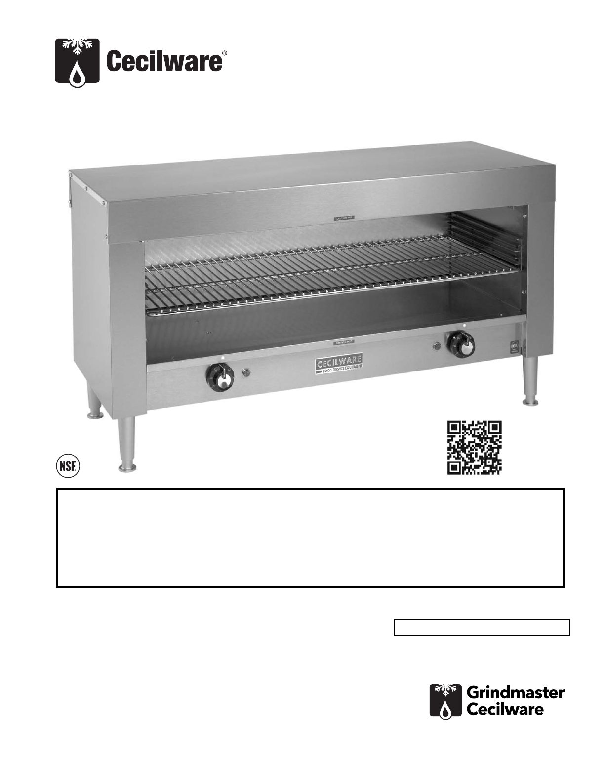
Electric Cheesemelter
Operator Manual
CM24M, CM24Q, CM36M, CM36Q
Grindmaster-Cecilware
4003 Collins Lane, Louisville, KY 40245 USA
Phone: 502.425.4776 Toll Free: 800.695.4500
Fax: 502.425.4664
Web: gmcw.com Email: info@gmcw.com
Safety Information .....................................2
Unpacking...................................................2
Installation..................................................2
Operation....................................................3
Cleaning......................................................3
Maintenance...............................................3
Parts Diagram and List ...............................4
Wiring Diagram..........................................4
Thank you for purchasing this quality Cheesemelter. For your safety and the safety of others, read all
warnings and the operator’s manual before installing or using the product. Properly instruct all operators.
Keep training records. For future reference, record serial number here:
Table of Contents
©2017 Grindmaster-Cecilware
Printed in USA
0417 Form # CW-341-02
Part # 390-00088
Grindmaster-Cecilware provides the
industry’s BEST warranty. Visit gmcw.com
for warranty terms and conditions.
Model:
Activate your warranty now at
http://gmcw.com/warranty-registration
Page 2

2 Cecilware
®
Electric Cheesemelter
Important Safety Information
This is the safety alert symbol. It is used to alert you to potential personal injury hazards. Obey all safety messages
that follow this symbol to avoid possible injury or death.
WARNING
• Do not deform power cord.
• Follow national and local electrical codes.
• Do not store or use gasoline or other flammable vapors and liquids in the vicinity of this or any other
appliance.
• Use only on a dedicated circuit load that is properly protected and capable of the rated load. Do not use
extension cords, as this could result in electrical shock, overheating, and fire.
• Risk of electrical shock. Disconnect power before servicing or cleaning unit. Contact Grindmaster-Cecilware
Technical Service for service assistance.
• If the supply cord is damaged, it must be replaced by the manufacturer, its service agents or similarly
qualified persons in order to avoid a hazard.
FAILURE TO COMPLY TO THE ABOVE RISKS PERSONAL INJURY, SHOCK HAZARD, FIRE, OR DAMAGE TO
EQUIPMENT.
CAUTION
• Read and understand the operating instructions in this manual thoroughly. Only allow properly trained
persons to operate this machine.
• Stay alert at all times during operation.
• Operate with care. Surfaces will get very hot and may cause serious burns.
• Keep operating area clean.
For your safety and the safety of others, read all warnings and the operator’s manual before installing or using
the product.
DANGER: This term warns the user of imminent hazard that will result in serious injury or death.
WARNING: This term refers to a potential hazard or unsafe practice, which could result in serious injury or
death.
CAUTION: This term refers to a potential hazard or unsafe practice, which could result in minor or moderate
injury.
NOTICE: This term refers to information that needs special attention or must be fully understood.
Unpacking
Carefully lift unit out of shipping container, and inspect
immediately for shipping damage. Your Cheesemelter
was shipped in a carton designed to give it maximum
protection. It was thoroughly inspected before leaving
the factory. File any claims for shipping damage or
irregularities directly with the carrier.
Installation
Mechanical Installation
Counter location: Select a suitable location for your
cheesemelter and adjust the leveling legs on the
bottom of the unit to level it and prevent rocking.
Height may be adjusted by turning the feet up or down
as desired.
Pass-thru location: Remove the outer and inner back
panels and adjust the leveling legs.
Wall mounted: Remove the outer back panel and
mount the wall brackets to the back of the unit using
the same screws. Refer to diagram on page 4. Position
the Cheesemelter on the wall and mark the four holes
through the mounting brackets on the wall. Use 5/16”
diameter toggle bolts 2" long or an equivalent fastener
to mount the unit to the wall.
Safety Information
NOTICE
Page 3

Electric Cheesemelter Cecilware
®
3
Electrical Installation
CM24M and CM24Q: provide a suitable 120V - 15A
wall outlet.
CM36M and CM36Q:
FOR QUALIFIED SERVICE PERSONS ONLY
Before connecting the unit, read the electrical
specification label. Verify that the power supply
available matches the information on this label.
Remove the cover from the field wiring compartment
located on the bottom of the Cheesemelter. Use a
suitable conduit fitting and connect two #10 wires from
the power source to terminal L1 and L2 of the terminal
block and a ground wire to the grounding lug marked
GND. Refer to Wiring Diagram next page.
Operation
Apply power to the unit and turn the infinite switch
knob(s) to the high position. Allow a few minutes for
the element(s) to reach operating temperature. Place
the wire rack at the desired level and the cheesemelter
is ready to operate. Adjust the knob(s) for the proper
heat and adjust the rack for the type of food you are
preparing.
Cleaning
Use a mild detergent on the stainless exterior and a
commercial cleaner for the oven compartment.
Maintenance
FOR QUALIFIED SERVICE PERSONS ONLY
Problem: Element(s) do not heat when control(s) are
turned on.
Possible Cause: Loss of power to cheesemelter.
Remedy: Check fuses or reset circuit breakers from
power source.
Problem: One or more element(s) of cheesemelter fail
to heat up with infinite switch and pilot on. Possible
Cause: Element is burned out and should be replaced.
Replace as follows: (See diagram next page)
A - Metal Sheath Elements
.
1. Turn off power to cheesemelter.
2. Remove one screw from each element
bracket and rotate bracket (11) to clear
element.
3. Remove the two screws holding the
element to the side panel and withdraw the
element. Remove the two wires from the
element being careful that the wires do not
fall behind the panel.
4. Replace the element in the reverse order of
removal.
B - Quartz Tube Element.-
1. Remove quartz element bracket mounting
screws from one side of the cheesemelter.
2. Lower the bracket (9) to clear the quartz
elements and withdraw the guard rods (10)
from the other bracket.
3. Remove the other bracket.
4. Slide the element (1 A) to one side to clear
the side panel and withdraw the element to
the front of the cheesemelter. Remove the
quick disconnect terminals from the
defective element and replace it with a new
one.
5. Reinstall components in the reverse order of
removal.
NOTICE: Be certain the replacement quartz element
is of the same wattage and voltage as the one it's
replacing.
Problem: Element(s) do not heat and pilot light related
to the element(s) does not light.
Possible Cause: Infinite control not operating and
should be replaced.
Remedy: Replace infinite control as follows:
1. Remove bottom cover of cheesemelter.
2. Remove knob and nut from infinite control
and withdraw from front panel.
3. Disconnect wires from faulty control and
replace it with a new one.
4. Assemble the parts in the reverse order of
removal. Refer to diagram next page for
correct connections to control.
If you need help, call Grindmaster-Cecilware Technical
Service Department, (502) 425-4776 or (800) 695-4500
(USA & Canada only) (Monday through Friday 8 AM - 6
PM EST). Please have the model and serial number
ready so that accurate information can be given.
Prior authorization must be obtained from
Grindmaster- Cecilware for all warranty claims.
Grindmaster-Cecilware provides the industry’s
BEST warranty. Visit our website at GMCW.com
for warranty terms and conditions.
WARNING: Electrical shock hazard. Make sure
main disconnect is off before connecting unit.
CAUTION: To avoid burns, allow unit to cool
before cleaning.
CAUTION: Disconnect power from unit before
attempting electrical repairs.
Installation (continued)
Page 4
Grindmaster-Cecilware
4003 Collins Lane, Louisville, KY 40245 USA
Phone: 502.425.4776 Toll Free: 800.695.4500
Fax: 502.425.4664
Web: gmcw.com Email: info@gmcw.com
©2017 Grindmaster-Cecilware
Printed in USA
0417 Form # CW-341-02
Part # 390-00088
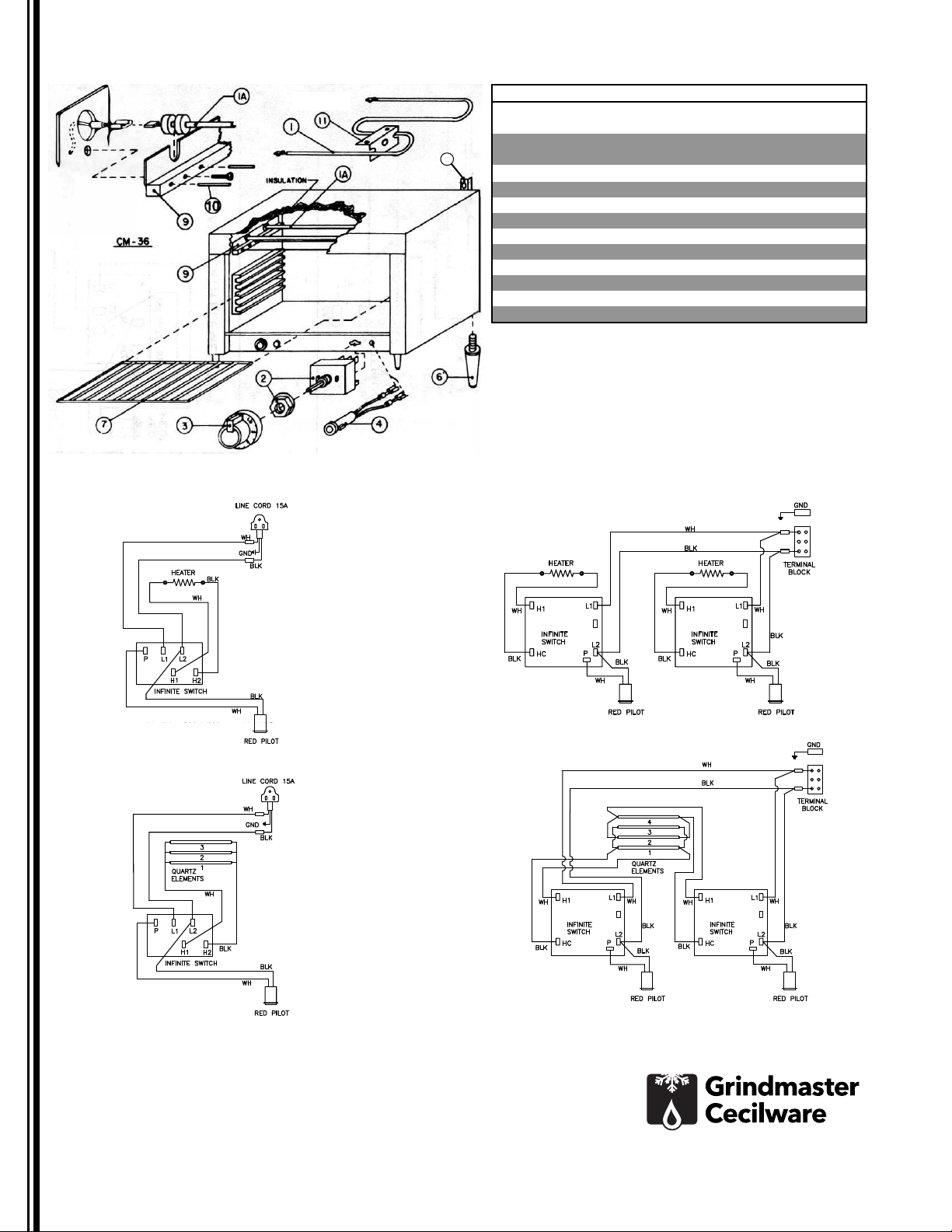
Wiring Diagram
Parts Diagram and List
8
CM-24M WIRING DIAGRAM FOR
METAL SHEATH ELEMENTS
CM-24Q WIRING DIAGRAM FOR
QUARTZ TUBE ELEMENTS
CM-36M WIRING DIAGRAM FOR
METAL SHEATH ELEMENTS
CM-36Q WIRING DIAGRAM FOR
QUARTZ TUBE ELEMENTS
Description CM24M CM24Q CM36M CM36Q
1
208V/240V 1500W Heating Element
G101A
120V 1500W Heating Element 320-00064
1A
208V/240V 900W Quartz Element
G191A
120V 500W Quartz Element 320-00065
2
Infinite Switch 344-00035 344-00035 344-00055 344-00055
3
Infinite Switch Knob
M060A M060A M060A M060A
4
Pilot Light
C164A C164A C164A C164A
5
Line Cord
C032A C032A
6
Adjustable Legs
71256 71256 71256 71256
7
Wire Rack
S080A S080A S079A S079A
8
Bracket Wall Mount (Optional)
U345AL U345AL U345AL U345AL
9
Quartz Element Brackets
U467A U467A
10
Rod Guard
V158A V159A
11
Element Bracket
U301A U301A
 Loading...