

Page 1
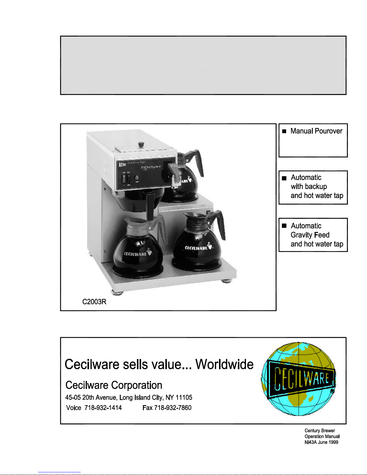
Century 2000
Low Profile Coffee Brewers
Page 2

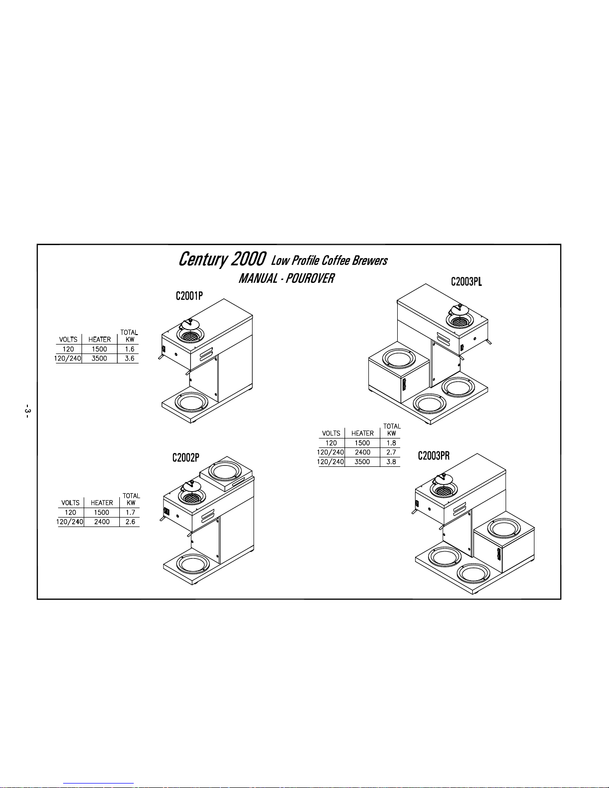
CENTURY 2000 COFFEE BREWERS
Manual Pourover Group - 120V
MODEL WARMERS VOLTS
C-2001P 1 BOTTOM 120 1.6 15 8.00 17.35 17.25
C-2002P 1 TOP, 1 BOTTOM 120 1.7 15 8.00 17.25 19.00
C-2003P 2 TOP, 1 BOTTOM 120 1.8 15 8.00 17.25 19.00
C-2003PR 2 BOTTOM, 1 RIGHT 120 1.8 15 16.00 17.25 17.25
C-2003PL 2 BOTTOM, 1 LEFT 120 1.8 15 16.00 17.25 17.25
TOTAL
KW
AMPS W D H
Dimensions (inches)
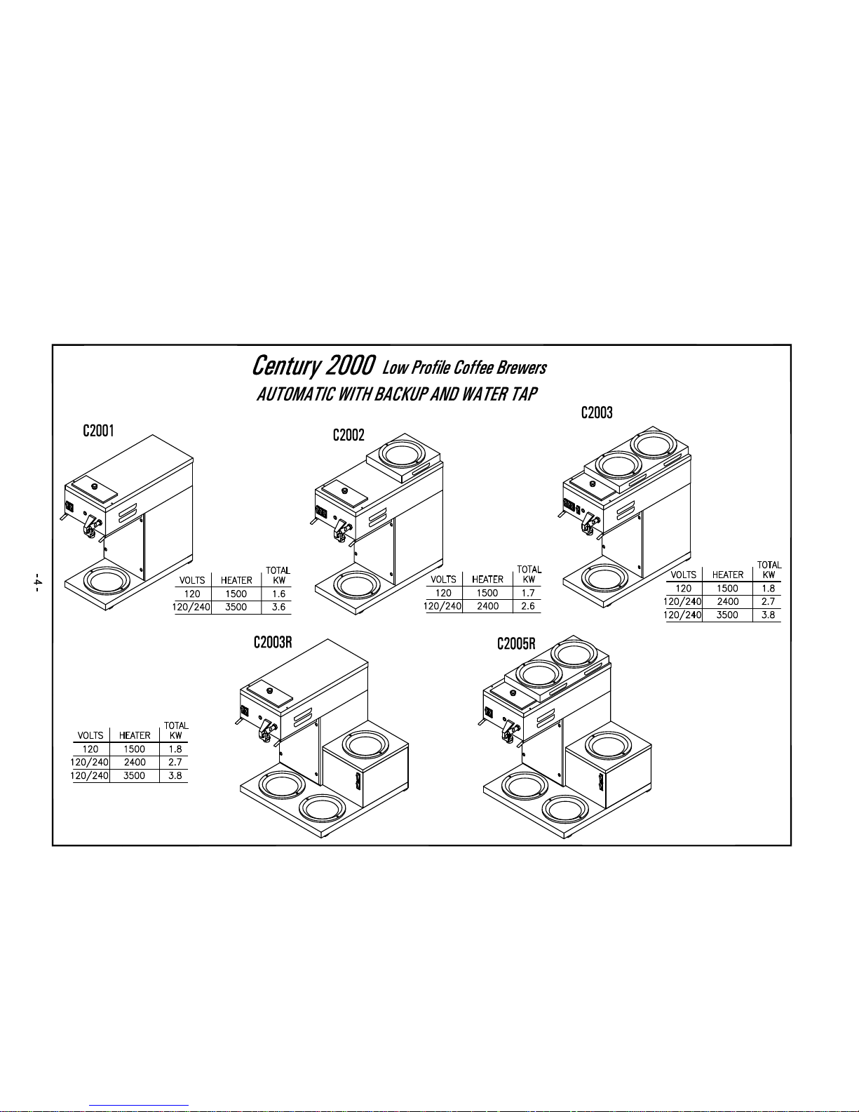
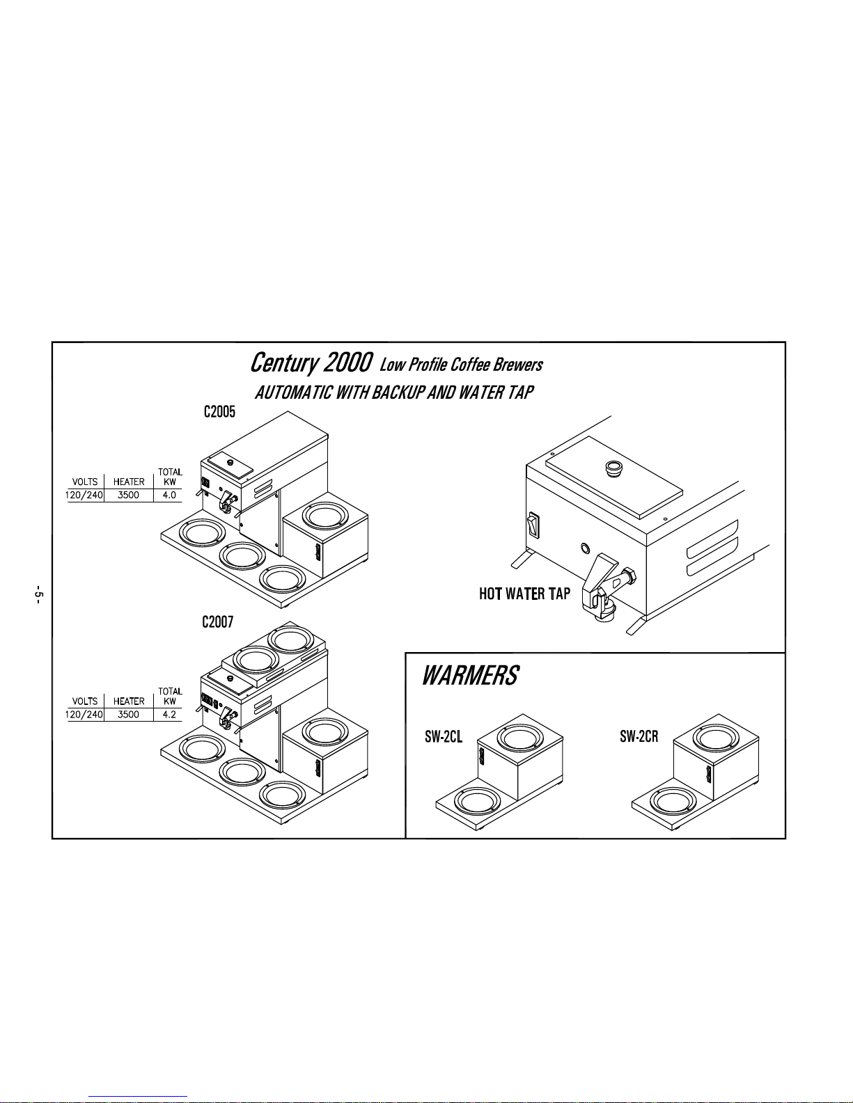
Automatic with Backup Group - 120V
C-2001 1 BOTTOM 120 1.6 15 8.00 17.25 17.25
C-2002 1 TOP, 1 BOTTOM 120 1.7 15 8.00 17.25 19.00
C-2003 2 TOP, 1 BOTTOM 120 1.8 15 8.00 17.25 19.00
C-2003R 2 BOTTOM, 1 RIGHT 120 1.8 15 16.00 17.25 17.25
C-2003L 2 BOTTOM, 1 LEFT 120 1.8 15 16.00 17.25 17.25
Automatic with Backup Group - 120/240V
C-2003R-35 2 BOTTOM, 1 RIGHT 120/240 3.8 20 16.00 17.25 17.25
C-2003L-35 2 BOTTOM, 1 LEFT 120/240 3.8 20 16.00 17.25 17.25
C-2005R-35 2 TOP, 3 BOTTOM RT. 120/240 4.0 20 16.00 17.25 19.00
C-2005L-35 2 TOP, 3 BOTTOM LF. 120/240 4.0 20 16.00 17.25 19.00
C-2005-35 3 BOTTOM, 1 LF, 1 RT 120/240 4.0 20 24.00 17.25 17.25
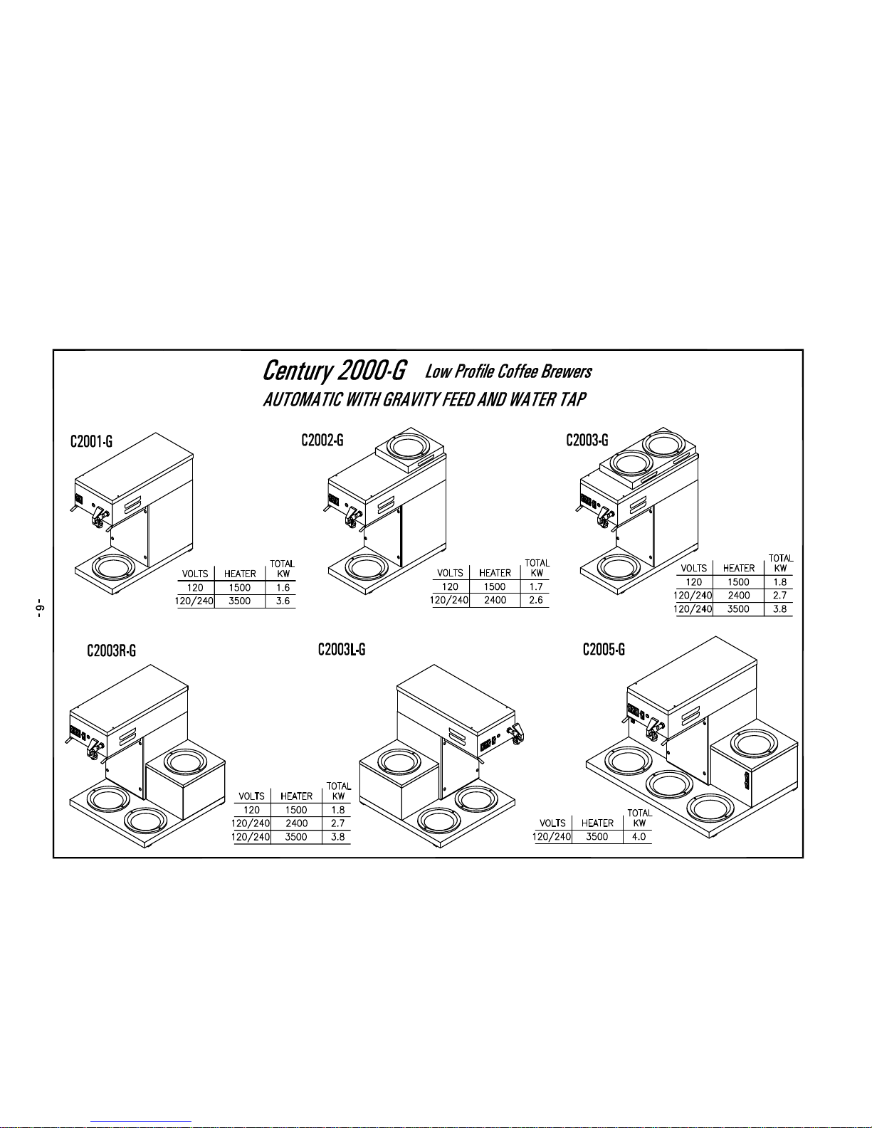
CENTURY 2000 COFFEE BREWERS
WITH GRAVITY FEED SYSTEM
Automatic with Gravity Feed Group - 120V
C-2001G 1 BOTTOM 120 1.6 15 8.00 17.35 17.25
C-2002G 1 TOP, 1 BOTTOM 120 1.7 15 8.00 17.25 19.00
C-2003G 2 TOP, 1 BOTTOM 120 1.8 15 8.00 17.25 19.00
C-2003RG 2 BOTTOM, 1 RIGHT 120 1.8 15 16.00 17.25 17.25
C-2003LG 2 BOTTOM, 1 LEFT 120 1.8 15 16.00 17.25 17.25
Automatic with Gravity Feed Group - 120/240V
C-2003RG-35 2 BOTTOM, 1 RIGHT 120/240 3.8 20 16.00 17.25 17.25
C-2003LG-35 2 BOTTOM, 1 LEFT 120/240 3.8 20 16.00 17.25 17.25
C-2005G-35 2 TOP, 3 BOTTOM 120/240 4.0 20 24.00 17.25 19.00
C-2005RG-35 2 TOP, 3 BOTTOM 120/240 4.0 20 24.00 17.25 19.00
C-2005LG-35 2 TOP, 3 BOTTOM 120/240 4.0 20 24.00 17.25 19.00
For export voltage 220 Volts, 50 Cycles, 1 Phase , add Suffix "X" to model number
Man-page1.xls
1
Page 3

Page 4
Page 5
Page 6
Page 7
Page 8
1
17
2
16
3
15
4
14
5
13
6
12
7
8
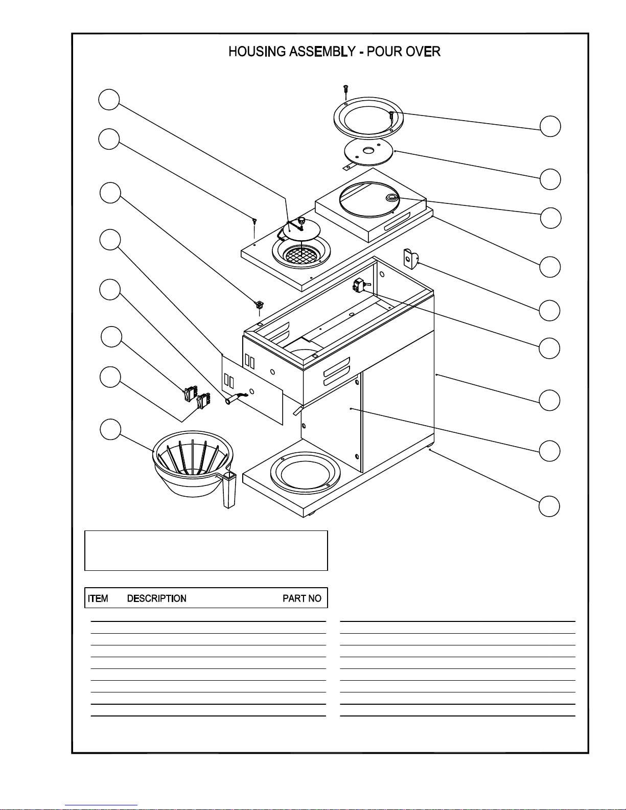
PARTS LIST
COVER, POUROVER
1
SCREW, TRUSS HEAD SL #8x3/8
2
NYLON RECEPTACLE #8
3
LABEL, SWITCH PANEL
4
READY LIGHT - GREEN
5
POWER SWITCH - RED
6
WARMER SWITCH, AMBER
7
BREW BASKET - BLACK
8
LEGS 3/4" ADJUSTABLE
9
U588Q
P489A
M408A
NF08A
C072A
L217A
L580A
V001A
10
11
12
13
14
15
16
17
TOWER COVER
BODY WELDMENT ASSEMBLY
HEATER SWITCH SPST
TOGGLE SWITCH BRACKET
TOP COVER W/SINGLE WARMER ASSY
GROMMET, 5/8 I.D.
WARMER DISH & ELEMENT 120V
WARMER DISH & ELEMENT 220V
SCREW FLAT HD # 8 x 3/4
11
10
9
R958A
R960Q
L069A
U81OC
RS32Q
M090A
G095A
G107A
P139AM042A
- 7 -
Page 9

1
20
5
6
7
8
9
21
2
3
19
18
17
4
16
15
14
13
12
11
PARTS LIST
DESCRIPTIONITEM
TROUGH SUB-ASSY
1 RP97Q
SPRAY TUBE ASSY
2
WASHER
3
WASHER, RED SILICON
4
SPRAY HEAD ADAPTER
5
SPRAY HEAD
6
BRACKET, COMPONENT
7
TERMINAL BLOCK, 3 POSITION
8
ELBOW 90°
9
10
11
12
SILICON TUBE 1/2" ID, 14" LG
PLUG
TANK BODY
PART NO
H297Q
P155A
M197A
K107A
E004A
RS45A
B171A
K525A
M611A
M488A
RK48Q
- 8 -
13
14
15
16
17
18
19
20
21
HEATER, 120V 1500W
HEATER, 220V 2400W
HEATER, 240V 3500W
HEX NUT 1/4-18 x 3/4
SILICON GASKET
TANK TOP
HI-LIMIT RETAINER
HI-LIMIT
DIRECT MOUNTING SEAL (.466I.D.)
THERMOSTAT
TROUGH SOCKET
10
G296A
G298A
G297A
K207A
M498A
RQ74A
RR45A
L573A
M461A
L002A
CD77A
Page 10

15
16
181719
24
25
14
13
12
11
10
26
27
28
29
20
21
22
23
3
30
9
31
8
7
PARTS LIST
ITEM
DESCRIPTION
TUBING 1/4" COLD WATER INLET
1
TUBING 1/4", NEEDLE VALVE EXT.
2
NEEDLE VALVE (80242)
3
MT. BKT, WATER INLET VALVE
4
HOSE NUT FITTING
5
VALVE, WATER INLET (.75GPM) 120V
6
VALVE, WATER INLET (.75GPM) 220V
UNION "TEE" 1/4"
7
WATER COIL SUB-ASSY
8
GASKET, SILICONE RUBBER
9
FLAT WASHER
10
FAUCET ASSEMBLY
11
TUBING 1/4" HOT WATER OUTLET
12
TUBING 1/4" TANK INLET
13
TROUGH SUB-ASSEMBLY
14
SILICONE SEAL, 12mm (0.466 I.D.)
15
ELBOW 90°
16
DRAIN PLUG
17
SILICONE TUBING, 1/2" I.D. 14" LG
18
46 5 2
PART NO
H328Q
H334Q
L006A
RQ52A
K491A
L588A
L594A
K568A
H182Q
M121A
P175A
D046A
H327Q
H329Q
RP97Q
M461A
K525A
M488A
M611A
1 34 32 16
33
SPRAY TUBE ASSEMBLY
19
WASHER
20
WASHER, RED SILICON
21
SPRAY HEAD ADAPTER
22
SPRAY HEAD
23
THERMOSTAT
24
SILICON TUBING, 4mm (6" LG)
25
NYLON FITTING, AIR LOCK
26
HI-LIMIT, 226°F CUTOUT
27
TANK TOP W/COIL
28
SILICONE GASKET
29
HEATER (120V - 1.5KW)
30
HEATER (240V - 3.5KW)
HEATER (220V - 2.4KW)
TANK, WELDED SUB-ASSY
31
TIMER 120V 2 MIN
32
TIMER 240V 2 MIN
BKT, COMPONENT W/TIMER
33
TERMINAL BLOCK, 3 POS
34
15
H297Q
P155A
M197A
K107A
E004A
L002A
M614A
K534A
L573A
RQ74A
M600A
G296A
G297A
G298A
RK48Q
L592A
L593A
RS11A
B171A
- 9 -
Page 11

5 6 7 8 9
10
11
4
3
2
1
24
23
22
12
CECILWARE
13
14
161718192021
15
PARTS LIST
ITEM
DESCRIPTION
SPRAY TUBE ASSEMBLY
1
TIMER HOT WATER DISPENSER
2
THERMOSTAT
3
THERMOSTAT KNOB
4
WATER LEVEL CONTROL
5
WATER LEVEL SENSOR
6
SILICONE GASKET
7
SCREW 1/4-20 x 5/8 S.S.
8
TANK TOP ASSEMBLY
9
WATER TANK SUB-ASSEMBLY
10
HEATER 120V - 1500W
11
HI-LIMIT
12
ELBOW 90°
13
PART NO
K642Q
L592A
L532L
M008A
L566A
K402Q
M600A
P465A
RV34Q
RV33Q
G356A
L573A
K525A
- 10 -
SILICONE TUBING 1/2" I.D. x 14" LONG
14
TUBING 1/4" COLD WATER INLET
15
MT. BKT, WATER INLET VALVE
16
HOSE NUT FITTING
17
VALVE, WATER INLET (.35GPM) 120V
VALVE, WATER INLET (.35GPM) 220V
18
19
FAUCET ASSEMBLY
SPRAY HEAD ADAPTER
20
SPRAY HEAD
21
DISPENSE VALVE 120V
22
SILICONE SEAL, 12mm (0.466 I.D.)
23
NOZZLE
24 K629A
M611A
H328Q
RQ52A
K491A
L588A
L594A
D085A
K107A
E004A
L596A
M461A
Page 12

WARNING:
MACHINE WARRANTY IS VOID IF MACHINE IS CONNECTED TO ANY VOLTAGE OTHER
THAN 120 VOLTS. (EXPORT UNITS SHOULD BE CONNECTED TO 220 VOLTS)
** INSTALLATION INSTRUCTIONS **
NOTE: A SEPARATE CIRCUIT SHOULD BE SUPPLIED FOR EACH OF THESE
BREWERS WITH A 15 AMP CIRCUIT BREAKER OR FUSE. CHECK
LOCAL CODES FOR COMPLIANCE IN INSTALLATION.
MANUAL POUROVER MODELS
Are not equipped with water inlet connections
AUTOMATIC WITH POUROVER BACKUP
Are equipped with a ¼" flare water inlet fitting which is located in the back of the unit.
WATER INLET CONNECTION:
HIGHLY RECOMMENDED: A water shut-off valve and a water filter, preferably a combination
charcoal / phosphate filter, to remove odors and inhibit lime and scale build up in the machine.
Note: In areas with extremely hard water, a water softener must be installed in order to prevent
malfunctioning of the equipment and in order not to void the warranty.
This equipment is to be installed to comply with the applicable federal, state, or local plumbing codes
having jurisdiction. In addition:
1. A quick disconnect water connection or enough extra coiled tubing (at least 2x the depth of the unit) so
that the machine can be moved for cleaning underneath.
2. An approved back flow prevention device, such as a double check valve to be installed between the
machine and the water supply.
CAUTION:
DO NOT CONNECT TO POWER SOURCE UNTIL AFTER PRIMING
These brewers are equipped with a rear Toggle Switch which controls the power to the tank heater.
Toggle Switch must be in the down or “OFF” position until step (3) is completed.
** PRIMING INSTRUCTIONS**
Man-page11-14.doc 11
Page 13

MANUAL POUROVER UNITS
THESE INSTRUCTIONS ARE FOR INITIAL PRIMING ONLY AND DO NOT HAVE TO BE
REPEATED FOR NORMAL OPERATION.
1. Remove sample filter pack from brew funnel and insert brew funnel back into machine.
2. Place an empty decanter on warmer plate directly under brew funnel.
3. Lift pourover cover and pour 4 decanters of cold water through the top opening at 3 minute
intervals. After the third decanter is poured, water will flow through spray head and funnel and fill
decanter beneath.
4. Plug line cord into receptacle and turn “ON” (TOGGLE UP) the heater switch, which is located in
the back, then turn on the power (and front warmer) switch which is located on the front panel. The
power switch light will light, indicating power is being applied to the machine. Wait approximately 15
minutes for the water to reach brewing temperature, at which point the green light comes on. You are
ready to brew coffee.
** BREWING INSTRUCTIONS **
MANUAL POUROVER UNITS
After initial priming has been completed
1. Insert brew funnel with filter and grounds into machine.
2. Place an empty decanter on warmer plate directly under brew funnel.
3. Lift pourover cover and pour one decanter of cold water through the top opening, coffee will be
ready in 3 1/2 minutes.
4. Remove grounds and filter as soon as coffee has dripped through. Never pour coffee back through
spent grounds.
** PRIMING AND BREWING INSTRUCTIONS**
AUTOMATIC GRAVITY FEED
THESE INSTRUCTIONS ARE FOR INITIAL PRIMING ONLY AND DO NOT HAVE TO BE
REPEATED FOR NORMAL OPERATION.
1. Remove sample filter pack from brew funnel and insert brew funnel back into machine.
2. Place an empty decanter on warmer plate directly under brew funnel.
3. Plug the power cord into a proper receptacle.
4. Activate the Power Switch. The Green Ready Light will go ON. The tank will start filling. Allow
approximately 4-5 minutes for the tank to fill.
5. After the water tank is filled, activate the Heater Switch. Allow approximately 20 minutes for the
water to reach a brew temperature (190°F). The heat up time will depend on the water inlet
temperature, the input voltage and the wattage of the elements in the machine.
When the (green) Ready Light comes on the machine is ready to start brewing.
The machine will only brew coffee after the Ready Light (green) goes ON.
6. Press Brew Button:
** CLEANING INSTRUCTIONS **
Man-page11-14.doc 12
Page 14

1. Wash brew funnel and decanter by hand as needed. Do not use dishwasher, which may cause
decanter breakage.
2. For cleaning all metal surfaces, use any reputable stainless steel cleaning compound.
Spray head should be checked and cleaned regularly. (At least once a week.) Spray head holes must be
kept open.
To prevent “LIMING” problems in the water tube, remove spray head and insert spring probe all
the way into the tank through the tube. When inserted into tank properly, no more than two inches of
spring should be visible. Push back and forth five or six times. This will keep tubes open and clear of
lime. In hard water areas, this should be done every day; this takes less than a minute.
SANITIZING:
All food dispensing units should be sanitized periodically. All parts to be sanitized must be cleaned
first.
To prepare a sanitizing solution:
ADD 2 TSP. OF LIQUID CLOROX BLEACH (5.25% CONCENTRATION) TO 1 GALLON OF
WATER AT ROOM TEMPERATURE (70° - 90°F).
Soak all parts for a minimum of 3 min. in the sanitizing solution.
Note: Always start with a unopened bottle of Clorox Bleach since the solution from an opened bottle
has a short life span.
Let all sanitized parts drain and dry naturally. DO NOT WIPE THEM DRY.
Before using the sanitized unit (or parts) with food stuffs, rinse all parts thoroughly with water.
CARE FOR STAINLESS STEEL:
Stainless Steel surfaces that come in contact with food substances, MUST BE CLEANED EVERY
DAY.
WHEN CLEANING STAINLESS STEEL , ONLY A pH NEUTRAL CLEANER IS TO BE USED.
Use nylon or brass brushes (not steel wire brushes) for removing food deposit.
Many food products contain acids,alkalies, or other substances which corrode Stainless Steel.
FOR AUTHORIZED SERVICE PERSONNEL ONLY
**SERVICE INSTRUCTIONS** and**TROUBLE SHOOTING GUIDE**
Man-page11-14.doc 13
Page 15

CAUTION: DISCONNECT POWER BEFORE ATTEMPTING ANY ELECTRICAL
REPAIRS
THERMOSTAT ADJUSTMENTS:
NOTE: The thermostat is behind the lower front panel. If water temperature is less than 197 degrees F
(92 degrees C) slowly turn thermostat knob clockwise until ready light goes out. When temperature of water
approaches 197 degrees to 203 degrees F (92 degrees to 95 degrees C) slowly turn thermostat knob counter-
clockwise until the green ready light comes on. If water temperature cannot be increased when thermostat knob is
turned fully clockwise, then proceed as follows:
Pull off knob. Place a small screwdriver into the center of thermostat shaft. While observing green ready light and
temperature on thermometer, hold shaft and turn small adjustment screw in center counter-clockwise until green
ready light goes out.When temperature of water approaches 197 degrees - 203 degrees F (92 degrees - 95 degrees
C), slowly turn screw clockwise until ready light comes on. Turning screw clockwise lowers temperature;
counter-clockwise raises it. After adjusting center screw, place nail polish or glyptol on screw to set in position.
NOTE: As a final check, measure water temperature at Spray Head . Temperature should be 197 degrees to
203 degrees F (92 degrees to 95 degrees C).
PROBLEMS WITH WARMER ELEMENTS & SWITCHES:
If warmer plate fails to heat, first check power source and then check if light on warmer switch is lit when in the
“ON” position. If warmer switch is lit, replace warmer plate by unplugging brewer, removing the two hold down
screws on plate and withdrawing warmer plate from brewer. Replace the new warmer plate. If warmer switch
does not light, replace it. To remove switch press each tab behind front plate of brewer down with screwdriver in
turn. As each tab is pressed, pop that corner of warmer switch out of the front of brewer. New switch snaps in
from the front.
IF WATER FAILS TO HEAT:
1. If Red power switch and warmer switches do not light, check heater switch in the back, toggle should be in the
up position . Check power supply outlet, replace fuse or reset circuit breaker if necessary. If power is good, check
rear heater switch for continuity and replace if switch stays open.
2. If water still fails to heat, disconnect line cord and check out tank heater, thermostat and high temperature
safety shutoff. Replace needed parts.
REPLACING HI-LIMIT SWITCH, THERMOSTAT, AND TANK HEATER
Unplug power cord, and remove top cover and lower front cover.
HI-LIMIT SWITCH Disconnect the (2) push-on leads, and pull out hi-limit. Replace switch
THERMOSTAT Loosen (2) screws securing thermostat to housing. Disconnect the push-on leads and
remove thermostat. Replace with new one in reverse order. When installing new control, do not overtighten small
packing nut on compression fitting.
TANK HEATER Remove tank top, (4) hex nuts and washers. Disconnect push-on leads. Replace in reverse
order. Remove the lower panel and loosen the (2) screws holding thermostat in place.Slide thermostat out of
bracket and remove wires. Remove top cover and pull out Capillary Tank fitting from silicone grommet.
Man-page11-14.doc 14
Page 16

Page 17

Page 18

Page 19

Page 20

Page 21

Page 22

Page 23

Page 24

Page 25

 Loading...