

Page 1
FRESH BREWED
ICED TEA
DISPENSER SYSTEM
OPERATION MANUAL
Specifications
Installation & Start-Up
Tea Strength Adjustment
Cleaning
Parts List
Troubleshooting Guide
Wiring Diagram
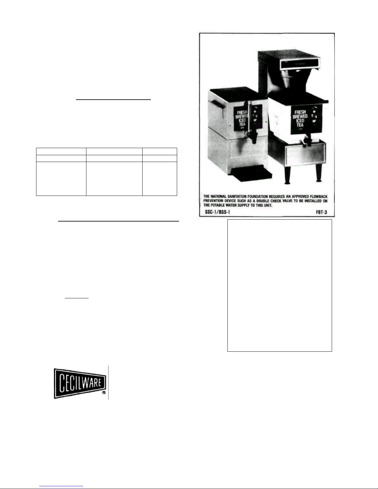
Specifications Dimensions Shipping Wt.
Model No. D x W x H (Ibs.)
FBT3 (Plastic)*
FBT3SS (Stainless)*
SSC-1 (Stainless)
BSS-1 (Stainless Base)
T1F (Plastic)
22" x 9 1/2 x 26 ½”
25 ½” x 13" x 27"
15 ½” x 11 ½” x 18"
15 ½” x 1 ½” x 18"
9" x 12 ½” x 16"
32
34
13
10
6 1/2
*Water Connection = ¼” Flare Fitting
Capacity: 3 gallons
Electrical: 120V, 1500W, 12.5 Amps, Line Cord Connected.
CECILWARE CORPORATION
43-05 20th Avenue, Long Island City, NY 11105-1295 • 718-932-1414
FAX 718-932-7860
531 Southern Boulevard, West Palm Beach, FL 33405 • 561-655-9696
FAX 561-655-8608
15549 4/94
INSTALLATION AND OPERATING INSTRUCTIONS:
1. Carefully remove brewer from carton.
2. Remove plastic urn and empty contents.
3. Install (4) 4" legs to bottom of unit.
4. Install brass inlet fitting to water valve.
5. Set unit into position and connect water line.
6. Turn water on - check for leaks.
7. Insure heater switch, located at the upper right rear of unit is in "OFF"
position.
8. Plug unit into 110-120 volt grounded outlet fused at 15 AMPS.
9. Assemble faucet to plastic urn as per enclosed instructions, replace urn with
cover making sure it is in its proper position.
10. Check to make sure brew basket is in position.
11. Depress "RED" power switch.
RED LIGHT in switch should now be on.
12. IMPORTANT!
During the hot water tank filling operation water will flow from the dilution tube
assembly. Therefore it is extremely important that the urn is in place in order to
provide a basin for this water.
To fill hot water tank proceed as follows:
A. Depress "RED" power switch - Red Light in switch should now
be on.
B. Depress "GREEN" brew switch and allow "FRESH - T" unit to
complete one cycle.
WARRANTY
Every Cecilware product has been carefully inspected before shipment. The finest of materials
and the highest standards of workmanship have
been built in to the equipment.
Within 1 year of purchase, should any Cecilware
product show defect in factory workmanship or
material, we agree to repair, at our option or replace
without cost to user such parts which prove upon
factory inspection to have been so defective. All
equipment must be shipped transportation charges
prepaid for acceptance. This warranty covers
replacement parts only, labor charges are covered
for 90 days after installation.
This warranty does not apply under the following
conditions:
• neglect or abuse of equipment
• excessive lime condition
• improper installation
• any outside modification to equipment
Every Cecilware urn body is covered for three
years. This warranty covers the stainless steel body
and stainless steel liners only.
Portable equipment such as Electric Fryers, Food
Warmers, Electric Stoves, Dispensers, Plug-In
Urns. Coffee Brewers and Warmers must be
returned to the factory or brought to an authorized
service station for repair.
Page 2
INSTALLATION AMD OPERATING INSTRUCTIONS (continued):
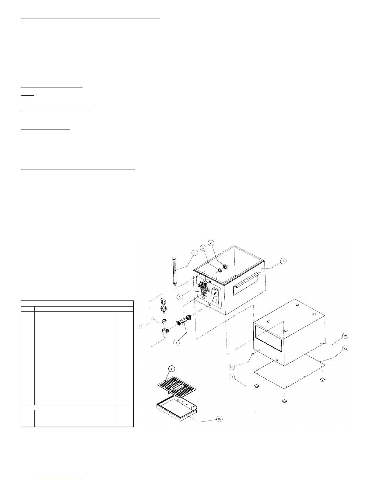
PARTS LIST
FIG.# DESCRIPTION
PART #
1
CARRIER ASSEMBLY (SSC
-1)
97243
Se
e Exploded View top:
C. Empty urn of water accumulated during first cycle.
D. Depress "Green" Brew switch once again. Near the end of this cycle water should flow from brew funnel, when this happens depress "RED" Power switch to
terminate cycle.
13. Locate heater switch at upper right rear of unit and switch to the "UP" or "ON" position. Allow 15 minutes for water to heat before proceeding.
14. Empty water from urn which may have accumulated during tank filling.
15. A. If using 3 gallon tea bags simply remove brew funnel and place bag inside (no wire basket is necessary if using Tea bag).
B. If using ground Tea Leaves make sure that wire basket is in place in the brew funnel. Place one paper filter into wire basket Add tea and replace brew funnel.
16. WITH "RED" POWER SWITCH ON, DEPRESS "GREEN" Brew switch and allow 10 to 12 minutes to complete brew time. Make sure funnel drip-out is completed
before removing brew funnel.
17. As required dispense tea from urn faucet into tea glass with ice.
CLEANING INSTRUCTIONS:
Daily: 1. Wipe exterior of dispenser with a soft damp cloth.
2. Wash tea reservoir with mild soap and warm water. Rinse thoroughly and replace on stand.
TEA BREWER ADJUSTMENTS:
The Tea Brewer has been factory set to brew 3 Gallons of tea. Should it become necessary to readjust or adjust for amounts less than 3 Gallons follow these steps
below,
TIMER ADJUSTMENT:
1. Unplug unit.
2. Remove 3 Phillips screws securing top panel
3. Lift off top cover exposing timer
4. To Brew more tea turn timer knob clockwise, to brew less tea turn timer knob counterclockwise,
5. Plug unit in and cycle unit. Repeat adjustment as necessary until desired volume is attained.
BREW VOLUME ADJUSTMENT (Adjuster Assembly):
1. Follow steps 1 - 3 in timer adjustment procedure.
2. Locate Brew Volume adjustment screw on clear block in front of tank top. (30)
3. With Brew Funnel out of unit, but with um in place, plug unit in and Depress Brew Switch. CAUTION: HOT WATER MAY SPATTER
AT THE BEGINNING OF CYCLE!
4. ADJUST FLOW FROM SPRAY HEAD BY TURNING VOLUME ADJUSTMENT SCREW CLOCKWISE TO REDUCE FLOW AND
COUNTER-CLOCKWISE TO INCREASE FLOW. AT PROPER ADJUSTMENT SPRAY PATTERN WILL FALL APPROXIMATELY 2
INCHES FROM TOP INSIDE OF URN WALLS.
5. PLUG UNIT IN.
6. REPLACE BREW FUNNEL, EMPTY URN AND PUSH BREW SWITCH. THE BREW VOLUME ADJUSTMENT IS CORRECT WHEN,
AT THE END OF THE BREW CYCLE DILUTION STREAM STOPS.
THE BREW FUNNEL HAS FILLED TO WITHIN 1" FROM THE TOP. BE CAREFUL NOT TO OVERFILL BREW FUNNEL.
2 NUT-FAUCET K105F
3 WASHER-FAUCET SHANK 07229
4 SIGHT GLASS ASSEMBLY 80245
5 DECAL 15546
6 FAUCET 80244
7 SEAT CUP 80222
8 FAUCET SHANK FOR SIGHT GLASS 92189
ASSEMBLY
8A FAUCET SHANK W/0 SIGHT GLASS 92192
9 CUP REST 75015
10 DRIP TRAY 75060
11 FEET 10059
12 STUD-DRIPTRAY 97007
13 BASE COVER 40990
14 STAND ASSEMBLY(BSS-I) 97242
15 FAUCET GUARD
5 DROP TUBE
9 TANK LID 86020
16 "0" RING
73368
DISC.
20014
2
Page 3

PARTS LIST
Fig # DESCRIPTION PART# Fig # DESCRIPTION PART#
1 TOPCOVER 40941 36 CLAMP IDEAL 34033
2 WIRE BASKET (OPTIONAL) 75057 37 ADJUSTOR BRACKET 97219
3 BREW FUNNEL ONLY 97504 38 HOLD DOWN BRACKET 73317
4 RESTRICTOR/SCREEN ASSY 38325 39 HOSE CLAMP 34025
5 DROPTUBE DISC. 40 TEE EXPANSION ASSY 97221
6 RESTRICTOR ASSY NUT 03045 41 SILICONE TUBE 6'/2" 77278
7 HANDLE 02016 42 SILICONE TUBE 9" 77246
8 BREW FUNNEL NUT 03069 43 TEE 10054
9 TANKLID 86020 44 SILICONE TUBE 6y2" 77244
10 URN TANK 86011 45 SILICONE TUBE 9" 77246
11 DECAL-FRESHBREWED TEA 15546 46 HOSEBARBELBOW 09295
12 DECAL-FILL LINE LEVEL 15551 47 THERMOSTAT BRACKET 73276
13 FAUCET 80218 48 THERMOSTAT 59016
49 SPACER 38265
14 WASHER 19015
50 TERMINAL BLOCK 60105
15 NUT-FAUCET 03047
51 INLET HOSE FITTING 95101
16 "0"RING 20014
52 TINNERMAN NUT P228F
17 DISHWASHER LABEL 15552
53 WATER VALVE 80235
18 ACCESS PANEL 40934
54 TANK DRAIN VALVE 80224
19 SPRAY HEAD 09296
55 HEATING ELEMENT 87037
20 SPRAY HEAD NUT K107F
56 LOWER REAR PANEL 40916
21 DILUTION TUBE ASSY 97216 57 TINNERMAN NUT 03011
22 POWER SWITCH 56046 58 REAR CENTER PANEL 40918
23 DECAL-SWITCH 15547 59 HIGH TEMPERATURE CONTROL 59010
24 BREW SWITCH 56047 60 TANK Q7119
25 TIMER L265F 61 TANK BAFFLE 97215
26 TUBE TANK/SPRAY HEAD 77243 62 GASKET SEAL 20039
27 GROMMET M090F 63 TANK TOP 97214
28 SPRAY HEAD FITTING ASSY 95138 64 TANK CLAMP 97131
29 WASHER M197F 65 TANK CLAMP NUT 03053
30 ADJUSTOR ASSY 99603 66 TANKCLAMP BOLT 06121
31 STRAIN RELIEF 57032 67 REAR TOP COVER 40938
32 POWER CORD C032F 68 DECAL HEATER ON-OFF 15589
33 4" PLASTIC LEG (SET OF 4) M172F 69 HEATER SWITCH L069F
34 NUT RETAINER 03068 70 BREW FUNNEL ASS'Y 95501
35
TUBING SILICON 21 ½”
77273
70A PLASTIC BREW FUNNEL
95172
3
Page 4

TROUBLE SHOOTING GUIDE
•
For Qualified Service Persons Only
Warning: Unplug the dispenser power cord before repairing or replacing any internal components of units.
Trouble Probable Cause Remedy Trouble Probable Cause Remedy
No Water
A) Dispenser Unplu
gged A) Plug Unit In
D) Inoperative High Limit
E) Loose Electrical
Connection
D) Replace High Limit
E) Check All Electrical
Connections for Contact
When Brew
Switch is
Depressed
B) Circuit Breaker Off or
Tripped
C) Power Switch Off
D) Inoperative Dispense
B) Reset Breaker
C) Depress "RED" Power
Switch
D) Replace Switch
Tea Too Weak A) Too Much Water (IN A) Turn Timer Counter
Switch
EXCESS OF THREE
Clockwise and Re
-
Brew
E) Inoperative Timer
E) Replace Timer
GALLONS)
Repea
t until desired
F) Hot Water Tank Not
F) Refer To Tank Filling
Strength is achieved
Full
Instructions
B) Adjuster Assembly out
B) Refer to Adjuster
G) Water Supply Off
G) Turn On Water
of Adjustment
Assembly instructions
H) Inlet Screen Plugged
H) Remove Screen
&
Clean
C) Brew Water Not Hot
C) Turn Up Thermostat
I)
Inoperative Inlet Water
I) Replace Water Valve
Enough
Valve
D) Spray Head Limed Up
D) Remove Spray Head
J) Loose Electrical
J) Check all
Electrical
and Delime. When Re
-
Connection
Connections for contact
placing Spray Head
Tighten only Finger Tight
Water Does
Not Shut Off
A) Leaking Inlet Water
Valve
A) Replace Valve
Tea Too A) Not Enough Water A) Turn Timer Knob Clock
B) Brew Switch Stuck B) Replace Switch Strong (LESS THAN 3 wise and Rebrew,
C) Faulty Timer
C) Replace Timer
GALLONS)
Repeat until Desired
Strength is Achieved
Water Leaks
From Tank
A) Dilution Tube Blocked or
Limed Up
A) Remove
Tube and Check for
Blockage
Water Boils
A) Malfunctioning
A) Replace Thermostat
Vent Tube B) Vacuum Tee Plugged B) Remove Tee and Check
Thermostat
for Blockage
B) Thermostat Not B) Tighten Retaining Nuts
Contacting Tank
Water From
Spray Head
Not Hot
A)Heater Switch In "Off"
Position
B) Inoperative Thermostat
A)Turn On Switch
B) Replace Thermostat
Water Spills Over
Top of
A) Adjuster Assy. Set Too
High
A) Refer To Adjuster
Assembly Instructions
C) Inoperative Heating C) Replace Heating Brew Funnel B) Brew Funnel Clogged B) Remove Restrictor,
Element
Element
Screen Assy and Clean
4
 Loading...