

Page 1
Century Series
Air Pot Brewers
Page 2
Century Series Air Pot Brewers
SPECIFICATIONS AND OPERATION MANUAL
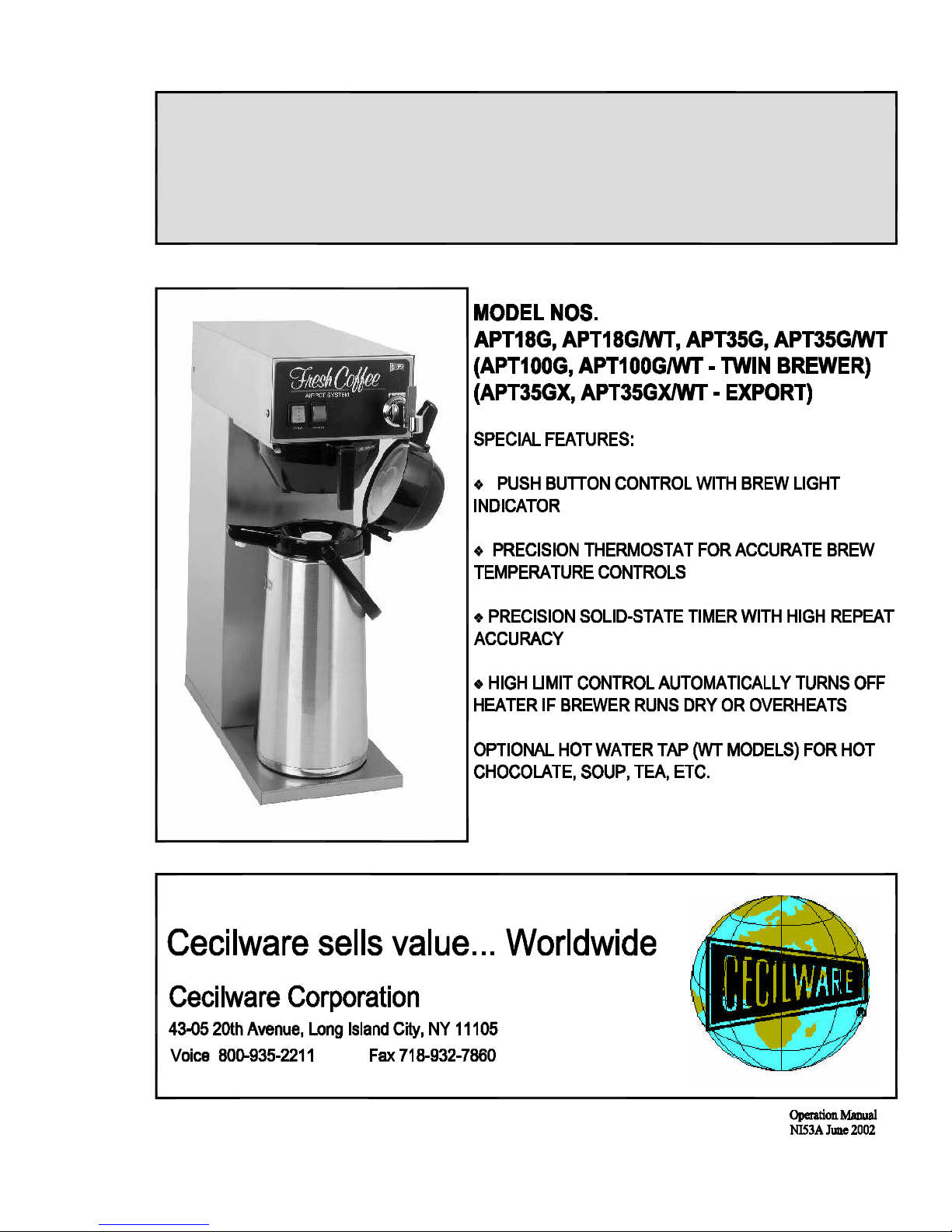
Model Nos.
APT18G, APT18G/WT, APT35G, APT35G/WT
(APT100G, APT100G/WT – TWIN BREWER)
(APT35GX, APT35GX/WT - EXPORT)
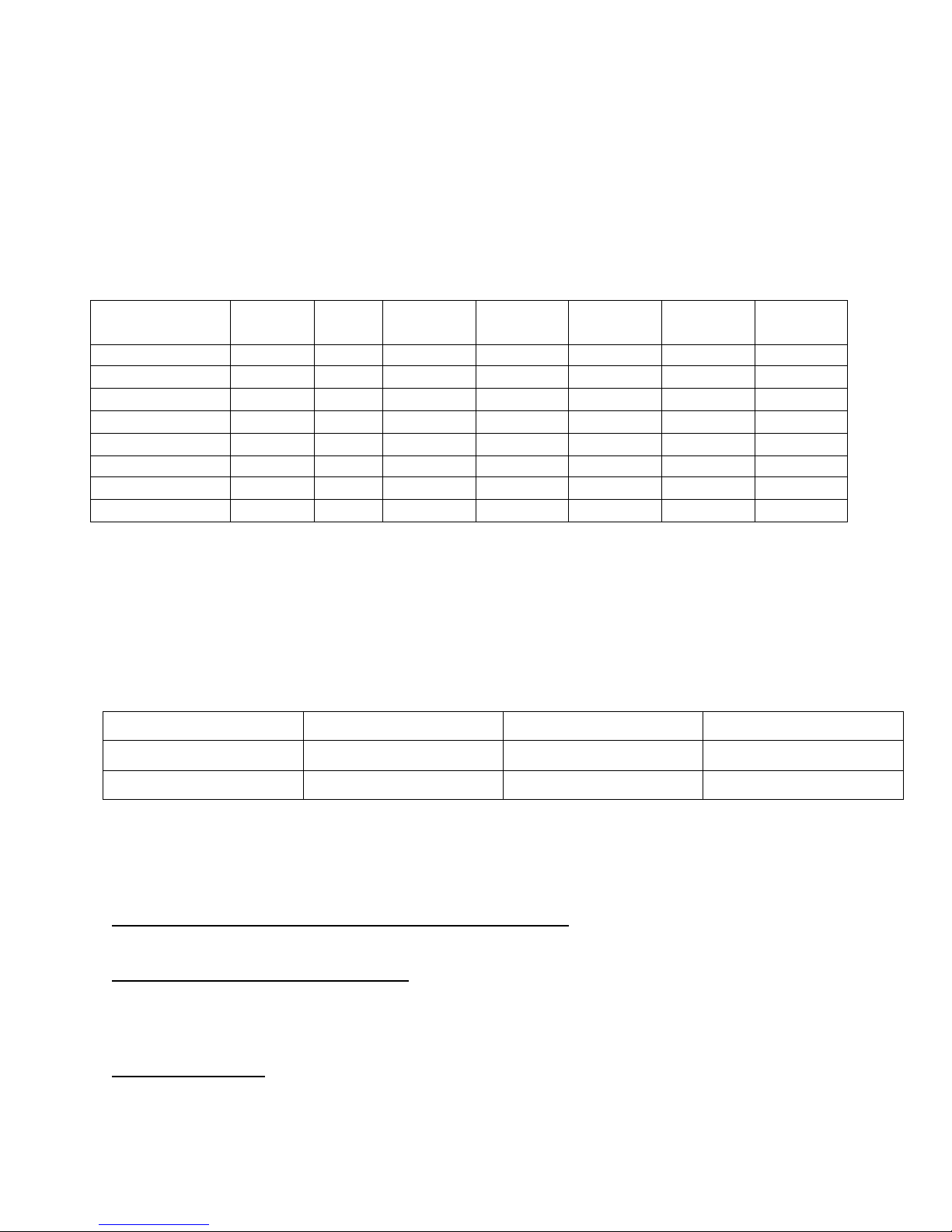
Electrical Specifications:
Model No. Volts Phase Hz. Watts Amps Receptacle
Nema No.
APT18G 120 1 50/60 1.8 Kw 15 5-15R 15
APT18G/WT 120 1 50/60 1.8 Kw 15 5-15R 15
APT35G 240 1 50/60 3.5 Kw 20 6-20R 20
APT35G/WT 240 1 50/60 3.5 Kw 20 6-20R 20
APT35GX 220 1 50/60 2.4 Kw 11 ---- 15
APT35GX/WT 220 1 50/60 2.4 Kw 11 ---- 15
APT100G 120/240 1 50/60 6.4 Kw 27 L14-30R 30
APT100G/WT 120/240 1 50/60 6.4Kw 27 L14-30R 30
Line cord included. “X” models for export.
NOTES: APT100 Model includes twist lock plug wired for 4 wire 120/240V including Neutral and
Ground.
(120V Models – available on special order and requires a 15amp circuit breaker.)
Water Connections: ¼” flared water inlet fitting and flare nuts for ¼” o.d. copper tubing with a
minimum water pressure of 20 p.s.i.
Circuit
Breaker
MODEL Width Inches (cm.) Depth Inches (cm.) Height Inches (cm.)
APT18/35 8 (20.3) 18 (45.7) 25 1/4 (64.1)
APT100 17 (43.2) 18 (45.7) 25 1/4 (64.1)
INSTALLATION AND START-UP INSTRUCTIONS
FOR AIR POT BREWER
Not Included with this Brewer unless ordered separately
2.2 liter Air Pot, Part No. V223A
Things to note when Brewing Coffee
• This brewer is set for 2.2 liter capacity Air Pot.
• Volume can be easily be adjusted for 1.9 liter or 2.5 liter Air Pots.
WATER HOOK-UP (Check Local Plumbing Codes)
The National Sanitation Foundation (NSF®) requires the following for an NSF approved hook-up:
1. A quick disconnect water connection or enough extra coiled tubing (at least 2x the depth of the unit)
so that it can be moved to clean underneath.
2. An approved back flow prevention device, such as a double check valve, must installed between
brewer and water supply.
Ni53a.doc Page 1 of 4
Page 3

Water Connection:
APT Brewers are supplied with 1/4” flared water inlet fittings and flare nuts.
Use a 1/4” diameter copper tubing to connect brewer to a cold water supply line with a minimum water
pressure of 20 p.s.i.
HIGHLY RECOMMENDED: An external water supply shut-off valve near the brewer and a water purifier filter for
better tasting fresh brewed tea and coffee beverage.
Electrical Connection:
APT18 - 120 volt, 1.8 kw - Brewers require a single use (dedicated) 15 amp grounded receptacle.
APT35 - 240 volt, 3.5 kw - Brewers require a single use (dedicated) 20 amp grounded receptacle.
APT100 – 120/240 volt, 6.4 kw - Brewers require a single use (dedicated) 30 amp twist lock
grounded receptacle.
TANK PRIMING PROCEDURES
THESE INSTRUCTIONS ARE FOR INITIAL PRIMING ONLY AND DO NOT HAVE TO BE
REPEATED FOR NORMAL OPERATION.
NOTE: The Heater toggle switch, located in back of unit, or under the top cover, must be in the
OFF POSITION.
1. Remove sample filter pack from brew funnel and insert brew funnel back into machine.
2. Place an empty Air Pot directly under brew funnel.
3. Plug the power cord into a proper receptacle.
4. Activate the RED Power Switch. The tank will start filling automatically. Allow approximately 4-5 minutes
for the tank to fill.
5. After the water tank is filled, activate the Heater Switch ON POSITION. Allow approximately 15-20
minutes for the water to reach a brew temperature (197°F). The heat up time will depend on the water inlet
temperature, the input voltage and the wattage of the elements in the machine.
When the (Green) Ready Light comes on the machine is ready to start brewing.
6. Press Brew Button:
BREWING INSTRUCTIONS FOR COFFEE
1. Place a paper filter into brew funnel and add 2.5 oz. of fresh ground coffee into the filter. Place the funnel back
into brew head of machine.
2. Unlock the Air Pot Cover and remove the Pump Assembly from the Air Pot.
3. Place the Air Pot with cover open on the support shelf under the funnel.
4. When the Green READY light inside the Brew Switch comes on, depress the Brew Switch.
Note: Allow 5 to 6 minutes for the complete brew cycle. DO NOT remove funnel from the brewer until it
has completely stopped dripping
6. Remove AIR POT from the brewer, insert the air pump tube, and snap the top closed.
7. Serve fresh brewed coffee from dispenser nozzle by pushing down the round large button on top of the cover.
ADJUSTMENTS:
Timer Adjustments (To adjust total volume of COFFEE)
1. Turn the Power Switch to OFF and remove the top cover.
2. Locate BREW TIMER and adjust as follows:
A. For MORE volume, turn TIMER KNOB CLOCKWISE.
B. For LESS volume, turn TIMER KNOB COUNTERCLOCKWISE.
C. Go through a complete brew cycle and repeat adjustments if necessary.
CAUTION: Turn TIMER KNOB only in SMALL increments at a time.
Ni53a.doc Page 2 of 4
Page 4

Thermostat Adjustments
Thermostat is factory set for proper operating temperature of 197°F to 203°F with the adjustment Knob set to the
maximum clockwise position. If field adjustments are needed proceed as follows:
To DECREASE temperature, turn the control shaft slightly to the left COUNTERCLOCKWISE.
To INCREASE temperature, proceed as follows: With the control knob ALREADY TURNED TO ITS MAXIMUM
CLOCKWISE POSITION, locate the small, slotted ADJUSTMENT SCREW inside the hollow shaft. By using a
narrow blade screwdriver engage the slotted adjustment screw and turn it an 1/8 of a turn slowly to
the left (counterclockwise) until a click is heard and the Green Ready Light goes OFF.
NOTE: Measure the water temperature at the head with the spray head removed in order to capture a solid
stream of hot water. DO NOT forget to REPLACE spray head afterwards.
In HIGH ALTITUDE locations, (5000 ft. above sea level) the thermostat setting will have to be lowered to
prevent boiling.
MAINTENANCE TIPS.
1. Remove and clean spray head at least once a week. In hard water areas, inspect and clean every other day.
2. If excessive build up of lime is present, de-lime or replace the heating tank.
CLEANING INSTRUCTIONS
Use a mild dishwashing detergent to clean the STAINLESS STEEL, PLASTIC BREW FUNNELS and AIR POTS.
Rinse thoroughly. Clean and Polish the outer surfaces of the STAINLESS STEEL AIR POTS and BREWER with a
STAINLESS STEEL CLEANER & POLISH such as the 3M™ Stainless Steel Cleaner & Polish, which is U.S.D.A.
approved.
TROUBLESHOOTING GUIDE.
Brewing Problems.
Weak Coffee
1. Low water Temperature -------------- Adjust thermostat, should be between 197°F - 203°F
2. Spray Head clogged ------------------- Remove and clean weekly or as needed
3. Too Coarse Coffee Grind ------------ Should be Drip Grind type
4. Not enough Coffee -------------------- Use a minimum of 2 oz. Of coffee
No water from Spray head when brew switch is depressed.
Note: Allow 30 seconds for time delay.
1. Power Switch is off or unit is unplugged.
2. Water Supply is off
3. Hot Water Tank is not full
4. Defective water inlet valve or dispense valve
5. Defective brew switch
6. Defective timer
7. Inlet filter Clogged
Water from spray head not hot.
1. Heater switch is off
2. Thermostat is off or defective.
3. High limit switch has tripped and does not reset – replace high limit switch
3. Tank heater is defective
Ni53a.doc Page 3 of 4
Page 5

5 6 7 8 9
10
11
4
3
2
1
24
23
22
12
CECILWARE
13
14
1718192021
16
25
15
PARTS LIST
ITEM
Ni53a.doc Page 4 of 4
DESCRIPTION
SPRAY TUBE ASSEMBLY
1
TIMER HOT WATER DISPENSER (120v)
2
TIMER HOT WATER DISPENSER (240V)
2
THERMOSTAT
3
THERMOSTAT KNOB
4
WATER LEVEL CONTROL (120V)
5
WATER LEVEL CONTROL (240V)
5
WATER LEVEL SENSOR
6
SILICONE GASKET
7
SCREW 1/4-20 x 5/8 S.S.
8
TANK TOP ASSEMBLY
9
WATER TANK SUB-ASSEMBLY
10
HEATER ELEMENT 1750W (120V)
11
HEATER ELEMENT 3500W (240V)
11
HEATER ELEMENT 2400W (220V) EXPORT
11
PART NO
K642Q
L592A
L593A
L532L
M008A
L566A
L599A
K402Q
M600A
P465A
RV34Q
RV33Q
G382A
G358A
G357A
HI-LIMIT
12 L573A
ELBOW 90°
13 K525A
SILICONE TUBING 1/2" I.D. x 14" LONG
14
15
TUBING 1/4" COLD WATER INLET H328Q
MT. BKT, WATER INLET VALVE
16
17
HOSE NUT FITTING
VALVE, WATER INLET (.35GPM) (120V)
18
VALVE, WATER INLET (.35GPM) (240V) L594A
18
FAUCET ASSEMBLY
19
SPRAY HEAD ADAPTER
20
SPRAY HEAD
21
DISPENSE VALVE (120V)
22
DISPENSE VALVE (240V)
22
SILICONE SEAL, 12mm (0.466 I.D.)
23
NOZZLE
24 K629A
CONTACTOR25 B177A
M611A
RQ52A
K491A
L588A
D085A
K107A
E004A
L596A
L598A
M461A
Page 6

Page 7

DISPENSE
VALVE
DISPENSE
VALVE
WATER INLET VALVE
WATER LEVEL
PROBES
HI-LIMIT THERMOSTAT HEATER SW
TERMINAL BLOCK
L2 N L1
LEVEL
CONTROL
CECILWARE CORPORATION
ELECTRICAL DIAGRAM, APT100G, APT100G/WT
 Loading...