

Page 1
PROGRAMMABLE
SEQUENTIAL 2 outputs
I-210
TECHNICAL CHARACTERISTICS
Voltage. ........................................ 12 V.C.C.
Low energy. ................................ . 30 mA.
Maximum consumption. ................ 1125 mA.
Maximum load per output. ............. 5 A.
Number of outputs. ........................ 2
Number of programs per output............ 1
Max. Program. ............................................... 120 steps.
Selectable step Times. ........................ 0.5 sec. to 99 min. 59 sec.
Confirmation number of tickets or Paro. ........... 1 per output.
PC board measures. ....................................... 109 x 75 x 30 mm.
PC Board Visualization and Control. ....... 131 x 52 mm.
Module measures. ............................................ 131 x 90 x 52 mm
The I-210 is a PLC with 2 outlets. Each output can contain up to 120 program steps.
The steps can be configured with three states: output connected ',' exit off "and" exit as entry level. " The time step is
selectable from 0.5 sec. and 100 minutes.
Using the keyboard that incorporates a simple interface and viewable through the LCD of the circuit, the module will allow the
grouping and configuration steps outlined in chart form, the pattern of desired operation for each output.
Keeps in memory the programs carried out, even after power off.
Includes display relay status, LED connection indicators and terminals for wiring.
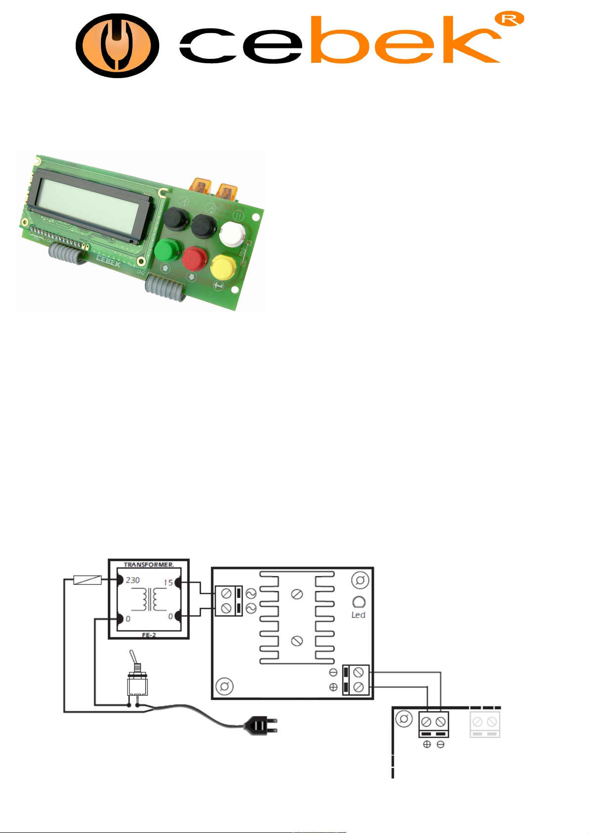
POWER SUPPLY. The I-210 must be supplied with a voltage of 12 V. S.C. Adequately stabilized, so we suggest not using
simple power supply, adversely affecting circuit operation, but a power supply. We recommend the EF-2, which is well suited
to the needs of the module.
Install a fuse and a switch. Both are essential to protect the module for your own safety, as reflected in the CE standard.
Do not use the same power of I-210 to power other devices generating industrial parasites, such as relays, motors, coils, etc.
Queried the provision of the outputs of the source, positive and negative power to the input terminals indicated in the drawing.
Then, verify that installation was successful.
Fuse
250 mA
Switch
FE-2
www.cebek.com - [email protected]
I-210
Page 2
I-210
PROGRAMMING The I-210 is a PLC, a module which you can set a full schedule operation for each output. The circuit
also thanks to its programming step by step, we will set up a flexible graphical performance. They usually present needs
work on different devices, on which asynchronous operation is required and complex. Hard work applicable patterns with
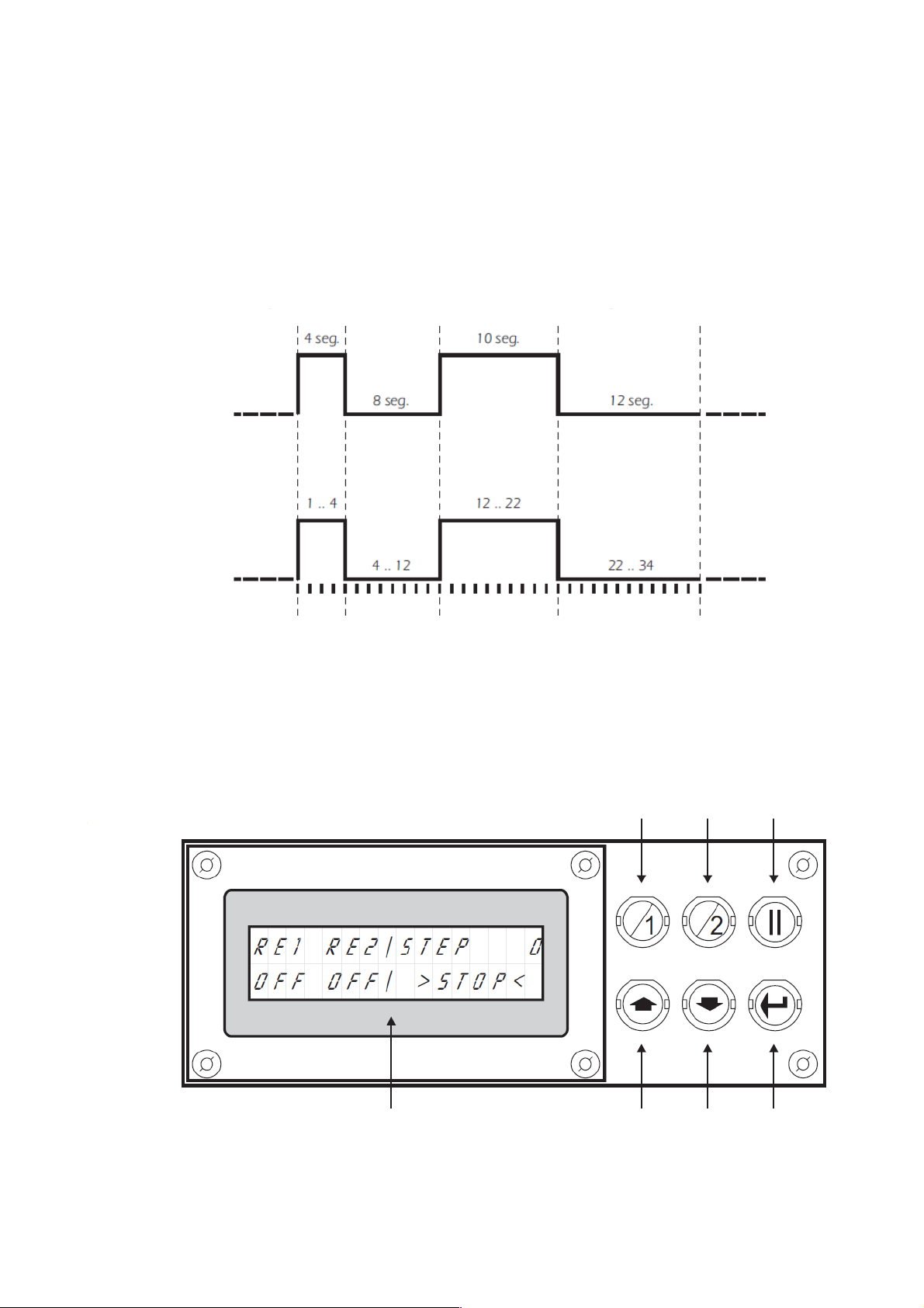
simple timers. These devices typically require such cycles capricious eg, 4 sec. connection, immediately after 8 sec. off,
after which 7 sec. of connection, then again 12 sec. disconnect, etc. These "Guidelines for Operation" can be easily
programmed through the I-210. The module, however, instead of having a standard measure by which to make the graph,
for example, sec., as ilustrábamos above, the circuit employs "steps", this being its smallest measure. Describe later how
to assign a measure of real time to the division step. The graph is made by grouping steps. Returning to the example
above, the circuit should be scheduled first grouping step 0 to 4, which will be configured "connection" in step 4 to 12 in
the "disengagement" from 12 to 22 in "connection", and finally from 22 to 34 in disconnection. Finally, assigned as a
measure of time per step, 1 sec. See Fig. 1
Figure 1 - Sample performance graph
Common Graphic
Graph in step
Sequence 1
Sequence 2
Sequence 3 Sequence 4
Programming the I-210 is similar to that used in home videos. Using the buttons and display panel embodying the control
module will perform all functions. See Fig 2. Power feeding module. The display will briefly describe the module, and
following her visualize the data shown in Fig. 2.
Figure 2 - Front view of the control lever of I-210.
Key relay 1
Key relay 2
Pause key
Working screen
Display screen
2
www.cebek.com - [email protected]
Up key
Key Down
Among key
Page 3
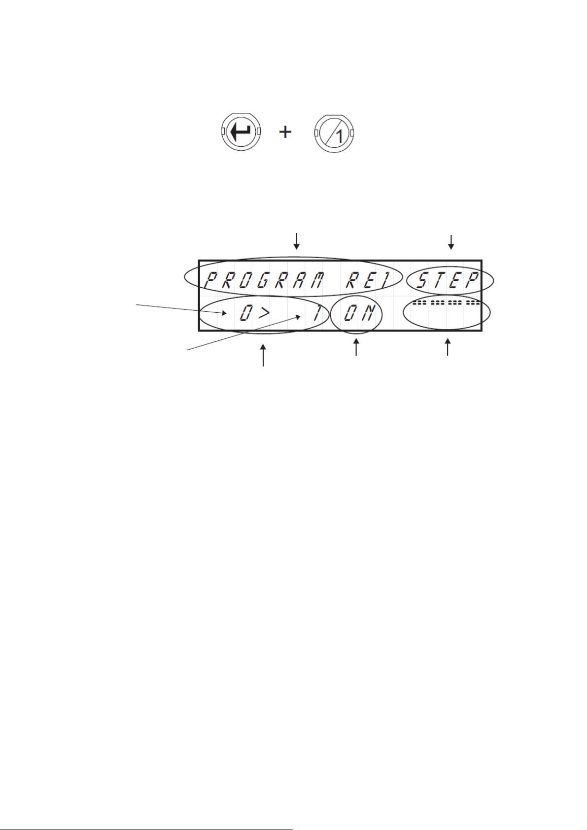
Each output, consisting of a relay, has a separate program with a maximum capacity of 120 steps. To enter the program
each output from the job screen, press the Enter key and while pressing it, then press the button on the relay (output),
which want to access. See Fig. 3
Figure 3 - Example of access to
the program relay 1
The display shows the indicator relay program and the sequence indicator, the indicator of steps, the status indicator
output and graphics performance. See Fig. 4.
Figure 4 - Description of the screen "programming"
I-210
Program Indicator
Step sequence starting
The final step sequential
Exit Status
Step indicator
Sequential Indicator
Performance indicator
graphs
To facilitate understanding of the programming of I-210, illustrate the description of this, the graphical programming operation
of FIG. 1. Please follow the instructions indicated below.
Press the Enter key and relay 1 "to enter the program relay. By accessing the programming screen the cursor is placed in the
display of steps. The indicator will always show steps to the left of the symbol ">" the initial step after which the order will begin
on the start, and right, the final step where this will end, making a "Sequence."
For each click on the "Up" and "Down" may increase or decrease the final step in the sequence. If you hold these keys increase
or decrease will take place faster.
Now press the "Up" until the final step sequence is equal to 4.
Then you must tell the module as you want to act out during that sequence. The module supports three possible output states:
ON, OFF, and EX, included in the indicator of "State of Exit." If you select ON, during the sequence, the output is connected, if
you select OFF, the output on the other hand, remain disconnected. If you select EX, the output function on
input state of "Confirmation or stop" question. This output mode is detailed in "Confirmation Check or Stop."
To move the cursor to the "State of Exit", press "Pause." Each press on this key cyclically rotate the location of the cursor
between indicators of Sequence, Step and output status.
Stand on the indicator of state of the output. Using the Up and Down keys to select one of the three output state. Select the ON
state.
After composing the sequence, and assign an output state, the module will indicate if this is the last, being the end of the
program, or if you want to link to the next. To perform this operation must be in the Sequence Indicator. Press the Pause button
to stand on it.
By default, the circuit will always display the word "STEP". If you press the Up or Down will rotate among the four possible
functions of Sequence Indicator: Step, End, End * and Del.
The "Del", is described in paragraph Delete Program.
End option, completes and records in memory the program.
End * The option performs the same function End, but making the cyclic program. Thus, in the normal operation of the circuit,
when it reaches the last step etching, the module will restart the program continuously, or by default until you remove the
program.
Step option, record the sequence performed, and link to the next, allowing the configuration of a new program continuity.
Press the Up or Down until the display shows the option Sequence Step. Then press the Enter key.
Next, the steps change indicator, showing the final step in the above sequence to the left of the symbol ">" and the first of the
new right.
If changing sequence, an output change, the performance graph will reflect it.
Press the Up key until the final step remains at 12. Then press the Pause key to select the output indicator. As default, the new
footage shows off the form provided and in this case coincides with the state that we want to assign to the output, not make any
changes on it, press the Pause key.
The cursor will change to the sequence indicator. Step select the option, and press the Enter key to record the sequence made
and start a new one.
www.cebek.com - [email protected]
3
Page 4
I-210
The display will show the steps "12> 13." Change the final step up to 22, (use the Up key). Then navigate to the "State of
Exit" (Pause button) and change the status to On (Up Key). Then place the cursor in the "Sequence Indicator" (Pause
button) and press Enter. The sequence will be recorded and displayed the next module.
Now only will schedule the final sequence. Change the final step until it shows 34, assigned to the State Output Off, and
navigate to the sequence indicator. This time, because we want to end and not continue the program, instead of selecting
the Step option, choose the End. After pressing Enter, the program will be completed, recorded in memory, and the module
will return to the job.
Do not delete this program, we will use later to explain other features of the circuit.
Before starting a new program, we advise you always draw on paper, the graph of performance you want in the module, it
will prevent a large number of changes and corrections which will result in considerable savings of time.
When accessing the program on a relay which still had not recorded anything (without a signal "End"
or "End *"), you can not leave that screen until the place a Sequence Indicator "End", "End *" or "Del".
Note. The I-210 to adjust the contrast of the screen. To do this, adjust the potentiometer inserted in the circuit board.
ALLOCATION OF TIME BY STEP. As we indicated in the section Programming the module sets the program in
"steps", without using a measure of time.
Using the "Time By Step", the module will assign a specific time adjustable from a minimum of 0.5 sec. up to 99 minutes,
59 seconds., 9 / 10 sec., which will set the time equivalent of a "step."
Thus, if the equivalence situásemos pass in 1 sec., The program implemented earlier, would be a total time of 34 sec. If
situásemos, however, the "Time by Step" (the equivalent of step) in 1 minute, the above program would last a total of 34
minutes.
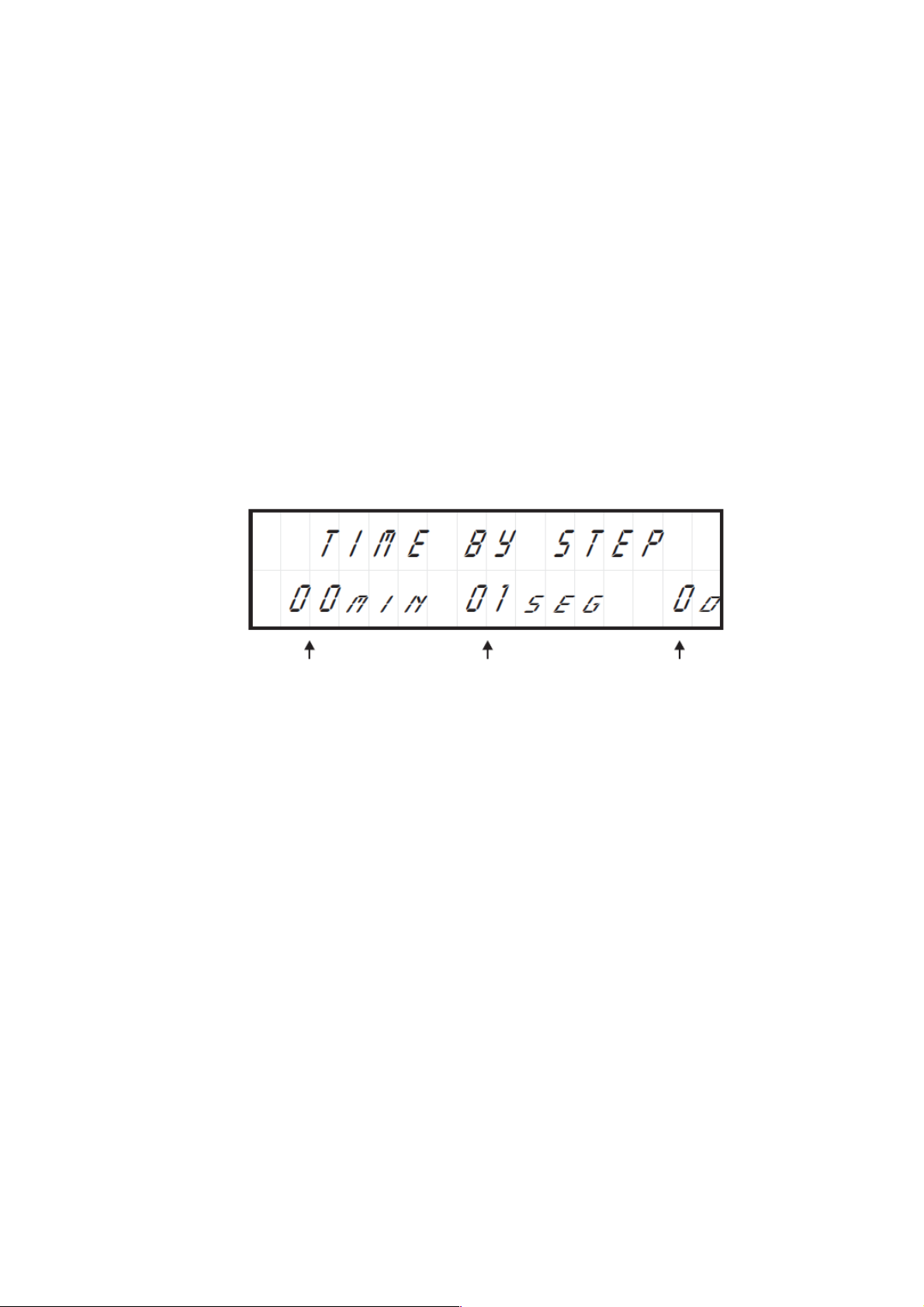
To enter the "Time by Step" from the job screen, press the Enter key, and while pressing it, press the Pause key. If done
correctly, the screen will display as shown in fig. 5.
Figure 5 - Screen "Time by step"
Minutes Seconds
By default, when you access the screen, the cursor is placed in the tenths of seconds. To move from the tenth to the second
or the minute cycle, press the Pause key. To change the value of any of them, use the Up or Down.
Once the change is made, press the Enter key and the module will record the new reference time, returning to the work
screen.
Remember that the minimum working time is 5 tenths. If you select a time below, but the display screen, the module will
automatically record the minimum allowed, 0.5 sec.
Moreover, time per step will be assigned as an equivalence set by step to all programs module
Erasing the program. The I-210 supports the complete erasure of a program. To do this you must first access the program
you want to delete (key Enter + No relay). Then, at any point in the program, go to the Sequence Indicator and select "From."
Then press the Enter key. Immediately afterwards, the module will completely erase the program, returning to the work
screen.
To delete only part of the program must make a modification. See Editing and Viewing Software.
Tenth of a second
DISPLAY AND PROGRAM MODIFICATION
CONSULTATION PROGRAM. For a program must first access it. Using the newly created program, from the job screen,
press the Enter + Relay 1 will access that program.
Then press on, or hold "Relay 1", you can see how the display shows step by step the content and course of the program until
its end. Press the "Relay 2" to go back.
Do not use the up or down to scroll through the program, the function of these is to increase or decrease the final step of
each sequence, modifying the program, not the Watch it, you should always be done with the keys Relay 1 and Relay 2.
MODIFICATION PROGRAM. When you scroll through the keys Relay 1 and Relay 2, may occur at the point of the
program you want. At that point, and using the Up or Down may modify the program, following the mode
regular programming.
Suppose that in the last sequence of the program (Step Off sequence 22 to 34), want to insert an "On" in step 26 to step 30.
27”, To do this, navigate using the keys relay 1 or relay 2 in the step indicated in the display as "26> 27", then, if I were not
standing on the steps Indicator, press up until the final step is 30. A
Then press the Pause button to move to the state of the output and switch to the ON state (Up or Down keys.) After this
operation, again using the Pause key change to the sequence indicator, check that indicates the STEP option and then press
Enter. The change will be made and can verify the changes by using the arrow Relay 1 and Relay 2.
4
www.cebek.com - [email protected]
Page 5
I-210
To exit the working screen, hold for 2 seconds. Pause key. If the program does not contain a signal "End"or "End *", you
must create one to get out. If the modification of a program a sequence that overlaps and exceeds by length of which
reflected the end of the program (signal "End" or "End * ") must indicate a new end of program.
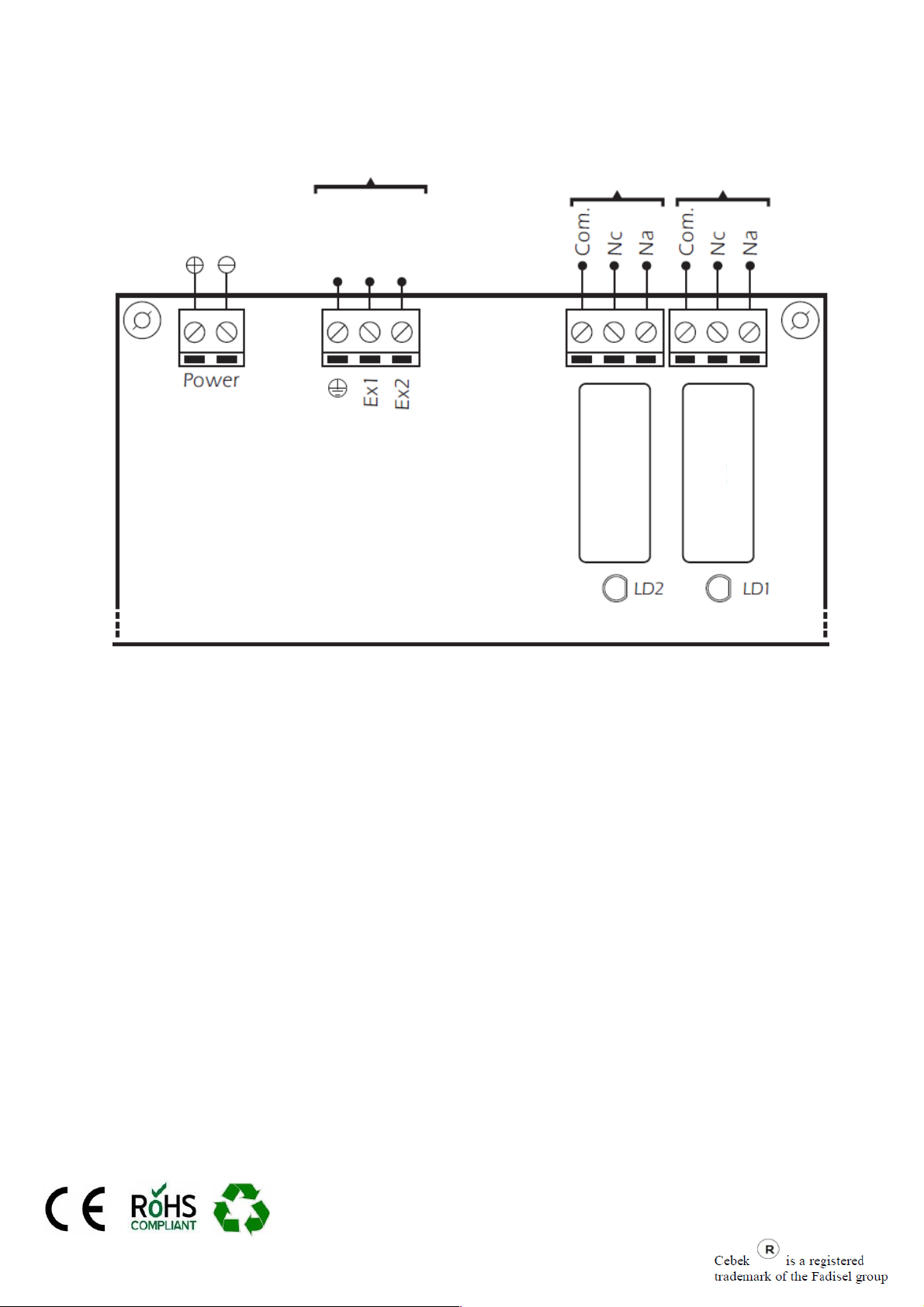
CONFIRMATION TICKETS OR STOP. The form I-210 incorporates an input "External"for each relay. Each of these
inputs act on the agenda of the corresponding relay. In those sequences where the state program's output was set to "Ex",
the module to reach them and as lasting, continual check the entry. If the input is in contact with the common, the relay will
connect, if on the contrary, the entrance was open, the relay is disconnected. Observe the General Wiring.
PERFORMANCE OF WORK. Working Screen (Fig. 1, p. 2), is the main module, this display shows the current status
at any time the status of each output, displaying under the names of each relay (RE1 or Re2), the exact mode of output,
On, Off, or Ex .
Keys either Relay 1 or Relay 2, when pressed activate all prerecorded programs, initiating the operation of the
module.
The Pause key, as its name suggests, will pause to freeze the program in the step that was pressed, restoring the system
to again be pressed.
Enter button, hold no combination with another key, will perform a program stop, "Stop", leaving the circuit waiting for a
new start.
RUNPauseStop<" onmouseout="this.style.backgroundColor='#fff'"Working Screen indicate at any time if the program is
running, if it is paused or if it is stopped, correspondingly displaying the following message:> RUN <""> Pause <"and">
Stop < ".
Likewise, the display will continuously step in which the program is showing the message "No STEP", where "No" will
counter the current step.
Note that not all programs have the same length or duration. Therefore, although the module will execute at the same
time, shorter, are off, pending the end of the major. This point should be especially taken into account, if any of the
software was cyclical, and then, after completion of the longest, and having concluded its function the remaining, only the
cyclic restarts, continuing his work indefinitely until making a "Stop".
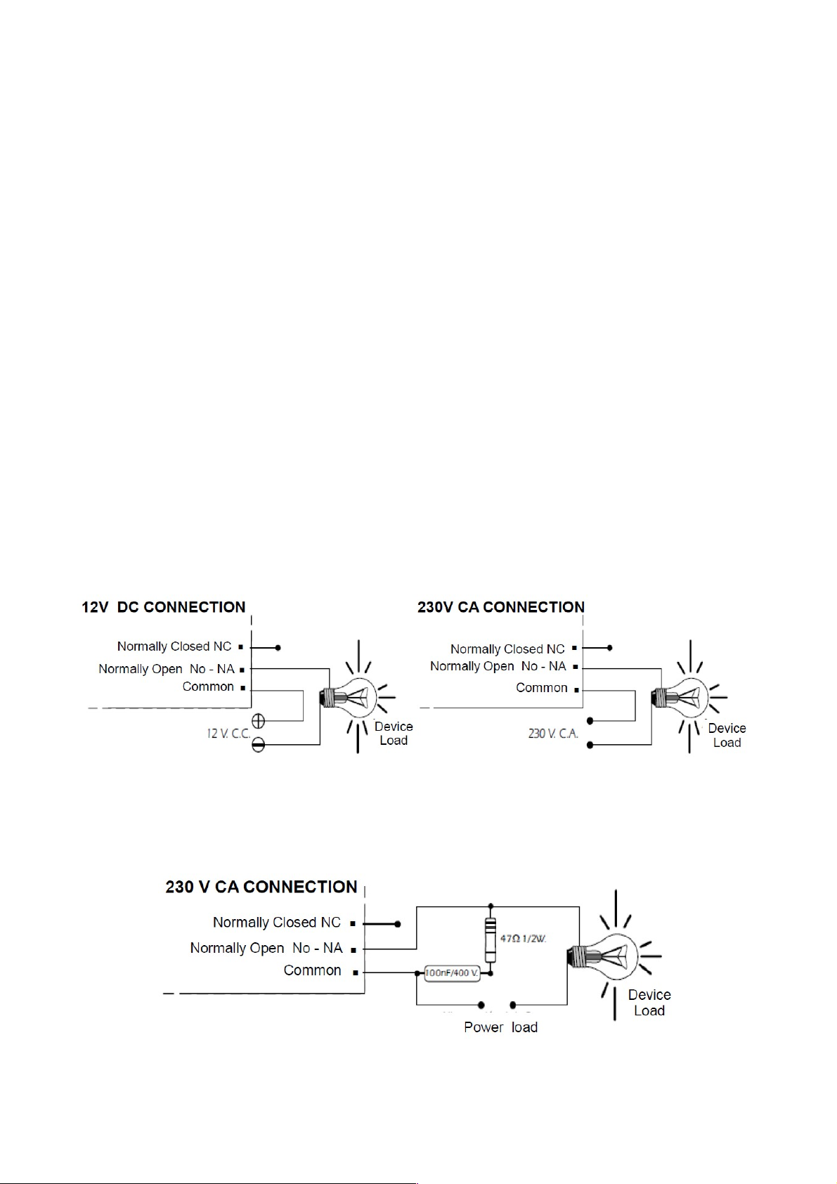
CONNECTION OF OUTLETS. LOAD. The outputs of the I-210 is performed by relays, devices that support any type
of load does not exceed 5 A. The relay has three output terminals. The rest normally open (NO), the Sleep normally closed
(NC) and the Joint Operation of this mechanism is identical to a switch whose two terminals NA and the common to the
inverse function must be used and common terminal CN is shown in Figure The typical connection for a device operated
at 12 V. S.C. and one operated at 230 V. C.A. See paragraph Connecting the charges.
ABOUT THE OUTPUT. During operation of the circuit, and according to its load, it could happen a fluctuation or an
incorrect output performance. If this happens, install a circuit sparking between the two relay contacts used in this connection,
as shown in the drawing.
www.cebek.com - [email protected]
5
Page 6
GENERAL WIRING MAP.
Entries confirmation
Output 2
I-210
Output 1
Entry
alimentation
n
o
m
m
o
C
I-210
1
2
t
t
u
u
p
p
n
n
I
I
1
2
y
a
l
e
R
y
a
l
e
R
www.cebek.com - [email protected]
 Loading...