

Page 1
ELECTRONIC
CIRCUITS
ENGLISH.
The DA-06 manages the balances stored in the chip card, providing an adjustable connection time by the
consumption of each one.
It operates in independent mode, being able to operate like cards recorder or balances controller. It
incorporates local controls for recording, activation, deny, balances consultation and cards “Setup”. It allows
changing the serial number to use several controllers in a same place, the exit is done through relay.
It includes indicator leds, reader-recorder, and connection terminals.
TECHNICAL CHARACTERISTICS.
Voltage . ................................................................................................ 2V. DC.
Min./max. Consumption ....................................................................... 20 / 75 mA
Max. Admissible Output load
Compatible with Chip cards
Approximate reader's life duration
Max. balances number per card. ........................................................ 5.
Output connection time. ...................................................................... 1 - 120 minutes/balance.
Reader board dimensions..................................................................... 65 x 45 x 14 mm.
Status Leds board dimensions............................................................... 65 x 15 x 20 mm.
Main board dimensions
. ............................................................... 5A.
. ………………………………...................... Eeprom 1Kbyte.
. ....................................................... 1000.000 cycles.
....................................................................... 79 x 65 x 30 mm. mm.
DA-06DA-06
Electronic purse with Chip Card
POWER SUPPLY and INSTALLATION.
POWER SUPPLY. The DA-06 circuit had to be supplied by a 12 VDC power supply correctly filtered. We
recommend you to use the FE-103 power supply, which has been developed to perfectly answer to the
circuit needs.
Install a switch has it is indicated on the schedule close to the power supply fuse. Both are necessary for the
module's protection as well as for your own safety, as it is required by the “CE” regulations.
Connect the positive and the negative of the power supply to the respective positive and negative terminals
of the module inputs, indicated in the wiring map. The distance between the power supply and the module
has to be as short as possible. Verify that the assembly is correct.
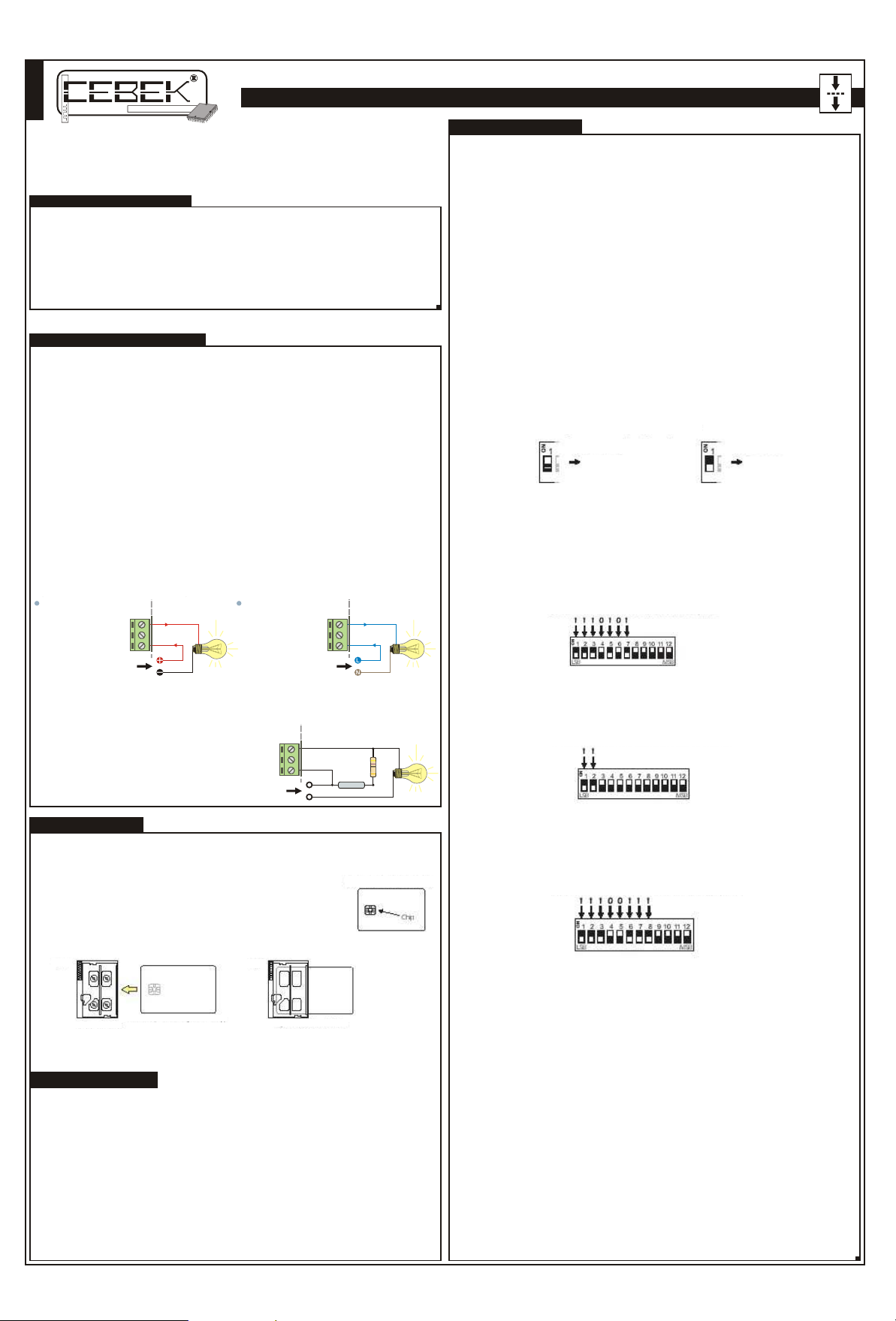
OUTPUT CONNECTION. LOAD. The DA-06 output is controlled by a relay (device electrically insulated from the
circuit) which accepts any device up to 5 A. The relay is not a component supplying voltage but its function
is limited to accept or deny the voltage passage like a standard switch. For this reason, you have to supply
the load through this component.
The relay has three output terminals: The normally open quiescent (NO), the normally closed quiescent (NC)
and the common. Install it between the Common and the NO in accordance with the schedule “Output
Connection. Load”. For the inverse function you have to place the load between the NC and Common.
OUTPUT. CONNECTION OF THE LOAD. Module outputs re controlled by a relay, insultaed device allowing any
load until 5.A. as maximum consumption The relay is not a component supplying voltage, but it's function
is to allow or deny the electrical flow supplied through its contacts, like a standard switch. For this reason, you
have to supply the load through this device. The relay has 3 output terminals the normally open at quiescent
(NO), the normally closed at quiescent (NC) and the common. The operating mode of this mechanism is
the same as a switch with two (2) terminals NO and common as it is indicated in the Fig. Nº1 .
For the inverse function you have to place the load between the NC and Common.
Fig. 2. Ejemplos de Conexión de la Carga.
12 V DC Connection.
Normally Open, (NO)
Normally Closed, (NC)
Common
12 V. D.C.
INFORMATION ABOUT THE OUTPUT. Specially with inductive loads, a relay can generate a fluctuation or an
incorrect output operating mode. In such case, you have to install an anti-spark circuit between both contacts
of the relay used in this connection, as it is indicated on the drawing, to absorb the current peak provoking the
mentioned problem.
If the load connected to the circuit is supplied at
230V, you have to use a X2 type 100nF/400 V
capacitor type and a 47W. ½ W resistor (See fig.
2). If the load is supplied at 12 or 24 V, remove
the resistor and install only a X2 type capacitor
between relay both contacts.
You must try values between 10nF and 47nF till
the fluctuation disappears.
Load,
Device.
230 V AC Connection
Normally Open, (NO)
Normally Closed, (NC)
Common
230 V. A.C.
Fig. 3. Relay anti-fluctuation filter.
NO
NC
Common
Load
Supply
47W 1/2W
100nF
X2
Load,
Device.
Load,
Device.
OPERATING MODE.
OPERATING MODE. The operating mode of the module can be basically divided in two parts or concepts,
the Programming Mode and the Accesses and Balances Control Mode.
CARDS INSERTION. Before to describe the Programming Mode or the Accesses
and Balances Control Mode, you will have to learn to correctly done the cards
insertion operating into the reader. This operating is basic and indispensable for
any circuit operating modes.
Firstly, you have see the fig 2, corresponding to a standard chip card. You will note
that each card include in its reverse part a chip easily identifiable. Place the card
to have the chip downwards in the direction of the reader entrance. See
illustrations fig.3 and fig 4.
Fig.3 Circuit of the reader
Once the card has been correctly oriented, at a normal speed, without abruptness, introduces it through
the groove inside the reader and in the way indicated in the drawing.
Back (card face without chip)
Fig.4 Card inserted in the reader
Fig. 2 Reverse of the card
PROGRAMMING MODE.
See General Wiring Map section. The circuit is composed by three dips batteries, one with 8 (Control), one
with 12 (Data) and a last one with 4 (Credits/Time). Thanks to these batteries and the “Enter” key, you could
do all operations offered by the Programming Mode.
Activation of the Serial number. The first operation that you must do is the activation of the serial number.
Potentially several users with a DA-06, and all users with cards similar to yours. Theoretically, this situation could
allow that any other person without any relation with your module, but with a Cebek Chip card with a
number that you were registered in your module, could consume balances in this one. In order to avoid this
situation, you have to program the DA-06 with a serial number between 0 and 4096 that individualize it and
make it exclusive. The serial number will be registered into the module and into all cards activated with this
one. Then, only cards activated with your DA-06 could operate.
In order to register the serial number, firstly you have to accede to the Programming Mode. Place the DIP 8
(Control) in ON position, automatically LED “PRG” will be illuminated indicating that you have correctly reach
this mode. Then, places DIP 1, (Serial Number activation), also in ON position (the rest of dips, except the 6
must to remain in OFF position), LED “PRG” will start a continued intermittence.
The following step will be to configure on the DATA battery, through the 12 dips composing it, the wished
serial number. Do the combination that you want placing in ON or OFF the 12 dips of the battery. It is a code
with internal purpose for the circuit.
PROGRAMMING MODE.
Once introduced, it will not be necessary to reproduce nor to remember it (except if you combine several
DA-06, then you must to consults the corresponding section).
Once selected the code, you have to press the Enter key. The LED “CONFIRM” will be illuminated and you
have 5 seconds to confirm the order pressing again Enter. If you do it correctly, LED “01” will be illuminated
confirming the correct execution of the serial number activation. Otherwise, if after five seconds you don't
press the Enter key: the module will return to its initial state of Programming Mode, illuminating previously the
Led “ERROR”, without doing any change in the memory of the circuit.
Note. Each time you activate a serial number, the rest of data stored in the module (like card numbers,
etc… will be irrevocably erased.
Cards Recording. The module is supplied with 2 Eeprom Chip cards with 1 Kbyte. Although you can acquire
additional packs composed by 10 units (ref C -7294). It is not important that Eeprom Cards are empty or
not, you have to install data on each card that later allows the module to recognize them.
The recording will have two functions: firstly it will be the assign a number between 0 and 999 that later and
according to the module's programming, will allows its access. Secondly to internally record the serial
number of the circuit on each card, doing it only available for the DA-06 with which cards have been
recorded. This function is automatically and without user's intervention done when the mentioned card
number is activated.
In order To record and to assign a number between 0 and 999 to a card, firstly you have to select on the
DATA battery (12dips) and in binary mode the number you wish to record.
To convert a decimal number to binary number or vice versa you can do it with a scientific calculator. Read
instructions of your calculator regarding this matter. However, normally they have a button with DEC
(decimal) and BIN (Binary) abbreviations. In order to do the conversion from decimal to binary, firstly you
have to place the calculator in DEC mode, then introduce the decimal number. Finally you have to select
the BIN option and the calculator will do the conversion indicating the corresponding binary number. This
number composed by “0” and “1” will be the number you have to assign on the Data battery dips. If you
place any dips in ON position, this one will remain configured as 1. If you place any dips in OFF, the DIP will
adopt the value “0”. Then you could write on the battery the required binary number.
Equivalent to 0
DIP 1 corresponds to the bit with smaller weight. (LSB) whereas DIP 12 is the greater weight. (MSB). It supposes
that you have to introduce the binary number in the opposite way that you write it on a paper sheet.
Example 1. Configuration of the Data battery for the number 87.
Firstly you have to convert the decimal number into binary. The binary equivalent for 87 is 1010111. After the
conversion you can insert the code 1010111, (87) in the battery. Remember that units correspond with DIP 1;
tens with DIP 2: hundreds with DIP 3. etc. Therefore you have to compose the number as it is indicated in the
fig 6. Dips not used, in this case 8, 9, 10,11 and 12 must remain in 0. (OFF).
Example 2. Configuration of the Data battery for number 3.
Repeat the process of the previous example introducing this time binary code 11, (3). As for the example 1,
dips not used, in this case dips 3 to 12. Must remain at 0, (OFF). See fig, 7.
Example 3. Configuration of the Data battery for number 99.
Repeat the process of the previous example introducing this time binary code 11100111, (999). As for the
example 1, dips not used, in this case dips 9 to 12. Must remain at 0, (OFF). See fig, 8.
When you have selected the Number you wish to record: Place the DIP 8 of the CONTROL battery in ON
position to accede to the programming mode. Place also DIP 2 (Card Recording), in ON position. The rest of
dips, Except for 5 and 6 must remain in OFF position. The LED ~PRG~ will blink if you correctly done this
operation .
Then insert the card you wish to record in the reader and press the Enter key. like in the previous function: LED
CONFIRM- will be illuminated and you have 5 seconds to confirm the order pressing again the same key. After
the confirmation, LED ~CONFIRM~ will blink during the recording and finally the LED ~OK~ will be illuminated
indicating the correct conclusion of the operation.
If you don't confirm the order during these 5 seconds, or because of an incorrect card insertion or any other
reason the operation would not conclude successfully, the LED ~ERROR~ will briefly illuminating to indicate
this fact. Once completed the recording, remove the card from the reader and change to the card number
the Data battery.
Repeats the process so many times as cards you wish to record.
We suggest you to print or label each card with the number used to be recorded for its later control, erasure
or checking.
To activate Cards. Once cards have been recorded, to allow module to valid cards access during their
insertion, and then to activate the output, you must activate each card.
From Programming Mode and remember that you have to place DIP 8 of the Control battery in ON position.
LED ~PRG~ would be illuminated indicating that you have successfully reach this mode. The rest of dips,
except 5 and 6 must remain in OFF Position.
Then, insert the previously recorded card and presses Enter key: Like in the rest of previous functions. LED
~CONFIRM~ would be illuminated and you will have 5 seconds to confirm the order pressing Enter again.
After the confirmation, the LED ~CONFIRM~ will blink while the module is registering the card and finally and
the LED ~OK~ will be illuminated to indicate the correct conclusion of the operation. If there is any problem
avoiding the card activation, not allow the discharge. The LED ~ERROR~ will indicate it, briefly illuminating.
Once this operation done, the card will be permanently stored in the memory of the circuit. Later, in the
Accesses Control mode, when the card is introduced the circuit activates the exit.
The module memory will remain unalterable even without electrical supply and you could only be able to
erase data deactivating cards or initializing the circuit through a serial number activation.
fig 6. Configuration of the card number 87, binary code 1010111.
1º. 87 decimal = 101011' binary
2º. To place the Binary number considering LSB and MSB bits.
fig 7. Configuration of the card number 3, binary code 11.
1º.3 decimal = 11' binary
2º. To place the Binary number considering LSB and MSB bits.
fig 8. Configuration of the card number 999, binary code 11100111.
1º.999 decimal = 11100111' binary
2º. To place the Binary number considering LSB and MSB bits.
Equivalent to 1
Page 2
ELECTRONIC
CIRCUITS
ENGLISH.
DA-06DA-06
Electronic purse with Chip Card
PROGRAMMING MODE.
Balances recording. With the DA-06 you can record each card with data concerning the access previously
mentioned, but you can also charge or recharge balances in each cards, up to a maximum of five balances.
Later the user will be able to consume them according to its needs.
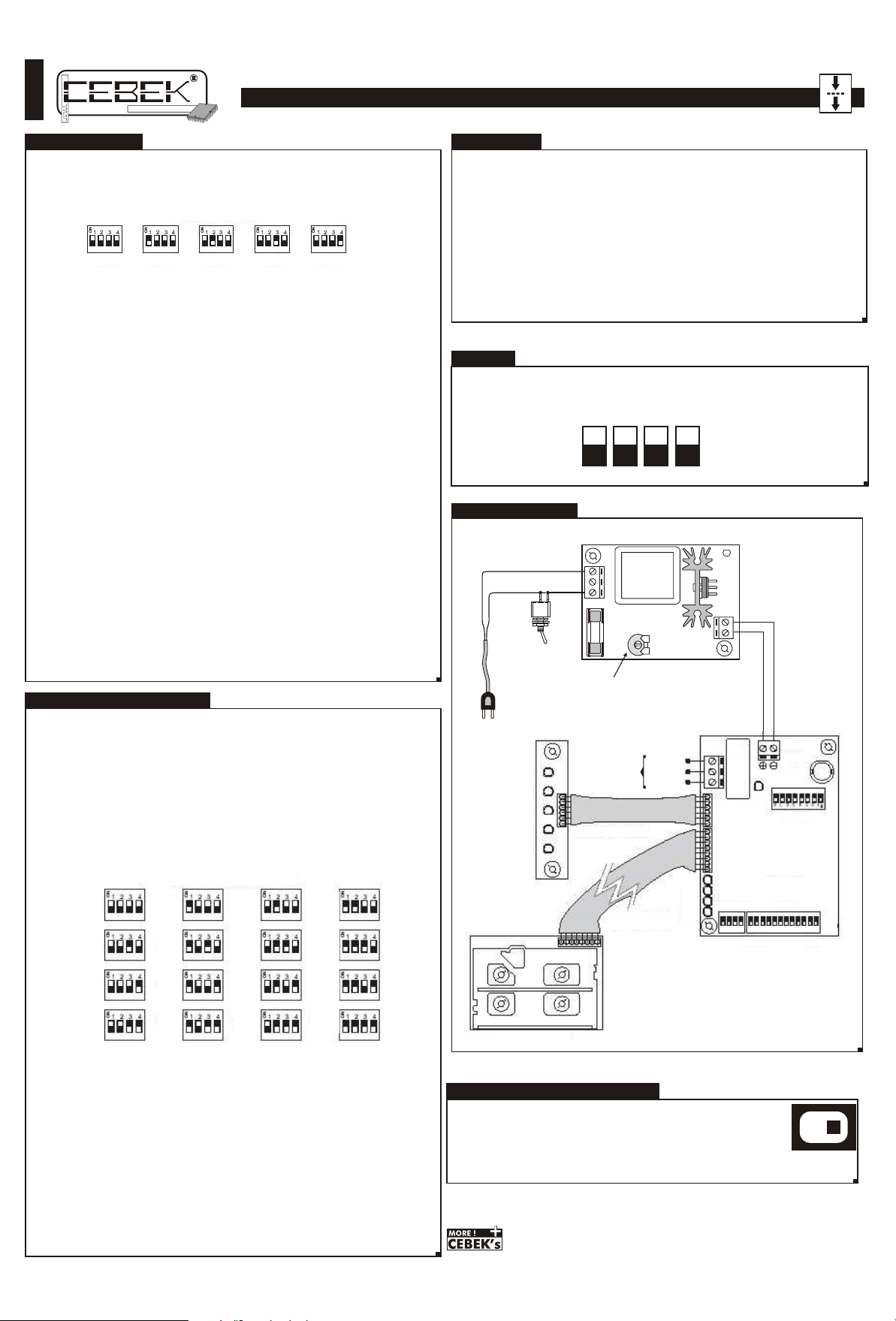
In order to record balances in a card, firstly you have to configure the dips on the Credits/Time battery the
number of wished balances. See fig 9
Fig 9. To select Balances.
1 Balance
Accede to the Programming Mode placing DIP 8 of the CONTROL battery in ON Position. Place also DIP 5,
(Balances Recording) in ON. The rest of dips, except 6, must to remain in OFF position. LED ~PRG~ will blink if
this operation correctly done.
Then, insert the card in the reader and presses the Enter key. Like in the previous function, LED ~CONFIRM~ will
illuminate and you have 5 seconds to confirm the order pressing again the same key. After the confirmation,
LED ~CONFIRM~ will blink during the recording and finally LED ~OK~ will be illuminated indicating the correct
balances recording in the card.
To activate the Serial number through card data. In the corresponding section it is described how to activate
serial number through the Data battery. However, it can be necessary to initialize the DA-06 with the same serial
number than a card previously recorded.
To do this, you must reach the Programming Mode. Remembers that you have to place the DIP 8 of the
Control battery in ON Position. Place also DIP 7 in ON. The rest of dips, except 5 and 6, have to remain in OFF
position, LED ~PRG~ will blink if this operation correctly done. (The rest of dips except 5 and 6 must to be in
OFF.
Then insert the previously recorded card and press the Enter key. Like in the rest of previous functions, 5 sec the
Led ~CONFIRM~ will be illuminated and you have 5 sec. to confirm the order pressing Enter again; after the
confirmation, LED ~CONFIRM~ will blink during the module's configuration with the new serial number. Finally
LED ~OK~ will be illuminated indicating the correct result of the operation. If there was some problem avoiding
to activate the serial number, the LED ~ERROR~ will indicate it, briefly illuminating.
Remembers that each time you activate a serial number, data previously stored in the circuit will be erased.
Note. Remember that if you activate you activate a serial number, the rest of data stored in the module, like
card numbers, etc… will be irrevocably erased.
Combined use of several D0A-06. There are applications requiring several DA-06 installed in different places,
but that all of them must to be compatible. Therefore, with a same card you could activate the access in
some modules whereas in another no. Moreover, you could have cards with access to all the readers and
others only with access to some readers. All this without using a different card type for each reader.
To manage a system composed by several DA-06 and to activate them between them, firstly you have to
assign to each one the same serial number. This operation can be done activating the serial number in a first
circuit and with a card recorded by this one to initialize the rest of DA-06, or through the DATA battery Data
repeating the same process code the serial number activation in all of them. In any mode the result will be the
same.
Later, and with cards recorded with its corresponding identifier number you have to manage in which modules
and which cards will have access to each of them. For instance, if you wish that a card can be used as key for
a system composed by five DA-06, you have to activate each reader: if you needs that a card only has
access in a couple of them, you have to activate it in these two modules and no more. Thus, the balances
consumption will be subject to have access in the corresponding DA-06.
This “Levels” system is the used one in gymnasiums with different accesses to the different services, companies
with different privileges under payment, etc.
2 Balances 3 Balances 4 Balances 5 Balances
DO NOT FORGET.
In the different module functions, you have to check you have placed dips battery as it is indicated in the
corresponding instructions. Selecting by error more than one DIP will provoke an incorrect operating mode of
the function you want to execute.
Do not remove, extend or modify the communication cable between the main board and the reader.
Otherwise, the module doesn't operate correctly and the warranty will be cancelled.
In the module installation, this one must to be insulated from devices that can provoke interferences or network
parasites. Use, if necessary, a network filter and place the circuit in a protected place, far away from these
disturbances.
Do not bend, twist nor dirty cards chip, otherwise can irremediably damage them.
Maintains cards far from direct sun, like car dashboard, windows, or any other place that the excess of heat
can deform the card.
Protects the chip installed on the card from elements that can shred or destroy the copper part composing it.
Do not place the reader in a place where it is not protected from the rain or extreme humidity, because it
doesn't have protection against such elements
The damage because of the failure or omission of these considerations, as well as an incorrect manipulation
will be exempt of the module warranty.
DIP SWITCH
ON
1 2 3 4
GENERAL WIRING MAP.
Led
Power Supply
Mains
Switch
Input
N
L
Fuse
100 mA.
Transformer
Module
FE-103
Máx.
Mín.
ACCESS CONTROL & BALANCE MODE.
The balance and access control mode configure the circuit to do a single function: to read the introduced
card, to deny or accept the access according to its registry in the circuit memory and if this one has balances,
to consequently activate the relay output during the selected time. In any case it will accept programming
functions.
In order to establish the DA-06 operating in Balances and Access control mode Control, check the DIP 8,
(Programming), of the Control battery one is in OFF Position. The module will confirm this situation extinguishing
all Leds on the main board. From this moment, the module will exclusively operate as Balances and Access
control device.
Time per Balance. Each time the user will consumes a balance, the exit will be activated. The time that this
one remains connected will depend on the previously assigned time per balance.
The time selection per balance can be only done in the Balances and Access control device mode, through
the dips of the Credit/Time battery.
The module admits a time per balance: 1 minute as minimum and of 120 minutes as maximum. See fig 10
and configure the Dips battery the wished time.
Fig. 10 To select time per Balance
1min
5 min.
40 min.
80 min
Balances Consumption. In order to activate the circuit output, firstly the user have to introduce the chip card
in the reader, and then to press the Enter key. Automatically the circuit will discount and consume a balance
from the card, activating the output during the pre-assigned time per balance.
Later the user will be able to remove the card, the output will not be deactivate up to the end of the timing.
Until then, the module will not accept the consumption of a new balance.
During the consumption of a balance, the state Leds, initially lighted on will be progressively lighted off
according to the time up to the end of the balance.
Each one of these five Leds will indicate with 20%, 40%, 60%, 80% and 100%, the consumed percentage. A
complementary illuminated Led indicates that the indicate percentage is still available. An intermittent LED
will indicate that half of that percentage has been consumed, and a lighted off LED will indicate that this
percentage has been consumed.
Indication of balances and cards state. When the user introduces a chip card in the DA-06, if it wasn't be
previously activated, the LED Error blinks until you remove the card from the reader. If at the opposite the card
was previously activated, the module remains you press Enter and start the consumption of a balance.
Each time you press Enter, if the card has no balance, the five state leds will blink until the card is removed
from the reader.
If the card had balances, when Enter is pressed the module will initially indicate how many balances are
available in the card illuminating the corresponding number of state Leds. When Led OK on the main board is
lighted off, state Leds will change their indication to indicate the time of the balance consumption.
2min
10 min.
50 min.
90 min
3min
20 min.
60 min.
100
Min
4 min
30 min.
70 min.
120
Min
230 V.A.C.
20%
40%
60%
80%
100%
Reader Circuit
State Leds board
Communication cable
Reader - Main board
Output
NO
Common
NC
Prg
Valid
Error
Ok
Work
DA-06
Credit/Time
1 2 3 4
MSB
TECHNICAL SUPPORT AND INFORMATION.
For any questions or more information:
By Fax. (24h.) +34.93.432.29.95 By Mail: C/ Quetzal, 17-21, Entlo. 2º
(08014) BARCELONA - SPAIN.
By E-Mail: [email protected]
Keep you invoice. For any repairing could you send this with module.
Else, the module will lost the warranty.
All the module’s CEBEK have 3 years of total warranty in thecnical
repairing, and spares from the date of buy.
CEBEK is trade make of FADISEL S.L. more than 300 module’s are avaible
in stock for any purpose request our CATALOGUE, or visit our Web site
www.cebek.com
Module
Data
Power
Enter
Control
1 2 3 4 5 6 7 8 9 10 11 12
LSB
GARANTIA
3
GARANTIE
WARRANTY
ON
AÑOS
TO
TAL
ANNÉ
YEARS
ANYS
Rev. 0534
GARANTIA
 Loading...