

Page 1
UNIVERSAL TIMER
from 2 to 45 min.
I-2
TECHNICAL CHARACTERISTICS
Voltage. ............................................................. 12 V. DC.
MinimumConsumption. ..................................... 15 mA.
MaximumConsumption. .................................... 60 mA.
Sizes. ................................................................ 76 x 43 x 30 mm.
MinimumTiming. ............................................... 2 minuts.
MaximumTiming. .............................................. 45 minuts.
MaximumLoad. ................................................ 5A.
Protection against Inversion Polarity, (P.I.P.). ... Yes.
TheI-2 module is a standard timer. It will maintain activated the output till the end of the timing.
Theadjustment is done thanks to the potentiometer inserted in the PCB.
It could be activated by supplying or closing its contacts thanks to a push button.
It includes indicator LED and Jumper to extract the potentiometer at the exterior.
INSTALLATION
POWER SUPPLY : The I-2 circuit had to be supplied by a 12 VDC power supply correctly filte red. We recommend you to
use the FE-2 power supply, which has been developed to perfectly answer to the circuit needs.
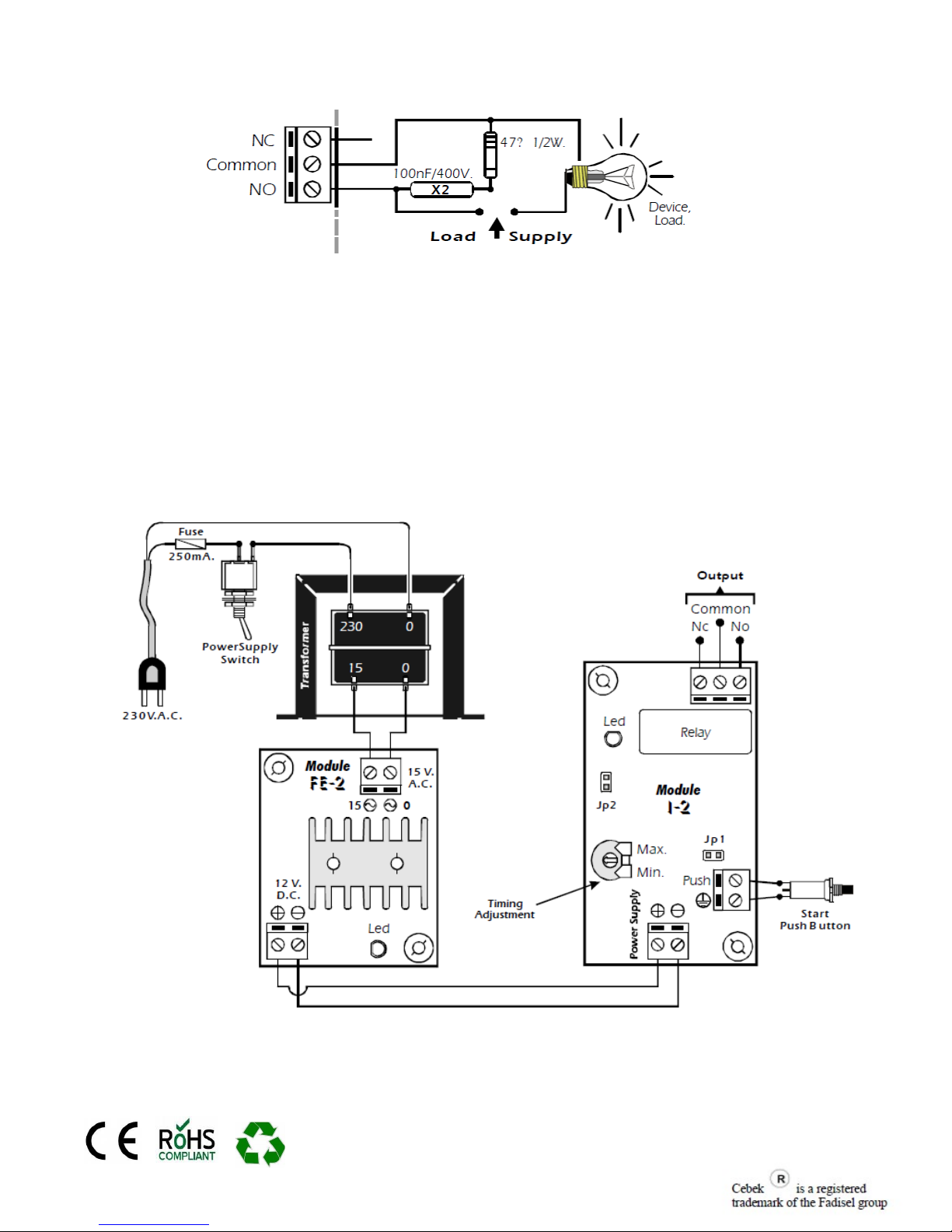
Install a fuse and a switch has itis indicated on the schedule. Both are necessary for the module's protection as well as for
your own safety, as it is required by the "CE" regulations.
Connect the positive and the negative of the power supply to the respective positive and negative terminals of the module,
indicated in the wiring map. The distance between the power supply and the module has to be as short as possible. Verify
that the assembly is correct.
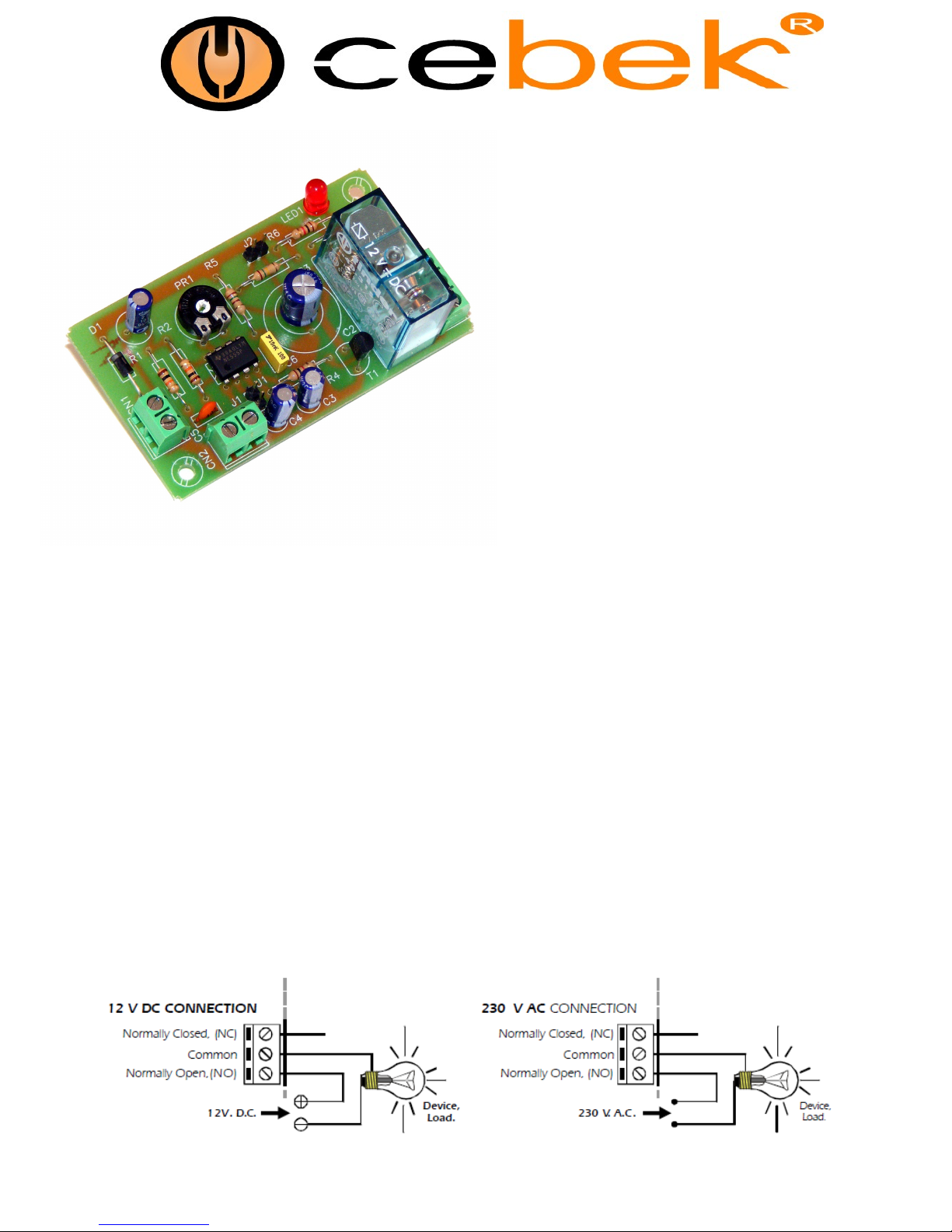
OUTPUT CONNECTION . LOAD : The I-2 output is controlled by a relay, and accepts any device up to 5 A. The relay
is not a component supplying voltage but its function is limited to accept or deny the voltage passage like a standard switch.
For this reason, you have to supply the load through this component.
The relay has three output terminals: The normally open quiescent (NO), the normally closed quiescent (NC) and the
common. Install it between the Common and the NO in accordance with the schedule "Output Connection. Load".
For the inverse function you have to place the load between the NC and Common.
Page 2
I-2
INFORMATION ABOUT THE OUTPUT : During the operating mode and according to its load, it could happen a
fluctuation or an incorrect working of the output. In such case, you have to install an anti-spark circuit (100 nF/400V
Capacitor type X2 and 47 . ½ W resistor) between both contacts of the used relay, as it is indicated on the drawing.
OPERATING MODE : The timing adjustment is done adjusting the potentiometer inserted on the PCB. At beginning you
have to place the potentiometer at the minimum, after you could adjust it accoridng to your wished time.
Once the time selected, the module I-2 could be activated according towdifferent modes: Activation by push button or
supplying the module. To activate the module thanks to the push button, you have firstly toinstall a quality push Button
between indicated terminals. See the General Wiring Map. Each time you activate it, and if the previous timing is completely
finish, the module will be activated, lighting the LED and exiting the relay duringthe selected time.
To activate the I-2 each time you supply the module, with out using the push button, you have to connect both terminals of
the JP1 jumper. Then, each time you supply the module, the timing will be automatically activated.
INSTALLATION OF THE EXTERNAL POTENTIOMETER : If you wish to remove the potentiometer already inserted on
the PCB and install an external potentiometer, you have to firstly desold the resistor fromthe circuit. Then, install two
connection wires fromthe JP2 Jumper till the new potentiometer. This one has to be a Linear 4M7 potentiometer.
GENERAL WIRING MAP.
 Loading...