

Page 1
SHOWER SOFTENER-CEASA 1
Page 2

2 SHOWER SOFTENER-CEASA
Application: The product is mainly used for shower water softening, but can also be used for
floor heating, beauty salons, hairdressing salons, washing machines etc.
The softener water is not drinkable.
Please note:
1. Due to occasional updates, some of the text or designs in the manual
may differ from the actual product. Please refer to the actual product.
2. All data has been carefully checked. If there are any printing or
content errors, we reserve the right of interpretation.
Page 3

SHOWER SOFTENER-CEASA 3
Table of contents
1. Product list…………………………………………………………………………………………………………………………………5
2. Product overview……………………………………………………………………………………………………………………….6
2.1 Characteristics
2.2 Technical Parameters
2.3 Technological Processing of Water
2.4 Appearance and Dimensions
2.5 Structure
3. Installation………………………………………………………………………………………………………………………………….8
3.1 Installation Instructions
3.2 Product Installation
3.2.1 Preparation of Tools
3.2.2 Installation Position
3.3 Pipeline Installation Instructions
3.3.1 Installation after Water Heater
3.3.2 Installation before Water Heater
3.3.3 Drain Pipeline Installation
3.3.4 Power Wire Installation
4. Trial Run……………………………………………………………………………………………………………………………………22
5. Regeneration Operation……………………………………………………………………………………………………………22
5.1 Water Capacity
5.2 Regeneration Salt Consumption
5.3 Regeneration Process
6. Resin Replacement……………………………………………………………………………………………………………………25
7. Parameter Setting…………………………………………………………………………………………………………………….28
7.1 Product Control Panel Overview
7.2 Main Board Socket Overview
7.3 Product Installation Mode Setting
7.4 Regeneration Reminder Day Setting
7.5 Meaning of Operation Codes
8. Troubleshooting……………………………………………………………………………………………………………………….31
9. Warranty Card………………………………………………………………………………………………………………………….32
INDEX
Page 4

4 SHOWER SOFTENER-CEASA
1. If accessories are required, please purchase superior quality products.
2. Given the particular nature of the environment where the product is used, all the components of
the shower softener have a certain service life. The service life of the main components is listed
in the user manual. Please replace components in accordance with the requirements.
3. The user manual provides guidelines for the correct use of this product. Please strictly follow
the user manual instructions regarding operation, routine inspection and maintenance.
4. We recommend that this product is installed by a qualified professional appointed by the
company authorized distributor. Users must provide details about the mounting surface (such as
the installation surface material, water and electrical layout) for installation.
5. This product is suitable for municipal tap water, with a water pressure of 0.1~0.6 Mpa and a
water temperature of 5℃-70℃. Not permitted for use outside this range.
6. The product is only suitable for indoor installation and use. It must be installed in a cool and dry
place, away from direct sunlight. Avoid exposing the pipe connected to the product to light, heat,
corrosive environments and impact from sharp objects.
7. This product should be installed at around 1 meter from a reliable worldwide floor drain for
drainage.
8. Never spray water on this product.
9. In case of product failure, please cut off the water supply and contact your distributor as soon as
possible.
10. In order to ensure efficient regeneration, please use our company-approved regeneration salt
particles where possible.
11. If the transformer and wire are damaged, they must be replaced at our factory.
12. Since the product needs electricity to operate, please do not install the transformer in a location
where water splashes are possible.
13. Our company shall not be liable for any damage resulting from operation not in accordance with
the above considerations.
NOTICE
Page 5
SHOWER SOFTENER-CEASA 5
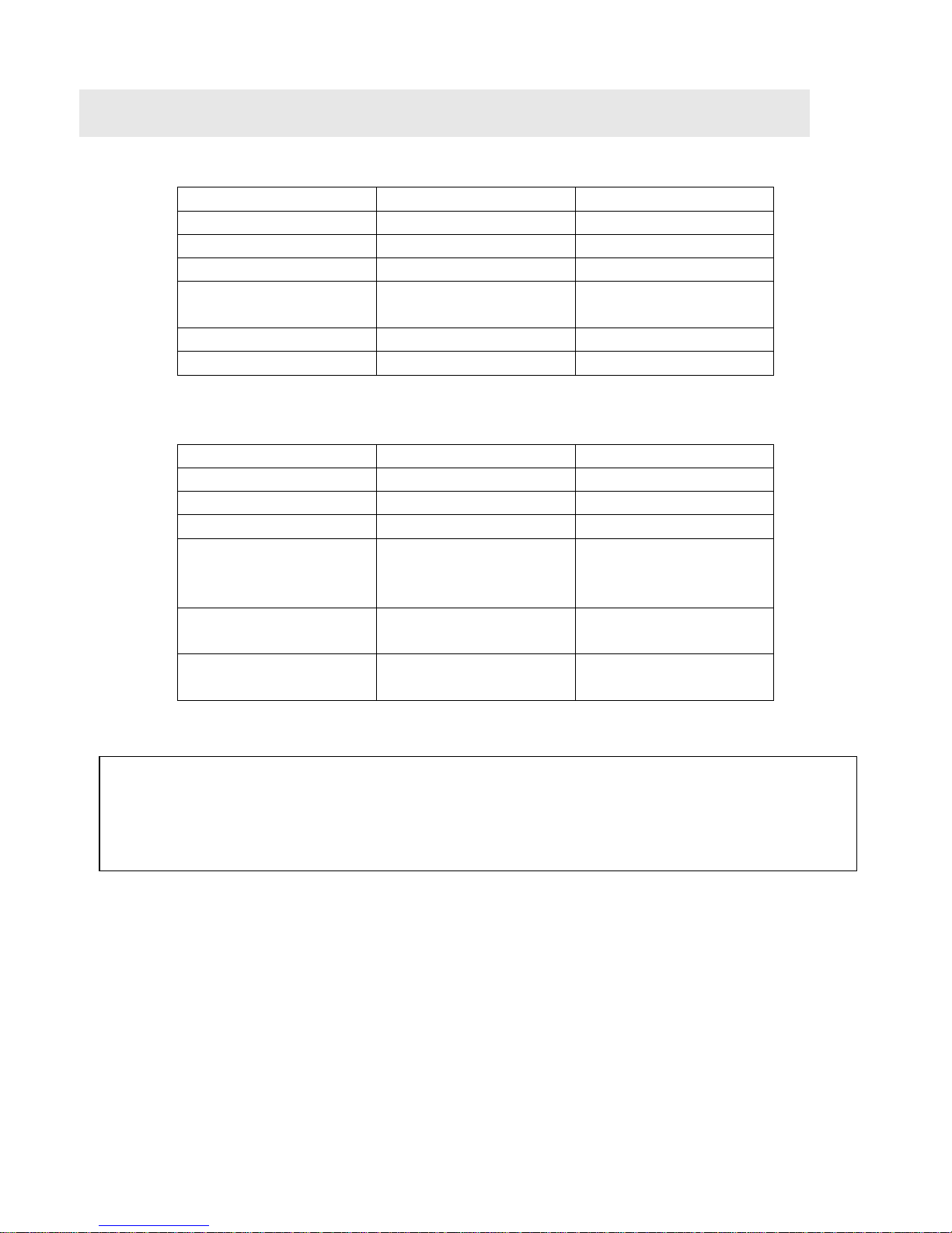
Name
Quantity
Remarks
Shower softener
1
Stainless steel plate
1
Transformer
1
3 meters
Accessories
1
Expansion
tube/screw/gasket
User manual
1
Certification
1
Optional accessories
Name
Quantity
Remarks
Braided hose
1
600mm
Cut-off filter
1
¼" Drain pipe
3
Cold water connector
1
Installation before the
water heater
Hot water connector
1
Installation before the
water heater
½" Elbow
1
Installation before the
water heater
1. PRODUCT LIST
Note: Optional accessories are required to install the product before the water heater.
If needed, please purchase from your distributor.
Page 6
6 SHOWER SOFTENER-CEASA
2.1. Characteristics
●Wall-mounted, no brine tank, small volume.
●Dynamic regeneration mode. Higher water capacity. Save salt and water.
●Extensive applicability: installation before or after the water heater. Installed before
the water heater, it prevents scaling in the heater.
●Automatically controlled regeneration time, one button to perform regeneration. No
need for human supervision. LED display.
●Days of use reminder, next regeneration time display.
●Automatic backwash function that reduces resin hardening and strainer blockage to
improve resin service life.
●Built-in quick connector for easier maintenance and resin replacement.
●Outlet with check valve to prevent the backflow of water from the water heater.
●Data saved after power off.
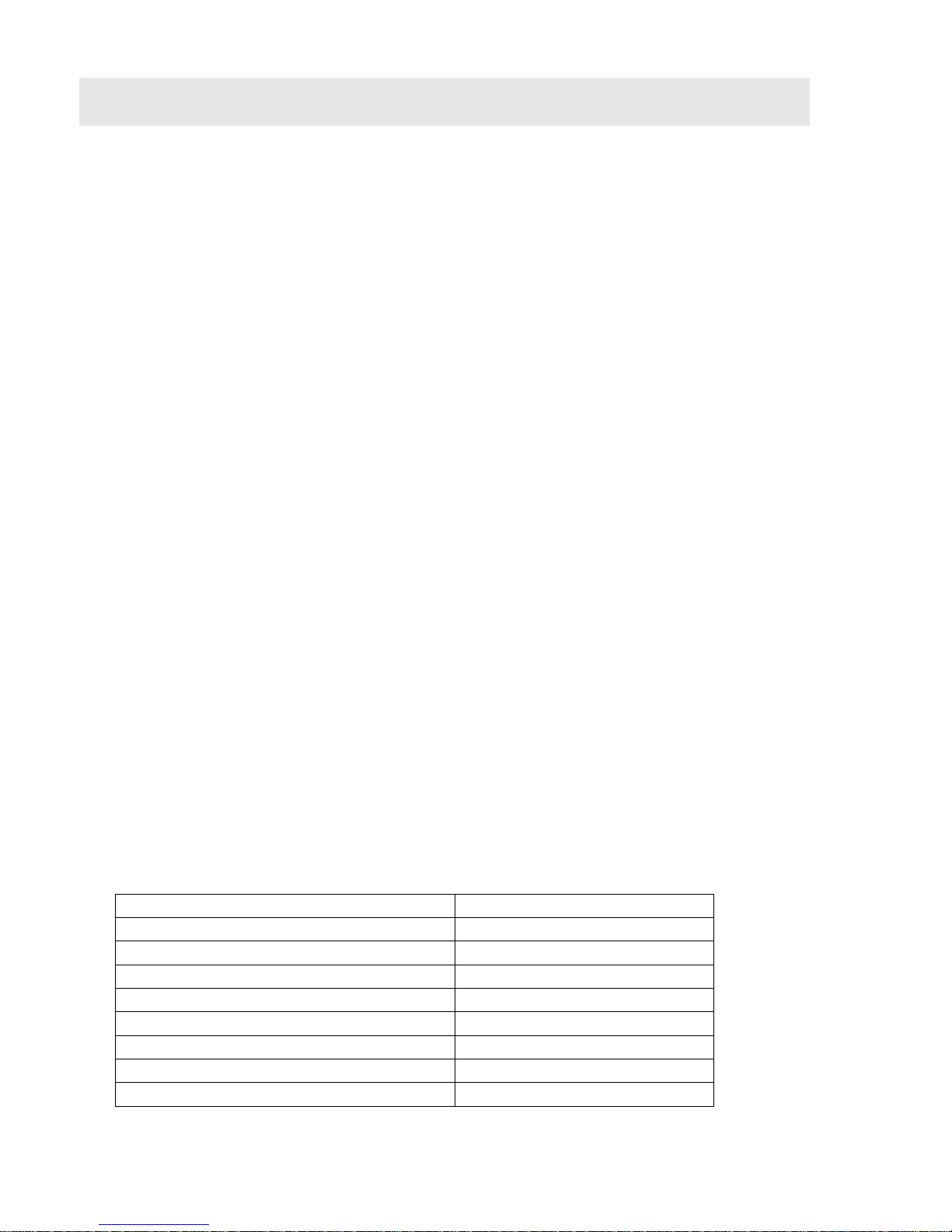
2.2. Technical Parameters
Item
Requirements
Work Pressure
0.1~0.6MPa
Water Temperature
5℃~70℃
Environment Temperature
5℃~50℃
Transformer
AC100~240V/50~60Hz
Water regeneration capacity
750L
Water inlet/outlet specification
G1/2
Regeneration salt consumption
400g
Suitable water
Tap water
2. PRODUCT OVERVIEW
Page 7
SHOWER SOFTENER-CEASA 7
Water quality: Conform to the “Health safety evaluation specifications and functions
for drinking-quality water processors -- general water processors” (2001)
All operating parameters for this product have been measured under standard test
conditions (total water hardness test in CaCO3, 200 mg/-), and will change under
different operating conditions
2.3. Technological Processing of Water
Tap Water Na cationic resin Soft water
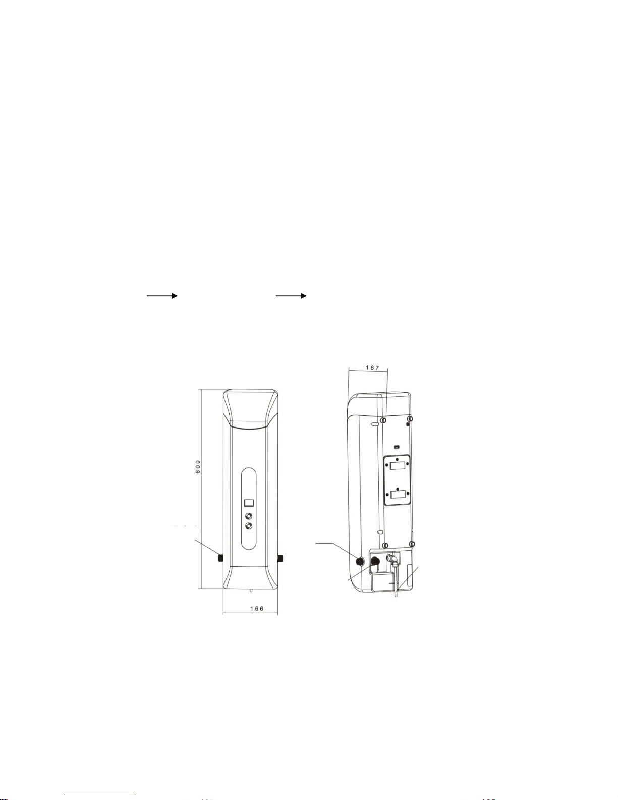
2.4. Appearance and Dimensions
Product Diagram
Drain pipe
Outlet
Inlet
Page 8
8 SHOWER SOFTENER-CEASA
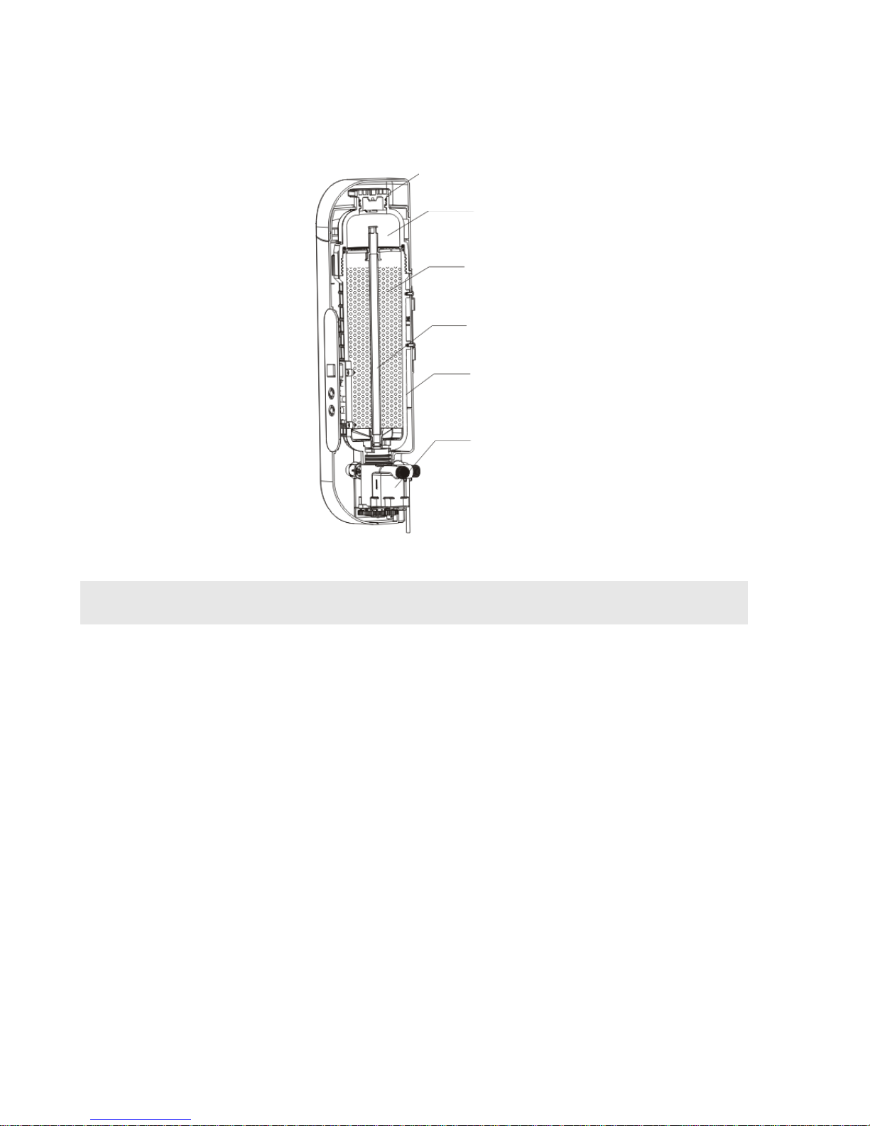
2.5. Structure
3.1. Installation Instructions
This product can be installed in one of two ways:
A. Installation before the water heater
Advantage: Softens water first, then heats it, to prevent scaling in the water heater,
save energy and protect the environment, and soften the bathing water.
B. Installation after the water heater
Advantage: The installation after the water heater is convenient for pipeline
installation, softens the bathing water, and is suitable for users looking to decorate.
Salt tank cover
Soluble salt tank
Resin
Riser pipe
Resin tank
Control valve
3. INSTALLATION
Page 9

SHOWER SOFTENER-CEASA 9
The installation method must be chosen between the above two according to the
user’s needs.
3.2. Product Installation
This product features a wall-mounting system. Please rely on a professional for the
installation. If you decide to install it yourself, please follow the steps below.
3.2.1. Preparation of Tools
The following tools are required for installation: adjustable wrench, pipe wrench,
screwdriver and percussion drill.
3.2.2. Installation Position
(For details on the product installation method to determine the installation position
and pipe connection, please refer to the pipe installation instructions in the user
manual).
When this product fails to use the resin, salt needs to be added for the regeneration. In
order to add salt, the user can choose at what height to hang the product based on
their own height. This product should be installed at around 1 meter from a reliable
worldwide floor drain.
Product wall-mounting steps:
2.1 Open the package and check if the softener is complete and all accessories
are included.
Page 10
10 SHOWER SOFTENER-CEASA
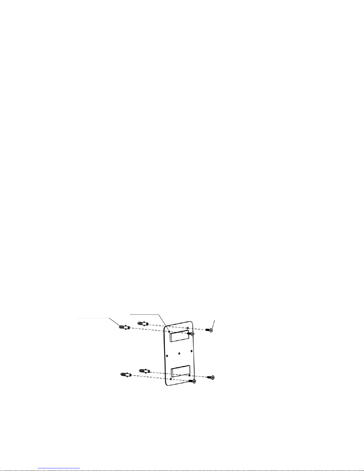
2.2 Remove the expansion screws and stainless steel plate. Use the holes in the
plate as a reference to mark the drilling locations on the wall using the
percussion drill. Our company provides expansion screws for ST3.9 x30, so
we recommend selecting a 6 mm diameter drill bit. When selecting the height
to hang the product, please give priority to what is convenient for you in terms
of adding salt.
2.3 Normally the stainless steel plate can be installed using just four expansion
screws in a diagonal pattern in soft walls, such as wood, lime… Installation
under other special conditions may require more screws. Please refer to figure
1.
2.4 Insert the expansion screw tube into the drilled hole, then use a screwdriver
to fix the plate to the wall, as shown in figure 2, with the raised side facing
outwards.
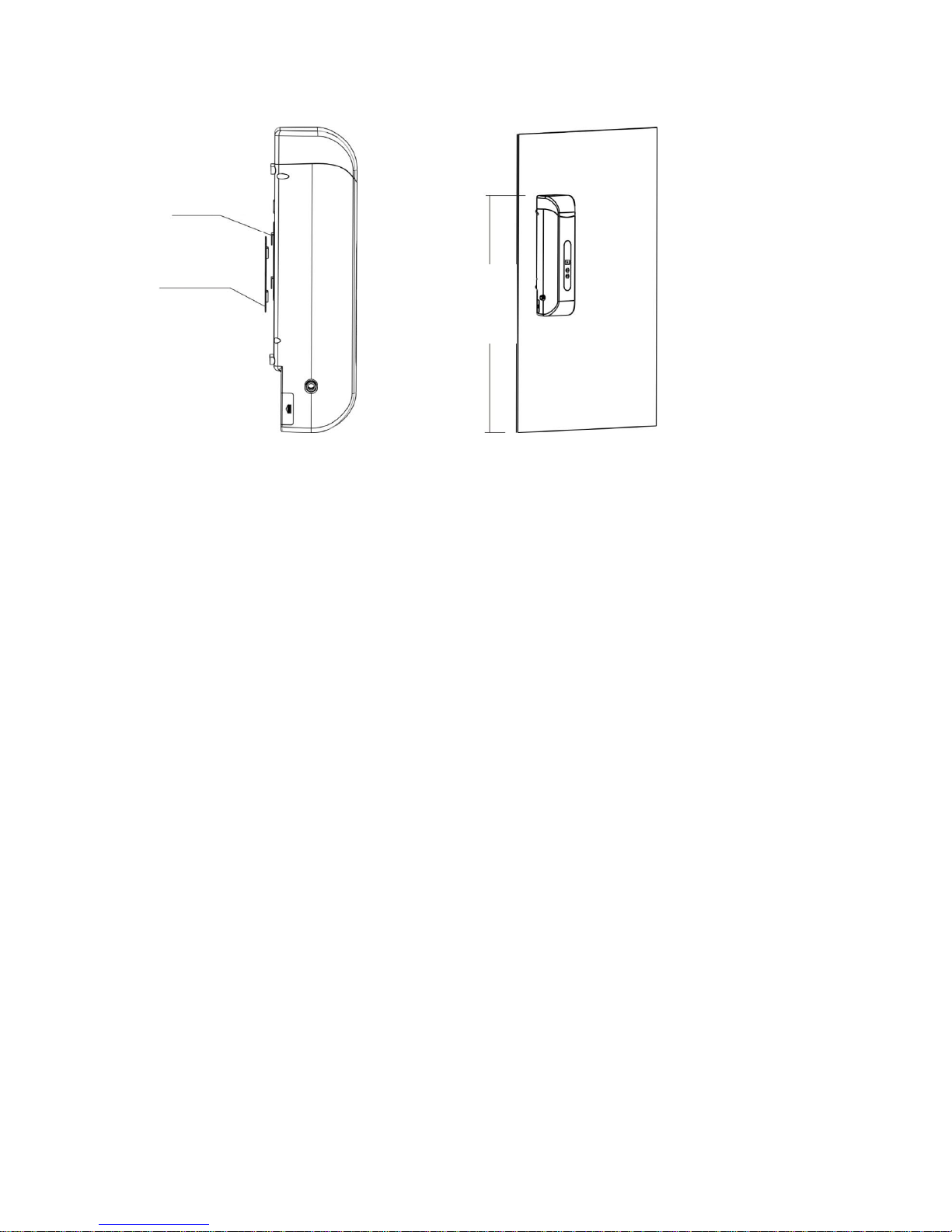
2.5 Install the unit on the slots of the fixed plate, then complete the hanging
process. The appearance after installation is shown in figure 3.
Figure 1. Install the stainless steel plate
Expansion screw tube
Stainless steel plate
Self-tapping
screw
Page 11
SHOWER SOFTENER-CEASA 11
Figure 2. The unit is fixed to the wall Figure 3. Appearance after installation
3.3. Pipeline Installation Instructions
3.3.1 Installation after Water Heater
Reminder: If there is no spare faucet in the bathroom, there will be no water flow
during regeneration. Please reserved a spare outlet for this purpose during
installation.
Installation steps:
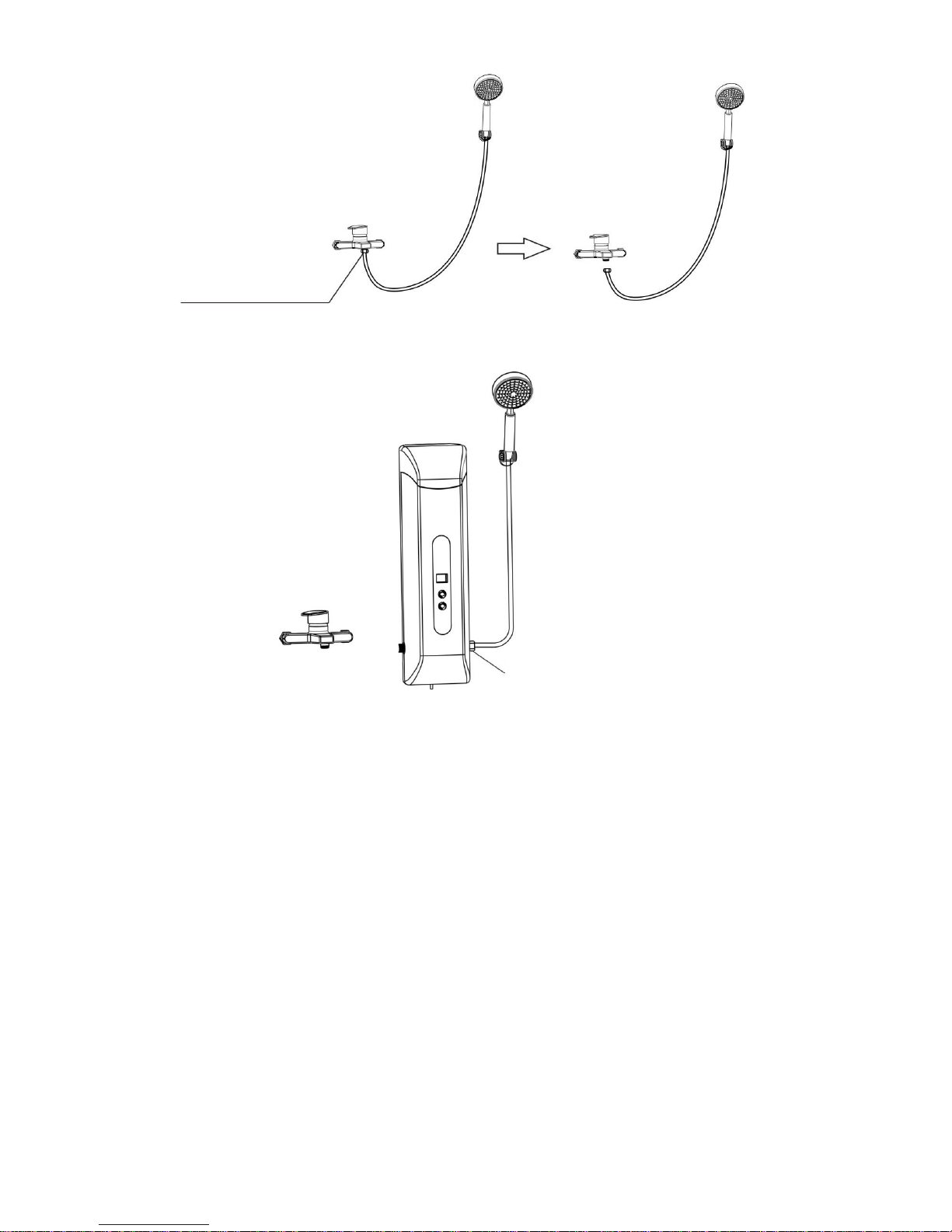
1.1 Close the water mixing valve; use an adjustable wrench to unscrew the hand-held
shower nozzle and the nut from the water mixing valve connection as shown in
figure 4. Tighten the nut of the shower head to the outlet of the unit, as shown
in figure 5.
Fixed unit
Plate
mounted on the wall
Suggested height:
less
than 1.7 meters
Page 12
12 SHOWER SOFTENER-CEASA
Figure 4. Unscrewing the shower nozzle and nut from the water mixing valve
Figure 5. The nozzle is tightened to the unit
1.2 Connect the outlet of the water mixing valve to the unit inlet connection with a
braided hose or bellows. To select the installation location for the unit,
determine the water pipe connection. This manual describes several common
installation methods as a reference for the user.
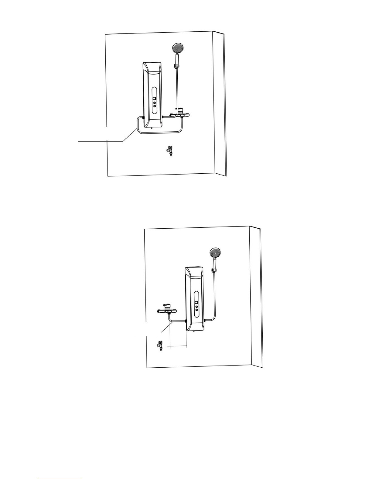
a. If the surrounding space already has a spare faucet installed, the unit can be
installed to the left or the right of the water mixing valve depending on the
space available, as shown in figure 6 and figure 7.
Unscrew the nut
with a wrench
The nut of the nozzle is
tightened to the unit
Page 13
SHOWER SOFTENER-CEASA 13
Figure 7. Installation diagram of the unit on the right side of the water mixing valve
Bellows joint recommended
Figure 6. Installation diagram of the unit on the left side of the water mixing valve
Use bellows joint or tube
Suggested distance:
less than 300mm
Page 14
14 SHOWER SOFTENER-CEASA
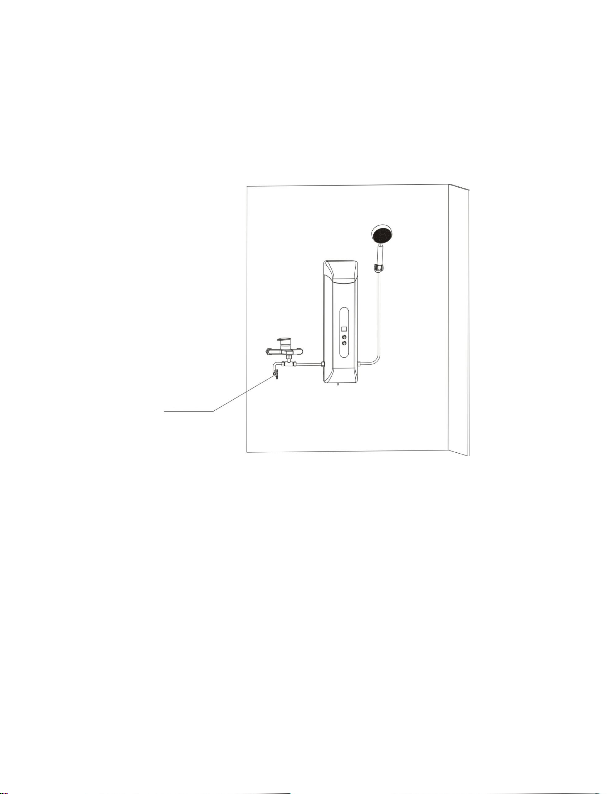
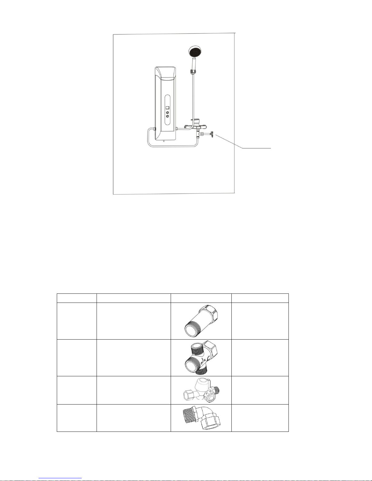
b. If the surrounding space has no spare outlet and water is needed for
regeneration, we recommend installing the unit on the reserved outlet in the
water mixing valve outlet pipe, to the left or the right of the water mixing valve
depending on the space requirements, as shown in figure 8 and figure 9.
Figure 8. Installation diagram of the unit on the right side of the water mixing valve using the reserved outlet
Reserved outlet
Page 15
SHOWER SOFTENER-CEASA 15
Figure 9. Installation diagram of the unit on the left side of the water mixing valve using the reserved outlet
3.3.2. Installation before Water Heater
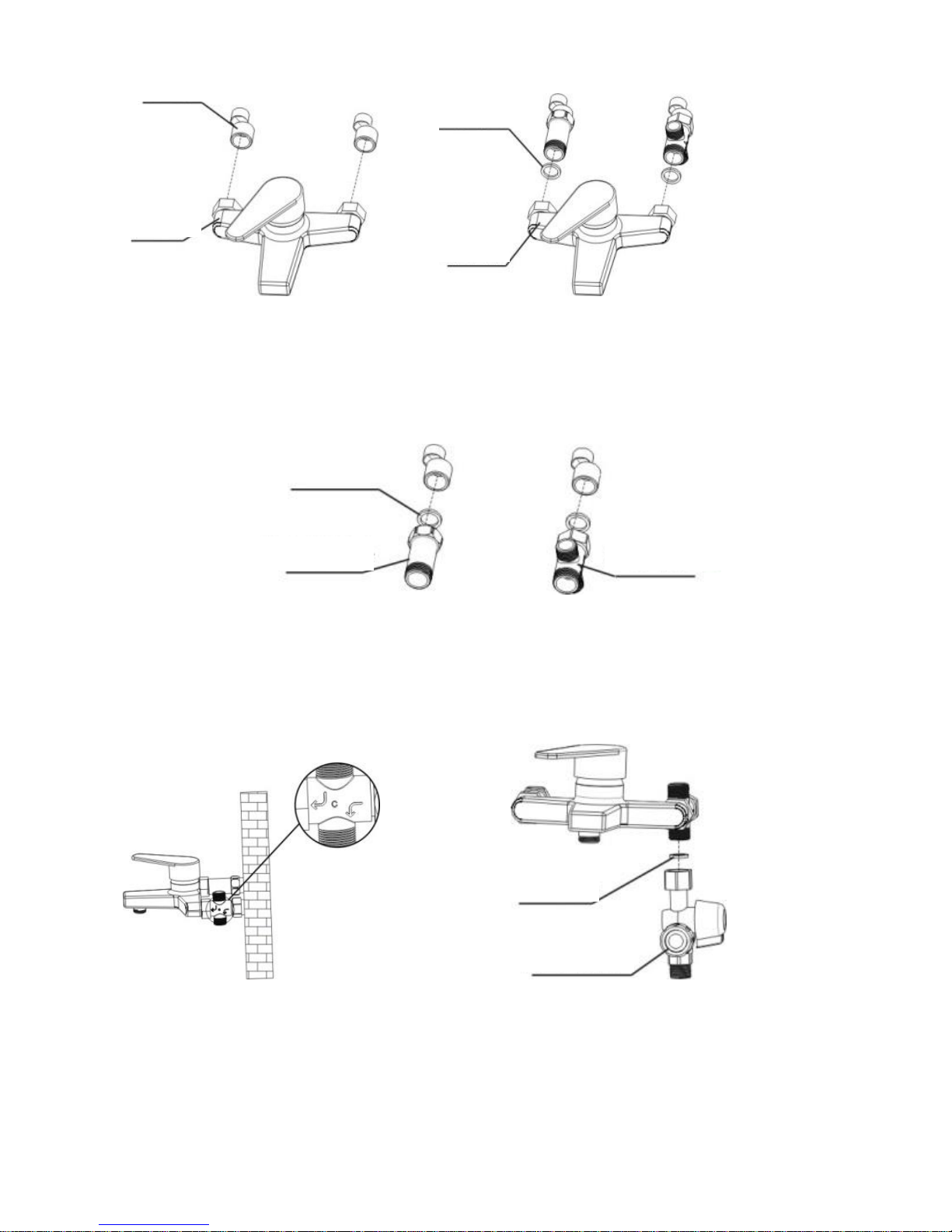
Note: Installation before the water heater is relatively complicated and requires
some accessories that must be purchased from a dealer.
Required accessories
No.
Name
Diagram
Remarks
1
Hot water connector
On the connector
engraved with “H”
2
Cold water connector
On the connector
engraved with “C”
3
Cut-off
filter valve
Selection
4
½" Elbow
Reserved outlet
Page 16

16 SHOWER SOFTENER-CEASA
Below are the installation steps for installation before the water heater
Install the cold and hot water connectors
a. Shut off the water supply, remove the water mixing valve with a wrench,
keeping the center distance of the eccentric connection invariable, as shown in
figure 10.
b. Take out the cold and hot water connectors and ¾" flat gasket from the
accessories box. Refer to the chart to remove the cold and hot water connectors
installed on the wall from the eccentric connections, taking care not to damage
the flat gasket, as shown in figure 11.
c. Use the wrench to connect the cold water connector of the water mixing valve
to the cold water connection, and the hot water connector to the hot water
connection, taking care to maintain the integrity of the flat gasket, as shown in
figure 12.
d. Following the diagram of the installed water mixing valve and the signs on the
connection, place the cold water outlet facing down, as shown in figure 13.
e. In order to prevent large particles from entering into the softener from the
pipeline, which could affect the operation, we suggest that users install a cut-off
filter valve. Take out the cut-off filter valve and flat gasket, tighten the cold
water connection to the tap water connection, placing the flat gasket as shown
in figure 14. Appearance after installation is shown in figure 15.
Page 17
SHOWER SOFTENER-CEASA 17
Figure 10. Disassembled water mixing valve Figure 11. Water mixing valve installed on the connector
Figure 12. Installation of cold and hot water connectors
Figure 13. Appearance after installation Figure 14. Installation diagram of cut-off filter valve
Eccentric connector
Water mixing
valve
Flat gasket
Water mixing
valve
¾" Flat gasket
Hot water port connector
Cold water port connector
½" flat
Cut-off filter valve
Page 18
18 SHOWER SOFTENER-CEASA
Figure 15. Appearance after installation of cut-off filter valve
3.3.3 Drain Pipeline Installation
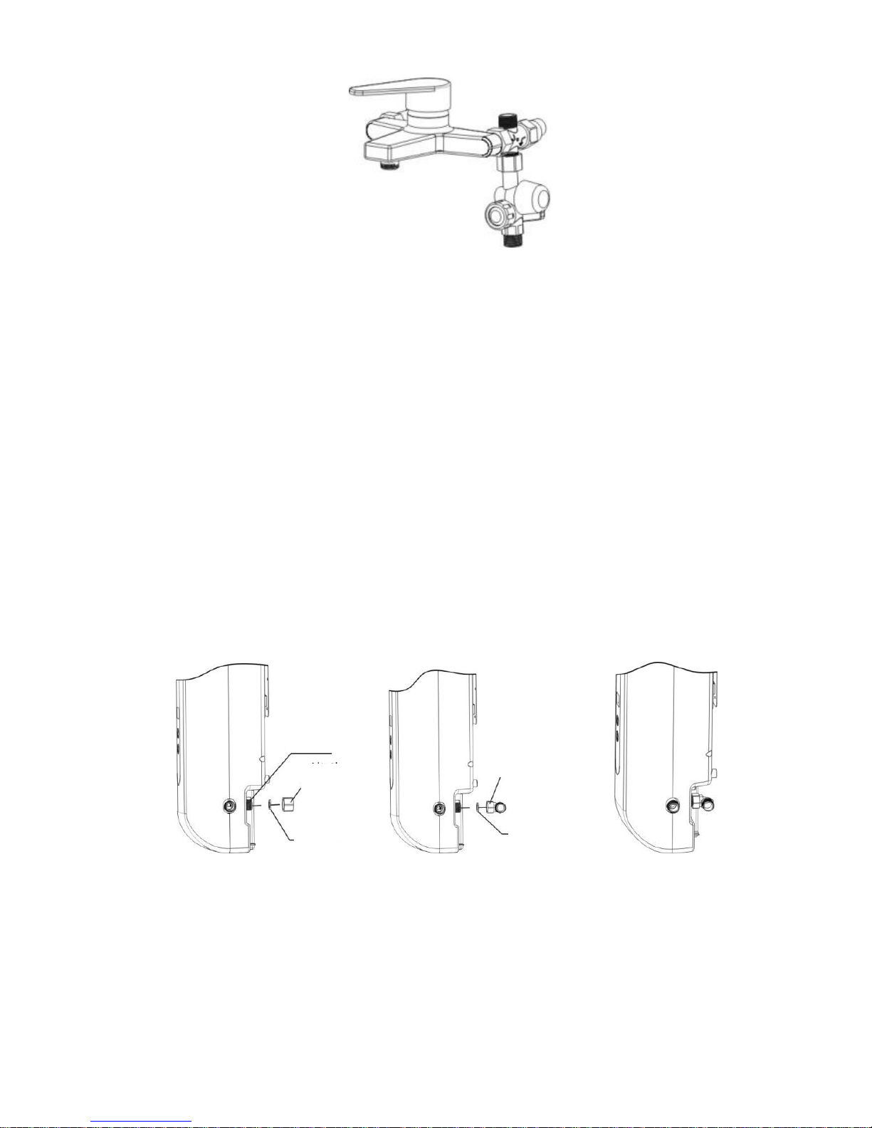
a. Connect the ½" articulated elbow to the outlet behind the unit. Remove the
end cap from the outlet behind the unit as shown in figure 16. Take out the ½"
articulated elbow from the accessories box and tighten it to the outlet as shown
in figure 17, with the flat gasket. Appearance after installation is shown in
figure 18.
b. Choose the appropriate position to hang the unit on the wall (with reference to
the previous product installation instructions).
Figure 16 Figure 17 Figure 18
Back outlet
End cap
½" Flat
½" Articulated
elbow
½" Flat
Page 19
SHOWER SOFTENER-CEASA 19
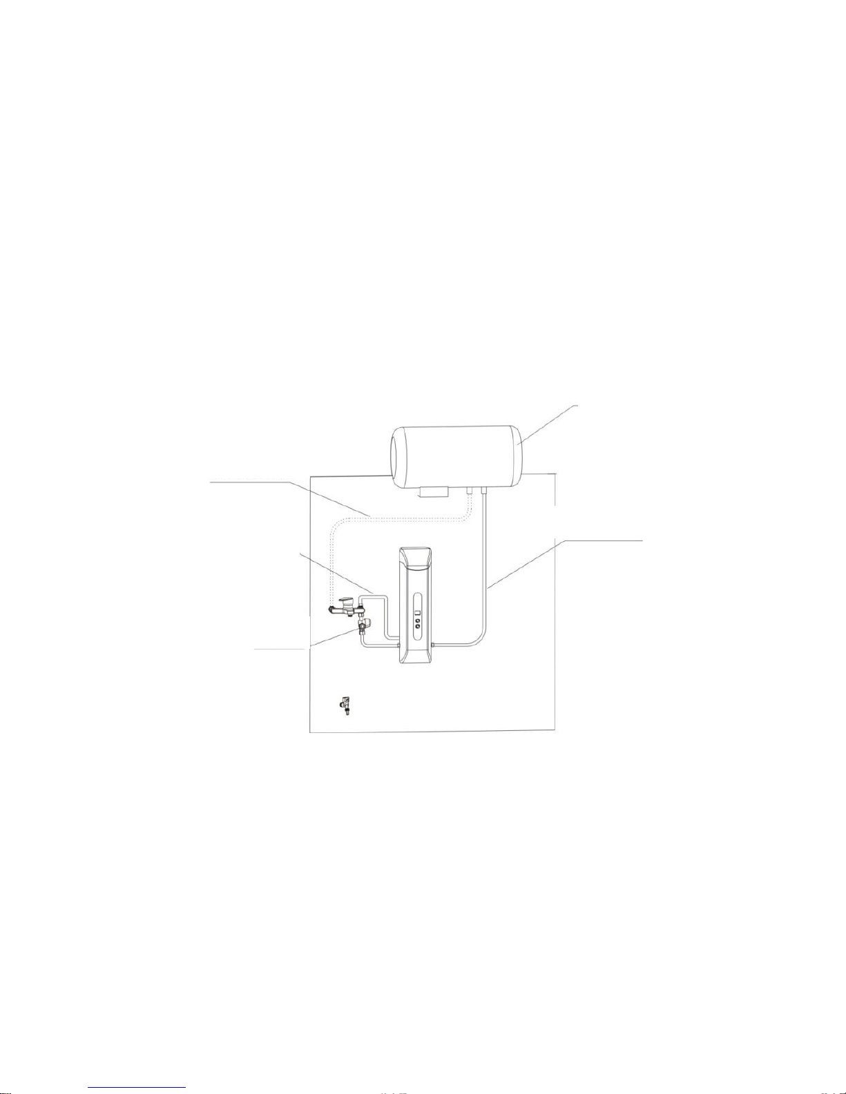
c. Use a braided hose or corrugated pipe to connect the water inlet to the unit,
connect one outlet to the inlet of the water heater and another outlet to the cold
water port of the water mixing valve.
Please keep in mind that the product will have no water flow during
regeneration. If the users need water during regeneration, then we suggest
reserving a spare outlet when installing the domestic water supply pipe. For
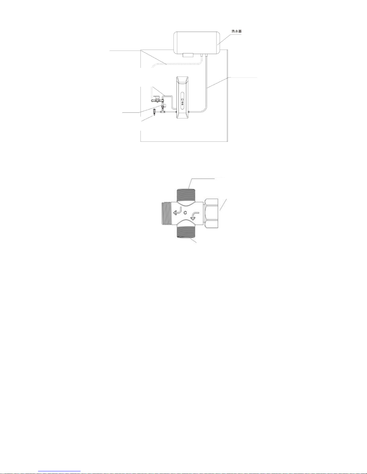
customer reference, figure 19 and figure 20 show a common installation
diagram. Figure 21 shows a closeup of the cold water connection.
Figure 19. Diagram of installation before the water heater
Embedded pipe installed
Water heater
Outlet connected to cold water
connection
Outlet connected to water heater
Cut-off filter valve
Water heater
Page 20
20 SHOWER SOFTENER-CEASA
Figure 20. Diagram of installation before the water heater reserved outlet
Figure 21. Cold water connection diagram
3.3.3. Drain Pipeline Installation
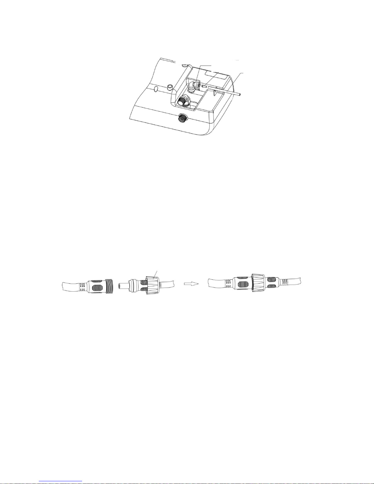
This product is factory-equipped with a drain pipe. If the drain pipe needs to be
extended because the water pipe is farther or for other reasons, please use the
1/4" quick connector. Pay attention to the flow control connector. The drain hose
is correctly installed when connected as shown in figure 22. Please contact your
distributor if you lose it.
Back pipe
Reserved outlet
Cut-off filter valve
Connection to cold
Connection to water heater
Cold water connection to mixing water
valve
Water outlet to unit
Water inlet to unit
Main water inlet
Page 21
SHOWER SOFTENER-CEASA 21
Figure 22
3.3.4. Power Wire Installation
This product needs the power supply to be located far away from water mist
when the device is installed. The power plug uses a seal design. For installation,
please tighten the power wire connector nut as shown in figure 23.
Figure 23
Quick connector
Flow control
Drain pipe
Power wire connector nut
Page 22
22 SHOWER SOFTENER-CEASA
1. Power on, slowly open the water supply, let the device switch to the service
position, wait about five minutes and check for leaks in the connection pipe. If
there are leaks, please tighten the leakage area.
2. The first time the device is operated, there may be a little yellow water coming
from the outlet. This is a normal phenomenon that occurs because the resin is
new and should disappear after rinsing.
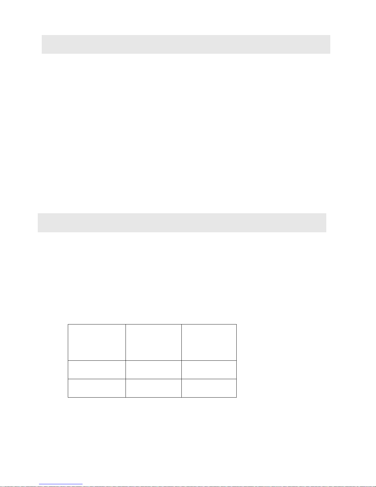
5.1. Water Capacity
Water capacity is related to water hardness. Bathing water consumption is calculated
based on 40 L per day for a family of three.
Water hardness
Water capacity
Time until
regeneration
200mg/L
750L
About 6 days
400 mg/L
320L
About 3 days
The user can make calculations based on actual water use if the water hardness is
450mg/L.
4. TRIAL RUN
5. REGENERATION OPERATION
Page 23

SHOWER SOFTENER-CEASA 23
During operation, the product will show the days of use as 01 (used for one day after
regeneration), 02 (used for two days after regeneration), for easy verification of the
days of use.
In order to correctly control the time until regeneration, please set the detailed
parameter as per the following pages. The user can set the number of days for the
regeneration reminder according to use requirements.
5.2. Regeneration Salt Consumption
Salt consumption during regeneration depends on the characteristics of the residential
softener. One regeneration needs 400g of salt. Reminder: Using other salts may have
adverse effects.
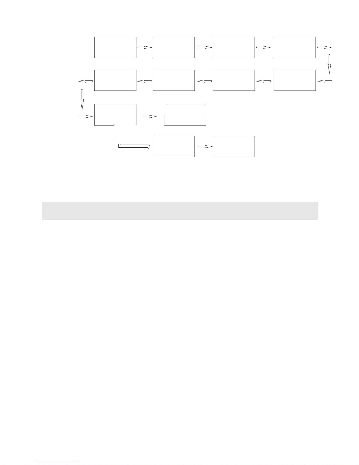
5.3. Regeneration Process
When water capacity reaches a certain value, resin fails and regeneration salt needs to
be used for regeneration. Method:
1.1 The unit needs water supply for the regeneration. The user needs to open
the water mixing valve if installed after the water heater and let cold water
enter the unit; otherwise the regeneration will be invalid.
1.2 To carry out the regeneration, press for 3 seconds until you hear a
beep. The device enters the regeneration mode, the motor rotates, the
display screen shows , when backwash is reached, the display screen
shows and water comes out of the drain; it remains in state for 30
Page 24
24 SHOWER SOFTENER-CEASA
seconds and automatically switches to , then flashes and a buzzer
sounds.
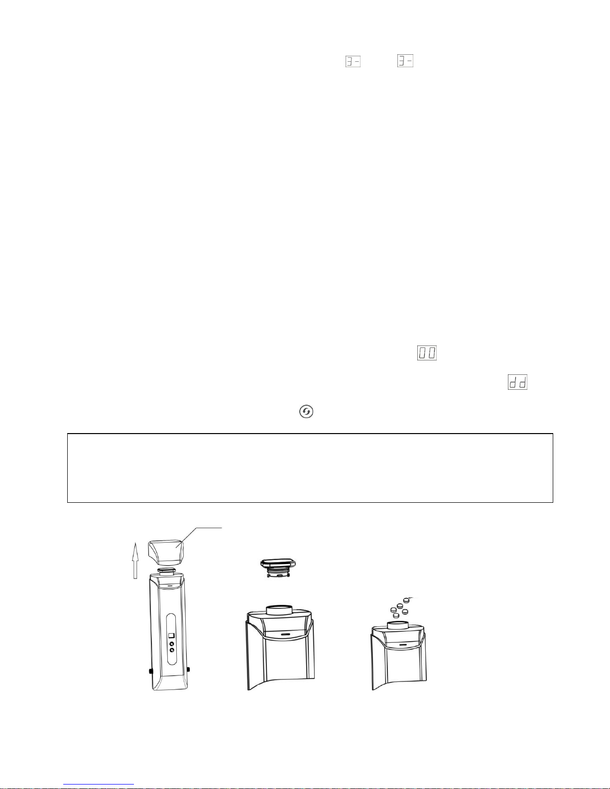
1.3 Open the upper cover of the housing as shown in figure 24. Then,
unscrew the cover as shown in figure 25 and add 400 g of special
regeneration salt as shown in figure 26. Stir salt particles to evenly
distribute them inside the salt tank, tighten the cover and close the upper
cover. Adding salt should take less than 3 minutes.
1.4 The system will automatically flush itself after the regeneration. The
process takes about 1h and doesn’t need to be supervised. After the
regeneration is completed, if the program selected is the front installation
mode, the system will switch to the water supply ; if the back-end
installation mode is selected, the system will go into standby mode .
The user will need to press the switch to select the water supply state.
Figure 24 Figure25 Figure 26
Note: After regeneration, there could be a small amount of water in the switching
station outlet. Please make sure it doesn’t spill on the unit.
Remove the upper cover
Regeneration
salt
Page 25
SHOWER SOFTENER-CEASA 25
Regeneration flow chart
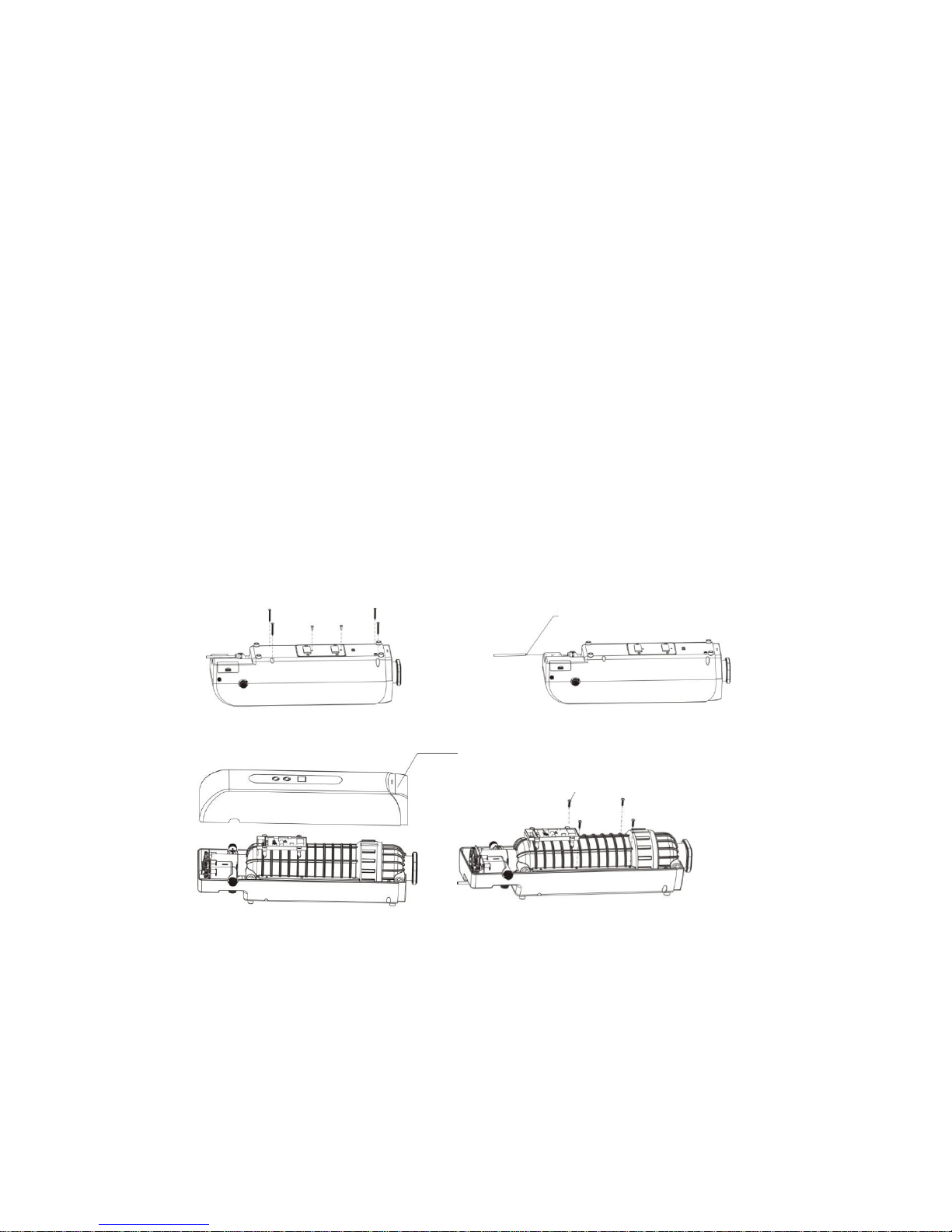
When the device has been used for two to four years, resin needs to be replaced.
Please rely on a qualified professional to change the resin. If you wish to change
the resin yourself, please follow the steps below.
a. Screw out the 4 screws on the back cover and the 2 screws on the side with
a cross-head screwdriver.
b. Take out the drain hose from the quick connector. Please pay attention to
the drain line flow control; put it down carefully to avoid losing it.
c. Take out the front cover from the unit, and handle with care to avoid
causing damage.
d. Using a cross-head screwdriver, screw out the 4 screws that fix the resin
tank to the back cover.
One key to start
Wait for the
Remove the
upper cover
Unscrew the salt
tank cover
System in
regeneration
Place the cover
Tighten the
salt tank cover
Add in
regeneration salt
Wait about 1h
after regeneration
Front installation
mode
Enter into water
supply state
Back-end
installation mode
Enter into
standby state
Manually switch
to water supply
6. RESIN REPLACEMENT
Page 26
26 SHOWER SOFTENER-CEASA
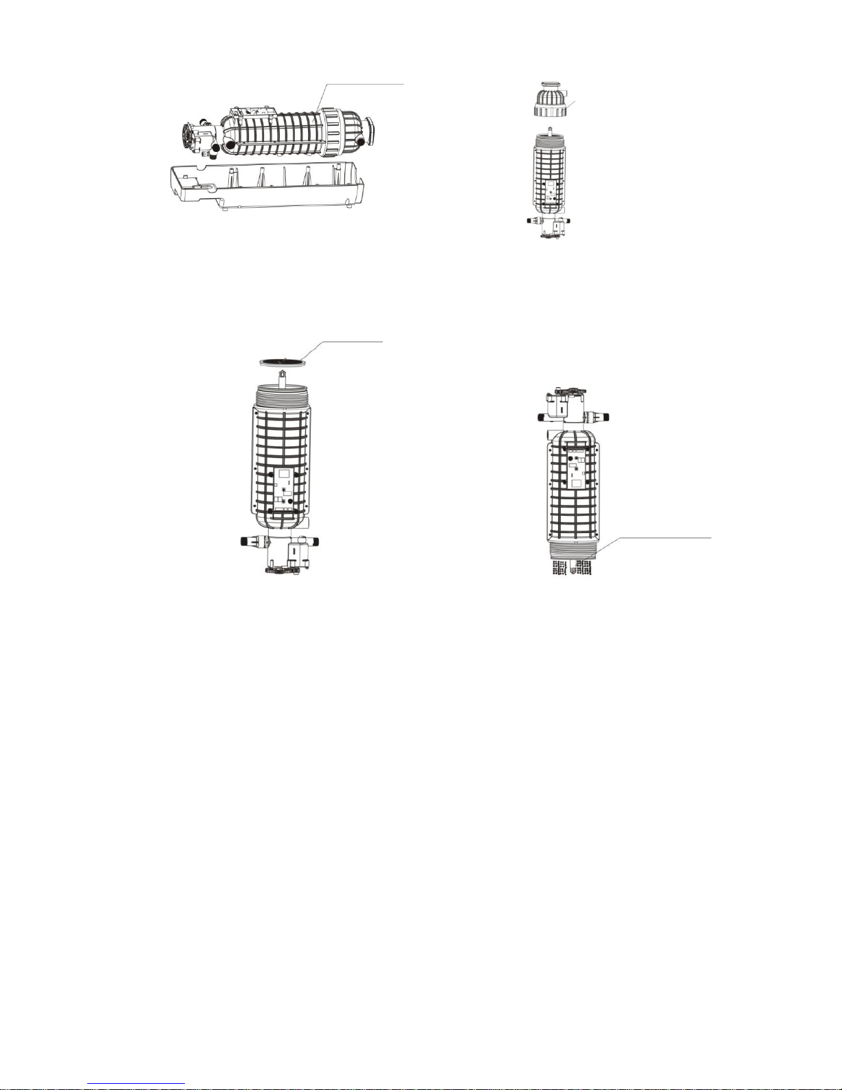
e. Take out the resin tank and valve assembly. Handle with care to avoid
damaging the circuit.
f. Screw out the resin tank cover with special tools.
g. Take out the strainer carefully to prevent the riser pipe from dropping out.
h. Press the riser pipe to prevent it from dropping out. Pour out the resin, and
add 2.5L of new resin to the resin tank.
i. Install the shower softener according to the above steps, noting the
following during the installation process:
1. The tread on the resin tank and the O-ring should be clean
2. If the riser pipe drops out, it needs to be cleaned before placing it inside the resin
tank.
3. Please make sure the drain line flow control is intact when installing the drain pipe.
d. Take out back cover screw
Take out 6 screws with a screwdriver
c. Remove drain pipe
Drain line flow control
Front cover
b. Remove front cover
a. Remove resin tank screw
4 screws
Page 27
SHOWER SOFTENER-CEASA 27
Press the riser pipe
and pour resin
f. Take out resin tank assembly
Take out resin tank and valve assembly
e. Unscrew resin tank cover
Resin tank cover
g. Take out top strainer
Top strainer
h. Pour resin
Page 28
28 SHOWER SOFTENER-CEASA
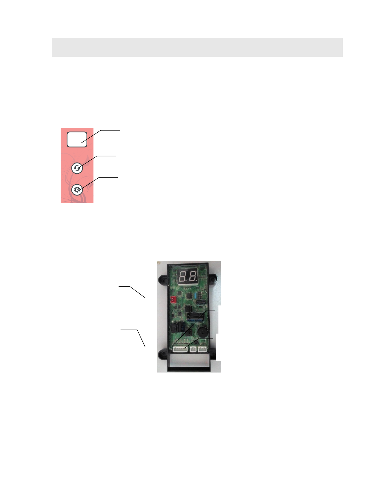
7.1. Product Control Panel Overview
7.2. Main Board Socket Overview
Sockets on the main board are one-to-one. Follow the color and number of pins
to insert.
Regeneration/confirm button
Display area
Set button
Power socket
Locating board
socket
Flow meter socket
Motor socket
7. PARAMETER SETTING
Page 29
SHOWER SOFTENER-CEASA 29
7.3. Product Installation Mode Setting
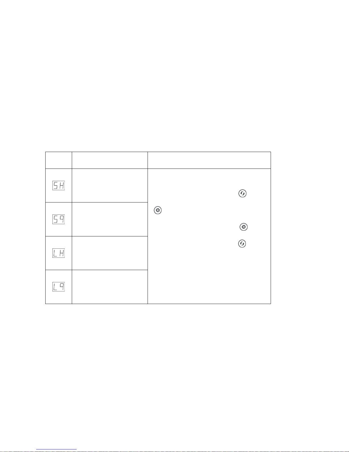
This product uses a different program depending on whether it is installed before or
after the water heater. Also, resin failure reminders are divided into time type and
meter type (this softener is only suitable for time type; meter type will be available
in the future).
Below is the meaning of each code
Code
Meaning
Setting
Installed after water
heater, time type
Power on again, press both and
for three seconds, then enter into
the installation mode, press to
select the mode, then press to
save and quit.
Installed before water
heater, time type
Installed after water
heater, meter type
Installed before water
heater, meter type
Inquire mode: Power on again, and the interface will display the installation mode.
Page 30
30 SHOWER SOFTENER-CEASA
7.4. Regeneration Reminder Day Setting
Time type
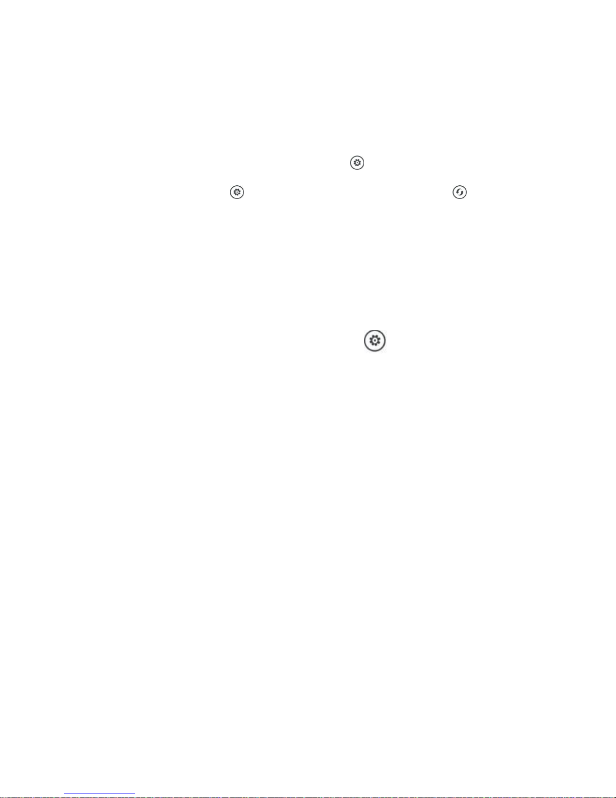
An alarm can be set in the softener according to actual use conditions. The screen
flashes to remind users to add salt. Press and hold for time type, enter the number
of days setting, then press , set the days for the reminder, press to save and
quit. If set to 07, the display will flash to remind the user to add salt 7 days after the
regeneration. Factory default is 00: no reminder.
Meter type
To adjust the water hardness, press and hold the button in the service
position.
This will enter the settings menu, where you can adjust the number from 5 to 50.
5 equals 50 ppm, 6 equals 60 ppm, and 50 means 500 ppm. Based on this information,
you can adjust the water hardness, and the system will calculate the water treatment
capacity automatically.
When the shower softener is operational, the LED display shows a value like
“1111” to indicate how much of the treated water has been used. For example, when
the softener starts to operate, it will show “1111” at first. After operating for a few
days, it may only show “111”, then after a while, it will show “11”, then “1”. When
the treated water is used up (the water capacity is reached), the “1” will flash to
remind you to start the regeneration.
Page 31
SHOWER SOFTENER-CEASA 31
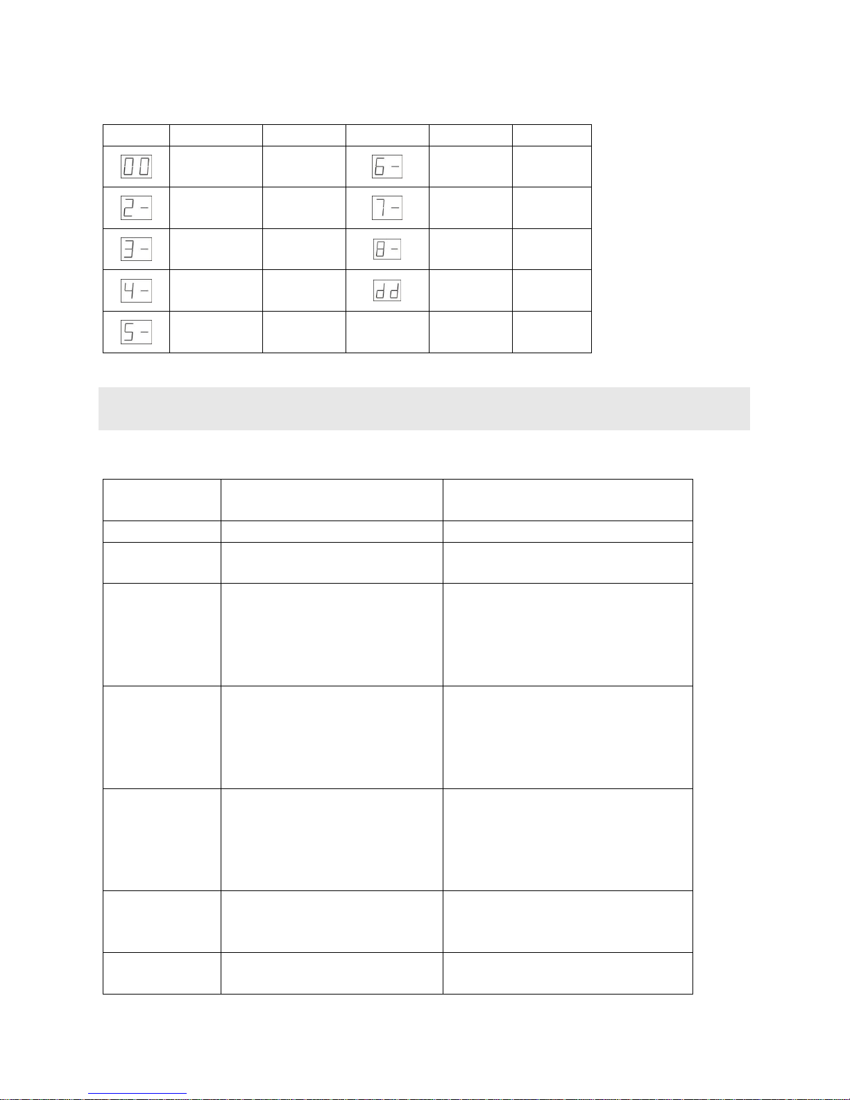
7.5. Meaning of Operation Codes
Code
Meaning
Explanation
Code
Meaning
Explanation
Service/
Service days
Fast rinse
Drain water
out
Backwash
Drain water
out
Salt
dissolved
Salt dissolved
Fast rinse
Drain water
out
Fast rinse
Drain water
out
Waiting to
be closed
Salt dissolved
Problem
Cause
Correction
Leakage
O-ring missing or not tightened
Install O-ring and screw tight
Water flow rate
decrease
Strainer blocked
Clean strainer and install front filter
Water quality is
unsatisfactory
1. Invalid resin
2. Resin has exceeded its
service life
3. Unsuccessful regeneration
1. Regenerate resin
2. Replace with new resin
3. Check if the drain line is blocked
or use the special regeneration
salt
Unsuccessful
regeneration
1. Special regeneration salt was
not used
2. The drain is blocked
3. Water inlet wasn’t open
during regeneration
1. Use the special regeneration salt
2. Open up the drain line flow
control
3. Open the water inlet and
perform regeneration again.
E1 flashes
1. Motor damaged
2. Control board failure
3. Locating board failure
4.Moving disc stuck
1. Replace motor
2. Replace control board
3. Replace locating board
4. Clean moving disc and fixed disc
E2 flashes
1. Wiring of locating board is
faulty
2. Control board failure
1. Replace locating board wiring
2. Replace control board
E3 flashes
Control board failure
1. Replace control board
8. TROUBLESHOOTING
Page 32
32 SHOWER SOFTENER-CEASA
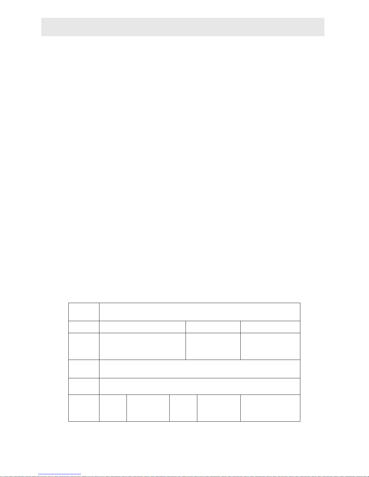
Dear client,
This warranty card is the proof of warranty of the CEASA Shower Softener. The
client is responsible for keeping it. It allows you to request after-sales services from
the supplier appointed by the manufacturer CEASA. Please store it properly. If lost, it
cannot be replaced. Free repair services cannot be requested under the below
conditions:
1. Warranty period expired (one year);
2. Damage resulting from use, maintenance and upkeep not in accordance with the
instructions;
3. Damage resulting from repairs carried out by unauthorized maintenance
personnel;
4. The contents of the proof of warranty cannot be verified with the label or have
been altered;
5. Damage caused by force majeure.
Product
Name
RUNLUCKY SHOWER SOFTENER
Model
Code of Valve Body
Purchase
Company
Name
Tel/Cel.
Problem
Solution
Date of
Repair
Date of
Completion
Maintenance
Technician
Signature
9. WARRANTY CARD
Page 33

SHOWER SOFTENER-CEASA 33
COMPAÑÍA EUROPA DEL AGUA, S.A.
ADDRESS: C/R.F. Alemania 21-25, Polígono Industrial Rosanes
Castellví de Rosanes, Barcelona Postal code: 08769
TEL.: (00 34) 937 766 344 FAX: (00 34) 937 766 344
WEB: http://www.ceasaespana.com E-mail: [email protected]
 Loading...