

Page 1
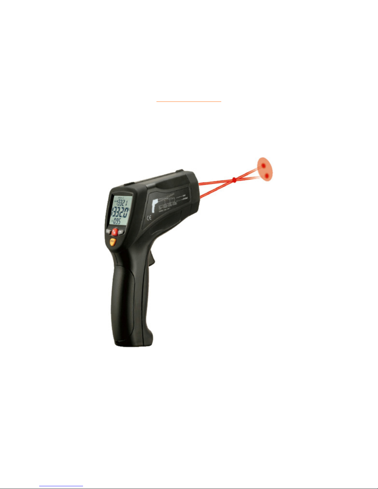
IF324
IF300 - 2008 Series
Combo Digital Thermometer
For measurement No-contact & with Thermocouple Type K
IR Range -50.0 ÷ 1600.0 °C - Range T/C Tipo (K) -50.0 ÷ 1370 °C
With a double Laser Pointer – USB Gate – Software Ms. Windows
Art. 5A808
Operating Manual
Cod. IF324_5A808_UK_M1
English Language
Product Rev: 1.0 - Manual Rev: 1.2
Page 2

IF324_5A808_UK_M1
® Copyright CEAM Group
CEAM Control Equipment
2
Page 3

IF324_5A808_UK_M1
® Copyright CEAM Group
CEAM Control Equipment
3
General Index:
1 – Before Beginning
2 – Technical Specifications
2.1 – General Characteristics
2.2 – Range – Resolution – Precision @ Measure with Thermocouple
2.3 – Range – Resolution – Precision @ Measure without contact Infrared
3 – General Instrument Legend
4 – Display Description
5 – Keyboard
5.1 – Instrument General Functions
5.2 – MODE Key Functionality
5.3 – LOG Functionality (Data Logger)
6 – Measurement Procedure
6.1 – Instrument Switching On
6.2 – Warning SCAN Measurement Activated
6.3 – Warning HOLD Measurement NOT Activated
6.4 – Automatic Switching Off Function (Power Saving)
6.5 – Important Consideration about the Measures
7 – Battery Changing
7.1 - Indication Low-Battery
7.2 – Battery place Opening
8 – Operative Notes & Emissivity Coefficient Table
9 – Maintenance
10 – Software
11 – Codes to order Accessories & Spare Parts
12 – Warranty Terms
Page 4

IF324_5A808_UK_M1
® Copyright CEAM Group
CEAM Control Equipment
4
Page 5

IF324_5A808_UK_M1
® Copyright CEAM Group
CEAM Control Equipment
5
Page 6

IF324_5A808_UK_M1
® Copyright CEAM Group
CEAM Control Equipment
6
1 – Before Beginning
Before Using the product, we suggest to read carefully this manual, moreover once you learned to use the instrument we
suggest always to make some test to familiarize with its functions, and only after being mastery of its use going on with the
real using.
For more information please contact the CEAM customer service
RECURRENT TECHNICAL TERMS GLOSSARY:
Term Meaning Abbreviation or Example
Target
With this term it is identified the point
of the measurement, that is the body,
the product or the point we intent to
make the measurement.
Spot
This term indicates the area, circle of a
variable diameter, in function of the
distance, inside which the instrument
receives the instrument infrared
radiation, which allows to make the
measurement of the average
temperature
Attention the shape of the Spot is
circular when the instrument is
positioned vertical on the Target, but in
case the instrument would be
positioned oblique, the Spot shape will
be elliptical
Optical Ratio
The optical ratio indicated by two digit
divided by two points (12:1) indicates
the ratio between Distance of the
TARGET and Diameter of the SPOT
which the optical of which is provided
the instrument allows, it is very
important to have clear this concept to
be able to obtain always reliable
measurements, but over all really
representatives of the Target
Let’s do an example: with Optical Ratio
12:1, it means for instance that at the
Distance of 1200 mm the Spot will have
a diameter of 100 mm (Fig. 1), and at
the distance of 12 meters the spot will
have a diameter of 1 meter, of course
this ratio is true also for intermeddle or
superior measures to the mentioned
values.
Laser Pointer
The Laser ray is used only to simplify
the measurement pointing, allowing
identifying with precision the exact
point where the operator is making the
measurement, and it is not used at to
make the measurement, which uses
just the infrared radiation.
It is important to remind that the little
red point of a constant diameter
identifies simply and indicatively the
centre of the measure Spot, and it is
not the only point where the measure is
done, while the diameter of the spot is
variable in function of the distance as
above explained
Wavelength
Or
Spectrum Response
The Wavelength of an instrument is in
few words the frequency range inside
which the instrument obtains the
infrared radiation which later it
transforms in a temperature value
This kind of thermometer, obtains a
radiation of electromagnetic waves
exactly as the radio we listen in into the
car, where the variation of frequency
determines a different emitter radio to
be listen, the difference between the
radio and the thermometer is that this
last one instead of an antenna has got
an infrared sensor and that instead of
the music, it retransforms the received
energy by the sensor in a temperature
value, the wavelength determines the
range inside which the instrument is
operative. To be noticed that inside the
infrared range there are several
different range more restricted which
typically are indicated as plus or minus
right to specific application and to
define also the working temperature
level.
Page 7

IF324_5A808_UK_M1
® Copyright CEAM Group
CEAM Control Equipment
7
Instrument Specifical Technical Terms Glossary
Abbreviation Description
What it is for
ε
Emissivity Abbrev. (EMS)
It Identifies the Emissivity Value which must be correctly set up to be able to
make the infrared Temperature measurement (Ref. Par. 2.1.4)
MAX
Max Temp. Reached It Identifies the max reached value memorized during the measurements
MIN
Min Temp. Reached It Identifies the min reached value memorized during the measurements
DIF
Differential Temp.
It Identifies the differential obtained value memorized during the
measurements
AVG
Average Temp.
It Identifies the average obtained and memorized value during the
measurements
HAL
HIGH Alarm It Identifies the High set up alarm value
LAL
LOW Alarm It Identifies the Low set up alarm value
Summary of the General Precautions:
Attention: The Instrument is provided by a double Laser Class II @ 675 nm source
Use the maximum attention when the laser rays are lit on
Never point it directly to people or animal eyes
Keep particular attention not to pointing the laser ray on reflecting surfaces which could the ray
in an uncontrolled way
Never point the Laser ray on gas or inflammable and/or explosive liquids
You should never exceed the operative limits written on this manual, reminding also that a respectable using extend the
product’s life
The product is not hermetic and it cannot stand humidity, steams and liquids which could damage both the electronic and
the optical side.
Avoid letting have to the instrument quick temperature ranges which could generate condensate inside or even just on the
optical side.
Never clean the optical, mainly with systems and abrasive products, solvents, oily products, and everything could damage
or even just dirt or opacity it, the damage of the optical makes the product unusable, in case it get dirty, it is possible to try a
light cleaning using water base products, that you can find in some seller of optical and photo equipments.
Attention: each cleaning operation is at total risk of the customer.
Do not try to open the product, opening it, warranty will be immediately void
Never use spare parts or accessories not original or certified by CEAM
Attention: regarding the Batteries, being consumable material, we remind that they are not included in the warranty
covering, and that each intervention and/or substitution is on charge of the customer.
Page 8

IF324_5A808_UK_M1
® Copyright CEAM Group
CEAM Control Equipment
8
2 – Technical Specifications
2.1 – General Characteristics:
- Combo Thermometer for Measurements without any contact (Infrared) & With Thermocouple (Type K)
General Characteristics Common to the two Measurement Technologies:
- Back enlightened Display
- Measure Unity °C & °F to be set up
- Automatic Selection of the Measure Range
- Automatic Selection of the Visualized Decimal
- Visualization of the Minimum – Maximum Temperature (MIN – MAX)
- Average (AVG) and Differential (DIFF) Temperature Calculation
- Setting up of the High and Low Temperature Alarms
- Function Data hold which allows freezing the Measure at the release of the Trigger
- Energy save Function with Automatic Power OFF
- Operative Conditions: 0 ÷ 50 °C (32 ÷ 122 °F) - 10 ÷ 90 %UR
- Stocking Conditions: -10 ÷ 60 °C (14 ÷ 140 °F) – 5 ÷ 80 %UR
- Power Supply: Battery 9V – NEDA 1604A – IEC 6RL61 or Equivalent
Characteristics Measures without Contact (Infrared):
- Infrared Measure Range -50…1600 °C (-58.0 ÷ 2912 °F)
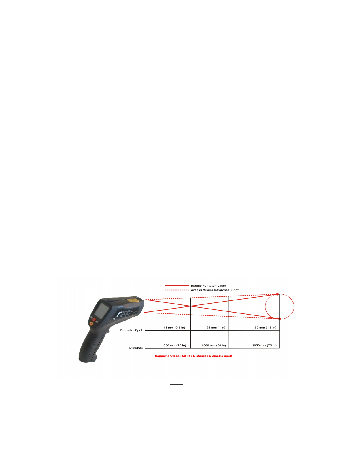
- Optical Ratio 50:1 (to the Distance of 50 cm it has a Spot Diameter 1 cm)
- Accuracy: Look at Table Ref. Par. 2.3
- Wave Length 8 ÷ 14 µm
- Configurable Emissivity within 0.10 ÷ 1.0
- Response Time: 150 ms
- Provided by a Double Laser Pointer to localize approximately the position of the Measure Spot
- Laser Type: No. 2 Diodes < 1 mW – Wave Length 630 ÷ 670 nm – Class II (2) Laser Product
Characteristics Measures with Thermocouple:
- Compatible Thermocouple: Type K
- Connection: Male Mignon Connector
- Infrared Measure Range -50…1370 °C (-58.0 ÷ 2498 °F)
- Accuracy: Look at Table Ref. Par. 2.3
Page 9
IF324_5A808_UK_M1
® Copyright CEAM Group
CEAM Control Equipment
9
2.1.1 – Application Fields:
The instrument for its characteristics is very flexible and easy to be used, then it is proper for a general use and we indicate
some typical application:
- Industrial Sector
- Food Sector
- Seasoning
- Painting
- Security and Firing prevention Sector
- Plastic moulding and plastic materials working
- Asphalt Working in Covering & Street Applications
- Typographic and Packaging Sector
- Food Cooking and Drying
- Service Sector
- Electric Installation and Servicing
- Building Sector
- Insulating Materials Installation and processing
2.1.3 – Optical Ratio (Optical Vision Field @ of the Infrared measure):
F324 is a combo thermometer, which serves then to measure the temperature, but differently form other kind of
thermometers, this kind of instrument thanks to its technology succeed in making the measurement both in a traditional way
with a thermocouple and without physical contact with the product to be measured, this is possible thanks to the particular
used technology, which is based on the survey of the infrared radiation inside a specifically frequency range, also called
wavelength, which all bodies plus or minus emit in function of their nature and of the temperature they are.
The instrument “catches” these radiations, invisibles to the human eye, through a special electronic sensor, and thanks to a
powerful circuit provided by a micro-processor, able to make complex calculations, it converts the radiations in a precise
temperature measure.
Then as it should be clear, the instrument act itself as an optical “Passive” device, with a result that the major will be the
distance between the instrument and the Target (Target = Point of Measure) and major will be the dimension of the SPOT
and vice versa, as explained in the below graphic example.
Attention: the two laser rays visible during the measurement are only the pointer which makes easier the estimate
individuation of the point and of the measurement area, they don’t have any function in the measurement, it is very important
keeping in mind this detail, because it can be to find a case in which making for instance a measurement through a glass, the
laser will pass through it, letting you think the measurement is through the glass, while in reality the infrared measurement
will be on the surface of the glass, this detail is explained by the fact that on the operative Laser frequency, the glass is
transparent, while on the thermometer infrared wave length the glass is absolutely opaque, that means impenetrable.
Fig.1
2.1.4 - Emissivity:
The correct conversion of the infrared radiation in a temperature value is made by mathematical formula (Law of PLANCK)
which for a correct conversion, asks the set up of a constant called “Emissivity” which changes in function of the kind of
material we are going to measure, the emissivity of the instrument described in this manual, is changeable from 0.10 up to a
1.00
For further details please read the specific next chapters
Page 10
IF324_5A808_UK_M1
® Copyright CEAM Group
CEAM Control Equipment
10
2.2 – Range – Resolution – Precision @ Thermocouple Measurement:
Table: Range & Precision for the Measurements with the Thermocouple
Range °C Range °F Precision Repeatability Display Resolution
-50 ÷ 1000 -58 ÷ 1832 ± 1.5 % of the reading ± 3°C ( ± 5 °F) ± 1.5 % of the reading 0,1
1000 ÷ 1370 1832 ÷ 2498 ± 1.5% of the reading ± 2°C (± 3.6 °F) ± 1.5 % of the reading 1
Rif. Conditions @ Environmental Temp. 23 ÷ 25 °C (-73 ÷ 77 °F)
2.3 – Range – Resolution - Precision @ Measurement without contact, with infrared:
Table: Range & Precision for the Measurements without Contact with Infrared
Range °C Range °F Precision Repeatability Display Resolution
-50 ÷ 20 -58 ÷ 68 ± 2.5 °C ( 4.5 F) ± 1.3 °C (2.3 °F)
0,1 @ < 1000
1 @ > 1000
20 ÷ 400 68 ÷ 752 ± 1.0% ± 1.0 °C (1.8 °F)
± 0.8% ±0,5 °C (0.9 °F) 400 ÷ 800 752 ÷ 1472 ± 1.5% ± 2.0 °C (3.6 °F)
800 ÷ 1200 1472 ÷ 2912 ± 2.5%
1200 ÷ 1600 1472 ÷ 2912 ± 2.5% ± 1.2% ±1,0 °C (1.8 °F)
Rif. Conditions @ Environmental Temp. 23 ÷ 25 °C (-73 ÷ 77 °F)
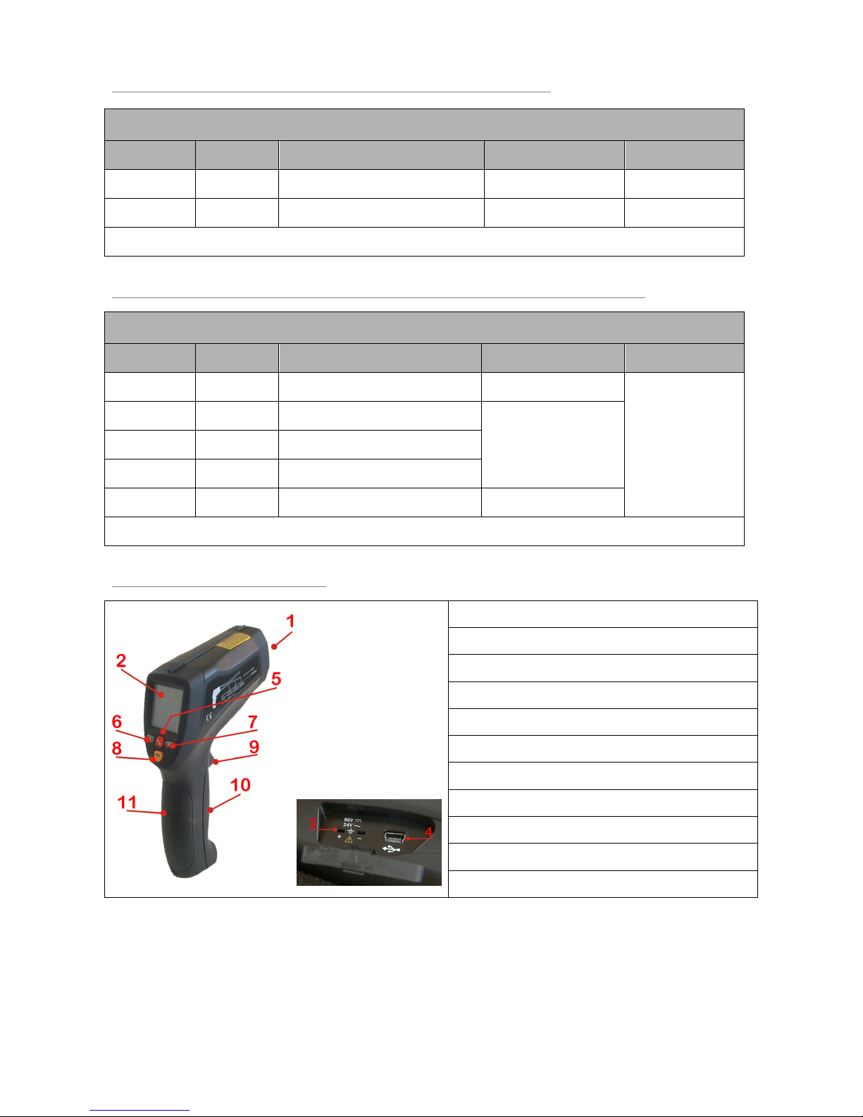
3 – Instrument General Key:
1) Optics & Infrared Sensor (Detector)
2) Display LCD
3) Type “K” Thermocouple Input (Left side of Instrument)
4) USB Gate (Left side of Instrument )
5) Backlighting Display & Laser Managing Key
6) UP Key
7) DOWN Key
8) MODE Key
9) Measurement Trigger
10) Battery Room Cover
11) Handle Grip
Page 11
IF324_5A808_UK_M1
® Copyright CEAM Group
CEAM Control Equipment
11
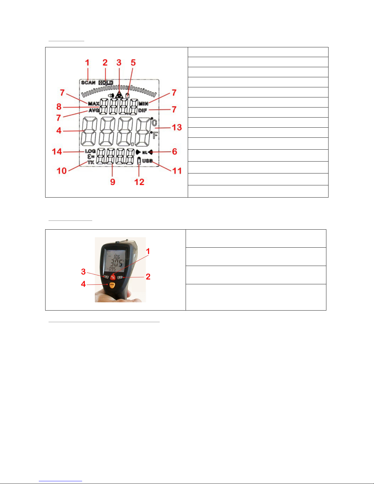
4 – Display
1) Indicator of the Present Measurement
2) Data Hold Indicator
3) Laser ON
4) Indicator of the measured Temperature
5) Lock Abbreviation
6) High Alarm and Low Alarm Abbreviation
7) Symbols MAX – MIN – AVG – DIF
8) Indicator of the Temperature MAX – MIX – AVG - DIF
9) Indicator of Value Emissivity Or Temp. T/C
10) Indicator Abbreviation Emissivity Or T/C
11) USB Abbreviat. (Active gate to transmit data to the PC)
12) Low Power Indicator
13) Indicator °C / °F
14) Data Logger Function Abbreviation
5 – Keyboard
1) Key On-Off Backlighting & Laser
2) Key UP (EMS – HAL – LAL)
3) key DOWN (EMS – HAL – LAL)
4) Key MODE – Rotation Instrument Functions and Display
5.1 – Instrument General Functionalities
5.1.0
– Preamble, The instrument can be activated in the following modalities:
MEASURE: This modality is activated simply pressing the trigger (Ref. Cap. 3 – Pos.9), during this period the
instrument visualize on the display the word SCAN (Ref. Cap. 4 – Pos.1), for short this period would be
denominated MEASURE
HOLD: This mode activates itself automatically, when you release the trigger (Ref. Chap.3- Pos.9) after the
measurement, and if you don’t press any key during this time, and you did not disable the energy save
function, the instrument automatically turns off after few seconds, during this phase the instrument visualize
its state through the word HOLD on the display (Ref. Chap.4 – Pos. 2), for short, this phase can also be called
HOLD
5.1.1
– During the MEASURE, pressing again and again the key MODE (Ref. Chap.3 - Pos.8) you visualize in
sequence the values got respectively: MAX (Maximum), MIN (Minimum), DIF (Differential), AVG (Average), LOG.
5.1.2
– During the Infrared MEASURE (Without Inserted Thermocouple), it is possible to adjust the value of
Emissivity, pressing the arrow keys UP – DOWN (Chap.5 – Pos. 2 & 3); the modified value is visualized on the
display (Ref. Chap.4 – Pos.9)
5.1.3
- When in OLD, you can select the temperature display in °C or °F pressing the keys UP & DOWN (Ref.
Chap.5 – Pos.2 &3)
Page 12

IF324_5A808_UK_M1
® Copyright CEAM Group
CEAM Control Equipment
12
5.1.4
– To switch on or off the backlight of the Display or the Laser Pointer, both in MEASURE and in HOLD
press again and again the central red key (Ref. Chap. 5 – Pos. 1)
The activation of the backlight is highlighted by the backlight itself, while the activation or the deactivation of
the Laser pointers is marked by the visualization of the abbreviation LASER on the display (Ref. Chap.4 –
Pos.3) the visualized indication means pointer ON.
5.1.5
– To be able to set the value HAL (High Alarm) LAL (Low Alarm) and ε (EMS =Emissivity) press again and
again the key MODE (Ref. Chap.5 – Pos. 4) until on the display it appears the desired symbol (Ref. Chap. 4 – Pos. 6 &
9), once you select the symbol of the parameter you want to set, proceed through the keys UP & DOWN (Ref. Chap.5 –
Pos.2 & 3)
5.2 – Functionality MODE key
During the modality HOLD, press the key MODE again and again, to enter in a sequential way to the
visualization of the following data logged and/or calculated during the measurements:
LOG
MAX = Maximum Visualization reached during the measurement
MIN = Minimum Visualization reached during the measurement
DIF = the Thermal difference between MAX & MIN reached during the measurement
AVG = the average temperature reached during the measurement
Note: To scroll the above parameters, press the keys UP & DOWN (Ref. Chap.5 - Pos.2 & 3)
Continuing
And to the configuration of the parameters in sequence:
ε
EMS = Emissivity Set for the infrared measurement
LOCK On-Off = Activation / Deactivation Keyboard Lock
H (HAL On-Off) = Activation / Deactivation High temperature Sound Alarm
H (HAL Set Point) = Value Set Set-Point High temperature Alarm
L (LAL On-Off) = Activation / Deactivation Low temperature Sound Alarm
L (LAL Set Point) = Set Visualization Temperature °C/°F
Note: To Scroll the vales to be set press repeatedly the key MODE, to set up the values, use the keys UP &
DOWN
5.3 – Functionality LOG (Data Logger)
5.3.1 – Memory Capacity
The thermometer IF324 is supplied by 100 independent memory areas, where logging the data of the
temperature to be taken.
Note: for each area it is possible to log a single temperature value, if we log several values on the same
memory cell, the value logged will always be the last one.
5.3.2 – Storage Measurement IF (Infrared) Data
To store these data proceed as follows:
In MEASURE, then with the trigger pressed, press repeatedly the key MODE, until the abbreviation LOG will
appear on the (Ref. Chap.4 – Pos.14)
Select the storage area where we desire to store the data; using the keys UP & DOWN always in condition of
MEASURE, the selected area, from 0 up to 100, will be visualized on the display (Ref. Chap. 4 – Pos. 8)
Once selected the memory cell, you can proceed to store the desired value, pressing the red key of the
Backlighting/Laser (Ref. Chap. 5 – Pos. 1), the stored value will be visualized on the display in little on the low
side (Ref.Chap.4 – Pos.9)
Page 13

IF324_5A808_UK_M1
® Copyright CEAM Group
CEAM Control Equipment
13
5.3.3 – Re-Reading Stored Data in LOG - Measure IF (Infrared)
To read again these data proceed as follows:
Keeping pressed the measurement trigger (Ref. Chap.3 – Pos.9), press repeatedly the key MODE until on the
display it appears the abbreviation LOG (Ref. Chap.4 – Pos. 14), at this point release the trigger, and operating
on the keys UP & DOWN, it is possible to scroll the several memory positions, visualizing them from 1 to 100
on the display in little on the high side (Ref.Chap.4 – Pos.8) , the stored temperature corresponding to the
memory cell is visualized on the display in little on the low side (Ref. Chap.4 – Pos.9)
Note: Not touching anymore any key for at least 7 seconds the instrument switch itself off
5.3.4 – Erasing of the LOG Storage
This function allows to erase quickly all the stored data in the LOG, and to proceed execute the following
procedure:
The erasing can be made only when the instrument is in LOG, this state is confirmed by the visualization of the
abbreviation on the (Ref. Chap. 4 – Pos. 14), if the display does not visualize this abbreviation, always in
MEASURE, with pressed trigger, press repeatedly the key MODE (Ref.Chap.5 – Pos.4) until it appears the
abbreviation LOG.
Once assured to be in LOG, always keeping pressed the trigger, pressing repeatedly the key DOWN up to
arriving in visualizing the memory cell 0, visualized on the display little in the high side (Ref.Chap. 4 – Pos.8),
without releasing the trigger, press shortly the red key Backlighting/Laser (Ref. Chap.5 – Pos.1), the
instrument will confirm the erasing with a double sound note, and the display will visualize the memory cell 1,
ready to begin a new storage
5.3.5 – Activation –Deactivation USB Gate to download data
The instrument is supplied by a digital communication USB gate, through which it is possible to download the
stored data to visualize them on the PC.
Activation USB Gate
: To activate it, it is necessary that the instrument is in the state MAX-MIN-DIF-AVG, with
one of these abbreviations visualized on the display (Ref. Chap.4 – Pos.7), then keep pressed for few seconds
the red key Backlighting-Laser (Ref. Chap.5 – Pos.1) until the abbreviation USB appears in the low right corner
of the display (Ref. Chap.4 – Pos.11).
Deactivation USB gate
: To deactivate the function, it is necessary that the instrument is in the state MAX-MIN-
DIF-AVG, with one of these abbreviations visualized on the display (Ref. Chap.4 – Pos.7), then keep pressed for
few seconds the red key Backlighting-Laser (Ref. Chap.5 – Pos.1) until the abbreviation USB disappears from
the low right corner of the display (Ref. Chap.4 – Pos.11).
Page 14
IF324_5A808_UK_M1
® Copyright CEAM Group
CEAM Control Equipment
14
6 – Measurement Procedure
6.1 – Switching on the Instrument
The instrument will switch on automatically, simply pressing the measurement trigger (Ref. Chap.3 – Pos.9).
Note: Be sure the instrument has got its battery and that the battery is charge
6.2 – Light SCAN Measurement Active
The instrument advice the measurement active, visualizing on the display the abbreviation SCAN (Ref. Chap.4
– Pos.1), typically with pressed trigger.
6.3 – Light HOLD Measurement not Active
The instrument, through the abbreviation HOLD (Ref.Chap.4 – Pos.2) advice that the measurement is not
active and it is visualizing the last measured value, this condition comes releasing the measurement trigger.
6.4 – Automatic Switching Off (Power Saving)
The instrument switches off automatically if the trigger is released and any other key is pressed in 7 seconds.
Attention!!!
6.5 – Important Considerations for the Measurements
A) keep always well pointed the instrument on the body to be measured, keeping attention that the product and/or the
material to be measured was compatible with the instrument, and over all that the distance of the TARGET is such that the
SPOT should be completely covered, in fact we remind that in case of partial covering, the instrument make anyway the
measurement making a thermal average of the surface, in case even one single part of the SPOT would be with a different
temperature and outside the body to be measured, the result would be in proportion distorted.
B) the measurement infrared sensor needs the environmental temperature compensation, which the instrument makes
automatically, but to obtain reliable measurements it is necessary to allow to the instrument to adapt itself thermally to the
environment where it is, especially if before it was in a place with different temperature, in this case it is necessary to place
the instrument where we intend to make the measurement, and wait at least 30 minutes for its stabilization, and only after
that going on with the measurement.
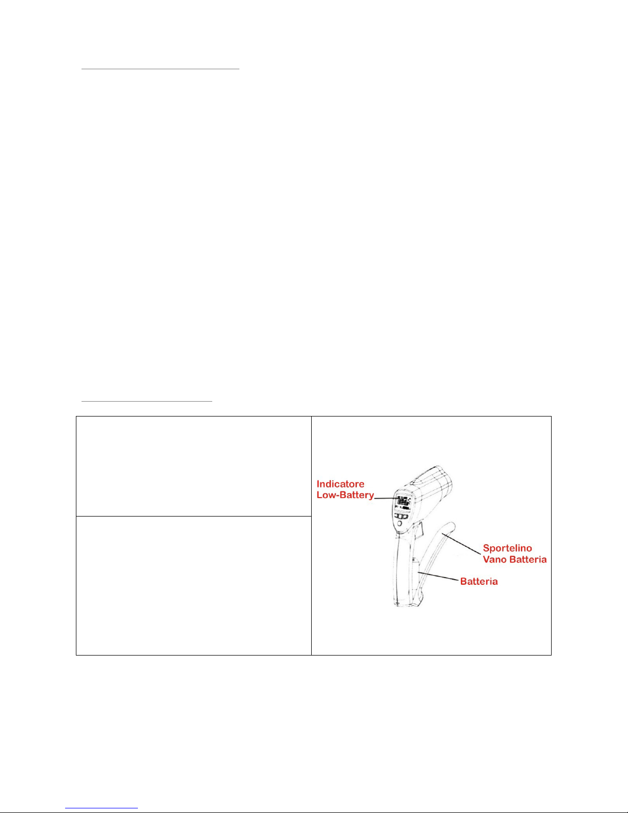
7 – Battery Substitution
7.1 – When on the display will appear the abbreviation (Low
Battery) it means that the battery is flat (Chap.4 – Point 12)
since this moment the measurements are not reliable
anymore even if the instrument go on working, and it is
necessary to change it with a new one, or load them again if
the instrument is furnished by the optional rechargeable
battery.
7.2 – Open the cover of the battery room making it roll
ahaead, as indicated by the picture on the side (Chap. 3 Ref. 10), take out the flat battery, putting in the new one
making attention to connect the right polarity.
Attention: After having taken out the old battery, check always that the room is clean, and that there are no
trail of acid from the old battery, in case you can see even little traces of acid, remove them immediately with a
dry brush and send the instrument in repair to CEAM service to avoid that the acid contamination would
corrode also the circuit making the instrument useless.
Page 15
IF324_5A808_UK_M1
® Copyright CEAM Group
CEAM Control Equipment
15
8 – Operative Notes
HOW IT WORKS: As already explained in the previous chapters, the instrument measures the temperature
through the conversion in a temperature value, of the infrared radiation taken, inside a specific frequency
gamma or wave length, which is taken by the Optical infrared Detector, which works exactly as an antenna.
This energy is directed in the centre of the optical “Focus” of the detector thanks to special transparent lens to
the radiation, in function of which it is determined the optical ratio of the instrument, that is the dimension (the
diameter) of the spot at a definite distance.
THE SIGHT FIELD: The infrared energy taken, is directed to the centre of the optical “Focus” of the detector
thanks to special transparent lens at the radiation wave-length, the optical dimensioning of the lens
determines the optical ratio of the instrument, that is the ratio between the dimension (the diameter) of the
SPOT that you obtain at a definite distance between the instrument and the TARGET, as already largely
explained in the previous chapters , it is very important that the dimension of the SPOT must be largely smaller
then the TARGET surface to be measured, in a different case you would obtain measurement errors in function
of the thermal proportion in function of the area.
Besides on the bases of the optical Ratio it is important to remind that bigger will be the distance between the
instrument and the TARGET and bigger will be the Dimension / Diameter of the SPOT , then smaller will be the
distance and smaller will be its Dimension / Diameter as showed clearly in Pict. 1 of Chapt. 2.
Attention: The SPOT is always defined as a round area, but this is data on theory and it is true only in case the
instrument is perfectly vertical on the TARGET and with this last one perfectly flat, on the contrary if the
instrument is in a inclined position, the shape of the SPOT will be elliptical, while if we are measuring irregular
bodies, the shape of the SPOT will assume irregular shapes as consequence.
IDEA: To have an idea of how it works, it is enough to use an electric torch which produces a light cone, which
besides its dimension (Optical Ratio) if you position it in a vertical way it will produce a round lighted area,
besides if you position it in a slanting way, the shape of the lighted area will be modified, and the same will
happen making different experiments.
LASER POINTER: to avoid any misunderstanding, we want to remind that the laser pointer, in this case,
double, does not represent the measured surface, but just a perfunctory referring point where the instrument
makes the measurement, then it must be always the operator, that on the base of the instrument optical ratio,
also printed on the side of the pyrometer, to calculate on the base of the distance, the approximate dimension
of the SPOT, to verify that it is totally contained inside the measurement TARGET.
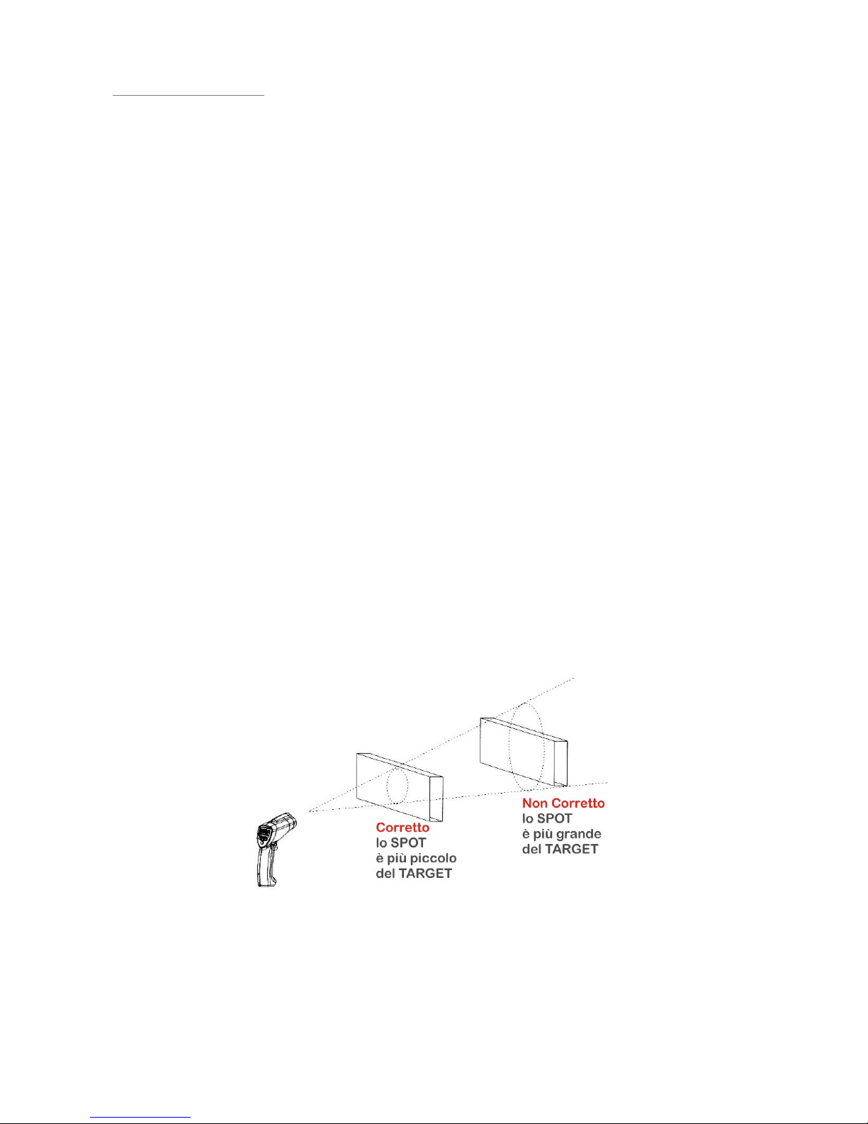
Here below a simple but clear example where you can find both the correct using , where the TARGET
contains all the spot, and an example of incorrect using where the TARGET does not contain all the spot, in
this case the instrument will display a temperature which represents the thermal average of the read surface,
in this case not totally represented by the TARGET , then as already explained, not representative of the real
temperature of the Target.
If the TARGET would be of little dimension, and there is the risk that the spot would not be completely
covered, and as the optical is with fixed focus, it is always wise where possible to bring the instrument near to
reduce the dimension of the SPOT making then the measurement compatible and more reliable.
DIFFICULT OR IMPOSSIBLE MEASUREMENT: just for the used technology, and not for a fault and/or shortage
of the instrument, there are measurement which cannot be made and that can even damage the instrument in
an irreparable way, let’s begin from these last ones:
Never point the instrument in front of the sun, the quantity of energy radiating and received by the instrument
is such to damage the instrument in an irreparable way.
Page 16

IF324_5A808_UK_M1
® Copyright CEAM Group
CEAM Control Equipment
16
Attention: this kind of damage, moreover quite frequent and typical, is not covered by the warranty.
Also the measurement on surfaces glossy, reflecting, chromium-plated, Aluminium, Bright Stainless Steel are
always very difficult to be done, and are not reliable, both for the nature of the materials, and also because of
the Emissivity constant, look at the paragraph Emissivity here below.
It is not possible to make measurements neither through mineral glass sheets, as this element operates on a
wave length different then the human eye, and if for the eye the glass is transparent, for this instrument it is
opaque as an Iron plate, then even if the laser pointer will go beyond it (its wave length allows it), the
instrument will be able to measure just the superficial temperature of the glass, and not over it.
Also Steam, Warm air, Smoke and similar cannot be measured, as they are not solid bodies, besides the
operator should keep attention in this kind of measurements, because drawing to much the instrument up you
could dirty the instrument and its optical side, producing measure errors, or even making it useless.
EMISSIVITY: As already explained before, in the infrared temperature measurements, it is necessary to set a
constant which is named Emissivity and which is typical and specific for the various kinds of materials to be
measured. Here following it is published a summary table of Emissivity of the most common materials.
ATTENTION! In case you desire to measure with more accuracy all the materials, but in particular the most
difficult ones or even impossible ones to be measured, you can do it with a simple trick, in practice it is enough
to create some point of measure (TARGET) where the surface to be measured has been modified, or where
there is applied a piece of compatible material, for example some adhesive tape well stuck, or for higher
temperature it is possible to paint beforehand these points with opaque Black Paint, it is perfect the muffler
paint which you can find on the market in chip and practical Aerosol bombs, for further information and
suggestions contact the customer service CEAM , here following anyway we publish a short table with the
Emissivity values of the main materials families
EMISSIVITY COEFFICIENT TABLE
Material Emissivity Material Emissivity
Asphalt
0.90 ÷ 0.98
Cloth
0.98
Concrete
0.94 Human Skin
0.98
Cement
0.96 Leather
0.7
5 ÷ 0.80
Sand
0.90 C
oal (Po
wder
) 0.96
Land
0.92 ÷ 0.96
Paint
0.80 ÷ 0.95
Water
0.92 ÷ 0.96
Matte Paint
0.97
Ice 0.96 ÷ 0.98
Black Rubber
0.94
Snow
0.83 Wood
0.90
Glass
0.90 ÷ 0.95
Plastic
0.85 ÷ 0.95
Ceramics
0.90 Paper
0.70 ÷ 0.94
Marble
0.94 Oxidized Chrome Steel
0.81
Gypsum
0.80 ÷ 0.90
Oxidized Copper
0.78
Malta
0.89 ÷ 0.91
Oxidized Steel
0.78 ÷ 0.82
Brick
0.93 ÷ 0.96
Fabric
0.90
Other eventual material get by experimental way
Material Emissivity Material Emissivity
Page 17

IF324_5A808_UK_M1
® Copyright CEAM Group
CEAM Control Equipment
17
9 – Maintenance
The instrument especially if used correctly does not requires particular service intervention besides the periodical
substitution of the consumable parts, as the battery, or the thermocouple probes, which are subject to wear.
Besides, also for the side of measure T/C, but in particular for the side of the IF, we suggest to verify the correct calibration
at least twice a year, using a calibration oven “Black Body / Grey Body” as the ones at disposal among the optional (Ref
Series C400 / C600), a major frequency of verifying it is suggestible in case the level of critical state of the measurement to
be made is High.
Page 18
IF324_5A808_UK_M1
® Copyright CEAM Group
CEAM Control Equipment
18
10 – The Software
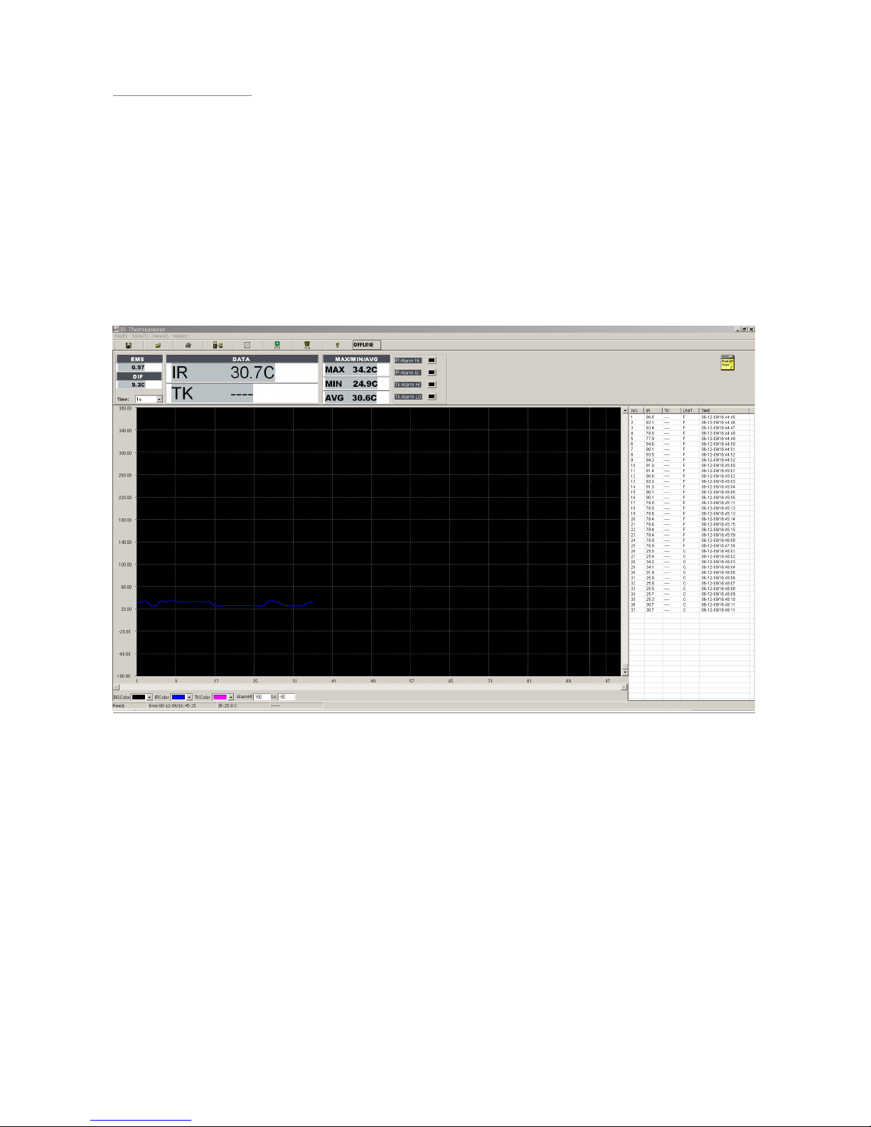
The Thermometer IF324 is equipped by a Software Utility extremely simple and intuitive, which through its USB gate allows
acquiring the data taken through a PC, as well as other several functions.
At the moment the software which is supplied for free is at disposal only in English language, as it is typical for this kind of
utility products, but as it is so simple it will not be difficult to be used also from people who do not speak English.
Before proceeding in using the software, it is necessary to install it into the PC you intend to use, the procedure is totally
automatic, you need first to install the software, and then connect the thermometer to the USB gate, activating before its
gate (Ref. Par 5.3.5) and then follow the eventual request of the system.
At the end, once you install it correctly, pressing the Trigger of the thermometer, it will be possible to see on the PC the data
taken by the thermometer, both those with technology IF and those taken by the thermocouples if connected.
If everything has been well done, you will see the screen showed here below, where the track in this case blue you can see
on the diagram, represent in this case the value of the temperature taken during time, while on the above part you can see
the actual value, as you can see by the image from the PC it will be possible to visualize also many other information,
relevant to alarms etc etc..
The software is provided by an on line manual, where you can enter in clicking on the icon with the question mark.
Page 19
IF324_5A808_UK_M1
® Copyright CEAM Group
CEAM Control Equipment
19
11 – Codes to Order Optional & Spare Parts
Art. 5A808 - IF324 – Handy Combined infrared Thermometer IF + TCK
Double Laser Pointer – USB Gate
Range IF -50.0 ÷ 1600 °C
Range TCK -50.0 ÷ 1370 °
Included Accessories:
Rigid Plastic Case
Thermocouple Type K - Art. 6006 (Low Temperature Version)
USB Cable
Software Windows
Other Version of the Series IF300 - 2008:
IF311 – Infrared Portable Thermometer for Sanitary using Range -30 ÷ 60 °C – Art. 5A804
IF321 – Handy infrared Digital Thermometer - Range -50 ÷ 380 °C – Art. 5A805
IF322 – Handy Infrared Thermometer -50 ÷ 550 °C – Art. 5A806
IF323 – Handy infrared Thermometer -50 ÷ 1600 °C – Art. 5A807
IF301D – Multi-purpose Infrared Thermometer + Thermocouple Input – Range 0 ÷ 650 @IR - 0 ÷ 1700 °C @T/C
Accessory:
Rechargeable NiMh Battery - Size 6LR61 – Art. 0942
Universal Net Battery Charger 230 Vac – 50 Hz – Art. 0943
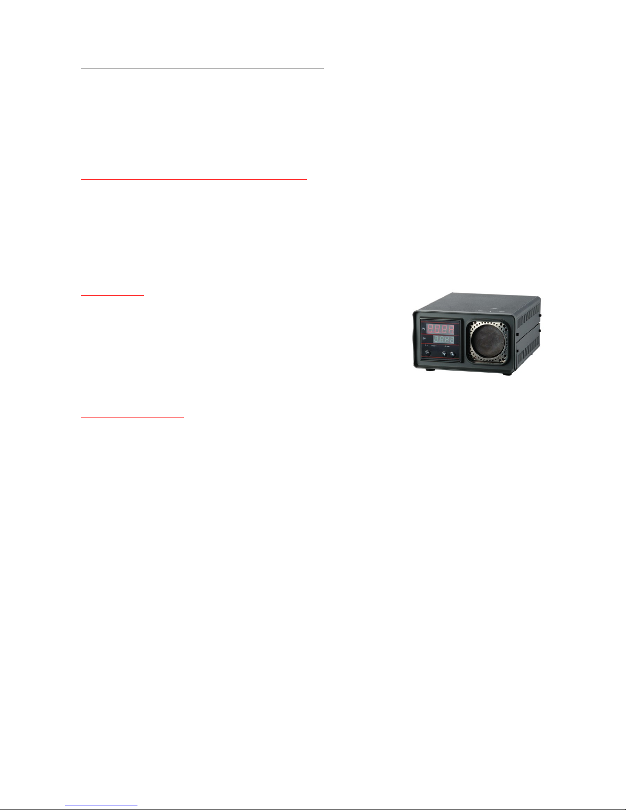
C430-A – Calibration Kiln Black Body – Range 50 ÷ 350 °C
C430-B – Calibration Kiln Black Body – Range 50 ÷ 500 °C
Technical Note: Kilns for the verifying of the Calibration of infrared Thermometers
To be used not only with the model presented on the manual, but also with other
models
Optional Services:
Service of Verify of ISO Calibration
SIT Calibration Service
Page 20
IF324_5A808_UK_M1
® Copyright CEAM Group
CEAM Control Equipment
20
11 – Warranty Terms
Attention!!
The present handbook is merely indicative, and it is subject to changes in any moment, without giving any notice.
The not respecting strictly the indication found on this handbook, the opening and tampering the product, the incorrect use, the wrong wiring,
the using of spare parts or optional not original CEAM Control Equipment, the removing of the labels, of the identification marks put by CEAM
Control Equipment, and the hidden export to Extra CE counties, they make immediately lose the responsibility over the product and the
warranty right!
WARRANY TERMS:
the product is under warranty for a period of 12 Months (Art. 1490 C.C. and following) starting by the delivery note
date, also in case it is in vision, and then transformed in selling, the complete text of the warranty conditions offered by CEAM Control
Equipment in conformity to the actual laws, are published, and are at disposal of any people which demand for them, the document is registered
both in paper form and in electronic form, to the CEAM Control Equipment, headquarter, and to see it, it is sufficient to make a written request,
specifying the title of the applicant.
The warrany cover:
The products and the components which bad functioning is referable for sure to production defects, the eventual defect met
gives only the right to repair it, and not to substitute the product, besides the eventual production defect, does not give any
right to resolute the contract, or to suspend the payment if not expressly agreed in written by CEAM.
The warranty does not cover:
Defects generated by incorrect or improper use of the product
Defects generated by using spare parts or consumables products not original CEAM
Defects generated by environmental and/or atmospheric problems and/or natural calamity
Products and/or services tampered or modified even partially
Products and/or services to which have been taken off, or tampered, even partially, labels and lot codes original CEAM
In any case, the warranty does not cover:
Batteries, magnetic devices, perishable products and/or consumable products
The components of Third parts, to which it must answer directly, the assistance service of the same, with the modalities provided from them.
The technical time used to verify and/or to repair the products
The travelling allowance, and the technical intervention on the place, if effected.
The packaging and shipping cost of the products there and back.
All the additional costs supported by CEAM to fulfil the warranty.
Clause of responsibility exclusion
CEAM does not assume any responsibility, regarding eventual damages, direct or in direct, caused to people or things, or damages for non
production and/or incorrect production and/or eventual damage, in some way referable to the product and/or to this handbook service.
CEAM does not assume any responsibility regarding eventual damages caused to people or things because of the eventual not conformity to
the product and/or service of the present handbook, which is merely indicative, and that can be changed by CEAM in any moment without giving
any notice.
Page 21

IF324_5A808_UK_M1
® Copyright CEAM Group
CEAM Control Equipment
21
Page 22

IF324_5A808_UK_M1
® Copyright CEAM Group
CEAM Control Equipment
22
Page 23

IF324_5A808_UK_M1
® Copyright CEAM Group
CEAM Control Equipment
23
Page 24

IF324_5A808_UK_M1
® Copyright CEAM Group
CEAM Control Equipment
24
CEAM
Control Equipment srl
Headquarters:
Via Val D’Orme No. 291
50053 Empoli (Firenze) Italy
Tel. (+39) 0571 924082 - Fax. (+39) 0571 924505
Skype Name: ceam_info
Internet:
Group Web: www.ceamgroup.com
Division Web: www.ceamcontrolequipment.it
Support Web: www.ceamsupport.it
Service E.mail:
General: [email protected]
Customer Service: [email protected]
Local Reseller:
 Loading...