

Page 1
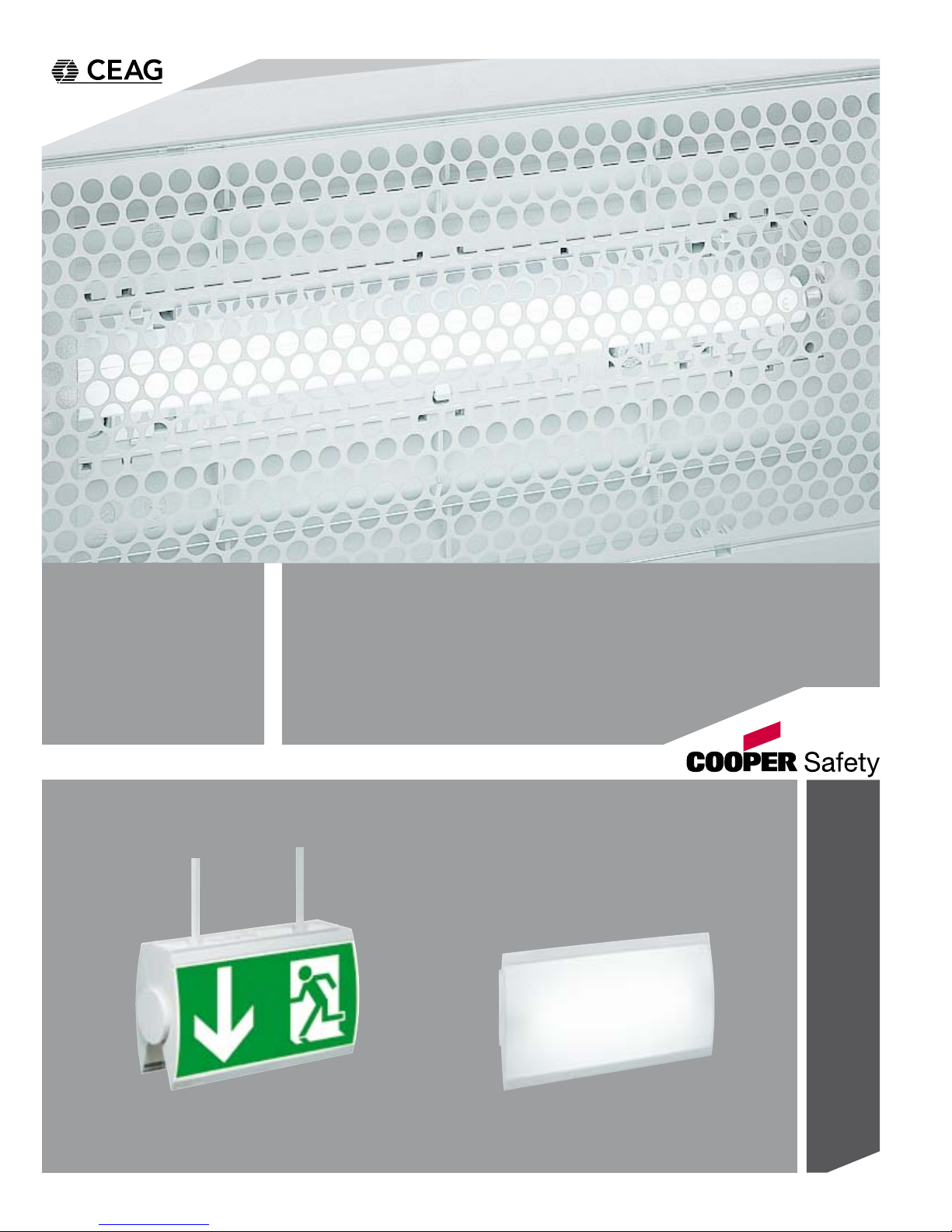
Montage- und Betriebsanleitung
Mounting and Operating Instructions
Style 55011,-021 CG-S
Style 55011,-021
Zielgruppe: Elektrofachkraft
Target group: Skilled electricians
Page 2

2
Montage und Betriebsanleitung
Style 55011 / 55021 (CG-S)
Inhaltsverzeichnis
1 Aufbau und Maßbilder.....................................................
1.1 Aufbau der einseitigen Leuchten.......................................
1.2 Aufbau der zweiseitigen Leuchten.....................................
1.3 Maßbilder...........................................................................
2 Sicherheitshinweise....................................................
3 Normenkonformität.....................................................
4 Technische Daten.........................................................
4.1 Kurzbeschreibung / Verwendungsbereich.........................
5 Installation......................................................................
5.1 Montage..............................................................................
5.2 Montagezubehör.................................................................
5.3 Adressierung (nur STYLE 550.. CG-S)................................
6 Instandhaltung / Wartung...........................................
7 Recycling.........................................................................
.
Table of Contents
1 Construction and dimensional drawings................
1.1 Construction of the single-sided luminaire..........................
1.2 Construction of the two-sided luminaire.............................
1.3 Dimensional drawings.........................................................
2 Safety instructions........................................................
3 Conformity with standards.........................................
4 Technical Data................................................................
4.1 Brief description / Field of application................................
5 Installation......................................................................
5.1 Mounting............................................................................
5.2 Mounting accessories........................................................
5.3 Addressing (only STYLE 550.. CG-S).................................
6 Servicing / Maintenance.............................................
7 Recycling.........................................................................
3
3
4
5
6
6
6
6
7
7
7
8
8
8
3
3
4
5
9
9
9
9
10
10
10
11
11
11
Page 3
3
Montage und Betriebsanleitung
Style 55011 / 55021 (CG-S)
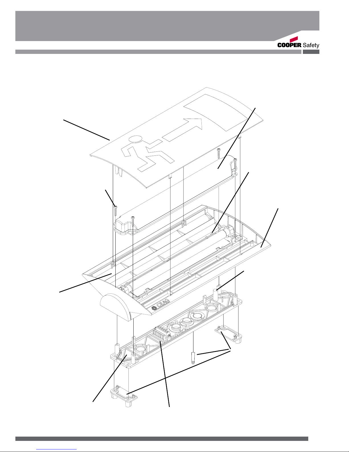
1.1 Aufbau der einseitigen Leuchte
1.1 Construction of the single-sided luminaire
Bild 1 / Fig. 1
Scheibe
Screen
IP 54 Zubehörsatz
IP 54 accessories kit
Schnellmontagesatz
Quick mounting plate
Führungsstift
Guide pin
Öffnung für Führungsstift
Hole for guide pin
Abstandselemente
Spacer elements
Leuchtenkörper
Body of luminaire
IP 54 Abdeckhaube
IP 54 bowl
Raum zwischen
Haube und
Piktogrammscheibe
IP 41!
Area between bowl and
pictograph plate IP41!
Anschlussraum IP 54
connection area IP 54
Bei Aufsatzmontage oder IP54
Montagesatz sind die 3 beiliegenden Abstandhalter im Schnellmontagesatz zu verwenden.
For surface mounting or IP54
installation use the 3 enclosed
spacers in the quick-Mounting
set.
Page 4
4
Montage und Betriebsanleitung
Style 55011 / 55021 (CG-S)
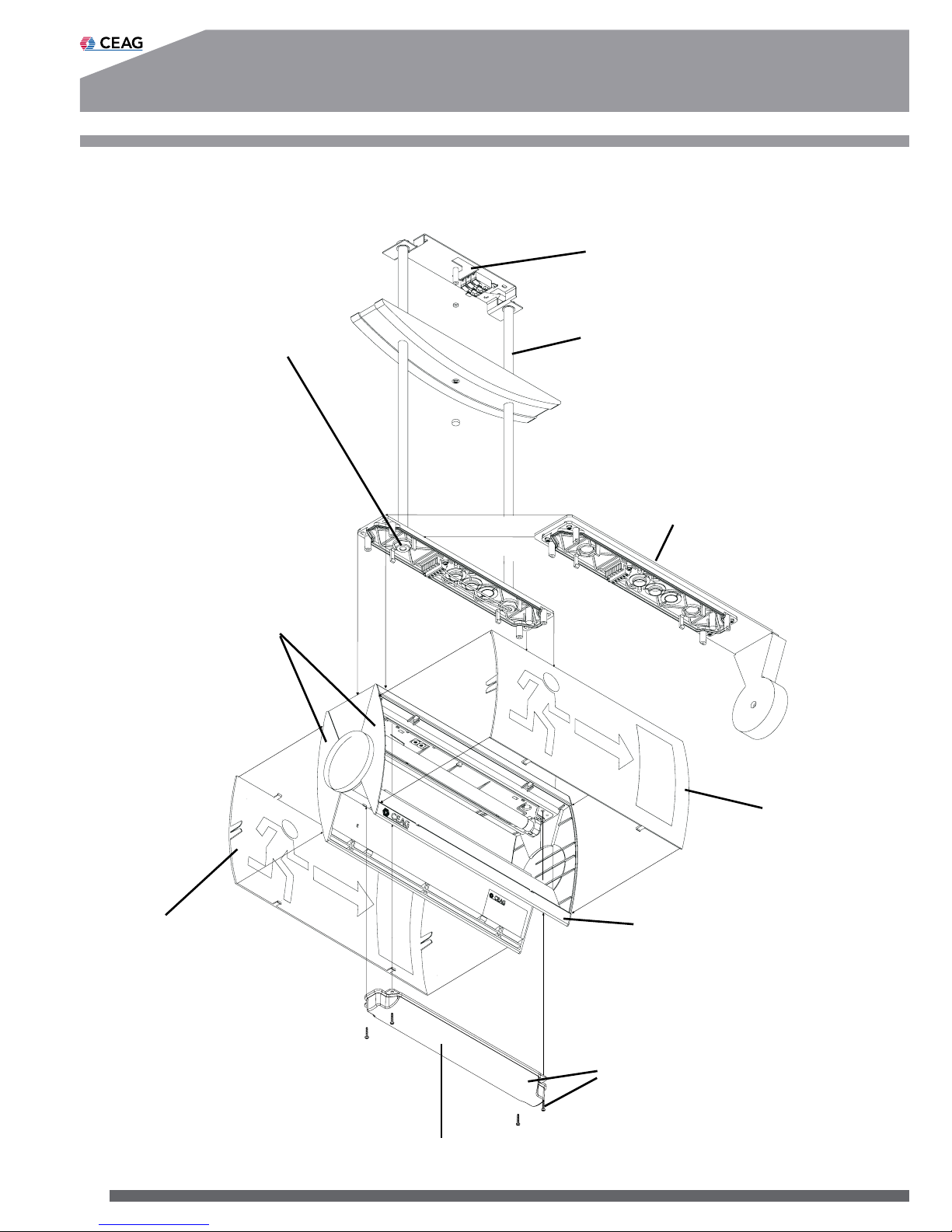
1.2 Aufbau der zweiseitigen Leuchte
1.2 Construction of the two-sided luminaire
Deckenpendel mit Abdekkung (Zubehör)
Ceiling pendulum with cover
(accessory)
Wandausleger (Zubehör)
Wall bracket (accessory)
Scheibe
Screen
Scheibe
Screen
Leuchtenkörper
Body of luminaire
IP 54 Zubehörsatz
IP 54 accessories kit
(Abdeckhaube, 4 Schrauben.
Bowl, 4 screws.)
Bild 2
fig. 2
Anschlussraum IP 41
Connection area IP 41
IP 54 Abdeckhaube
IP 54 bowl
Anschlussraum IP 54
connection area IP 54
Raum zwischen
Haube und
Piktogrammscheibe
IP 41!
Area between bowl and
pictograph plate IP41!
Page 5
5
Montage und Betriebsanleitung
Style 55011 / 55021 (CG-S)
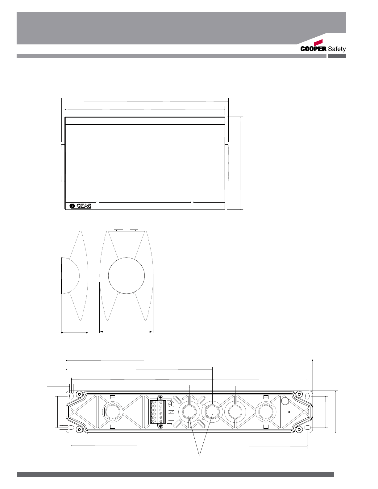
1.3 Maßbilder
1.3 Dimensional Drawings
41
Schnellmontagesatz / Quick mounting plate
Bild 3
fig. 3
TOP
322
193
308
30 30
41
309
5
5
55
PG 11
355
225
60
118
Typ: 55011 Typ: 55021
Page 6
6
Montage und Betriebsanleitung
Style 55011 / 55021 (CG-S)
3. Normenkonformität
Leuchte für Notbeleuchtung gem.
EN 60 598-2-22, zum Anschluss
an Sicherheitsbeleuchtungsanlagen gem. DIN VDE 0100-718, EN
50 172 und E DIN VDE 0108-100.
Verwendetes EVG konform mit:
EN 60 929, EN 61 347-2-3 und
EN 61 347-2-4.
Gemäß ISO 9001 entwickelt,
gefertigt und geprüft.
4. Technische Daten
Anschluss- 220-240 V DC
spannung: 50/60 Hz
176 - 275V DC
Standby Verlustleistung: <0,5W
Leistungsfaktor: 0,6
Einschaltstoßstrom: 3A/ms
Betriebsfrequenz: 44kHz
Stromaufnahme (AC): 60 mA
Leistungsauf nahme (AC): max. 16 VA
Stromaufnahme (DC): 30 mA
Lampe: 8 W nach
81-IEC-1040-1
Nennlichtstrom
der Lampe: 450 lm
Bemessungslichtstrom: 75 % (Phi
Netz
)
Schutzklasse: II
Schutzart nach
EN 60529: IP 41
Option: IP 54
Umgebungstemperatur: -10 °C .. +40 °C
Netzanschlussklemmen: 3 x 2 x 2,5 mm²
Gewicht: 0,85 kg (eins.)
1,0 kg (zweis.)
4.1 Kurzbeschreibung /
Verwendungsbereich
Rettungs- oder Sicher heitsleuchten für den Betrieb an CEAG
Sicherheitsbeleuchtungsanlagen
mit Einzelleuchtenüberwachung
(Cewa-Guard-Technologie) und/
oder mit programmierbarer
Schaltbarkeit im Endstromkreis
(STAR-Technologie) geeignet.
Die Leuchten Style 55011,-021
(ohne Zusatz CG-S) sind ohne
2. Sicherheitshinweise
Die Leuchte ist bestim mungs gemäß in unbeschä digtem und einwandfreiem
Zustand zu betreiben!
Als Ersatz dürfen nur Origi nalteile von CEAG verwen det werden!
Bei Durchführung von
Arbeiten an der Notleuchte
ist erst die Anlage zu blo-
ckieren, der Batteriekreis zu
unterbrechen und dann das
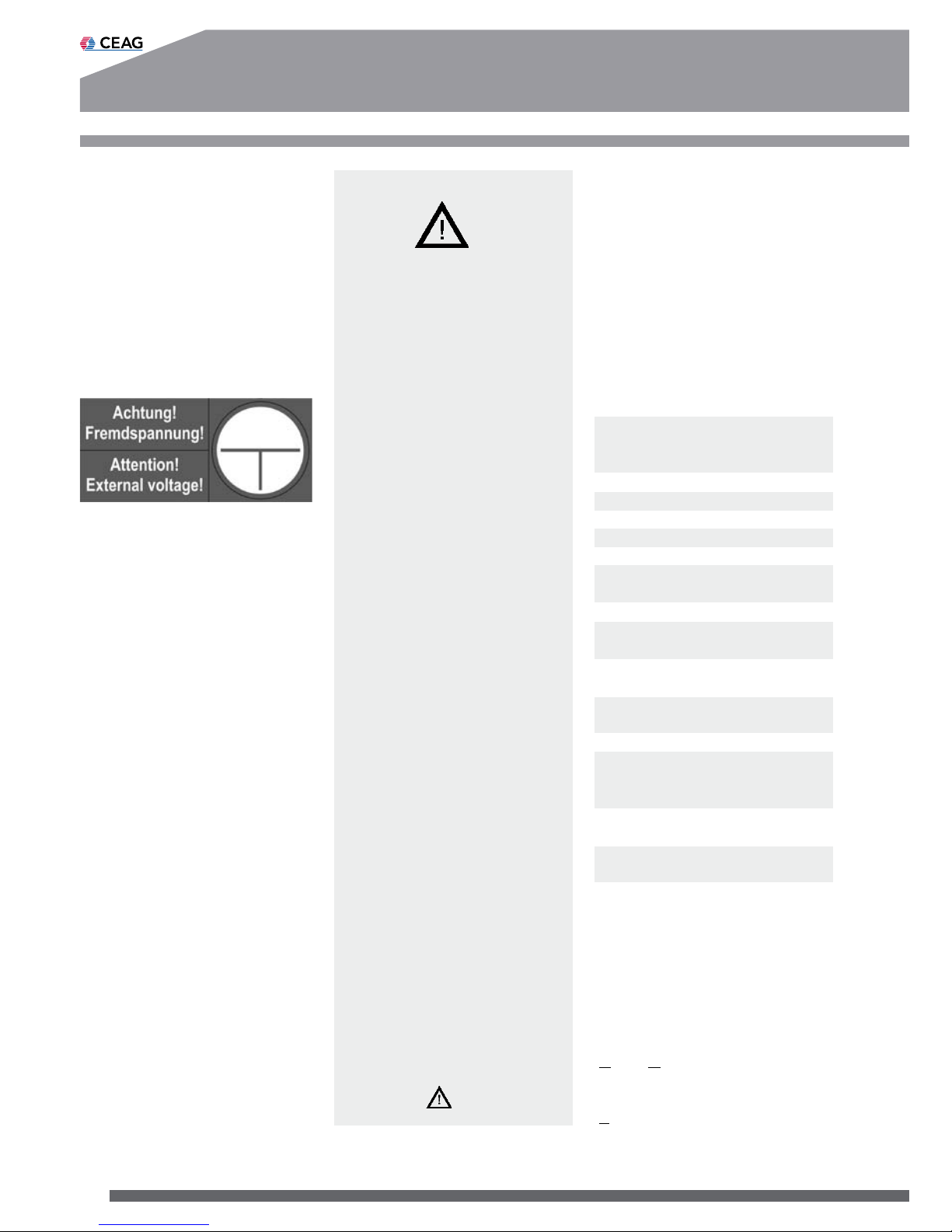
Netz abzuschalten. Bild 4
zeigt das Hinweisschild auf
der Notleuchte.
Vor der ersten Inbetrieb nahme muss die Leuchte
entsprechend den im Ab schnitt Installation ge nannten Anweisungen ge prüft werden!
Die Notleuchtenkenn zeich nung vornehmen: Strom kreis und Leuchtennummer
zuordnen und eintragen.
Die Protokollführung gemäß
der nationalen Vorschriften
ist durchzuführen (entfällt
bei automatischer Protokol lierung)!
Alle Fremdkörper müssen
vor der ersten Inbetrieb nahme aus dem Gerät
entfernt werden!
Beachten Sie bei allen
Ar beiten an dem Gerät die
nationalen Sicherheits- und
Unfallverhütungsvorschrif ten und die nachfolgenden
Sicherheitshinweise in der
Betriebsanleitung, die mit
einem versehen
sind!
Bild 4
Page 7
7
Montage und Betriebsanleitung
Style 55011 / 55021 (CG-S)
5. Installation
Halten Sie die für das
Errichten und Betrei-
ben von elektrischen
Betriebsmitteln geltenden
Sicherheitsvorschriften und
das Gerätesicherheitsgesetz
sowie die allgemein anerkann ten Regeln der Technik ein!
5.1 Montage
Nach Befestigung des Schnellmontagesatzes gemäß zugehöriger Anleitung ist die
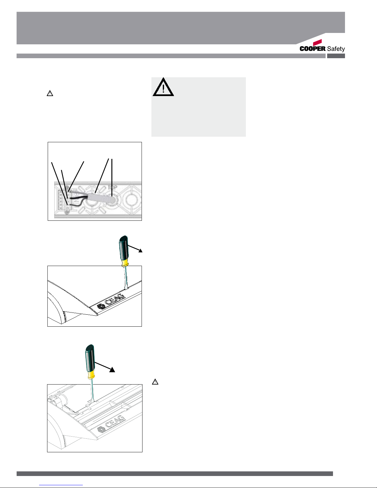
Netzver bindung (L(U), N(0), PE)
herzustellen (Bild 5). Achten Sie
auf den festen Sitz der Klemmschrauben! Nichtbenutzte Einführungen sind mit montiertem
Ver schlussstopfen zu belassen
(IP-Schutz).
Zur Montage der Leuchte ist die
Öffnung im Leuchtenkörper auf
den Führungsstift (Bild 1) des
Schnellmon tagesatzes aufzusetzen. Alle vier Ecken am unteren Teil des Leuchtenkörpers
sind bis zum deutlichen Rasten
auf den Schnellmontagesatz
aufzudrücken (Schnapphaken
rasten am Schnellmontagesatz).
Bei Installation der Leuchte in
IP 54 Schutzart ist der IP 54 Zubehörsatz mit 4 Schrauben zu
befestigen.
Mit den zugehörigen Formschrauben 3,5 x 16 ist die
Haube gleichmäßig auf dem
Schnellmontagesatz festzuschrauben.
Schrauben nur handfest
(max. 0,8 Nm) anziehen!
Zum Lampenwechsel oder der
Adressierung sind Schnapphaken der Scheibe mit einem
Schlitzschraubendreher zu lösen (Bild 6).
Zum Lösen des Leuchtenkörpers vom Schnellmontagesatz
ist ein Schlitzschrauben dreher
in die seitliche Aussparung am
Reflektor zu stecken (Bild 7)
und der Schnapphaken durch
seitliche Hebelwirkung in Richtung Außenkante zu lösen.
Mit leichtem Ziehen innen am
Leuchtenkörper löst sich selbiger vom Schnellmontagesatz.
Nachdem alle vier Schnappverbindungen gelöst sind, kann der
Leuchtenkörper vom Schnellmontagesatz getrennt werden;
bei IP 54 müssen zusätzlich die
4 Schrauben gelöst werden.
5.2 Montagezubehör
Pendelaufhängung
(CEAG Nr. 400 71 345 972)
Wandausleger
(CEAG Nr. 400 71 345 974)
Schnellmontagesatz
(CEAG Nr. 400 71 345 980)
IP 54 Zubehörsatz
(CEAG Nr. 400 71 345 975)
Die beigefügte Montageanleitung ist zu beachten.
Eine Sonderausführung für
die Pendelbefestigung mit der
Schutzart IP 54 ist unter der
CEAG Nr. 400 71 345 944 erhältlich.
Kettenbefestigung
(CEAG Nr. 400 71 345 973)
Ballschutzkorb
(CEAG Nr. 400 71 345 911)
Bild 6
Bild 5
PG 11
L(U) PE
N(0)
Bild 7
Überwachungselektronik ausgerüstet und somit weder adressierbar,
noch schaltbar.
In IP54 Ausführung eignen sich
die Leuchten für erhöhte Dichtigkeitsanforderungen in Innenräumen
und geschützten Außenbereichen
(z. B. unter Vordächern). Sie sind
nicht geeignet für den generellen
Einsatz im Außenbereich!
Page 8
8
Montage und Betriebsanleitung
Style 55011 / 55021 (CG-S)
- Technische Änderungen vorbehalten -
5.3 Adressierung
(nur CG-S Leuchten)
Vor Montage der Scheibe
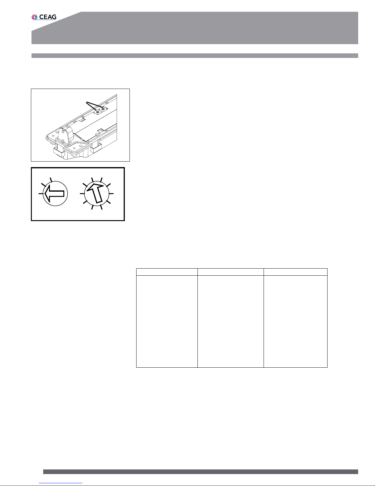
muss die individuelle Leuchtenadressierung eingestellt
werden. Hierzu ist mit einem
geeigneten Schraubendreher
die gewünschte Adresse (1 - 20)
am Adressschalter einzustellen
(Pfeil auf Zahl, Bild 8). Soll die
Leuchte nicht überwacht werden, ist immer die Stellung
0/0 einzustellen.
Die Leuchten STYLE 55011 /
55021 (ohne Zusatz CG-S) sind
nicht mit einer Überwachungselektronik ausgerüstet und sind
nicht adressierbar.
6. Wartung /
Instandhaltung
Halten Sie die für Instandhaltung, Wartung und Prüfung von
elektrischen Betriebsmitteln
geltenden Bestimmungen ein!
Bei sachgerechtem Betrieb und
unter Beachtung der Montagehinweise und Umgebungsbedingungen ist keine ständige
Wartung erforderlich.
7. Entsorgung /
Recycling
Beachten Sie bei der Entsorgung defekter Geräte die gültigen Vorschriften hinsichtlich
Recycling und Entsorgung.
Kunststoffmaterialien sind mit
entsprechenden Symbolen gekennzeichnet.
Adressschalter
Bild 8 Adressschalter
0
1
2
3
4
5
6
7
8
9
0
1
2
Schalter 1 Schalter 2
Adressschalter 1 Adressschalter 2 Leuchtenadresse
0 0 Überwachung aus
0 1 1
0 2 2
... ... ...
1 0 10
1 1 11
... ... ...
... ... ...
2 0 20
2 1 nicht zulässig
... ... ...
2 9 nicht zulässig
Page 9
9
Mounting and Operating Instructions
Style 55011 / 55021 (CG-S)
2. Safety Instructions
The device shall only be used
for its intended purpose and
in undamaged and perfect
condition!
Only genuine CEAG spare
parts may be used for replacement and repair!
When working on the emer-
gency luminaire first the system must be blocked, battery
operation must be interrupted
and mains must be cut off.
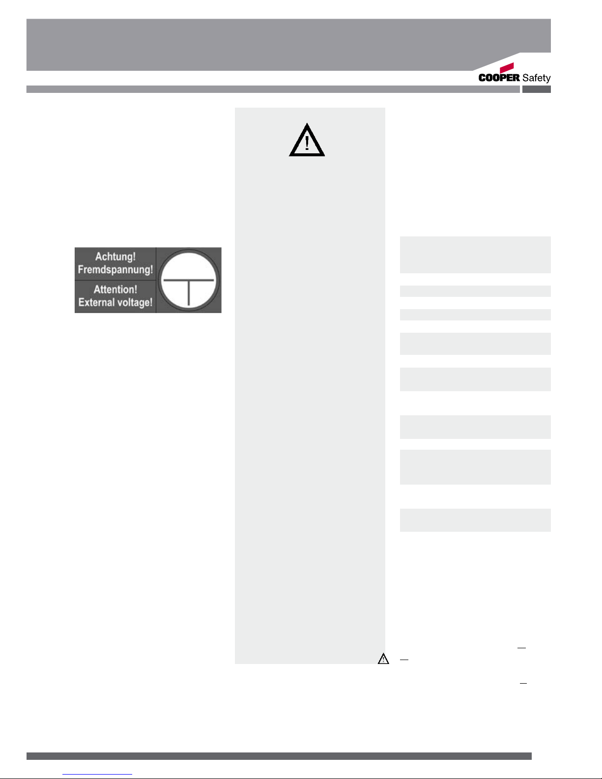
Fig. 4 shows the indication
label on the emergency luminaire.
Prior to its initial operation,
the luminaire will have to be
checked in accordance with
the instructions as per section
Installation!
Carry out the marking of the
emergency luminaire: Assign
the circuit and the luminaire
No. and enter them.
Recording in the minutes shall
be performed in compliance
with the national regulations
(is deleted in case of automatic recording).
Any foreign matter shall be
removed from the luminaire
prior to its initial operation!
While undertaking any ser-
vicing on the luminaire, the
national safety rules and regulations for prevention of accidents shall be observed as
well as the safety instructions
included in these operating
instructions marked with a
3. Conformity with
standards
Luminaire for emergency lighting
acc. to EN 60 598-2-22 for connection to safety luminaire
Fig. 4
systems acc. to DIN VDE 0100718, EN 50 172 and E DIN VDE
0108-100. Used ECG is conform
to:
EN 60 929, EN 61 347-2-3 and
EN 61 347-2-4.
Designed, manufactured and
tested according to DIN EN ISO
9001.
4. Technical data
Power input: 220-240 V AC
50/60 Hz
176 - 275 V DC
Standby power loss: < 0.5W
Power factor: 0.6
Inrush current: 3A/ms
Operating frequency: 44 kHz
Rated current (AC): 60 mA
Power consumption (AC): max. 16 VA
Rated current (DC): 30 mA
Lamp: 8 W acc. to
81-IEC-1040-1
Rated luminous flux of
the lamp: 450 lm
Rated luminous flux for emergency operation: 75 % (phi
mains
)
Insulation class: II
Protection category acc.
to EN 60529: IP 41
At option: IP 54
Perm. ambient
temperature: - 10 °C ..+ 40°C
Supply
terminals: 3 x 2 x 2.5 mm²
Weight: 0.85 kg (single
side)
1.0 kg (two-sid.)
4.1 Brief description /
Scope of application
Exit or safety luminaire, suitable
for operation on CEAG safety
lighting systems with single
luminaire monitoring (CewaGuard-Technology) and/or with
programmable switching mode
in the outgoing circuit (STARtechnology).
The Style 55011,-021 (without
CG-S) are not fitted with monitoring electronic and so neither
addressable nor switchable.
Page 10
10
Mounting and Operating Instructions
Style 55011 / 55021 (CG-S)
5. Installation
For the mounting and operation
of electrical apparatus,
the respective national
safety regulations (e. g.
ElexV, equipment safety law for
Germany) as well as the gen
eral rules of engineering will
have to be observed.
5.1 Mounting
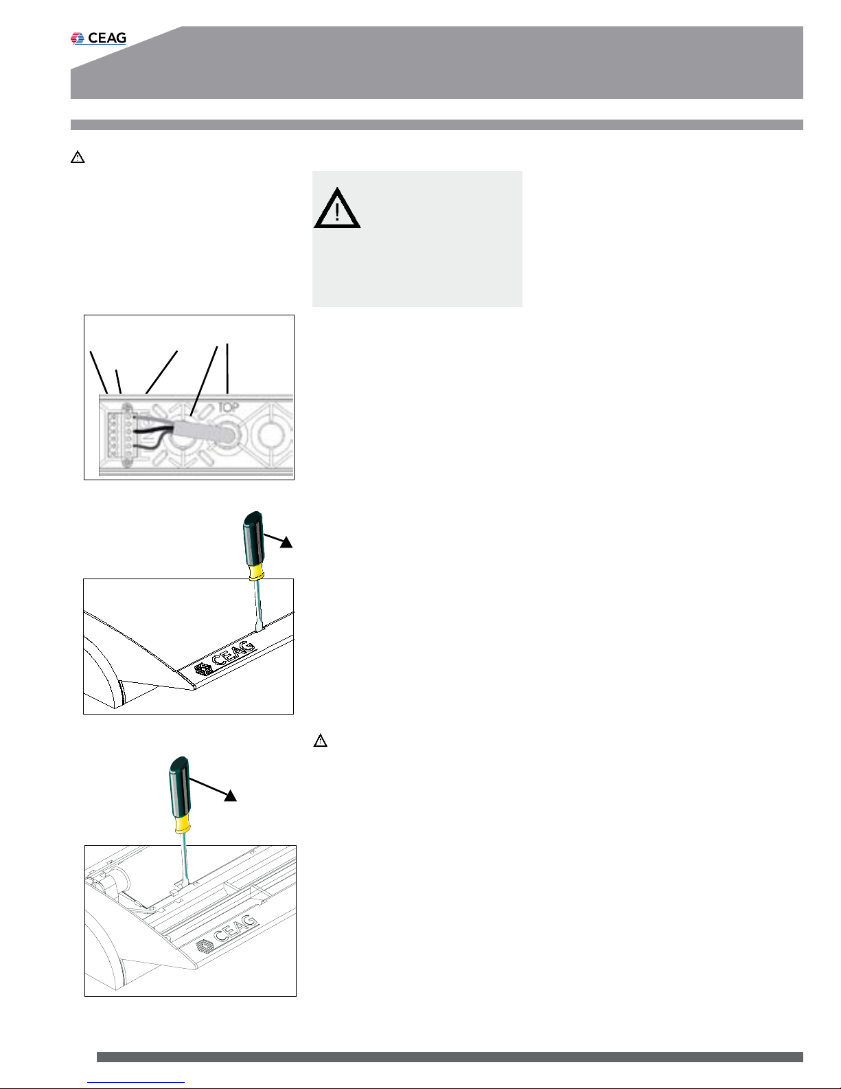
After fixing the quick mounting
plate in accordance with the respective instructions, the mains
connection (L (U), N (0), PE) is to
be established (fig. 5). Pay attention to a tight fit of the terminal
screws! Unused cable entries are
left with their locking plug fitted
(IP protection).
In order to fix the luminaire, the
opening in the body of the luminaire is placed on the guide
pin (fig. 1) of the quick assem-bly
plate. Then all four corners of the
body of the luminaire are pushed
down until they distinctly lock in
on the quick mounting plate (the
snap hooks engage in the quick
mounting plate). When installing
the luminaire with IP 54 protection, the IP 54 accessories kit is
to be fixed with 4 screws.
Using the pertaining selfcutting screws 3.5 x 16, the bowl
is evenly screwed down on the
quick mounting set.
Only use handforce to tighten the
screws (max. 0.8 Nm)!
For lamp replacement or addressing, the snap hooks of the
screen are detached with a slotted screw driver (fig. 6).
In order to detach the body of
luminaire from the quick mounting plate, a slotted screw driver
is inserted into the lateral recess
on the reflector (fig. 7). Through a
slight lateral lever action towards
the outer edge, the snap hook is
released. When slightly pulling
the body of luminaire from the
inside, it disengages from the
quick mounting plate. After having released all four snap connections, the body of luminaire
can be removed from the quick
mounting plate; in case of the
IP 54 version the 4 screws will
have to be unscrewed.
5.2 Mounting accessories
Pendulum set
(CEAG No. 400 71 345 972)
Wall bracket
(CEAG No. 400 71 345 974)
Quick mounting plate
(CEAG No. 400 71 345 974)
IP 54 accessories kit
(CEAG No. 400 71345 975)
The attached mounting instructions have to be observed!
A special version for pendulum
suspension with IP 54 protection is available under the CEAG
No. 400 71 345 944.
Chain suspension
(CEAG No. 400 71 345 973)
Wire guard
(CEAG No. 400 71 345 911)
5.3. Addressing (only
CG-S luminaires)
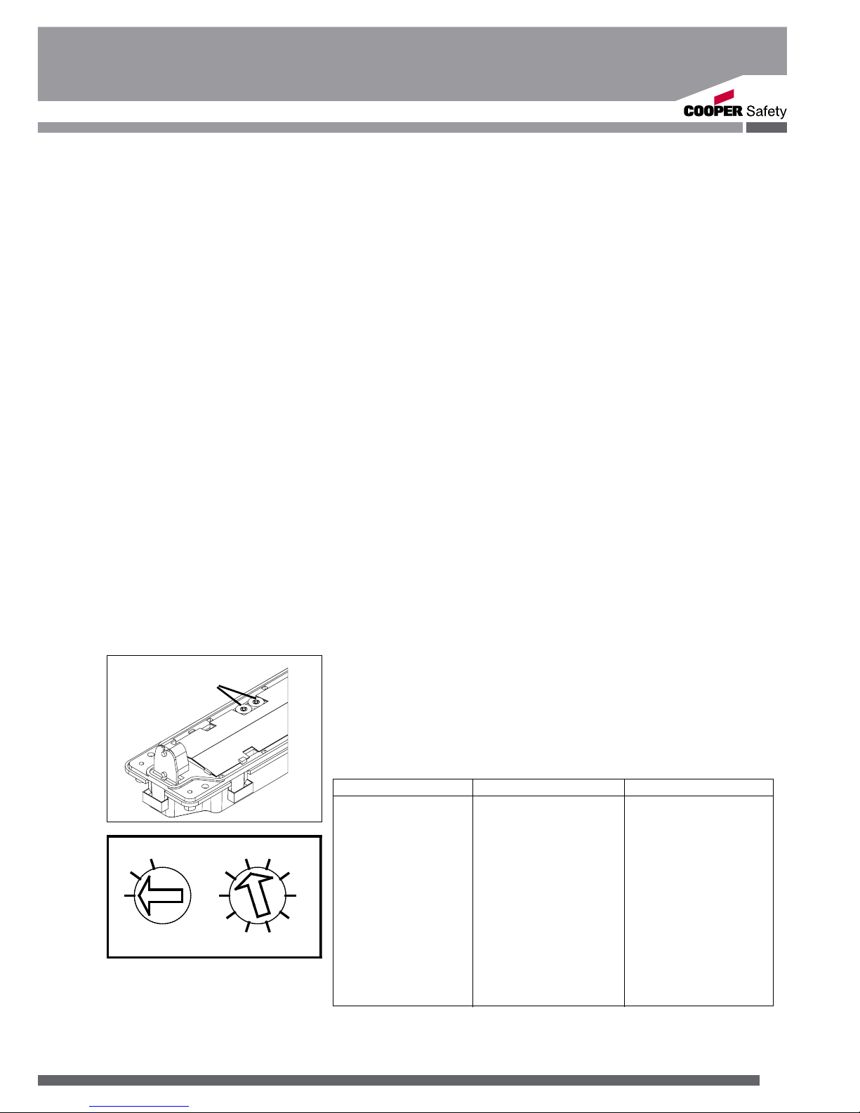
Before fitting the screen or
bowl, the addressing of the
individual luminaires will have
to be performed. To do so,
the desired address (1 - 20) is
set on the address switch by
means of a suitable screw driver (Arrowhead to No., fig. 8).
If the luminaire should not be
monitored the code 0/0 has to
be selected.
Fig. 7
Fig. 6
Fig. 5
L(U) PE
N(0)
PG 11
The luminaires with IP54 are
suitable for increased sealing requirements for indoor rooms and
protected outdoor areas (e.g. under
porches). They are not suitable for
general use in outdoor areas!
Page 11
11
Mounting and Operating Instructions
Style 55011 / 55021 (CG-S)
The luminaire STYLE 55011
and 55021 (without CG-S) are
not equipped with monitoring
circuit and will not be addressable.
6. Servicing /
Maintenance
Observe the relevant national
regulations which apply to the
maintenance, servicing and
check of electrical apparatus (in
Germany DIN VDE 0105, part
9)! On condition of an appropriate operation and of observing
the mounting instructions and
environmental conditions, no
permanent servicing will be
required.
Address switch
fig. 8 Address switch
0
1
2
3
4
5
6
7
8
9
0
1
2
Switch 1 Switch 2
Address switch 1 Address switch 2 Luminaire address
0 0 Monitoring off
0 1 1
0 2 2
... ... ...
1 0 10
1 1 11
... ... ...
... ... ...
2 0 20
2 1 not permissable
... ...
2 9 not permissable
-We reserve the right to carry
out technical changes!-
7. Disposal /
Recycling
When a defective apparatus
is disposed of, the respective
national regulations on waste
disposal and recycling will
have to be observed. Plastic
parts have been provided with
respective symbols.
Page 12

300 80 001 612(I)/XXX/07.12/WK
CEAG Notlichtsysteme GmbH
Senator-Schwartz-Ring 26
59494 Soest
Germany
Cooper Safety
Jephson Court
Tancred Close
Royal Leamington Spa
Warwickshire CV31 3RZ
United Kingdom
Tel: +44 (0) 1926 439200
Fax: +44 (0) 1926 439240
Web: www.cooper-safety.com
Email: [email protected]
 Loading...