


EN
Operator’s manual
READ CAREFULLY
CEA COSTRUZIONI ELETTROMECCANICHE ANNETTONI S.p.A.
C.so E. Filiberto, 27 - 23900 Lecco - Italy
Tel. ++39.0341.22322 - Fax ++39.0341.422646
Cas. Post. (P.O.BOX) 205
E-mail: cea@ceaweld.com - web: www.ceaweld.com
1020HC19D-EN-09/2018 SN - KI xxxxxx

EN
ENGLISH
Introduction 3
Control panel 3
KEY AND KNOB COMMANDS 3
DISPLAY AND LED INDICATIONS 4
Switching on the welding machine and initial screen 4
Viewing the software version installed 4
Loading of the wire 5
Special functions “Fx” 5
SETUP Menu 6
FACTORY DEFAULT (FAC) 6
Menu SPECIAL FUNCTIONS 7
SAFETY CALIBRATION CODE (SCC) 7
MOTOR CALIBRATION (Mot CAL) 7
MIG-MAG synergic / MIG pulse / double pulsed MIG 8
1 - WELDING PROCESS SELECTION 8
2 - SELECTION OF WELDING PROGRAMME 9
3 - WELDING MODE SELECTION 9
4 - SPECIAL FUNCTIONS “Fx” SELECTION 9
5 - PRE-SETTING 10
Electrode (MMA) 14
1 - WELDING PROCESS SELECTION 14
2 - SELECTION OF WELDING PROGRAM 14
3 - SPECIAL FUNCTIONS “Fx” SELECTION 14
4 - PRE-SETTING 15
5 - WELDING 15
6 - HOLD 15
7 - ACTIVATING THE VRD DEVICE 16
TIG with “Lift” striking 16
1 - WELDING PROCESS SELECTION 16
2 - SPECIAL FUNCTIONS “Fx” SELECTION 16
3 - PRE-SETTING 17
4 - WELDING 17
5 - HOLD 17
JOB 18
1 - CREATING AND SAVING A JOB 18
2 - JOB SELECTION 18
3 - PRE-SETTING / VIEWING MEMORISED JOB
DATA 18
4 - WELDING 18
5 - HOLD 19
6 - MODIFICATION AND OVERWRITING OF A
MEMORISED JOB 19
7 - DELETING A JOB SAVED 19
6 - WELDING 10
7 - HOLD 11
MIG-MAG manual 11
1 - WELDING PROCESS SELECTION 11
2 - WELDING MODE SELECTION 11
3 - SPECIAL FUNCTIONS “Fx” SELECTION 12
4 - PRE-SETTING 12
5 - WELDING 13
6 - HOLD 13
Error condition 19
2

Introduction
Il presente manuale contiene tutte le informazioni necessarie per
This manual contains all the information necessary to make the
best use of this control panel. This control panel is specifically for
multi-process welding machines: MIG-MAG, PULSED MIG, DOU
BLE PULSED MIG, MMA and TIG.
Control panel
KEY AND KNOB COMMANDS
▪ ENCODER knob - A
▪ PARAMETER
SELECTION key - A
▪ ENCODER knob - V
▪ PARAMETER
SELECTION key - V
WARNING: No LED switches on when this key is activated!
■ WELDING MODE SELECTION key
This is used to select the following welding modes (only for MIG
welding processes) and each time the key is pushed the welding
machine moves on to select the next welding mode in the follow-
ing order:
TWOSTROKE(2T)
2T LED (
) switched on
Pressing the TORCH TRIGGER starts the welding cycle, which
will stop when it is released.
FOUR STROKE (4T)
4T LED (
) switched on
1) Pressing and releasing the TORCH TRIGGER will start the
welding cycle.
2) Pressing and releasing the TORCH TRIGGER will start the
welding cycle.
CRATER2T
2T LED (
) switched on - CRATER LED ( ) switched on
1) When the TORCH TRIGGER is pushed the arc ignites and the
parameters assume the values for the “initial crater” for a time
set by means of the CRATER START TIME (F10) function.
After that the parameter values become those for “welding” for
a time defined by the CRATER START SLOPE (F11) function.
2) When the TORCH TRIGGER is released the parameters take
on the “final crater” values for a time set by means of the CRATER END TIME (F15) function, for a period of time set using
the CRATER END SLOPE (F12) function.
▪ WELDING PROCESS
SELECTION key
▪ SAVE “MEM” key
▪ PROGRAMME SELECTION key
▪ SET-UP MENU Key
▪ WELDING MODE
SELECTION key
▪ SPECIAL FUNCTIONS
key “Fx”
■ PARAMETER SELECTION key - A
This is used to select the following welding parameters:
• THICKNESS OF WELDED ITEM (
• WELDING CURRENT (
• WIRE SPEED (
).
).
).
■ ENCODER knob - A
This is used to set and edit the PARAMETERS - A based on the
corresponding LED switched on and the value highlighted on the
DISPLAY PARAMETERS - A display, required for correct functioning of the machine.
■ PARAMETER SELECTION key - V
This is used to select the following welding parameters:
• ARC LENGTH ADJUSTMENT (
• WELDING VOLTAGE (
).
• ELECTRONIC INDUCTANCE (
).
).
■ ENCODER knob - V
This is used to set and edit the PARAMETERS - V based on the
corresponding LED switched on and the value highlighted on the
DISPLAY PARAMETERS - V display, required for correct functioning of the machine.
■ PROGRAMME SELECTION key
It can be used to select the individual welding PROGRAM for MIGMAG and MMA welding processes.
■ SET-UP MENU Key (T > 3 s)
This provides access to the SET-UP menu, which in turn provides
access to a series of functions, suitable for an expert operator.
■ WELDING PROCESS SELECTION key
It can also be used to select the following welding processes:
• MIG-MAG / PULSED MIG / Double PULSED MIG.
• MMA.
• TIG.
• JOB.
■ SAVE“MEM”key(T≥2s)
It allows the saving of the parameters in the JOB.
It also allows one to view / change the parameters previously saved
in the JOB.
CRATER 4T
4T LED (
) switched on - CRATER LED ( ) switched on
1) When the TORCH TRIGGER is pushed the arc ignites and the
parameters assume the values for the “initial crater”.
2) When the TORCH TRIGGER is released the parameters
take on the “welding” values for a time set using the CRATER
START SLOPE (F11) function.
3) When the TORCH TRIGGER is pushed again the parameters
take on the “final crater” values for a time defined using the
CRATER END SLOPE (F12) function.
4) Releasing the TORCH TRIGGER will end the welding cycle.
SPOTWELDING2T
2T LED (
) switched on - SPOT LED ( ) switched on
This is used so that on pressing the TORCH TRIGGER spot welding is done for a time period set beforehand (in seconds), after
which the arc switches off automatically (SPOT WELD TIME F07
function).
STITCHWELDING2T
2T LED (
) switched on - SPOT LED ( ) flashing
To begin stitch welding:
1) Press the TORCH TRIGGER to start the welding current and
wire feed.
At this point the welder will perform automatically a succession
of a welded tracts followed by a pause, respecting the times
set in the functions STITCH WELD TIME (F05) and STITCH
WELD PAUSE (F06).
This procedure stops automatically only when the TORCH
TRIGGER is released.
2) When the TORCH TRIGGER is pushed again the torch be-
gins a new interval welding cycle.
■ SPECIALFUNCTIONSkey“Fx”(T≥3s)
This key is used to display and edit some parameters (ADJUSTABLE FUNCTIONS “Fx”) that are necessary and fundamental for
welding and that have already been set by the manufacturer in
the factory.
The parameters vary depending on the welding process and mode
used, and are saved in the memory for each automatic welding
point (JOB).
WARNING: No LED switches on when this key is activated!
3

DISPLAY AND LED INDICATIONS
▪ PARAMETER
SELECTION LED - A
▪ PROGRAMME
SELECTION LED
▪ JOB SAVING MEM LED
▪ WELDING PROCESS
SELECTION LED
▪ VRD LED▪ HOLD FUNCTION LED
▪ PARAMETER
SELECTION LED - V
▪ Fx LED - SPECIAL
FUNCTIONS
▪ WELDING MODE
SELECTION LED
■ VRD LED
The Voltage Reduction Device (VRD) is a safety device that reduces voltage. It prevents voltages forming on the output terminals that may pose a danger to people.
Two-tone LED (off - red - green) indicates enabling of the VRD. In
the welding process:
• MIG MAG (Synergic and Manual) / JOB: the VRD device is not
managed and therefore the LED always will be off.
MMA: the operator can decide whether or not to activate the
•
VRD device (to activate the VRD device see the corresponding
paragraph) based on its necessities and therefore the LED will
be lit and will indicate the activation of the device.
TIG Lift: the VRD device is always inserted, independently from
•
the state of the JUMPER and therefore the LED always will be lit.
■ WELDING MODE SELECTION LED
When one or a combination of these LED is lit, it means that the
corresponding manner of welding has been selected.
Switching on the welding
machine and initial screen
At the switching on of the welder (press the switch, located on the
back panel, at the position I), the control performs a short operation
of MACHINE CHECK (all of the LED light themselves simultaneously so as to verify their actual operation), and the panel display
the INITIAL SCREEN (see the demonstrative figure), after which
the operator can begin to work.
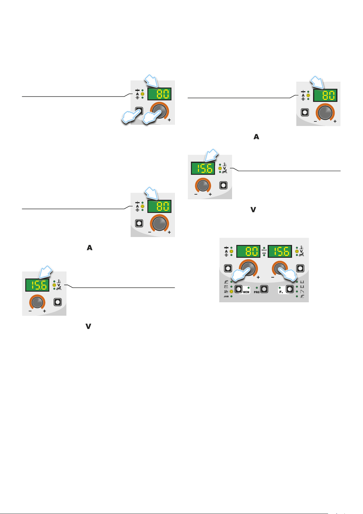
▪ PARAMETER DISPLAY screen - V▪ PARAMETER DISPLAY screen - A
■ PARAMETER SELECTION LED - A
When one of these LEDs is on it means that the corresponding
welding parameter has been selected.
■ PROGRAMME SELECTION LED
This LED will be lit only when the operator selects a welding process (in which there welding programmes present) and the relative associated programme.
■ PARAMETER DISPLAY screen - A
This Display shows the values / numbers (set or measured) of the
following parameters (if active):
• THICKNESS OF WELDED ITEM (
• WELDING CURRENT (
• WIRE SPEED (
).
• WELDING PROGRAM (
).
).
).
■ HOLD FUNCTION LED
Flashing, it indicates that the values of the parameters views on
the PARAMETER DISPLAY - A and V are respectively the values
that are set or measured at the conclusion of the last welding. The
LED flashes for 15 seconds consecutively before turning itself off or
until the moment that the operator varies any parameter by means
of the use of the handles.
■ WELDING PROCESS SELECTION LED
When one of these LEDs is on it means that the corresponding
welding process has been selected.
■ PARAMETER SELECTION LED - V
When one of these LEDs is on it means that the corresponding
welding parameter has been selected.
■ PARAMETER DISPLAY screen - V
This Display shows the values / numbers (set or measured) of the
following parameters (if active):
• ARC LENGTH ADJUSTMENT (
• WELDING VOLTAGE (
).
• ELECTRONIC INDUCTANCE (
).
).
■ JOB SAVING MEM LED
Flashes while saving a JOB.
■ Fx LED - SPECIAL FUNCTIONS
Switched on when special Fx parameters are displayed.
Viewing the software version installed
1) When the welding machine is working hold down the WELD-
ING PROCESS SELECTION key (T2) and WELDING MODE
SELECTION key (T3) together for about 2 consecutive seconds.
T2 T3
2) On both displays appears a running string that indicates the
VERSION OF THE SOFTWARE installed on the welder.
The rotation of one of the two ENCODER Knobs - A (E1) or
V (E2) by the operator during the display of the string version
software provokes the block (for 1 second), on both the displays, of the movement of the string itself.
E2E1
4

3) Ending viewing of the software version on the control panel
can come about in 2 different ways:
• Automatically: by waiting for the display time to elapse.
• Manually: by pushing any key.
Loading of the wire
In the MIG-MAG-PULSE-DOUBLE PULSE welding processes,
with the welder in operation, it is possible to load the wire inside
the torch, following this simple procedure:
• Keep the torch button held down.
• After a time of about 2 seconds, the wire begins to load itself at
a constant speed.
This operation is also indicated by a message made up of a nu-
•
merical value for the wire speed, followed by “LoAd” (see figure).
•
Rotate the ENCODER - A (E1) knob to change the wire loading speed.
• To finish the loading of the wire release the torch button.
WARNING: Changes to values are immediately activated (no further confirmation is required and they will be displayed immediately) or, at least they will become active the next time welding is
done. The operator can edit the functions (not the wire speed and
other parameters) when welding is underway and continue welding without having to exit the SPECIAL FUNCTIONS “Fx” menu.
E2E1
2) PROGRAM DEFAULT (dEF)
WARNING: If carried out, this operation resets the program
in use to the factory default settings.
E1
Special functions “Fx”
To access the SPECIAL FUNCTIONS “Fx” menu, hold the SPECIAL FUNCTIONS “Fx” key (T3) down for at least 3 consecutive
seconds. The Fx LED switches on.
T > 3 s
T3
The special functions allow the operator to regulate further parameters, operations and do partial resetting, and are operative, in a
different way, within each welding process.
Table 1 shows the special functions available. Details of the meaning of the columns are as follows:
• FUNCTION column: name of the special function.
DISPLAY column: symbol for the special function (message
•
shown in the PARAMETERS DISPLAY - A screen).
FACTORY column: Factory setting for the special function (mes-
•
sage shown in the PARAMETERS DISPLAY - V screen).
• RANGE column: regulation field for the special function.
The last two groups of columns, WELDING PROCESS and
•
MIG-MAG WELDING MODE indicate the welding process and
mode in which the special function can be selected. Example:
the SPOT WELD TIME function can be selected only when one
is welding in synergistic MIG-MAG-PULSE or manual SPOT
2T mode.
To carry out the reset of the settings / parameters, proceed in
the following manner:
• Rotate the ENCODER - A (E1) knob until both the displays
read dEF no (see figure).
E1
•
Rotate the ENCODER - V knob (E2) until the PARAMETERS DISPLAY - V screen (D2) reads YES.
D2
E2
• Hold the SAVE “MEM” key (T2) down for at least 2 consecutive seconds.
T ≥ 2 s
1) Rotate the ENCODER - A knob (E1) to select the SPECIAL
FUNCTION required. Rotate the ENCODER - V knob (E2) to
edit the VALUE for the special function selected.
T2
• The program in use has now been completed successfully.
To confirmation the above, the control panel of the welder
performs a short operation of MACHINE CHECK (all of the
LED stay lit simultaneously so as to verify their actual operation), the generator itself starts, having memorised the
new settings and is again ready to weld.
5

3) To exit the SPECIAL FUNCTIONS “Fx” menu, push and release the SPECIAL FUNCTIONS “Fx” (T3) key once.
T3
SETUP Menu
Hold the PRG key down for at least 3 seconds to open the SETUP menu, which provides access to various functions, which are
suitable for expert operators. For further information, see table 1.
FACTORY DEFAULT (FAC)
WARNING: The functions that can be selected depend on the
welding process activated. For this reason details of each function are given on the next pages, along with a description of the
WARNING: If carried out, this operation results in complete
resetting of all editable parameters to the factory settings (including cancellation of the JOBS).
welding processes.
Table 1
SETTINGS RANGE WELDING PROCESS MIG-MAG WELDING MODE
FUNCTION DISPLAY
FACTORY RANGE
MIG MAG / PULSE
MiG
dPL MAn
PLS
TIG MMA 2T 4T
Cra2TCra4TSpot 2TStitch
ADJUSTABLE FUNCTIONS “Fx” Fx > 3s
MIG-MAG process
PRE GAS PrG 0.1s (0.0 ÷ 2.0)s ● ● ● ● ● ● ● ● ●
STARTING SPEED Sts 0 -30 ÷ +30 ● ● ● ● ● ● ● ● ●
HOT START Hot 0 -30 ÷ +30 ● ● ● ● ● ● ● ● ●
CRATER
INITIAL CRATER
CRATER START CURRENT F08 20% (-50 ÷ +100)% ● ● ● ●
CRATER START SPEED F08 5.0m/min (1.5 ÷ 22.0)m/min ● ● ●
CRATER START VOLTAGE F09 15.0V (10.0 ÷ 26.0)V ● ● ●
CRATER START TIME F10 1.0s (0.0 ÷ 20.0)s ● ● ● ●
CRATER START SLOPE F 11 1.0s (0.0 ÷ 20.0)s ● ● ● ● ●
FINAL CRATER
CRATER END SLOPE F12 1.0s (0.0 ÷ 20.0)s ● ● ● ● ●
CRATER END CURRENT F13 -30 (-99 ÷ +50)% ● ● ● ●
CRATER END SPEED F13 5.0m/min (0.6 ÷ 22.0)m/min ● ● ●
CRATER END VOLTAGE F14 15.0V (10.0 ÷ 26.0)V ● ● ●
CRATER END TIME F15 0.0s (0.0 ÷ 20.0)s ● ● ● ●
SPOT WELD TIME F07 3.0s (0.1 ÷ 20.0)s ● ● ● ●
STITCH WELD
STITCH WELD TIME F05 1.0s (0.1 ÷ 20.0)s ● ● ● ●
STITCH WELD PAUSE F06 1.0s (0.1 ÷ 20.0)s ● ● ● ●
BURN BACK bUb 0 -30 ÷ +30 ● ● ● ● ● ● ● ● ●
POST GAS PoG 1.0s (0.0 ÷ 10.0)s ● ● ● ● ● ● ● ● ●
DUAL PULSE FUNCTIONS
DUAL PULSE DELTA CURRENT F23 40% (-50 ÷ +50)% ● ● ● ● ● ● ●
DUAL PULSE BALANCE F25 0% (-20 ÷ +20)% ● ● ● ● ● ● ●
DUAL PULSE FREQUENCY F26 1.5Hz (0.1 ÷ 2.5)Hz ● ● ● ● ● ● ●
TIG process
UP SLOPE F29 0.0s (0.0 ÷ 20.0)s ●
DOWN SLOPE F30 2.0s (0.0 ÷ 20.0)s ●
SWS VOLTAGE LIMIT F31 0 -30 ÷ 30 ●
MMA process
HOT START Hot 50 0 ÷ 100 ●
ARC FORCE ArC 50 0 ÷ 100 ●
PROGRAM DEFAULT dEF no no - YES ● ● ● ● ● ● ● ● ● ● ●
2T
SETUP (SEtUP) menu PRG > 3s
FACTORY DEFAULT FAC no no - YES ● ● ● ● ● ● ● ● ● ● ●
SPECIAL FUNCTIONS (SPC FnC) menu PRG > 3s
SAFETY CALIBRATION CODE SCC 7 0 ÷ 100 ● ● ● ● ● ● ● ● ●
MOTOR CALIBRATION Mot CAL
SPEED MOTOR 1 SM1 75.0 50.0 ÷ 99.9 ● ● ● ● ● ● ● ● ●
SPEED MOTOR 2 SM2 75.0 50.0 ÷ 99.9 ● ● ● ● ● ● ● ● ●
SPEED MOTOR 3 SM3 75.0 50.0 ÷ 99.9 ● ● ● ● ● ● ● ● ●
6

To carry out the reset of the settings / parameters, proceed in the
following manner:
1) Rotate the ENCODER - A (E1) knob until both the displays
read FAC no (see figure).
E1
2) Rotate the ENCODER - V knob (E2) until the PARAMETERS
DISPLAY - V screen (D2) readsYES.
D2
E2
SAFETY CALIBRATION CODE (SCC)
ATTENTION: This operation, if carryed on, optimizes the effi-
ciency of the welding circuit (only in MIG welding processes).
To set the length of the welding circuit (adjustable from 1 to 100
m) follow this procedure:
Rotate the ENCODER knob - A (E1) until obtaining on the PA-
•
RAMETER DISPLAY screen - A (D1) and the writing SCC.
• Rotate the ENCODER knob - V (E2) until obtaining on the PARAMETER DISPLAY screen - V (D2) the desired number.
CAUTION: The operation does not require confirmation!
CAUTION: The data inserted is valid for all the MIG welding pro-
cesses.
Example:
Length of cable mass 3 m.
Length of welding torch cable 3 m.
The overall length of the welding circuit is 6 m (6 is the number that
will therefore be inserted).
D1 D2
E2E1
3) Hold the SAVE “MEM” key (T2) down for at least 2 consecutive seconds.
T ≥ 2 s
T2
4) At this stage the total reset or factory default procedure has
been completed successfully (the parameters have been taken back to the factory values and any JOBS saved have been
deleted). To confirmation the above, the control panel of the
welder performs a short operation of MACHINE CHECK (all
of the LED stay lit simultaneously so as to verify their actual
operation), the generator itself starts, having memorised the
new settings and is again ready to weld.
Menu SPECIAL FUNCTIONS
From the SEtUP menu, push the PRG key (T5) for more than 3
seconds to access the SPECIAL FUNCTIONS menu, which provides access to additional functions that can only be managed
by an expert, responsible operator. The two displays (D1-D2) will
read SPC FnC.
D1 D2
MOTOR CALIBRATION (Mot CAL)
ATTENTION: This procedure allows you to calibrate the wire
speed (only in MIG welding processes).
Proceed as follows:
Rotate the ENCODER - A (E1) knob until the PARAMETER DIS-
•
PLAY - A (D1) screen reads Mot CAL.
D1
E1
• To open the CALIBRATION menu, push the PRG key (T3).
T3
• The procedure of calibration is carried out in 3 different phases:
1. Calibration parameter SM1 (MINIMUM SPEED)
Push and release the torch button, and then wait for the
T5
T ≥ 3 s
wire to stop automatically, and the End MiS message to appear. Measure (in cm) the dangling wire and insert the value
shown, in the software of the welder, by means of the rota-
7

tion of the ENCODER knob - V (E2) appearing on the PARAMETER DISPLAY screen - V (D2) is the desired value.
D1 D2
E2
MIG-MAG synergic / MIG pulse
/ double pulsed MIG
Start the welder by pressing the switch, located on the back panel, at the position I.
1 - WELDING PROCESS SELECTION
Select the MIG welding PROCESS this way:
1) Push the SELECT WELDING PROCESS (T2) key, even a
number of times if necessary, until the corresponding LED
switches on.
2. CalibrationparameterSM2(MEDIUMSPEED)
Then turn the ENCODER - A knob (E1) until the PARAM-
ETER DISPLAY - A screen (D1) shows the SM2 parameter. Push and release the torch button, and then wait for the
wire to stop automatically, and the End MiS message to appear. Measure (in cm) the dangling wire and insert the value
shown, in the software of the welder, by means of the rotation of the ENCODER knob - V (E2) appearing on the PARAMETER DISPLAY screen - V (D2) is the desired value.
D1 D2
E2E1
3. Calibration parameter SM3 (MAXIMUM SPEED)
Then turn the ENCODER - A knob (E1) until the PARAM-
ETER DISPLAY - A screen (D1) shows the SM3 parameter. Push and release the torch button, and then wait for the
wire to stop automatically, and the End MiS message to appear. Measure (in cm) the dangling wire and insert the value
shown, in the software of the welder, by means of the rotation of the ENCODER knob - V (E2) appearing on the PARAMETER DISPLAY screen - V (D2) is the desired value.
T2
2) Push the SELECT PROGRAM (T5) key. The corresponding
LED switches on.
T5
3A) To access the MIG-MAG synergic welding process: rotate the
ENCODER knob - A (E1) until obtaining on the PARAMETER
DISPLAY screen - A (D1) and the writing MiG.
E1
3B) To access the MIG pulse welding process: rotate the ENCOD-
ER knob - A (E1) until obtaining on the PARAMETER DISPLAY
screen - A (D1) and the writing PLS.
D1
D1 D2
E2E1
• At the end of the procedure, the software present in the welder
will immediately re-calculate the characteristic curve of the engine, rendering it suitable to use.
To exit from the CALIBRATION menu, press and release the
•
SAVE “MEM” key (T2).
T2
• To interrupt measuring, push the SAVE “MEM” (T2) Key.
E1
3C) To access the double pulsed MIG welding process: rotate the
ENCODER knob - A (E1) until obtaining on the PARAMETER
DISPLAY screen - A (D1) and the writing dPL.
D1
E1
8

2-SELECTIONOFWELDINGPROGRAMME
PROGRAM TABLE PRG
MIG-MAG-PULSE PROCESS
PROGRAM
NUMBER
000 Fe G3 Si-1 0.6 CO
001 Fe G3 Si-1 0.8 CO
002 Fe G3 Si-1 1.0 CO
010 Fe G3 Si-1 0.6 Ar/16-20%CO
011 Fe G3 Si-1 0.8 Ar/16-20%CO
012 Fe G3 Si-1 1.0 Ar/16-20%CO
015 Fe G3 Si-1 0,9 Ar/16-20%CO
051 Fe G3 Si-1 0.8 Ar/21-25%CO
055 Fe G3 Si-1 0.9 Ar/21-25%CO
195 Fe-rutil flux-cored E71T-GS 0.9 - ●
231 CrNi 308 G 19 9 LSI 0.8 Ar/2-3%CO
232 CrNi 308 G 19 9 LSI 1.0 Ar/2-3%CO
402 Al 99.9 S Al 1050 1.0 Ar ● ●
403 Al 99.9 S Al 1050 1.2 Ar ● ●
412 Al Mg 5 S Al 5356 1.0 Ar ● ●
413 Al Mg 5 S Al 5356 1.2 Ar ● ●
422 Al Si 5 S Al 4043A 1.0 Ar ● ●
423 Al Si 5 S Al 4043A 1.2 Ar ● ●
472 Al Si12 S Al 4047A 1.0 Ar ● ●
511 Cu Si 3 S CuSi3 0.8 Ar ● ●
512 Cu Si 3 S CuSi3 1.0 Ar ● ●
515 Cu Si 3 S CuSi3 0.9 Ar ● ●
911 Fe BD140 0.8 Ar/16-20%CO
951 Fe BD140 0.8 Ar/21-25%CO
PLS / dPL= Pulse version only
MATERIAL
TYPE CLASS MiG
WIRE Ø
(mm)
GAS
DISPLAYS
PLS
dPL
●
2
●
2
●
2
●
2
● ●
2
● ●
2
● ●
2
●
2
●
2
● ●
2
● ●
2
● ●
2
●
2
WARNING: This table is merely an example, the welding programs
can be updated and extended. See the table on the welding machine for the correct list of the programs available.
Select the welding PROGRAMME rotating ENCODER knob - V
(E2) until obtaining on the PARAMETER DISPLAY screen - V (D2)
the desired number.
D2
E2
3 - WELDING MODE SELECTION
Select the MODE of welding, pressing and releasing, even various
times if necessary, the WELDING MODE SELECTION key (T3)
until the corresponding LED lights up.
1 2 3 4 5 6
T3
1. TWO STROKE (2T)
2. FOUR STROKE (4T)
3. CRATER 2T
4. CRATER 4T
5. SPOT WELDING 2T
6. STITCH WELDING 2T
4 - SPECIAL FUNCTIONS “Fx” SELECTION
The SPECIAL FUNCTIONS “Fx” that are only available in the synergic MIG-MAG and pulsed / double pulsed MIG welding process
are shown below. For all the other explanations regarding this
menu make reference to the relative paragraph.
PRE GAS (PrG) - Provides an additional quantity of gas for a
•
defined time, before welding starts.
STARTING SPEED (StS) - Regulates the speed at which the
•
wire approaches the workpiece. The value indicated is a percentage variation in relation to the factory setting value.
• HOT START (Hot) - Regulates the current intensity for igniting
the welding arc. The value indicated is a percentage variation
in relation to the factory setting value.
CRATER START CURRENT (F08) - Sets the initial starting cur-
•
rent of the crater.
CRATER START TIME (F10) - This function defines the time
•
in which the current remains at the value of CRATER START
CURRENT.
CRATER START SLOPE (F11) - The time lapse for passing
•
from the CRATER START CURRENT level to the welding current level.
CRATERENDSLOPE(F12)- Time required to go from the
•
welding current level to the “CRATER END CURRENT” level.
CRATER END CURRENT (F13) - Sets the final welding cur-
•
rent of the crater.
CRATER END TIME (F15) - This function defines the time in
•
which the current remains at the value of CRATER END CURRENT.
• SPOT WELD TIME (F07) - The time during which spot welding
takes place after the arc is ignited, after which the arc is extinguished automatically.
STITCH WELD TIME (F05) - Time in which the welding in tracts
•
is performed after the ignition of the arch, after which the arch
switches off automatically.
STITCH WELD PAUSE (F06) - Time of pause between one
•
welding in tracts and another.
BURN BACK (bUb) - Regulates the length of the wire after weld-
•
ing. The value indicated is a percentage variation in relation to
the factory setting value. Higher numbers correspond to more
burning of the wire.
• POST GAS (PoG) - Provides an additional quantity of gas for a
defined time, after welding ends.
DUALPULSEDELTACURRENT(F23)- This function deter-
•
mines the positive or negative percentage variation in the peak
current, compared to the welding current set.
• DUALPULSEBALANCE(F25)- This function determines the
positive or negative percentage variation in the duration of the
peak current, compared to that of the welding current.
DUALPULSEFREQUENCY(F26)- This function determines
•
the variation in frequency (Hz) for double pulsed mode.
9

■ PROGRAM DEFAULT (dEF)
WARNING: If carried out, this operation resets the program
in use to the factory default settings.
To carry out the reset of the settings / parameters, proceed in the
following manner:
Rotate the ENCODER - A (E1) knob until both the displays read
•
dEF no (see figure).
E1
•
Rotate the ENCODER - V knob (E2) until the PARAMETERS
DISPLAY - V screen (D2) reads YES.
D2
D2
E2
T4
ARC LENGTH ADJUSTMENT
WELDING VOLTAGE (*)
ELECTRONIC INDUCTANCE
(*) The parameter is pre-set by means of synergy and can be changed
by varying the ARC LENGTH ADJUSTMENT parameter.
Example: ELECTRONIC INDUCTANCE
Press the PARAMETER SELECTION - V key (T4) until the LED
that corresponds to the ELECTRONIC INDUCTANCE switches
on. Turn the ENCODER - V knob (E2) to change the value shown
on the PARAMETER DISPLAY - V screen (D2).
6 - WELDING
During the welding the display shows:
• PARAMETER DISPLAY screen - A (D1)
THICKNESS OF WELDED ITEM
WELDING CURRENT
WIRE SPEED
D1
E2
•
Hold the SAVE “MEM” key (T2) down for at least 2 consecutive seconds.
T ≥ 2 s
T2
•
The program in use has now been completed successfully. To
confirmation the above, the control panel of the welder performs
a short operation of MACHINE CHECK (all of the LED stay lit
simultaneously so as to verify their actual operation), the generator itself starts, having memorised the new settings and is
again ready to weld.
5 - PRE-SETTING
Before welding it is possible to set the following parameters:
THICKNESS OF WELDED ITEM
WELDING CURRENT
WIRE SPEED
T1
D1
E1
Example: WIRE SPEED
Press the PARAMETER SELECTION - A key (T1) until the LED
that corresponds to the WIRE SPEED switches on. Turn the ENCODER - A knob (E1) to change the value shown on the PARAMETER DISPLAY - A screen (D1).
-
THICKNESS OF WELDED ITEM ( ): the value previously set.
WELDING CURRENT ( ): the measured value of the current
of what is being welded.
- WIRE SPEED (
): the value previously set.
• PARAMETER DISPLAY screen - V (D2)
D2
ARC LENGTH ADJUSTMENT
WELDING VOLTAGE
ELECTRONIC INDUCTANCE
- ARC LENGTH ADJUSTMENT ( ): the value previously set.
WELDING VOLTAGE ( ): the measured value of the voltage
of what is being welded.
- ELECTRONIC INDUCTANCE (
): the value previously set.
During the welding the operator can change the following parameters:
• THICKNESS OF WELDED ITEM (
• WELDING CURRENT (
• WIRE SPEED (
).
).
• ARC LENGTH ADJUSTMENT (
• ELECTRONIC INDUCTANCE (
).
).
).
• SPECIAL FUNCTIONS “Fx”.
WARNING: Remember that this process of welding is synergic
and for this reason the alteration of an individual parameter synergically also influences other parameters according to the predefined settings that are not modifiable!
10

7 - HOLD
This function automatically starts itself at the conclusion of every
welding operation and it is indicated to the operator by means of a
flashing light of the HOLD FUNCTION LED for a specific amount
of time.
Once the welding has been terminated, for about 15 seconds, both
the DISPLAYS should show the same values of the parameters
during the welding.
In this phase the displays show:
• PARAMETER DISPLAY screen - A (D1)
MIG-MAG manual
Start the welder by pressing the switch, located on the back panel, at the position I.
1 - WELDING PROCESS SELECTION
Select the MIG-MAG manual PROCESS of welding, pressing and
releasing, even various times if necessary, the WELDING PROCESS SELECTION key (T2) until the corresponding LED lights up.
THICKNESS OF WELDED ITEM
WELDING CURRENT
WIRE SPEED
-
THICKNESS OF WELDED ITEM ( ): the value previous-
D1
ly set.
- WELDING CURRENT (
- WIRE SPEED (
): the value previously set.
): the last current value measured.
• PARAMETER DISPLAY screen - V (D2)
D2
ARC LENGTH ADJUSTMENT
WELDING VOLTAGE
ELECTRONIC INDUCTANCE
- ARC LENGTH ADJUSTMENT ( ): the value previously set.
- WELDING VOLTAGE (
- ELECTRONIC INDUCTANCE (
): the last voltage value measured.
): the value previously set.
To interrupt the HOLD function and go back to the PRESETTING
phase before 15 seconds have passed, simply turn one of the two
ENCODER knobs (E1-E2).
T2
Push the SELECT PROGRAM (T5) key. The corresponding LED
switches on.
T5
To access the MIG-MAG synergic welding process: rotate the ENCODER knob - A (E1) until obtaining on the PARAMETER DISPLAY screen - A (D1) and the writing MAn.
E1
2-WELDINGMODESELECTION
Select the MODE of welding, pressing and releasing, even various
times if necessary, the WELDING MODE SELECTION key (T3)
until the corresponding LED lights up.
1 2 3 4 5 6
E2E1
The HOLD function can be terminated ahead of time even while
once again starting the welding.
Once 15 seconds have passed (HOLD FUNCTION) the control
panel goes back to the PRESETTING phase.
T3
1. TWO STROKE (2T)
2. FOUR STROKE (4T)
3. CRATER 2T
4. CRATER 4T
5. SPOT WELDING 2T
6. STITCH WELDING 2T
11

3 - SPECIAL FUNCTIONS “Fx” SELECTION
The SPECIAL FUNCTIONS “Fx” that are only available in the MIGMAG manual welding process are shown below. For all the other
explanations regarding this menu make reference to the relative
paragraph.
PRE GAS (PrG) - Provides an additional quantity of gas for a
•
defined time, before welding starts.
STARTING SPEED (StS) - Regulates the speed at which the
•
wire approaches the workpiece. The value indicated is a percentage variation in relation to the factory setting value.
• HOT START (HoT) - Regulates the current intensity for igniting
the welding arc. The value indicated is a percentage variation
in relation to the factory setting value.
CRATER START SPEED (F08) - Sets the initial speed of the
•
welding wire for the crater.
CRATER START VOLTAGE (F09) - Sets the initial welding volt-
•
age for the crater.
CRATER START TIME (F10) - This function defines the time
•
in which the current remains at the value of CRATER START
SPEED or CRATER START VOLTAGE.
CRATER START SLOPE (F11) - Time taken to go from the CRA-
•
TER START SPEED or CRATER START VOLTAGE level to the
welding speed or voltage level.
CRATERENDSLOPE(F12)- Time required to go from the
•
welding speed or voltage level to the CRATER END SPEED or
CRATER END VOLTAGE level.
• CRATER END SPEED (F13) - Sets the final speed of the weld-
ing wire for the crater.
CRATER END VOLTAGE (F14) - Sets the final welding volt-
•
age for the crater
CRATER END TIME (F15) - This function defines the time in
•
which the current remains at the value of CRATER END SPEED
or CRATER END VOLTAGE.
• SPOT WELD TIME (F07) - The time during which spot welding
takes place after the arc is ignited, after which the arc is extinguished automatically.
STITCH WELD TIME (F05) - Time in which the welding in tracts
•
is performed after the ignition of the arch, after which the arch
switches off automatically.
STITCH WELD PAUSE (F06) - Time of pause between one
•
welding in tracts and another.
BURN BACK (bUb) - Regulates the length of the wire after weld-
•
ing. The value indicated is a percentage variation in relation to
the factory setting value. Higher numbers correspond to more
burning of the wire.
• POST GAS (PoG) - Provides an additional quantity of gas for a
defined time, after welding ends.
■ PROGRAM DEFAULT (dEF)
WARNING: If carried out, this operation resets the program
in use to the factory default settings.
To carry out the reset of the settings / parameters, proceed in the
following manner:
Rotate the ENCODER - A (E1) knob until both the displays read
•
dEF no (see figure).
E1
•
Rotate the ENCODER - V knob (E2) until the PARAMETERS
DISPLAY - V screen (D2) reads YES.
D2
E2
•
Hold the SAVE “MEM” key (T2) down for at least 2 consecutive seconds.
T ≥ 2 s
T2
•
The program in use has now been completed successfully. To
confirmation the above, the control panel of the welder performs
a short operation of MACHINE CHECK (all of the LED stay lit
simultaneously so as to verify their actual operation), the generator itself starts, having memorised the new settings and is
again ready to weld.
4 - PRE-SETTING
Before welding it is possible to set the following parameters:
D1
WIRE SPEED
T1
E1
Example: WIRE SPEED
Press the PARAMETER SELECTION - A key (T1) until the LED
that corresponds to the WIRE SPEED switches on. Turn the ENCODER - A knob (E1) to change the value shown on the PARAMETER DISPLAY - A screen (D1).
12

D2
WELDING VOLTAGE
ELECTRONIC INDUCTANCE
E2
T4
Example: ELECTRONIC INDUCTANCE
Press the PARAMETER SELECTION - V key (T4) until the LED
that corresponds to the ELECTRONIC INDUCTANCE switches
on. Turn the ENCODER - V knob (E2) to change the value shown
on the PARAMETER DISPLAY - V screen (D2).
5 - WELDING
During the welding the display shows:
• PARAMETER DISPLAY screen - A (D1)
6 - HOLD
This function automatically starts itself at the conclusion of every
welding operation and it is indicated to the operator by means of a
flashing light of the HOLD FUNCTION LED for a specific amount
of time.
Once the welding has been terminated, for about 15 seconds, both
the DISPLAYS should show the same values of the parameters
during the welding.
In this phase the displays show:
• PARAMETER DISPLAY screen - A (D1)
D1
WELDING CURRENT
WIRE SPEED
D1
WELDING CURRENT
WIRE SPEED
-
WELDING CURRENT( ): the measured value of the current
of what is being welded.
- WIRE SPEED (
): the value previously set.
• PARAMETER DISPLAY screen - V (D2)
D2
WELDING VOLTAGE
ELECTRONIC INDUCTANCE
-
WELDING VOLTAGE ( ): the measured value of the voltage
of what is being welded.
- ELECTRONIC INDUCTANCE (
): the value previously set.
During the welding the operator can change the following parameters:
• WIRE SPEED (
• WELDING VOLTAGE (
• ELECTRONIC INDUCTANCE (
).
).
).
• SPECIAL FUNCTIONS “Fx”.
- WELDING CURRENT ( ): the last current value measured.
- WIRE SPEED (
): the value previously set.
• PARAMETER DISPLAY screen - V (D2)
D2
WELDING VOLTAGE
ELECTRONIC INDUCTANCE
- WELDING VOLTAGE ( ): the last voltage value measured.
- ELECTRONIC INDUCTANCE (
): the value previously set.
To interrupt the HOLD function and go back to the PRESETTING
phase before 15 seconds have passed, simply turn one of the two
ENCODER knobs (E1-E2).
E2E1
The HOLD function can be terminated ahead of time even while
once again starting the welding.
Once 15 seconds have passed (HOLD FUNCTION) the control
panel goes back to the PRESETTING phase.
13

Electrode (MMA)
3 - SPECIAL FUNCTIONS “Fx” SELECTION
Start the welder by pressing the switch, located on the back panel, at the position I.
1 - WELDING PROCESS SELECTION
Select the ELECTRODE PROCESS of welding (for welding with
“HOT START” and “ARC FORCE” devices, programmable by the
user) pressing and releasing, even various times if necessary, the
WELDING PROCESS SELECTION key (T2) until the corresponding LED lights up.
T2
Push the SELECT PROGRAM (T5) key. The corresponding LED
switches on.
T5
2-SELECTIONOFWELDINGPROGRAM
PROGRAM TABLE PRG
MMA PROCESS
MATERIAL
TYPE CLASS
Basic E7018 MMA bAS
Rutil E6013 MMA rUt
Cr-Ni E316L MMA Crn
DISPLAY
ADJUSTABLE FUNCTIONS “Fx” Fx > 3s
FUNCTION DISPLAY
HOT START Hot 50 0 ÷ 100
ARC FORCE ArC 50 0 ÷ 100
PROGRAM DEFAULT dEF no no - YES
SETTINGS RANGE
FACTORY RANGE
The SPECIAL FUNCTIONS “Fx” that are only available in the MMA
welding process are shown below. For all the other explanations
regarding this menu make reference to the relative paragraph.
HOT START (Hot) - At the start of the welding process it increas-
•
es the current, adjustable in percentage, reducing in such a way
the risk of low function at the start of the connection.
ARC FORCE (ArC) - During the welding process, it increases
•
the current in percentage, reducing in such a way the risk of fusing the electrode to the piece.
■ PROGRAM DEFAULT (dEF)
WARNING: If carried out, this operation resets the program
in use to the factory default settings.
To carry out the reset of the settings / parameters, proceed in the
following manner:
Rotate the ENCODER - A (E1) knob until both the displays read
•
dEF no (see figure).
E1
Select the welding PROGRAM by pushing the SELECT PROGRAM (T5) Key, and then rotate the ENCODER - V (E2) Knob
until the VIEW PARAMETERS - V (D2) display shows the program
required, chosen according to the type of electrode to be used (basic, rutile, and chrome-nickel).
D2
T1
T5
E2
•
Rotate the ENCODER - V knob (E2) until the PARAMETERS
DISPLAY - V screen (D2) reads YES.
D2
E2
14

•
Hold the SAVE “MEM” key (T2) down for at least 2 consecutive seconds.
T ≥ 2 s
T2
•
The program in use has now been completed successfully. To
confirmation the above, the control panel of the welder performs
a short operation of MACHINE CHECK (all of the LED stay lit
simultaneously so as to verify their actual operation), the generator itself starts, having memorised the new settings and is
again ready to weld.
4 - PRE-SETTING
Before welding it is possible to set the following parameters:
D1
WELDING CURRENT
T1
E1
Example: WELDING CURRENT
Press the PARAMETER SELECTION - A key (T1) until the LED
that corresponds to the WELDING CURRENT switches on. Turn
the ENCODER - A knob (E1) to change the value shown on the
PARAMETER DISPLAY - A screen (D1).
D2
WELDING VOLTAGE
HOT START
• PARAMETER DISPLAY screen - V (D2)
D2
WELDING VOLTAGE
HOT START
ARC FORCE
- HOT START ( ): the value previously set.
WELDING VOLTAGE ( ): the measured value of the voltage
of what is being welded.
- ARC FORCE (
): the value previously set.
During the welding the operator can change the following parameters:
• WELDING CURRENT (
• HOT START (
• ARC FORCE (
).
).
).
• SPECIAL FUNCTIONS “Fx” - FIRST LEVEL MENU.
6 - HOLD
This function automatically starts itself at the conclusion of every welding operation welding and it is indicated to the operator by
means of a flashing light of the HOLD FUNCTION LED for a specific amount of time. Once the welding has been terminated, for
about 15 seconds, both the DISPLAYS should show the same values of the parameters during the welding.
In this phase the displays show:
• PARAMETER DISPLAY screen - A (D1)
D1
WELDING CURRENT
ARC FORCE
E2
T4
Example: ARC FORCE
Press the PARAMETER SELECTION - V key (T4) until the LED
that corresponds to the ARC FORCE switches on. Turn the ENCODER - V knob (E2) to change the value shown on the PARAMETER DISPLAY - V screen (D2).
5 - WELDING
During the welding the display shows:
• PARAMETER DISPLAY screen - A (D1)
D1
WELDING CURRENT
-
WELDING CURRENT ( ):the measured value of the current
of what is being welded.
- WELDING CURRENT ( ): the last current value measured.
• PARAMETER DISPLAY screen - V (D2)
D2
WELDING VOLTAGE
HOT START
ARC FORCE
• HOT START ( ): the value previously set.
• WELDING VOLTAGE (
): the measured value of the last volt-
age of what is being previously welded.
• ARC FORCE (
): the value previously set.
To interrupt the HOLD function and go back to the PRESETTING
phase before 15 seconds have passed, simply turn one of the two
ENCODER (E1-E2) knobs.
E2E1
The HOLD function can be terminated ahead of time even once
again starting the welding.
Once 15 seconds have passed (HOLD FUNCTION) the control
panel goes back to the PRESETTING phase.
15

7 - ACTIVATING THE VRD DEVICE
The Voltage Reduction Device (VRD) is a safety device that reduces voltage. It prevents voltages forming on the output terminals that
may pose a danger to people. The factory settings do NOT set out
an active welding device during electrode welding.
If the operator wishes to weld in MMA using the VRD device (which
must be done with the welding machine switched off), they must:
1) Use a suitable screwdriver to unscrew the 4 screws that fix
the control panel to the welding machine.
2) Remove the “VRD” JUMPER on the DIGITAL INTERFACE
PCB (Fig. B).
3) Use a suitable screwdriver to tighten the 4 screws that fix the
control panel to the welding machine.
4) Start the welder by pressing the switch, located on the back
panel, at the position I.
After switching on, but with the machine at rest, the control panel
will show the VRD LED on in the colour GREEN and this means
that the device is active.
During the welding phase, this LED becomes RED, which however
does not indicate a malfunctioning of the welder but the fact that
the VRD device is in function and, at the conclusion of the welding
operation, the tension will be reduced within a maximum greatest
time of 0.3 seconds.
TIG with “Lift” striking
Start the welder by pressing the switch, located on the back panel, at the position I.
1 - WELDING PROCESS SELECTION
Select the TIG PROCESS of welding with “Lift” type starter for
welding without high frequency, pressing and releasing, also more
times if necessary, the WELDING PROCESS SELECTION key
(T2) until the corresponding LED lights.
FIG. B
■ PROGRAM DEFAULT (dEF)
WARNING: If carried out, this operation resets the program
in use to the factory default settings.
T2
2-SPECIALFUNCTIONS“Fx”SELECTION
ADJUSTABLE FUNCTIONS “Fx” Fx > 3s
FUNCTION DISPLAY
TIG process
UP SLOPE F29 0.0s (0.0 ÷ 20.0)s
DOWN SLOPE F30 2.0s (0.0 ÷ 20.0)s
SWS VOLTAGE LIMIT F31 0 -30 ÷ 30
PROGRAM DEFAULT dEF no no - YES
SETTINGS RANGE
FACTORY RANGE
The SPECIAL FUNCTIONS “Fx” that are only available in the
TIGLift welding process are shown below. For all the other explanations regarding this menu make reference to the relative paragraph.
UPSLOPE(F29)- Allows the joining of the WELDING CUR-
•
RENT to the INITIAL CURRENT.
DOWN SLOPE (F30) - Allows the joining of the WELDING CUR-
•
RENT to the FINAL CURRENT.
SWS VOLTAGE LIMIT (F31) - Regulates the voltage level for
•
automatic automatic extinguishing.
To carry out the reset of the settings / parameters, proceed in the
following manner:
Rotate the ENCODER - A (E1) knob until both the displays read
•
dEF no (see figure).
E1
•
Rotate the ENCODER - V knob (E2) until the PARAMETERS
DISPLAY - V screen (D2) reads YES.
D2
E2
•
Hold the SAVE “MEM” key (T2) down for at least 2 consecutive seconds.
T ≥ 2 s
T2
16
•
The program in use has now been completed successfully. To
confirmation the above, the control panel of the welder performs
a short operation of MACHINE CHECK (all of the LED stay lit
simultaneously so as to verify their actual operation), the generator itself starts, having memorised the new settings and is
again ready to weld.
3 - PRE-SETTING
Before welding it is possible to set the following parameters:
5 - HOLD
This function automatically starts itself at the conclusion of every welding operation welding and it is indicated to the operator by
means of a flashing light of the HOLD FUNCTION LED for a specific amount of time. Once the welding has been terminated, for
about 15 seconds, both the DISPLAYS should show the same values of the parameters during the welding.
In this phase the displays show:
• PARAMETER DISPLAY screen - A (D1)
D1
WELDING CURRENT
T1
E1
Example: WELDING CURRENT
Press the PARAMETER SELECTION - A key (T1) until the LED
that corresponds to the WELDING CURRENT switches on. Turn
the ENCODER - A knob (E1) to change the value shown on the
PARAMETER DISPLAY - A screen (D1).
4 - WELDING
During the welding the display shows:
• PARAMETER DISPLAY screen - A (D1)
D1
WELDING CURRENT
-
WELDING CURRENT ( ): the measured value of the current
of what is being welded.
• PARAMETER DISPLAY screen - V (D2)
D1
WELDING CURRENT
- WELDING CURRENT ( ): the last current value measured.
• PARAMETER DISPLAY screen - V (D2)
D2
WELDING VOLTAGE
-
WELDING VOLTAGE ( ): the measured value of the last voltage of what is being previously welded.
To interrupt the HOLD function and go back to the PRESETTING
phase before 15 seconds have passed, simply turn one of the two
ENCODER (E1-E2) knobs.
D2
WELDING VOLTAGE
-
WELDING VOLTAGE ( ): the measured value of the voltage
of what is being welded.
E2E1
The HOLD function can be terminated ahead of time even once
again starting the welding.
Once 15 seconds have passed (HOLD FUNCTION) the control
panel goes back to the PRESETTING phase.
17

JOB
1 - CREATING AND SAVING A JOB
This operation makes it possible to create and save welding settings (points) that can be called up by the operator at any time.
The control panel provides the possibility of saving a total of 99
JOBS spread over all the welding processes. There are not limits to the quantity or position of the points that can be saved for
each process!
When it leaves the factory the welding machine does not have
any JOBS saved in it and so the operator will find the control panel in this condition:
Having defined the parameters the operator needs to do their work
correctly, they can be saved by creating an AUTOMATIC WELDING POINT (JOB), proceeding as follows:
1) Hold the SAVE “MEM” key (T2) down for at least 2 consecutive seconds until both displays show the flashing wording
that represent the first AUTOMATIC WELDING POINT (JOB)
free and/or available to the operator that can be used for saving the data (e.g.: A01).
T2
To be able to choose another automatic welding point (JOB)
that is free for saving the data, simply turn one of the two ENCODER (E1-E2) knobs until you reach the required point.
2) Hold down the SAVE “MEM” (T2) Key down for at least 2 consecutive seconds to save JOB and automatically load the settings / parameters (including special functions) for the JOB just
saved.
3) To exit the JOB, press and release the WELDING PROCESS
SELECTION key (T2).
T2
2-JOBSELECTION
Select the JOB, pressing and releasing, even various times if necessary, the WELDING PROCESS SELECTION key (T2) until the
corresponding LED lights up.
T2
3 - PRE-SETTING / VIEWING MEMORISED JOB DATA
Since the parameters are memorised, within each JOB, viewable but not modifiable, the pre-setting phase does not exist, but
the operator can see and verify the settings, previously saved
and memorised, pressing and releasing the PARAMETER SELECTION key - A (T1) or in alternative the PARAMETER SELECTION key - V (T4).
The SPECIAL FUNCTIONS “Fx” Key (T3) contained within each
individual JOB can be viewed (but not modified) by simply keeping the SPECIAL FUNCTIONS “Fx” key (T3) pressed for a duration of about 2 seconds.
The display of the parameters (special functions included) lasts
only a few seconds, then the panel shows, in an automatic way,
the previous working condition.
E2E1
WARNING: If all the automatic welding points (JOBS) are occupied, the check automatically goes to the first automatic welding
point (JOB A01) as shown in the figure below).
T4T1
T3
4 - WELDING
During the welding the display shows the values, if possible measured, of the active parameters, based on the type of welding process, memorised within the selected JOB.
As already indicated, the parameters can be viewed by pressing
and releasing the PARAMETER SELECTION key - A (T1) or in alternative the PARAMETER SELECTION key - V (T4), while the
SPECIAL FUNCTIONS “Fx” key (T3) contained within each individual JOB can be viewed (but not modified) by simply keeping
the SPECIAL FUNCTIONS “Fx” key (T3) pressed for a duration
of about 3 seconds.
18

5 - HOLD
This function automatically starts itself at the conclusion of every
welding operation and it is indicated to the operator by means of a
flashing light of the HOLD FUNCTION LED for a specific amount
of time.
Once the welding has been terminated, for about 15 seconds, both
the DISPLAYS should show the same values of the parameters
during the welding.
To interrupt the HOLD function and go back to the PRESETTING
phase before 15 seconds have passed, simply turn one of the two
ENCODER (E1-E2) knobs.
E2E1
Error condition
This paragraph describes the error conditions that may arise on
the welding machine, the codes and messages shown on both operator interface displays, and the diagnoses for attempting to correct and resolve them.
In an “error condition” the operator’s interface uses both displays
to display:
▪ ERROR DESCRIPTION display▪ ERROR CONDITION display
The HOLD function can be terminated ahead of time even once
again starting the welding.
Once 15 seconds have passed (HOLD FUNCTION) the control
panel goes back to the PRESETTING phase.
6 - MODIFICATION AND OVERWRITING OF A
MEMORISED JOB
To edit and overwrite a JOB proceed as follows:
1) Select JOB, pressing and releasing, even various times if necessary, the WELDING PROCESS SELECTION key (T2) until
the corresponding LED lights up.
2) Select the individual JOB to modify and overwrite rotating the
ENCODER knob - V (E2).
3) Bring up and activate the JOB, loading its settings in the welding process it comes from, keeping the SAVE “MEM” key (T2)
pressed for a duration of about 2 seconds.
4) Acquire the parameters necessary for editing the JOB.
5) Hold the SAVE “MEM” key (T2) down for at least 2 consecutive seconds until both displays show the flashing wording
that represent the first AUTOMATIC WELDING POINT (JOB)
free and/or available to the operator that can be used for saving the data.
6) Rotate the ENCODER knob - V (E2) until identifying the individual JOB that will be overwritten.
7) Keep pressed, for at least 3 consecutive seconds, the SAVE
“MEM” key (T2) to confirm and make the operation effective.
7 - DELETING A JOB SAVED
In JOB mode, holding down the PARAMETER SELECTION - A
(T1) and PARAMETER SELECTION - V (T4) keys down simultaneously for about 5 seconds deletes the current automatic welding point.
T4T1
The control panel automatically goes to the first JOB saved or
reads “no JOB” is no JOBS have been saved.
Error
condition
Err T°C
Err E0.0
Err E0.1
Err E0.2
Err E0.3
Err E0.4
Err E1.0
Err E1.1
Err E1.3
Err E1.6
Err E1.7
Err E1.8
Err E1.9
Error
code
Error description and possible
diagnosis
THERMAL PROTECTION
The welding stops due to an
excessively high temperature
(thermostat activated).
Automatic reset error.
POWER SUPPLY FAILURE
NON automatic reset error.
This error can only arise when
switching on and not when the
welding equipment is working
normally.
OVER AND UNDER VOLTAGE
Automatic reset error.
OVER VOLTAGE
Automatic reset error.
UNDER VOLTAGE
Automatic reset error.
OVER CURRENT
NON automatic reset error.
Immediately contact technical
assistance dept.
CONFIG. FILE MISSING
NON automatic reset error.
Immediately contact technical
assistance dept.
USER FILE MISSING
NON automatic reset error.
Immediately contact technical
assistance dept.
CALIBRATION FILE MISSING
NON automatic reset error.
Immediately contact technical
assistance dept.
MMA DEFAULTS MISSING
NON automatic reset error.
Immediately contact technical
assistance dept.
DEFAULTS MISSING TIG
NON automatic reset error.
Immediately contact technical
assistance dept.
DEFAULTS MISSING MIG
NON automatic reset error.
Immediately contact technical
assistance dept.
WELDER DEFAULTS MISSING
NON automatic reset error.
Immediately contact technical
assistance dept.
(continued)
19

Error
condition
Err E2.0
Err E3.2
Err E3.4
Err E4.0
Err E4.1
Err E4.2
Err E4.3
Err E4.4
Err E5.0
Err E5.1
Err E5.3
Err E5.4
Error
code
Error description and possible
diagnosis
FILE SYSTEM ERROR
NON automatic reset error.
Immediately contact technical
assistance dept.
STICKING
This error is displayed when a
shortcircuit has been formed
between the machine’s output
terminals for more than 1.2 seconds.
NON automatic reset error.
To remove the error state, eliminate
the short circuit so that the voltage
on the torch goes above the
threshold value again. At this stage
the error condition disappears and
the welding machine goes back to
the mode prior to the sticking. If the
torch trigger is still pushed, it must be
released and pressed again to begin
welding again.
SCC ERROR
NON automatic reset error.
LAST SETUP NOT VALID
NON automatic reset error.
Immediately contact technical
assistance dept.
JOBS WRONG
NON automatic reset error.
Immediately contact technical
assistance dept.
MIG SYN SPECIAL FUNCTION “Fx”
WRONG
NON automatic reset error.
Immediately contact technical
assistance dept.
MIG MAN SPECIAL FUNCTION “Fx”
WRONG
NON automatic reset error.
Immediately contact technical
assistance dept.
SPECIAL “Fx” PULSED MIG
FUNCTIONS NOT VALID
NON automatic reset error.
Immediately contact technical
assistance dept.
MIG PROGRAMS MISSING
NON automatic reset error.
Immediately contact technical
assistance dept.
NO PULSED MIG WELDING
PROGRAMS
NON automatic reset error.
Immediately contact technical
assistance dept.
PROGRAMS MISSING
NON automatic reset error.
Immediately contact technical
assistance dept.
NO WELDING PROGRAMS
NON automatic reset error.
Immediately contact technical
assistance dept.
(continued)
Error
condition
AUT ADJ
The table includes 2 types of errors:
• Automatic reset error: Once the alarm condition has been re-
solved the welding machine starts working again and the operator can weld again!
NON automatic reset error: To remove the alarm status and
•
reinstate correct operation of the machine, the welding equipment must be switched off.
The machine will then be working again and the operator can
weld again!
PLEASE NOTE: If, when switching on, the error status presents itself again, immediately contact the Technical Assistance Department.
This is necessary so that our technical assistance dept (that must
be contacted each time the error messages appear on the
welding machine’s operator interface) is able to resolve the
problems more easily and as quickly as possible, thanks to the re
ports by the user, and also because, in the meantime the welding
machine does not allow the operator to do their work.
Error
code
Error description and possible
diagnosis
POWER LIMITATION
This alarm appears if the power limit
is exceeded. The alarm alternates
with the standard display every 1.5
seconds, despite which the machine
continues to weld, supplying limited
power, but complying with the values
shown on the data plate.
-
20

CEA COSTRUZIONI ELETTROMECCANICHE ANNETTONI S.p.A.
C.so E. Filiberto, 27 - 23900 LECCO - ITALY
Cas. Post. (P.O. BOX) 205
Tel. +39 0341 22322 - Fax +39 0341 422646
cea@ceaweld.com
www.ceaweld.com
 Loading...