

CEA RAINBOW HF Series, RAINBOW HF 201, RAINBOW HF 182 PRO, RAINBOW HF 202 PRO Operator's Manual

EN
Operator’s manual
READ CAREFULLY
201 • 182 PRO • 202 PR O
RAINBOW HF
CEA COSTRUZIONI ELETTROMECCANICHE ANNETTONI S.p.A.
C.so E. Filiberto, 27 - 23900 Lecco - Italy
Tel. ++39.0341.22322 - Fax ++39.0341.422646
Cas. Post. (P.O.BOX) 205
e-mail: cea@ceaweld.com - web: www.ceaweld.com
1020HB47C-EN-03/2016 SN - ZC xxxxxx

EN
ENGLISH
Introduction 2
Description 2
Features 2
Usage limits (IEC 60974-1) 3
Technical data 3
How to lift up the machine 3
Open the packaging 3
Serial number 3
Installation 3
Connection to the electrical supply 4
Instructions for use 4
TIG welding 4
Electrode welding (MMA) 6
Maintenance 6
Optional 6
The pointing out of any difficulties
and their elimination 7
Procedure for welder assembly and disassembly 7
Digital interface PCB replacement 7
Meaning of graphic symbols on machine 8
Wiring diagram 8
Introduction
Thank you for buying our product.
In order to get the best performance out of the plant and ensure the
maximum lifespan of its parts, the use and maintenance instructions contained in this manual must be read and strictly complied
with, as well as the safety instructions contained in the rele-
vant folder. If repairs to the plant are required, we recommend that
our clients contact our service centre workshops, as they have the
necessary equipment and personnel that are specifically trained
and constantly updated.
All our machines and equipment are constantly developed and so
changes may be made in terms of their construction and features.
For further information on our products or to contact CEA, go to a
CEA authorised dealer or to CEA’s website at www.ceaweld.com.
Description
RAINBOW 201 HF - 182 HF PRO - 202 HF PRO with digital control
represents the very latest evolution in direct current weld generators with INVERTER technology. This powerful 100 KHz generator,
based on the latest generation IGBT, fitted with a planar transformer, makes it possible to TIG weld any metal except for aluminium
and its alloys.
RAINBOW 201 HF - 182 HF PRO - 202 HF PRO, also excellent for
electrode welding, with its lightness and compactness and first-rate
welding characteristics, is ideal for using for maintenance, erection and light steel structural works.
Features
Main features are:
• Innovative and compact design.
• Compact size and light weight for easy transportation.
• Load-bearing structure with panels made of impact-resistant fibre.
• Robust handle integrated into the chassis.
• Control panel protected against accidental impact.
Sloping front control panel, easy to read and adjust and highly
•
visible from any direction.
• IP 23 S protection class and dust-proof electronic components,
thanks to the innovative “Tunnel” fan cooling system, allow their
use in the toughest work environments.
• Two control panels are available:
-
Rainbow 201 HF with an RW21 “basic version” control panel.
-
Rainbow 182 HF Pro - 202 HF Pro with an RW22 “complete
version” control panel.
Digital control, regulation and monitoring of all welding param-
•
eters.
• Digital display for pre-setting welding parameters.
Digital ammeter is standard fittings, with pre-setting of welding
•
current and saving of the latest value (Hold function).
• Feature that makes it possible to save and call up personalised
welding programs (only adjustable with the RW22 control panel).
• Self-diagnosis device.
• Overheating thermostatic protection.
Automatic compensation for mains voltage fluctuations within
•
±20%.
• Safety barrier against excess voltage from mains.
•
Electromagnetic disturbance is reduced due to high frequency
being involved only during the arc ignition phase.
• “Energy Saving” function that starts ventilation of the generator
only when necessary.
This generator also conforms to all the standards and directives
•
in force in the European Community.
• TIG
- Excellent TIG welding characteristics.
High frequency arc striking of TIG welding, precise and effi-
cient even from long distance.
- Using special TIG torches allows remote adjustment of welding current directly from the torch.
Standard built-in pulsation with provision for entering the SYN
Pulse function (only adjustable with the RW22 control panel).
2

• MMA
The VRD (Voltage Reduction Device) can be activated, which
reduces voltages to below 12 V, which means that the welding machine can be used in ambient conditions in which there
is a high electrical risk, thereby providing maximum operator safety.
Arc Force to select the best dynamic characteristics of the
welding arc (only adjustable with the RW22 control panel).
-
Hot Start to improve ignition with particularly difficult electrodes
(only adjustable with the RW22 control panel).
- Anti-sticking function to avoid the electrodes sticking.
Usage limits (IEC 60974-1)
The use of a welder is typically discontinuous, in that it is made up
of effective work periods (welding) and rest periods (for the positioning of parts, the replacement of wire and underflushing operations etc. This welder is dimensioned to supply a I2 max nominal
current in complete safety for a period of work of X% of the total usage time. The regulations in force establish the total usage
time to be 10 minutes. The work cycle is considered to be X% of
this period of time. If the permitted work cycle time is exceeded,
an overheat cut-off occurs to protect the components around the
welder from dangerous overheating. Activation of thermal protection is signaled by “t° C” flashing on control panel display (for further information see the RW21 / RW22 control panel manual). After
several minutes the overheat cut-off rearms automatically and the
welder is ready for use again.
Technical data
The general technical data of the system are summarized in table 1.
How to lift up the machine
The weld machine has a strong handle all in one with the frame,
used for transporting the machine manually only.
NOTE: These hoisting and transportation devices conform to European standards. Do not use other hoisting and transportation
systems.
Open the packaging
Upon receiving the system:
Remove the welding generator and all relevant accessories-
•
components from their packaging.
•
Check that the weld machine is in good condition, if not report
any problems immediately to the seller-distributor.
Make sure all ventilation grilles are open and that no foreign bod-
•
ies are blocking the air circulation.
Serial number
The welding machine’s serial number is shown on the unit’s data
plate.
The serial number provides the key to tracing the production lot
applicable to the product. The serial number may be essential with
ordering spare parts or planning maintenance.
Installation
The installation site for the system must be carefully chosen in order to ensure its satisfactory and safe use. The user is responsible for the installation and use of the system in accordance with
the producer’s instructions contained in this manual. Before installing the system the user must take into consideration the potential
electromagnetic problems in the work area. In particular, we suggest that you should avoid installing the system close to:
• Signalling, control and telephone cables.
• Radio and television transmitters and receivers.
• Computers and control and measurement instruments.
• Security and protection instruments.
Table 1
Model
Single-phase power supply 50/60 Hz V 1~230 ±20% 1~230 ±20% 1~230 ±20%
Mains supply: Z
Power input @ I
Delayed fuse (I
Power factor / cosφ 0,67 / 0,99 0,67 / 0,99 0,67 / 0,99
Maximum efficiency degree η 0,82 0,84 0,82 0,84 0,82 0,84
Open circuit voltage V889088
Current range A 5÷200 5÷160 5÷180 5÷160 5÷200 5÷160
Duty cycle @ 100% (40°C) A 120 110 110 80 120 110
Duty cycle @ 60% (40°C) A 140 130 130 100 140 130
Duty cycle @ X% (40°C) A 200 (25%) 160 (30%) 180 (25%) 160 (20%) 200 (25%) 160 (30%)
Standards
Insulation class IP 23 S IP 23 S IP 23 S
Protection class FFF
Dimensions
Weight kg 7,5 7,5 7,5
(*) Mains supply Z
WARNING: This equipment does not comply with EN/IEC 61000-3-12. If it is connected to a public low voltage system, it is the responsibility
of the installer or user of the equipment to ensure, by consultation with the distribution network operator if necessary, that the equipment may
be connected.
(*) Ω 0,19 0,19 0,19
max
Max kVA 8,5 9,0 6,9 8,3 8,5 9,0
2
@ 100%) A201620
2
mm 390-300-135 390-300-135 390-300-135
: maximum impedance value allowed for the grid according to the EN/IEC 61000-3-11 standard.
max
RAINBOW 201 HF RAINBOW 182 HF PRO RAINBOW 202 HF PRO
TIG DC MMA TIG DC MMA TIG DC MMA
IEC 60974-1 • IEC 60974-3 • IEC 60974-10
3

Table 2
Model
Power input @ I
Delayed fuse (I
Duty cycle @ X% (40°C) A 200 (25%)* 160 (30%)* 180 (25%)* 160 (20%)* 200 (25%)* 160 (30%)*
Supply connection cable
Length
Section
Earth cable
Section mm
* Factor of efficiency
Persons fitted with pace-makers, hearing aids and similar equipment must consult their doctor before going near a machine in operation. The environment in which the equipment is installed must
be suitable for the casing’s protection level. This system is cooled
by means of the forced circulation of air, and must therefore be
placed in such a way that the air may be easily sucked in and expelled through the apertures made in the frame.
The welding unit is characterised by the following levels:
•
Protection level IP 23 S indicates that the equipment can be used
both indoors and outdoors.
Use class means that the equipment can be used in condi-
•
tions subject to heightened electrical shock.
Max kVA 8,5 9,0 6,9 8,3 8,5 9,0
2
@ 100%) A201620
2
m
mm
RAINBOW 201 HF RAINBOW 182 HF PRO RAINBOW 202 HF PRO
TIG DC MMA TIG DC MMA TIG DC MMA
2
2
2,5
2,5
25 25 25
2,5
2,5
2,5
2,5
1
3
Connection to the electrical supply
Before connecting the welder to the electrical supply, check
that the machine’s plate rating corresponds to the supply voltage and frequency and that the line switch of the welder is in
the “O” position.
Connection to the power supply must be carried out using the tripolar cable supplied with the system, of which:
2 conducting wires are needed for connecting the machine to
•
the supply.
• The third, which is YELLOW GREEN in colour is used for making the “EARTH” connection.
Connect a suitable load of normalised plug (2P + e) to the
power cable and provide for an electrical socket complete
with fuses or an automatic switch. The earth terminal must
be connected to the earth conducting wire (YELLOW-GREEN)
of the supply.
Table 2 shows the recommended load values for retardant supply fuses.
NOTE 1: Any extensions to the power cable must be of a suitable
diameter, and absolutely not of a smaller diameter than the special cable supplied with the machine.
NOTE 2: It is not advisable to plug up the welder to motor-driven generators, as they are known to supply an unstable voltage.
Instructions for use
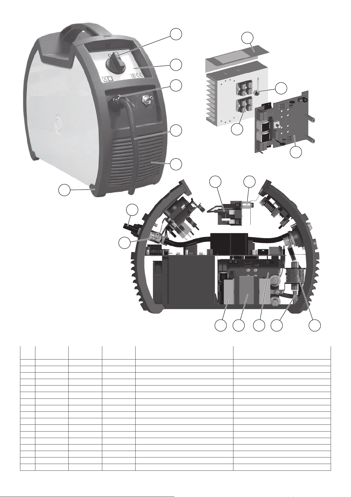
COMMAND AND CONTROL UNITS (Fig. A)
Pos. 1 RW21 / RW22 command and control panel.
Pos. 2 Positive pole quick connection.
Pos. 3 Fast coupling TIG torch gas tube.
Pos. 4 TIG weld auxiliary control connector (torch button, re-
Pos. 5 Negative pole quick connection.
Pos. 6 Power supply switch.
In the “O” position the welder is off.
Pos. 7 Mains cable.
Pos. 8 Weld gas inlet coupling.
mote controlpedal, etc.).
2
4
5
6
8
7
TIG welding
In the TIG process welding is achieved by melting the two metal
pieces to be joined, with the possible addition of material from the
outside, using an arc ignited by a tungsten electrode. The molten
bath and the electrode are protected by and inert gas (e.g. Argon,
and a flow rate of around 8-14 litres per minute). If necessary, to
complete the welded joint, suitable additional material is added.
FIG. A
4

The type of additional material and welding current are determined
according to the type of thickness of the base material, the shape
of the joint, and the position of the weld.
1) Connecting the welding cables (Fig. B):
• Connect the gas hose to the Argon cylinder.
• With the machine switched off:
Connect the ground cable to the snap-on connector
marked + (positive).
-
Connect the relative ground clamp to the workpiece or
to the workpiece support in an area free of rust, paint,
grease, etc..
Connect the TIG torch power cable to the snap-on con-
nector marked - (negative).
-
Connect the torch gas tube to the connection (Pos. 3,
Fig. A).
Insert the torch button connector in the 6 poles holder
-
2) Switch the welding machine on by moving the power supply
3) Make the adjustments and select the parameters on the con-
(Pos. 4, Fig. A).
switch to I (Pos. 6, Fig. A).
trol panel (for further information see the RW21 / RW22 control panel manual).
TIG WELDING WITH “Lift” TYPE STRIKING
4a) Open the gas cylinder and flow regulator (8-14 l/min).
5a) Put the electrode at the point at which welding is to begin, put
the TIG torch at an angle so that the edge of the gas nozzle
is not on top of the piece to be welded, keeping contact between the point of the electrode and the piece to be welded
(Fig. C-1).
6a) Press the torch button.
7a) The “Lift” function strikes the arc when the TIG torch electrode
comes into contact with the workpiece and is then removed
(Fig. C-2)
8a) Carry out TIG welding (Fig. C-3).
To end welding:
•
Lift the torch slowly, at a certain point the welding current
decreases, and then stop.
The welding machine follows an automatic down slope
•
along with extinguishing of the arc.
9a) When finished welding remember to shut off the gas cylinder.
TIG WELDING WITH HIGH FREQUENCY STRIKING (HF)
4b) Open the gas cylinder and flow regulator (8-14 l/min).
5b) Put the electrode at the point at which welding is to begin, put
the TIG torch at an angle so that the edge of the gas nozzle is
not on top of the piece to be welded, keeping a 2-3 mm gap
between the point of the electrode and the piece to be weld-
ed (Fig. D-1).
6b) Press the torch button.
7b) The voltaic arc strikes even without contact between the TIG
torch electrode and the workpiece (Fig. D-2).
8b) To continue welding put the torch back in its normal position
(Fig. D-3).
9b) When finished welding remember to shut off the gas cylinder.
IMPORTANT: The high frequency switches off automatically after switching on.
FIG. B
PART TO BE WELDED
The part to be welded must always be connected to ground in order to reduce electromagnetic emission. Much attention must be
afforded so that the ground connection of the part to be welded
does not increase the risk of accident to the user or the risk of damage to other electric equipment. When it is necessary to connect
the part to be welded to ground, you should make a direct connection between the part and the ground shaft. In those countries
in which such a connection is not allowed, connect the part to be
welded to ground using suitable capacitors, in compliance with the
national regulations.
WELDING PARAMETERS
Table 3 shows the currents to use with the respective electrodes
for TIG welding. This input is not absolute but is for your guidance
only; read the electrode manufacturers’ instructions for a specific
choice. The diameter of the electrode to use is directly proportional to the current being used for welding.
Table 3
Ø ELECTRODE (mm) CURRENT (A)
1,2
1,6
2,4
3,2
4,0
Before use, sharpen the tungsten electrode, forming a tip about
1,5 times its diameter.
10 ÷ 80
70 ÷ 150
140 ÷ 250
225 ÷ 400
300 ÷ 500
FIG. C FIG. D
2000HA73
2000HA72
5
Į
FIG. E
If the electrode comes into contact with the workpiece, the point must be formed again.
The point on the electrode must be shaped as
shown in the figure.
α (°) CURRENT (A)
30
60 ÷ 90
90 ÷ 120
0 ÷ 30
30 ÷ 120
120 ÷ 250

Electrode welding (MMA)
The welding electrode is used to weld most metals (various types
steel, etc.),for which rutilic and basic electrodes are used.
1) Connecting the welding cables (Fig. F):
Disconnect the machine from the mains power supply and con-
nect the welding cables to the output terminals (Positive and
Negative) of the welding machine, attaching them to the clamp
and ground with the polarity specified for the type of electrode
being used (Fig. F). Always follow the electrode manufacturer’s instructions. The welding cables must be as short as possible, they must be near to one another, positioned at or near
floor level. Do not touch the electrode clamp and the ground
clamp simultaneously.
2) Switch the welding machine on by moving the power supply
switch to I (Pos. 6, Fig. A).
3) Make the adjustments and select the parameters on the control panel (for further information see the RW21 / RW22 control panel manual).
4) Carry out welding by moving the torch to the workpiece. Strike
the arc (press the electrode quickly against the metal and then
lift it) to melt the electrode, the coating of which forms a protective residue. Then continue welding by moving the electrode
from left to right, inclining it by about 60° compared with the
metal in relation to the direction of welding.
PART TO BE WELDED
The part to be welded must always be connected to ground in order to reduce electromagnetic emission. Much attention must be
afforded so that the ground connection of the part to be welded
does not increase the risk of accident to the user or the risk of damage to other electric equipment. When it is necessary to connect
the part to be welded to ground, you should make a direct connection between the part and the ground shaft. In those countries
in which such a connection is not allowed, connect the part to be
welded to ground using suitable capacitors, in compliance with the
national regulations.
WELDING PARAMETERS
Table 4 shows some general indications for the choice of electrode, based on the thickness of the parts to be welded. The values of current to use are shown in table 5 with the respective
electrodes for the welding of common steels and low-grade alloys. These data have no absolute value and are indicative data
only. For a precise choice follow the instructions provided by the
electrode manufacturer.
Table 4
WELDING THICKNESS (mm) Ø ELECTRODE (mm)
1,5 ÷ 3
3 ÷ 5
5 ÷ 12
≥ 12
Ø ELECTRODE (mm) CURRENT (A)
1,6
2
2,5
3,2
4
The current to be used depends on the welding positions and the
type of joint, and it increases according to the thickness and dimensions of the part.
The current intensity to be used for the different types of welding,
within the field of regulation shown in table 5 is:
• High for plane, frontal plane and vertical upwards welding.
• Medium for overhead welding.
Low for vertical downwards welding and for joining small pre-
•
heated pieces.
2
2,5
3,2
4
Table 5
30 ÷ 60
40 ÷ 75
60 ÷ 110
95 ÷ 140
140 ÷ 190
FIG. F
A fairly approximate indication of the average current to use in
the welding of electrodes for ordinary steel is given by the following formula:
I = 50 × (Øe - 1)
Where:
I = intensity of the welding current
Øe = electrode diameter
Example:
For electrode diameter 4 mm
I = 50 × (4 - 1) = 50 × 3 = 150A
Maintenance
ATTENTION: Before carrying out any inspection of the inside of
the generator, disconnect the system from the supply.
SPARE PARTS
Original spare parts have been specially designed for our equipment. The use of non-original spare parts may cause variations in
performance or reduce the foreseen level of safety.
We decline all responsibility for the use of non-original spare parts.
GENERATOR
As these systems are completely static, proceed as follow:
Periodic removal of accumulated dirt and dust from the inside
•
of the generator, using compressed air. Do not aim the air jet
directly onto the electrical components, in order to avoid damaging them.
• Make periodical inspections in order to individuate worn cables
or loose connections that are the cause of overheating.
Optional
RAINBOW 201 HF / 182 HF PRO / 202 HF PRO generators can
be fitted with various remote control devices and accessories.
The remote controls can be only used in the 2-STROKE and
4-STROKE welding modes.
MANUAL REMOTE CONTROL CD6
WARNING: When using the machine for TIG welding it is OBLIGA-
TORY to use the kit for simultaneously use – CEA code n° 460056.
Weld current can be measured at a distance by connecting up this
control. The display will show the previous maximum weld current value set on the welder. The remote control will adjust welding current from the minimum to this value (for further information
see the RW21 / RW22 control panel manual). Just turn the adjustment knob on the welder to change the maximum output value.
6

FIG. G
FOOT SWITCH PSR7
The foot switch replaces the torch button and the welding current
setting knob. The display will show the previous maximum weld
current value set on the welder. The pedal will adjust the welding
current from the minimum to this value (for further information see
the RW21 / RW22 control panel manual). Just turn the adjustment
knob on the welder to change the maximum output value.
NOTE:
To use the pedal control correctly, set the “welding mode” to
•
2-STROKE and then the welding parameters SLOPE UP time
to 0 sec., SLOPE DOWN time to 0 sec.
• When using the machine for TIG welding the operator can use
the torch button to start the weld and the pedal to regulate the
welding current remotely, provided the simultaneous use kit
(code CEA n° 460056) is used.
Procedure for welder assembly
and disassembly
Proceed as follows (Fig. G):
• Unscrew the 4 screws holding the front and back panels.
• Unscrew the 2 screws holding the handle.
• Proceed the other way round to re-assemble the welder.
Digital interface PCB replacement
Proceed as follows:
• Unscrew the 4 screws fastening the front rack panel.
• Remove the adjustment knob.
• Extract wiring connectors from digital interface PCB.
• Remove digital interface PCB by lifting it out of its supports.
• Proceed vice versa to assemble new digital interface PCB.
AIR AND/OR WATER-COOLED TORCH UP/ DOWN
The up/down torch replaces the current setting knob on the front
of the welder. Press right (+) and left (-) button to adjust the active parameter. With this kind of torch, it is also possible to scroll
the saved programmes by pressing the two (+) and (-) buttons.
NOTE: The value shown on the display during welding represents
the effective current output with all types of control.
The digital control unit of the generator is fitted with a control recognition device which allows it to identify which device is connected and take action accordingly. To allow the command recognition
device to work correctly, connect (with the machine switched off)
the required accessory to the relative connector and then switch
on the welding machine with the on/off switch.
NOTE: It is not possible to memorize or open programmes
when the remote controls are connected (except for the torch
with UP/DOWN commands).
When the machine is doing a programmed weld, if a remote control command is activated (and the self-recognition procedure is
carried out), it exits programming automatically.
The pointing out of any difficulties
and their elimination
The supply line is attributed with the cause of the most common
difficulties. In the case of breakdown, proceed as follows:
1) Check the value of the supply voltage
2) Check that the power cable is perfectly connected to the plug
and the supply switch
3) Check that the power fuses are not burned out or loose
4) Check whether the following are defective:
• The switch that supplies the machine.
• The plug socket in the wall.
• The generator switch.
NOTE: Given the required technical skills necessary for the repair
of the generator, in case of breakdown we advise you to contact
skilled personnel or our technical service department.
7

Meaning of graphic symbols on machine
Power supply switch
System for use in environments with increased
risk of electroshock
Product suitable for free circulation in the European Community
Danger! High voltage
Grounding
Positive pole snap-in connector
Negative pole snap-in connector
Connector for the remote control
Warning!
Fast coupling TIG torch gas tube
Before using the equipment you should carefully
read the instructions included in this manual
MMA welding
TIG welding
Special disposal
Wiring diagram
•1 •2 •3 •4 •5 •6 •7 •8 •9
C11-12-13-24 CD 6 CT D1-2 D8-12 DD DW ED EVG
•10 •11 •12 •13 •14 •15 •16 •17 •18 •19
FPP FPS IL MV PD PSR 7 PT Q1-2-3-4 RF SF
•20 •21 •22 •23 •24 •25 •26 •27
SHF S-INT DIG S-INV SS THS THF TORCH TORCH UP/DOWN
•28 •29
TP UP
Key to the electrical diagram
•1 Capacitors •2 Remote control •3 TIG torch connector •4 Secondary diode
•5 Primary circuit rectifier •6 Digital display •7 DOWN button •8 Encoder •9
Gas solenoid valve •10 Pedal control potentiometer •11 Microswitch •12
Mains switch •13 Fan •14 Remote current potentiometer •15 Pedal control •16 TIG torch button •17 Primary IGBT circuit •18 Membrane keyboard
•19 EMC filter PCB •20 High frequency (HF) PCB •21 Digital interface PCB
•22 Primary Inverter PCB •23 Secondary circuit PCB •24 Secondary circuit
thermostat •25 HF transformer •26 TIG torch •27 Up / Down TIG torch •28
Main transformer •29 UP button
Colour key
Ar Orange
Az Sky Blue
Bc White
Bl Blue
Gg Grey
Gl Yellow
GV Yellow-Green
Mr Brown
Nr Black
Ro Pink
Rs Red
Vd Green
Vl Violet
8

2101AB72/B
PRO
Ip
PULSE
I1
HOT
START
p
T
f
b
Ib
T
I2
CYCLE
ARC
FORCE
SET
PROG
CYCLE
RAINBOW
PULSE
202 HF
SYN
FAST
SLOW
201 HF
RAINBOW
9

IT
Lista ricambi
LEGGERE ATTENT AMENTE
EN
Spare parts list
READ CAREFULLY
201 • 182 PRO • 202 PR O
RAINBOW HF
CEA COSTRUZIONI ELETTROMECCANICHE ANNETT ONI S.p.A.
C.so E. Filiberto, 27 - 23900 Lecco - Italy
Tel. ++39.0341.22322 - Fax ++39.0341.422646
Cas. Post. (P.O.BOX) 205
e-mail: cea@ceaweld.com - web: www.ceaweld.com

IT
Lista ricambi
EN
Spare parts list
1
2 3 5
4
6
7
8
9
10
11
12
13
14
16
RAINBOW
Pos.
10 423134 423134 423134 Dado fissaggio connettore torcia Torch connector nut
1 1 352464 352464 352464 Pannello frontale Front panel
12 352384 352384 352384 Alette di aerazione Ventilation grill
13
14 454150 454150 454150 Encoder Encoder
15 423102 423102 423102 Dado encoder Encoder nut
16 424027 424027 424027 Distanziale scheda frontale Rack pcb spacer
201 HF
1 352551 352551 352551 Pannello laterale Side panel
2 438205 438205 438205 Maniglia Handle
3 365850 365850 365850 Piastrina connessione tracolla Shoulder bag connection
- - 447865
4
- 447868 -
5 447864 - - Tastiera a membrana Rainbow 201 HF Membrane keyboard Rainbow 201 HF
6 438849 438849 438849 Manopola di regolazione encoder Encoder adjustment knob
7 403635 403635 403635 Attacco rapido gas Gas quick connection
8 40361 1 403611 403611 Attacco rapido Quick connection
9 419002 419002 419002 Connettore torcia 6 poli 6 poles torch connector
377173 - - Scheda frontale Rainbow 201 HF Rack pcb Rainbow 201 HF
- 377173B - Scheda frontale Rainbow 182 HF Pro Rack pcb Rainbow 182 HF Pro
- - 377173A Scheda frontale Rainbow 202 HF Pro Rack pcb Rainbow 202 HF Pro
RAINBOW
182 HF PRO
RAINBOW
202 HF PRO
Descrizione Description
Tastiera a membrana
Rainbow 202 HF Pro
Tastiera a membrana
Rainbow 182 HF Pro
15
Membrane keyboard
Rainbow 202 HF Pro
Membrane keyboard
Rainbow 182 HF Pro
2
17
18
31
21
29
30
19
20
12
32
33
26
22 23
RAINBOW
Pos.
17 438710 438710 438710 Manopola interruttore Switch knob
18 467025 467025 467025 Adesivo pannello posteriore Rear panel sticker
19 427895 427895 427895 Pressacavo Main cable clamp
20 235996 235996 235996 Cavo linea Main cable
21 352383 352383 352383 Pannello posteriore Rear panel
22 377172 377172 377172 Scheda spinterometro Spark gap pcb
23 424009 424009 424009 Distanziale scheda spinterometro Spark gap pcb spacer
24 239987 239987 239987 Trasformatore HF HF transformer
25 424159 424159 424159 Distanziale trasformatore HF HF transformer spacer
26 377175 377175 377175 Scheda secondaria Secondary pcb
27 463220 463220 463220 Staffa fissaggio trasformatore Transformer clamp
28 481420 481420 481420 Trasformatore principale Main transformer
29 425933 425933 425933 Elettrovalvola gas Gas solenoid valve
30 485040 485040 485040 Tubo gas Gas hose
31 466900 466900 466900 Isolatore dissipatore Heatsink insulation
32 478786 478786 478786 Termostato Thermostat
33 423236 423236 423236 Diodo secondario Secondary diode
201 HF
RAINBOW
182 HF PRO
RAINBOW
202 HF PRO
Descrizione Description
3
2425262728

40
34 35
373839
36
39
41
42
37
RAINBOW
Pos.
34 377174 377174 377174 Scheda alimentazione / EMC Power supply / EMC pcb
35 435375 435375 435375 Interruttore principale Main switch
36 444510 444510 444510 Ventilatore Fan
37 427251 427251 427251 Ancoraggio dissipatori primari Plastic primary heatsink clamp
38 352475 352475 352475 Basamento in fibra Plastic base
39 240492 240492 240492 Complessivo inverter di potenza Power inverter assembly
40 413396 413396 413396 Cablaggio elettrico ausiliario Electric auxiliary wiring
41 286020 286020 286020 IGBT primari Primary IGBT
42 455510 455510 455510 Raddrizzatore primario Primary rectifier
201 HF
RAINBOW
182 HF PRO
RAINBOW
202 HF PRO
Descrizione Description
IT
Ordinazione dei pezzi di ricambio
Per la richiesta di pezzi di ricambio indicare chiaramente:
1) Il numero di codice del particolare
2) Il nome dell'impianto
3) La tensione e la frequenza che rileverete dalla targhetta
dei dati posta sull’impianto
4) Il numero di matricola
ESEMPIO
N° 2 pezzi, codice n. 423236 - per l’impianto RAINBOW 201
HF - 230 V - 50/60 Hz - Matricola n° ........................................
EN
Ordering spare parts
To ask for spare parts clearly state:
1) The code number of the piece
2) The name of the machine
3) The voltage and frequency read on the rating plate
4) The serial number of the machine
EXAMPLE
N. 2 pieces code n. 423236 - for RAINBOW 201 HF - 230 V -
50/60 Hz - Serial number .......................................................
4

EN
Operator’s manual
READ CAREFULLY
RW 21
CEA COSTRUZIONI ELETTROMECCANICHE ANNETT ONI S.p.A.
C.so E. Filiberto, 27 - 23900 Lecco - Italy
Tel. ++39.0341.22322 - Fax ++39.0341.422646
Cas. Post. (P.O.BOX) 205
e-mail: cea@ceaweld.com - web: www.ceaweld.com

EN
ENGLISH
Introduction 2
Control panel 2
Displaying the software version installed 3
Electrode welding (MMA) 3
TIG welding 4
TIG welding with the SPOT WELDING function on 4
TIG welding - Welding parameters 5
Activating the VRD device 5
Auxiliary functions 6
Factory default 6
Error and protection conditions 6
Introduction
This manual describes the functions on and how to use the following control panels:
• RW 21
Control panel
DISPLA Y WELDING MODE
WELDING PARAMETERS
RAINBOW
201 HF
VRD
WELDING PROCESS
ENCODER KNOB
■ DISPLAY
Displays the selections made using the various keys (with corresponding LED on or flashing) and regulated using the ENCODER KNOB.
■ WELDING PROCESS
The RAINBOW HF welding machine offers 3 TIG/Electrode welding processes. Each time the button is pushed, the welding machine switches to select the welding process indicated by the LED
that stays lit, in the following order:
L1 TIG with HF ignition
L2 TIG with “Lift” type ignition
L3 ELECTRODE (MMA)
■ VRD
The Voltage Reduction Device (VRD) is a safety device that reduces the voltage. It prevents voltages forming on the output terminals that may pose a danger to people.
Two-tone LED (off - red - green) indicates enabling of the VRD
device.
The standard, preset settings for the firm do not activate the VRD
function on the welding machine and so this LED is normally off.
To activate the VRD device, see the relevant paragraph.
L1L3L2
2

■ WELDING MODE
The RAINBOW welding machine offers 3 welding modes. Each
time the button is pushed, the welding machine switches to select the welding mode indicated by the LED that stays lit, in the
following order:
L4 2 STROKES
L5L6L4
L5 4 STROKES
L6 SPOT WELDING
L4 2 STROKES
TIG welding takes place as follows:
1 (A)
I
SLOPE UP SLOPE DOWN
WELDING CURRENT (I1)
ST ANDARD TIG WELDING CONFIGURATION
When one of the 2 TIG welding processes available on the welding
machine is activated, this allows you to select the following welding parameters, based on which LED is flashing:
L7 PRINCIP AL welding CURRENT I1
L8 PRE-GAS duration
L9 SLOPE UP duration
L10 SLOPE DOWN duration
L11 POST-GAS duration
L7 L10 L11L8 L9
T3
POST GAS
t (sec)PRE-GAS
2000HC22/A
L5 4 STROKES
TIG welding takes place as follows:
I1 (A)
SLOPE UP SLOPE DOWN
WELDING CURRENT (I1)
POST GAS
t (sec)PRE-GAS
2000HC22/A
NOTE: Welding only begins when the torch button is pushed.
L6 SPOT WELDING
This can be used by pushing the torch button to spot weld for a preset period of time (in seconds) at the end of which the arc switches off automatically.
■ ENCODER KNOB
This is used to regulate and change the welding parameters, according to which LED is switched on and the value shown on the
DISPLA Y, which is necessary for the machine to work correctly.
Displaying the software
version installed
The RAINBOW HF are fitted with a digital control with software on
board defined in the factory . This software is subject to continuous
evolution and improvement. The software is identified by a specific number that can be viewed on the DISPLA Y (D) as follows:
1) With the welding machine switched on, press and hold down
the WELDING MODE button (T1).
2) The DISPLAY (D) shows the type of version of software installed.
3) To exit, push and release the WELDING MODE button (T1).
D
RAINBOW
201 HF
T1
W
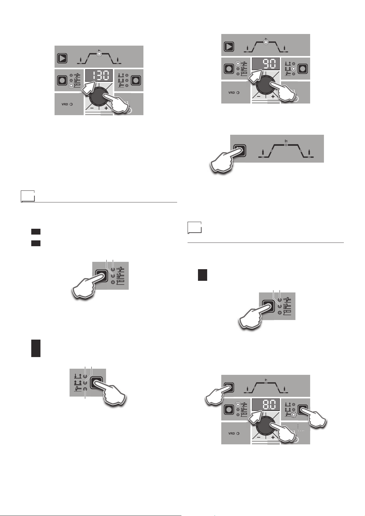
Electrode welding (MMA)
1) Start the welding machine by turning the power supply switch
to position I.
2) WELDING PROCESS SELECTION
Push the WELDING PROCESS SELECTION key (T2) to se-
lect the ELECTRODE welding processes.
■ WELDING PARAMETERS
Each time the button is pushed, the welding machine selects the
next function according to the machine configuration, the welding
process, the welding mode, etc...
T o exit welding parameter programming, hold the T3 button down
for about 1 second.
ST ANDARD MMA WELDING CONFIGURATION
When using the electrode welding process, this allows you to select
the following welding parameters, based on which LED is flashing:
L7 HOT START
L7
T3
T2
D
RAINBOW
201 HF
3
3) Turn the ENCODER KNOB (E) until the DISPLAY shows the
B
01
B
01
01
B
01
01
01
PRINCIP AL welding CURRENT V ALUE at which you wish to
weld, in relation to the diameter of the electrode you are using.
D
RAINBOW
RAIN
201 HF
E
The following functions are pre-set automatically in the facto-
ry:
HOT START - Increases the welding current automatical-
•
ly at the start of the welding process, thereby reducing the
risk of poor melting of the electrode at the start of the joint.
•
ARC FORCE - Automatically regulates the dynamic characteristics of the arc.
4) Once the all the selections/regulations indicated above have
been made, welding can begin.
5) During the welding process the DISPLAY (D) shows the real
Amps (A) at which the operator is actually welding.
TIG welding
1) Start the welding machine by turning the power supply switch
to position I.
2) Press the WELDING PROCESS SELECTION Key (T2) and
select:
L1 a TIG “HF” welding process for direct current TIG weld-
ing with high frequency ignition.
L2 a TIG “Lift” welding process for direct current TIG “Lift”
type welding without high frequency .
L1L2
T2
4) Turn the ENCODER KNOB (E) until the DISPLAY (D) shows
the CURRENT VALUE at which you wish to weld.
D
RAINBOW
RAIN
201 HF
E
5) By pushing the WELDING PARAMETERS SELECTION (T3)
key a number of times it is possible to set the various TIG
WELDING P ARAMETERS (see the “TIG Welding” paragraph
- WELDING P ARAMETERS).
T3
6) To exit welding parameter programming, hold the T3 button
down for about 1 second.
7) Once the all the selections/regulations indicated above have
been made, welding can begin.
8) During the welding process the DISPLAY shows the real Amps
(A) at which the operator is actually welding.
TIG welding with the SPOT
WELDING function on
1) Start the welding machine by turning the power supply switch
to position I.
2) Press the WELDING PROCESS SELECTION Key (T2) and
select one of the welding machine’s 2 TIG processes:
L1 TIG with HF ignition
L2 TIG with “Lift” type ignition
L1L2
WARNING: The “Lift” ignition current is created by pushing
the torch button only after having touched the workpiece with
the electrode.
3) Press the WELDING MODE SELECTION Key (T1) and go to
one of the 3 options available:
L4 2T
L5 4T
L6 SPOT WELD
L5L6L4
T1
T2
3) Press the WELDING MODE SELECTION Key (T1) and go to
one of the SPOT WELDING function.
4) Press and release the WELDING P ARAMETERS SELECTION
Key (T3) until the SPOT WELD LED starts flashing.
5) Rotate the ENCODER knob (E) to set the SPOT WELDING
time required (0,1÷10,0 sec).
T3
D
RAINBOW
RAIN
201 HF
E
T1
W
4

6) By pushing the WELDING PARAMETERS SELECTION (T3)
key a number of times it is possible to set the various TIG
WELDING P ARAMETERS (see the “TIG Welding” paragraph
- WELDING P ARAMETERS).
T3
7) To exit welding parameter programming, hold the T3 button
down for about 1 second.
8) Once the all the selections/regulations indicated above have
been made, welding can begin.
9) During the welding process the DISPLAY shows the real Amps
(A) at which the operator is actually welding.
TIG welding - W elding parameters
Press the WELDING P ARAMETERS SELECTION Key (T3) a number of times to set:
L7 L10 L11L8 L9
T3
Activating the VRD device
To activate the VRD device, which must be done when the welding machine is switched off:
1) Use a suitable screwdriver to unscrew the 4 screws that fix
the control panel to the welding machine.
2) Position JUMPER W1 on the DIGITAL INTERFACE BOARD
in the correct position, following the instructions given in Figure A.
3) Use a suitable screwdriver to tighten the 4 screws that fix the
control panel to the welding machine.
4) Start the welding machine by pushing the switch on the rear
panel to position I.
L8 PRE-GAS duration (0,05 ÷ 1,00 sec)
WARNING: This CANNOT be programmed when the TIG with
“Lift” type ignition welding processes is active.
L9 SLOPE UP duration (0,0 ÷ 5,0 sec)
L7 PRINCIP AL welding CURRENT I1 (5 ÷ 200 A)
L10 SLOPE DOWN duration (0,0 ÷ 8,0 sec)
L11 POST GAS duration (1 ÷ 25,0 sec)
WARNING: When the post-gas LED flashes and the LED I
1 is on
at the same time, this means that the welding machine is in the
post-gas stage.
T o exit the setting phase, hold the WELDING PARAMETERS SELECTION key (T3) down for about 1 second.
FIG. A
2000HC23
When the control panel switches on the VRD LED will come on
and will be GREEN, which means that the VRD function is on.
To “deactivate” the VRD device and therefore start to weld, follow
this simple procedure: First touch the workpiece with the electrode, then detach it and ignite the arc within a MAX of 0,3 sec-
onds, otherwise if this time is exceeded the VRD device starts and
prevents welding.
During welding the VRD LED turns RED, which does not indicate
any malfunction on the welding machine, but that the VRD device
has been deactivated to allow welding.
5

Auxiliary functions
“Energy saving”
This function manages correct functioning of the cooling fan that
only runs when strictly necessary , that is:
• F AN MOTOR - The fan is activated when:
-
During welding or for a certain period of time after this is finished.
-
When the thermostat intervenes or for a certain period of time
after it has just been reset.
Factory default
WARNING: This operation results in complete resetting of all pa-
rameters to the factory settings.
To reset the settings, you must:
• With the machine switched on, push and hold down the WELDING MODE (T1) and SELECT WELDING PROCESS (T2) buttons simultaneously for about 3 seconds.
When all the LEDs switch on at the same time, reinstatement
•
of the welding machine’s software to its default settings is complete.
• The message on the DISPLAY (D) reads 80.
• The reset procedure has now been completed successfully.
t > 3 s t > 3 s
T2
D
RAINBOW
201 HF
T1
W
All of this is necessary to allow our technical assistance department (which must be contacted each time error messages
appear on the equipment’s operator interface) to resolve problems more easily , as quickly as possible and thanks to the user’s
reports, also because, in the meantime the machine will not allow
the operator to do their work.
T able 1
Display Diagnosis
POWER SUPPLY FAILURE
E0.0
NON automatic reset error.
This error can only arise when switching on and not
when the welding plant is working normally .
USER FILE MISSING
E1.0
NON automatic reset error.
Immediately contact technical assistance dept.
CONFIGURA TION FILE MISSING
E1.1
NON automatic reset error.
Immediately contact technical assistance dept.
INTERNAL MEMORY ERROR
E1.2
NON automatic reset error.
Immediately contact technical assistance dept.
CALIBRA TION FILE MISSING
E1.3
NON automatic reset error.
Immediately contact technical assistance dept.
THERMAL PROTECTION
t°C
The welding stops due to an excessively high
temperature (thermostat activated).
Automatic reset error.
WARNING: The welding machine has a built-in electronic protective device to deal with fluctuations in mains voltage that
switches the machine off automatically (voltage exceeding
300 V), without indicating any type of error or warning message for the operator. Subsequently it starts functioning again
automatically when the voltage has dropped to below the value indicated above.
Error and protection conditions
D
RAINBOW
201 HF
The equipment is protected against problems and if any arise the
DISPLA Y shows fixed or flashing (error code) messages (depending on the type of error) that serve to inform the operator that a fault
has occurred in the equipment (see table 1).
The table provides a summary of all the error conditions that may
arise on the equipment and, if possible, what the operator must
do to attempt to resolve the problem.
Automatic reset error: once the alarm condition has been resolved the equipment starts working again and the operator can
weld again!
PLEASE NOTE: If the fault persists look for the cause of the
fault and contact our technical assistance department if necessary.
6

CEA COSTRUZIONI ELETTROMECCANICHE ANNETTONI S.p.A.
C.so E. Filiberto, 27 - 23900 LECCO - ITALY
Cas. Post. (P.O. BOX) 205
Tel. +39 0341 22322 - Fax +39 0341 422646
cea@ceaweld.com
www.ceaweld.com
ISO 9001: 2008
 Loading...