


EN
Operator’s manual
READ CAREFULLY
1020HA91E-EN-04/2017 SN - JD xxxxxx
MATRIX AC/DC • AC/DC R
2200 • 3000
CEA COSTRUZIONI ELETTROMECCANICHE ANNETTONI S.p.A.
C.so E. Filiberto, 27 - 23900 Lecco - Italy
Tel. ++39.0341.22322 - Fax ++39.0341.422646
Cas. Post. (P.O.BOX) 205
E-mail: cea@ceaweld.com - web: www.ceaweld.com

2
ENGLISH
EN
Introduction 2
Description 2
Features 2
Usage limits (IEC 60974-1) 3
Technical data 3
Open the packaging 4
Installation 4
Connection to the electrical supply 4
Instructions for use 4
Interfacing accessories (optional) 5
TIG welding 6
Electrode welding (MMA) 7
Maintenance 7
Optional 8
The pointing out of any difficulties and their elimination 8
Digital interface PCB replacement 8
Meaning of graphic symbols on machine 9
Adjustment of electronic circuit board 9
Wiring diagram (MATRIX 2200 AC/DC) 10
Wiring diagram (MATRIX 3000 AC/DC - AC/DC R) 12
Key to the electrical diagram 14
Colour key 14
Description
MATRIX 2200 AC/DC
Powerful, compact, and light weight, the MATRIX 2200 AC/DC
units represent the most innovative, high performance, and technically advanced single-phase inverter generators for TIG welding to be found. The PFC (Power Factor Correction) device fitted
optimises absorption of energy from the mains, means that these
high power generators can be connected to power supply systems
with 16A fuses without any problem. The user friendly digital control and advanced functions ensure complete stability of all welding
parameters, guaranteeing high quality TIG welding for all metals,
aluminium, and its alloys, as well as MMA welding with any type
of electrode. The MATRIX 2200 AC/DC units are the ideal solution for all professional welding applications and for maintenance
work that calls for power and portability.
MATRIX 3000 AC/DC - MATRIX 3000 AC/DC R
Using the most modern IGBT based inverter technology, the threephase TIG generator with high frequency MATRIX 3000 AC/DC
or 3000 AC/DC R ignition, comes with an innovative digital control
for all welding parameters.
Technologically cutting-edge, robust, easy to use with both direct
and alternating current, fitted with high potential digital control,
this generator can be used for high quality TIG welding of all metals including aluminium and alloys. This means that the machine
is particularly suitable for specific uses in industry and the maintenance sector.
It also guarantees excellent performance for MMA welding, even
when using particularly difficult cellulosic and basic electrodes.
Features
The characteristics found in all welding machines in the MATRIX
AC/DC range are:
• Innovative and compact design.
• Compact size and light weight for easy transportation.
• Metallic main structure with shock-proof plastic front panel.
• Protective visor on the control panel.
• Robust handle integrated into the chassis.
•
Digital control, regulation and monitoring of all welding parameters.
• Digital display for pre-setting welding parameters.
• Digital ammeters and voltmeters are standard fittings, with presetting of welding current and saving of the latest value (Holdfunction).
•
coldTACK function in TIG HF DC. Innovative spot welding de
vice to achieve precise and safe joining with a minimal thermal
input. “Multi-coldTACK” function grants cold spotting in a rapid
sequence, thus further widening the benefits of the single spot.
Thanks to “Perfect-Point” function, coldTACK allows to obtain
the most precise spot positioning.
• Feature that makes it possible to save and call up personalised
welding programs.
• Self-diagnosis device.
• Overheating thermostatic protection.
•
Automatic compensation for mains voltage fluctuations within
±20%.
• Safety barrier against excess voltage from mains.
•
Electromagnetic disturbance is reduced due to high frequency
being involved only during the arc ignition phase.
•
“Energy Saving” function to operate the power source cooling
fan andthe torch water cooling only when necessary.
• Low absorbed current consumption.
•
This generator also conforms to all the standards and directives
in force in the European Community.
Introduction
Thank you for buying our product.
In order to get the best performance out of the plant and ensure the
maximum lifespan of its parts, the use and maintenance instructions contained in this manual must be read and strictly complied
with, as well as the safety instructions contained in the rele-
vant folder. If repairs to the plant are required, we recommend that
our clients contact our service centre workshops, as they have the
necessary equipment and personnel that are specifically trained
and constantly updated.
All our machines and equipment are constantly developed and so
changes may be made in terms of their construction and features.

3
• TIG
- Excellent TIG welding characteristics.
-
High frequency arc striking of TIG welding, precise and efficient even from long distance.
- Using special TIG torches allows remote adjustment of welding current directly from the torch.
-
The diameter of the electrode used is set to allow greater control of the ignition and dynamics of the arc.
-
Standard built-in pulsation (from 0,5 to 2000 Hz) with provision for entering the SYN Pulse function.
-
Square, mixed, sinusoidal, or triangular wave shape selector.
-
Square welding wave frequency balancing / regulation and
“Balance Plus”.
• MMA
-
The VRD (Voltage Reduction Device) can be activated, which
reduces voltages to below 12 V, which means that the welding machine can be used in ambient conditions in which there
is a high electrical risk, thereby providing maximum operator safety.
-
“Arc Force” adjustable to select the best dynamic characteristics for the welding arc.
- “Hot Start” adjustable to improve ignition with particularly difficult electrodes.
- Anti-sticking function to avoid the electrodes sticking.
MATRIX 2200 AC/DC
•
The PFC device makes the wave form of the current absorbed sinusoidal, which results in no harmonic disturbance on the mains
and optimisation of absorption, which allows you to use the generator’s full power with a 16 A fuse, as well as ensuring greater protection of the welding machine against fluctuations in the
power supply voltage.
MATRIX 3000 AC/DC R
• Suitable for use on all robotic systems.
•
Optional “RoboMAT 1” interface that handles all process start/
stop signals, regulation of the principal welding parameters, and
also acts as a flexible, efficient interfacing system that meetsall
Analogue / Digital connection requirements.
Usage limits (IEC 60974-1)
The use of a welder is typically discontinuous, in that it is made up
of effective work periods (welding) and rest periods (for the positioning of parts, the replacement of wire and underflushing operations etc. This welder is dimensioned to supply a I2 max nominal
current in complete safety for a period of work of X% of the total usage time. The regulations in force establish the total usage
time to be 10 minutes. The work cycle is considered to be X% of
this period of time. If the permitted work cycle time is exceeded,
an overheat cut-off occurs to protect the components around the
welder from dangerous overheating. Activation of thermal protection is signaled by “t° C” flashing on control panel display (for further information see the MTA control panel manual). After several
minutes the overheat cut-off rearms automatically and the welder
is ready for use again.
Technical data
The general technical data of the system are summarized in table 1.
Table 1
Model
MATRIX 2200 AC/DC
MATRIX 3000 AC/DC
MATRIX 3000 AC/DC R
TIG MMA TIG MMA
Power supply 50/60 Hz V 1~ 230 ±20% 3~ 400 ±20%
Power supply: Z
max
Ω (*) 0,092
Input power @ I
2
Max kVA 6,5 7,0 9,6
Delayed fuse (I
2
@ 100%) A 16 10
Power factor / cosφ 0,99 / 0,99 0,95 / 0,99
Efficiency degree η 0,77 0,76 0,81
Open circuit voltage V 100 100
Current range A 5÷220 10÷180 5÷300 10÷250
Duty cycle @ 100% (40°C) A 140 120 210 190
Duty cycle @ 60% (40°C) A 180 150 250 220
Duty cycle @ X% (40°C) A 220 (30%) 180 (30%) 300 (35%) 250 (40%)
Usable electrodes mm 1,2÷2,4 1,6÷4,0 1,2÷4,0 1,6÷5,0
Standards
IEC 60974-1 • IEC 60974-3 • IEC 60974-10
IEC 60974-1 • IEC 60974-3 • IEC 60974-10
Protection class IP 23 S IP 23 S
Insulation class F F
Dimensions
mm 465 - 390 - 185 495 - 390 - 185
Weight kg 15,5 19
IMPORTANT:
These systems, tested in accordance with the requirements of the EN/IEC 61000-3-3 standard, satisfy the requirements laid down by the EN/
IEC 61000-3-11 standard.
MATRIX 2200 AC/DC
(*) This equipment meets the requirements laid down in the EN/IEC 61000-3-12 standard on harmonic currents.
MATRIX 3000 AC/DC - AC/DC R
This equipment complies with EN/IEC 61000-3-12 provided that the maximum permissible system impedance Z
max
is less than or equal to 0,092
at the interface point between the user’s supply and the public system. It is the responsibility of the installer or user of the equipment to ensure,
by consultation with the distribution network operator if necessary, that the equipment is connected only to a supply with maximum permissible
system impedance Z
max
less than or equal to 0,092.

4
How to lift up the machine
The weld machine has a strong handle all in one with the frame,
used for transporting the machine manually only.
NOTE: These hoisting and transportation devices conform to European standards. Do not use other hoisting and transportation
systems.
Open the packaging
The system essentially consists of:
• MATRIX AC/DC or AC/DC R weld unit.
• Separately:
- Welding TIG torches (optional).
- Neck strap (optional MATRIX 2200 AC/DC).
- Ground cable, complete with rapid coupling (optional).
- Coolant unit for welding torch (optional).
- trolley for transportation (optional).
-
“RoboMAT 1” analogue / digital robot interface (optional this
interface must only be used for automatic / robotised equipments).
-
Generator interconnection cable - robot interface (optional
- this interface must only be used for automatic / robotised
equipments).
Upon receiving the system:
•
Remove the welding generator and all relevant accessoriescomponents from their packaging.
•
Check that the weld machine is in good condition, if not report
any problems immediately to the seller-distributor.
•
Make sure all ventilation grilles are open and that no foreign bodies are blocking the air circulation.
Installation
The installation site for the system must be carefully chosen in order to ensure its satisfactory and safe use. The user is responsible for the installation and use of the system in accordance with
the producer’s instructions contained in this manual. Before installing the system the user must take into consideration the potential
electromagnetic problems in the work area. In particular, we suggest that you should avoid installing the system close to:
• Signalling, control and telephone cables.
• Radio and television transmitters and receivers.
• Computers and control and measurement instruments.
• Security and protection instruments.
Persons fitted with pace-makers, hearing aids and similar equipment must consult their doctor before going near a machine in operation. The environment in which the equipment is installed must
be suitable for the casing’s protection level. This system is cooled
by means of the forced circulation of air, and must therefore be
placed in such a way that the air may be easily sucked in and expelled through the apertures made in the frame.
The welding unit is characterised by the following levels:
•
Protection level IP 23 S indicates that the equipment can be used
both indoors and outdoors.
• Use class “S” means that the equipment can be used in condi-
tions subject to heightened electrical shock.
Connection to the electrical supply
Connection of the machine to the user line (electrical current)
must be performed by qualified personnel.
Before connecting the welding machine to the mains power supply, make sure that rated voltage and frequency correspond to those provided by the mains power supply and that
the welding machine’s power switch is turned to “O”.
MATRIX 2200 AC/DC • Single-phase power supply
Use the welder’s own plug to connect it up to the main power supply. Proceed as follows if you have to replace the plug:
•
2 conducting wires are needed for connecting the machine to
the supply.
• The third, which is YELLOW GREEN in colour is used for making the “GROUND” connection.
MATRIX 3000 AC/DC - AC/DC R • Three-phase power
supply
The four-pole cable supplied with the system must be used for the
connection to the mains power supply. This cable is made up of:
•
Three conductors that are used to connect the machine to the
power supply.
•
The fourth, which is YELLOW-GREEN, is used to form the
“GROUND” connection.
Connect a suitable load of normalised plug (3p+t) to the power cable and provide for an electrical socket complete with
fuses or an automatic switch. The ground terminal must be
connected to the ground conducting wire (YELLOW-GREEN)
of the supply.
Table 2 shows the capacity values that are recommended for fuses in the line with delays.
NOTE: Any extensions to the power cable must be of a suitable
diameter, and absolutely not of a smaller diameter than the special cable supplied with the machine.
Instructions for use
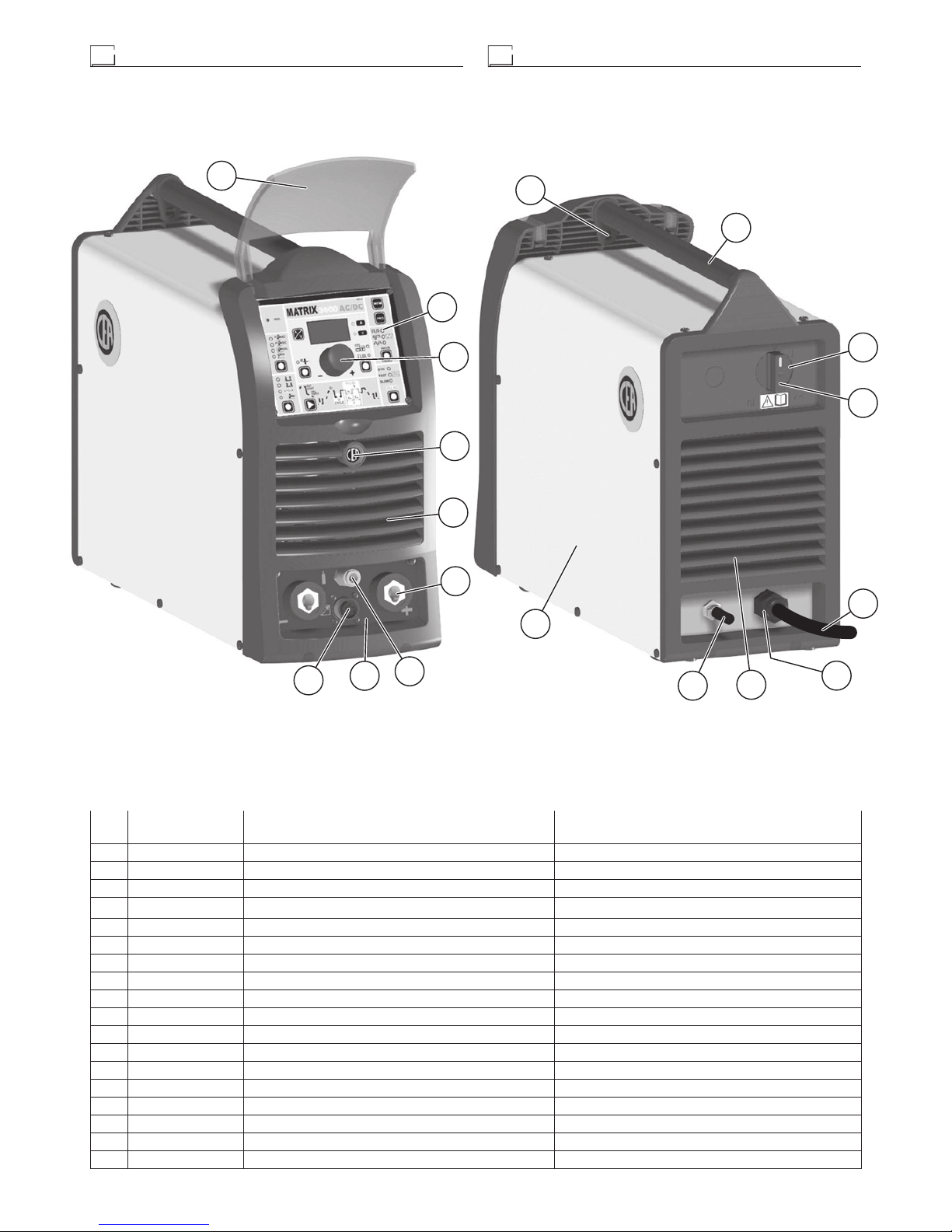
COMMAND AND CONTROL UNITS (Fig. A)
Pos. 1 MTA command and control panel.
Pos. 2 Positive pole quick connection.
Pos. 3 Fast coupling TIG torch gas tube.
Pos. 4 TIG weld auxiliary control connector (torch button, re-
mote controlpedal, etc.).
Pos. 5 Negative pole quick connection.
Pos. 6 Power supply switch. In the “O” position the welder is
off.
Pos. 7 Mains cable.
Pos. 8 Welding gas hose.
Table 2
Model
MATRIX 2200 AC/DC
MATRIX 3000 AC/DC
MATRIX 3000 AC/DC R
TIG MMA TIG MMA
Input power @ I
2
Max kVA 6,5 7,0 9,6
Delayed fuse (I
2
@ 100%) A 16 10
Duty cycle @ X% (40°C) A 220 (30%) 180 (30%) 300 (35%) 250 (40%)
Mains cable
Length
Section
m
mm
2
3,5
2,5
4
2,5
Ground cable
Section mm
2
25 35

5
Interfacing accessories (optional)
“RoboMAT 1” analogue / digital robot interface
Fitted on the back of the MATRIX 3000 AC/DC R welding machine
(Pos. 1, Fig. B).
“RoboMAT 1” analogue / digital robot interface
connection cable - Cutting robot or for automatic
equipment
Connect the cable to the analogue / digital interface as shown in
figure (Pos. 2, Fig. B).
To connect the other end of this cable see the diagram in the manualfor the “RoboMAT 1” analogue / digital robot interface.
IMPORTANT: Do not keep the “RoboMAT 1” analogue / digital robot interface connected to the generator, unless it is also powered
by the automatic system.
1
2
FIG. B
6
7
8
1
2
5
5
3
4
4
1
2
MATRIX 3000 AC/DC - AC/DC R
MATRIX 2200 AC/DC
6
7
8
3
FIG. A

6
TIG welding
In the TIG process welding is achieved by melting the two metal
pieces to be joined, with the possible addition of material from the
outside, using an arc ignited by a tungsten electrode. The molten
bath and the electrode are protected by and inert gas (for example, Argon). This type of welding is used to weld thin sheet metal
or when elevated quality is required.
1) Connecting the welding cables (Fig. C):
• Connect the gas hose to the Argon cylinder.
• With the machine switched off:
-
Connect the ground cable to the snap-on connector
marked + (positive).
-
Connect the relative ground clamp to the workpiece or
to the workpiece support in an area free of rust, paint,
grease, etc..
-
Connect the TIG torch power cable to the snap-on connector marked - (negative).
-
Connect the torch gas tube to the connection (Pos. 3,
Fig. A).
-
Insert the torch button connector in the 6 poles holder
(Pos. 4, Fig. A).
2) Switch the welding machine on by moving the power supply
switch to I (Pos. 6, Fig. A).
3) Make the adjustments and select the parameters on the con-
trol panel (for further information see the MTA control panel
manual).
TIG WELDING WITH “Lift” TYPE STRIKING
4a) Open the gas cylinder and flow regulator.
5a) Put the electrode at the point at which welding is to begin, put
the TIG torch at an angle so that the edge of the gas nozzle
is not on top of the piece to be welded, keeping contact between the point of the electrode and the piece to be welded
(Fig. D-1).
6a) Press the torch button.
7a) The “Lift” function strikes the arc when the TIG torch electrode
comes into contact with the workpiece and is then removed
(Fig. D-2)
8a) Carry out TIG welding (Fig. D-3).
To end welding:
•
Lift the torch slowly, at a certain point the welding current
decreases, and then stop.
•
The welding machine follows an automatic down slope
along with extinguishing of the arc.
9a) When finished welding remember to shut off the gas cylinder.
TIG WELDING WITH HIGH FREQUENCY STRIKING (HF)
4b) Open the gas cylinder and flow regulator.
5b) Put the electrode at the point at which welding is to begin, put
the TIG torch at an angle so that the edge of the gas nozzle is
not on top of the piece to be welded, keeping a 2-3 mm gap
between the point of the electrode and the piece to be weld-
ed (Fig. E-1).
6b) Press the torch button.
7b) The voltaic arc strikes even without contact between the TIG
torch electrode and the workpiece (Fig. E-2).
8b) To continue welding put the torch back in its normal position
(Fig. E-3).
IMPORTANT: The high frequency switches off automatically after switching on.
FIG. F
2000HA73
2000HA72
FIG. D FIG. E
FIG. C

7
PART TO BE WELDED
The part to be welded must always be connected to ground in order to reduce electromagnetic emission. Much attention must be
afforded so that the ground connection of the part to be welded
does not increase the risk of accident to the user or the risk of damage to other electric equipment. When it is necessary to connect
the part to be welded to ground, you should make a direct connection between the part and the ground shaft. In those countries
in which such a connection is not allowed, connect the part to be
welded to ground using suitable capacitors, in compliance with the
national regulations.
WELDING PARAMETERS
Table 3 shows the currents to use with the respective electrodes
for TIG welding. This input is not absolute but is for your guidance
only; read the electrode manufacturers’ instructions for a specific
choice. The diameter of the electrode to use is directly proportional to the current being used for welding.
Table 3
Ø ELECTRODE (mm) CURRENT (A)
1,2
1,6
2,4
3,2
4,0
10 ÷ 80
70 ÷ 150
140 ÷ 250
225 ÷ 400
300 ÷ 500
Electrode welding (MMA)
The welding electrode is used to weld most metals (various types
steel, etc.),for which rutilic and basic electrodes are used.
1) Connecting the welding cables (Fig. F):
Disconnect the machine from the mains power supply and con-
nect the welding cables to the output terminals (Positive and
Negative) of the welding machine, attaching them to the clamp
and ground with the polarity specified for the type of electrode
being used (Fig.F). Always follow the electrode manufacturer’s instructions. The welding cables must be as short as possible, they must be near to one another, positioned at or near
floor level. Do not touch the electrode clamp and the ground
clamp simultaneously.
2) Switch the welding machine on by moving the power supply
switch to I (Pos. 6, Fig. A).
3) Make the adjustments and select the parameters on the control panel (for further information see the MTA control panel
manual).
4) Carry out welding by moving the torch to the workpiece. Strike
the arc (press the electrode quickly against the metal and then
lift it) to melt the electrode, the coating of which forms a protective residue. Then continue welding by moving the electrode
from left to right, inclining it by about 60° compared with the
metal in relation to the direction of welding.
PART TO BE WELDED
The part to be welded must always be connected to ground in order to reduce electromagnetic emission. Much attention must be
afforded so that the ground connection of the part to be welded
does not increase the risk of accident to the user or the risk of damage to other electric equipment. When it is necessary to connect
the part to be welded to ground, you should make a direct connection between the part and the ground shaft. In those countries
in which such a connection is not allowed, connect the part to be
welded to ground using suitable capacitors, in compliance with the
national regulations.
WELDING PARAMETERS
Table 4 shows some general indications for the choice of electrode, based on the thickness of the parts to be welded. The values of current to use are shown in table 5 with the respective
electrodes for the welding of common steels and low-grade al
loys. These data have no absolute value and are indicative data
only. For a precise choice follow the instructions provided by the
electrode manufacturer.
Table 4
WELDING THICKNESS (mm) Ø ELECTRODE (mm)
1,5 ÷ 3
3 ÷ 5
5 ÷ 12
≥ 12
2
2,5
3,2
4
Table 5
Ø ELECTRODE (mm) CURRENT (A)
1,6
2
2,5
3,2
4
5
30 ÷ 60
40 ÷ 75
60 ÷ 110
95 ÷ 140
140 ÷ 190
190 ÷ 240
The current to be used depends on the welding positions and the
type of joint, and it increases according to the thickness and di
mensions of the part.
The current intensity to be used for the different types of welding,
within the field of regulation shown in table 5 is:
• High for plane, frontal plane and vertical upwards welding.
• Medium for overhead welding.
•
Low for vertical downwards welding and for joining small pre-
heated pieces.
A fairly approximate indication of the average current to use in
the welding of electrodes for ordinary steel is given by the following formula:
I = 50 × (Øe - 1)
Where:
I = intensity of the welding current
Øe = electrode diameter
Example:
For electrode diameter 4 mm
I = 50 × (4 - 1) = 50 × 3 = 150A
Maintenance
ATTENTION: Before carrying out any inspection of the inside of
the generator, disconnect the system from the supply.
SPARE PARTS
Original spare parts have been specially designed for our equipment. The use of non-original spare parts may cause variations in
performance or reduce the foreseen level of safety.
We decline all responsibility for the use of non-original spare parts.
GENERATOR
As these systems are completely static, proceed as follow:
•
Periodic removal of accumulated dirt and dust from the inside
of the generator, using compressed air. Do not aim the air jet
directly onto the electrical components, in order to avoid dam-
aging them.
• Make periodical inspections in order to individuate worn cables
or loose connections that are the cause of overheating.

8
Optional
The remote controls can be only used in the 2-STROKE and
4-STROKE welding modes.
MANUAL REMOTE CONTROL
WARNING: When using the machine for TIG welding it is OBLIGA-
TORY to use the kit for simultaneously use – CEA code n° 460056.
Weld current can be measured at a distance by connecting up this
control. The display will show the previous maximum weld current
value set on the welder. The remote control will adjust welding current from the minimum to this value (for further information see the
MTA control panel manual). Just turn the adjustment knob on the
welder to change the maximum output value.
FOOT SWITCH
The foot switch replaces the torch button and the welding current
setting knob. The display will show the previous maximum weld
current value set on the welder. The pedal will adjust the welding
current from the minimum to this value (for further information see
the MTA control panel manual). Just turn the adjustment knob on
the welder to change the maximum output value.
NOTE:
•
To use the pedal control correctly, set the “welding mode” to
2-STROKE and then the welding parameters SLOPE UP time
to 0 sec., SLOPE DOWN time to 0 sec.
• When using the machine for TIG welding the operator can use
the torch button to start the weld and the pedal to regulate the
welding current remotely..
AIR AND/OR WATER-COOLED TORCH UP/ DOWN
The up/down torch replaces the current setting knob on the front
of the welder. Press right (+) and left (-) button to adjust the active parameter. With this kind of torch, it is also possible to scroll
the saved programmes by pressing the two (+) and (-) buttons.
Turn the knob to scroll the programmes until an empty and unused
programme is found.
NOTE: Programme sequences can be created by placing an empty programme between saved ones.
NOTE: The value shown on the display during welding represents
the effective current output with all types of control.
The digital control unit of the generator is fitted with a control recognition device which allows it to identify which device is connected and take action accordingly. To allow the command recognition
device to work correctly, connect (with the machine switched off)
the required accessory to the relative connector and then switch
on the welding machine with the on/off switch.
NOTE: It is not possible to memorize or open programmes
when the remote controls are connected (except for the torch
with UP/DOWN commands).
If a remote control is connected (followed by self-acknowledgement procedure) the machine will automatically return to the manual-welding phase if it has been pre-set for automatic welding.
The pointing out of any difficulties
and their elimination
The supply line is attributed with the cause of the most common
difficulties. In the case of breakdown, proceed as follows:
1) Check the value of the supply voltage
2) Check that the power cable is perfectly connected to the plug
and the supply switch
3) Check that the power fuses are not burned out or loose
4) Check whether the following are defective:
• The switch that supplies the machine.
• The plug socket in the wall.
• The generator switch.
NOTE: Given the required technical skills necessary for the repair
of the generator, in case of breakdown we advise you to contact
skilled personnel or our technical service department.
Digital interface PCB replacement
• Unscrew the 4 screws fastening the front rack panel.
• Remove the adjustment knob.
• Extract wiring connectors from digital interface PCB.
• Unscrew small supporting columns.
• Remove digital interface PCB by lifting it out of its supports.
• Proceed vice versa to assemble new digital interface PCB.

9
Meaning of graphic symbols on machine
Adjustment of electronic circuit board
PT1 Adjustment of the maximum current
PT2 Adjustment of the minimum current
Power supply switch
System for use in environments with increased risk
of electroshock
Product suitable for free circulation in the European
Community
Danger! High voltage
Grounding
Positive pole snap-in connector
Negative pole snap-in connector
Connector for the remote control
Warning!
Fast coupling TIG torch gas tube
Before using the equipment you should carefully
read the instructions included in this manual
MMA welding
TIG welding
Special disposal
PT1
PT2

10
Wiring diagram (MATRIX 2200 AC/DC)

11
2101WA31

12
Wiring diagram (MATRIX 3000 AC/DC - AC/DC R)
3000
MTA 30

13
2101WB09

14
Key to the electrical diagram
•1 Capacitor •2 Power supply connector 230V 50/60Hz •3 EMC capacitors
•4 Power supply connector for the cooling system •5 TIG torch connec-
tor •6 Secondary diode •7 “Dual Boost Chopper” IGBT •8 Digital display •9
Secondary diode discharger •10 Encoder •11 Gas solenoid valve •12 Fuse
•13 Torch filter complete with connector •14 EMC filter •15 HF filter •16 Wa-
ter cooling system •17 Power supply switch •18 Inductor •19 PFC inductances •20 Electric pump •21 Primary IGBT circuit •22 “Full Bridge” IGBT
•23 Secondary IGBT circuit •24 Fan motor •25 Secondary R-C diode •26
Membrane keyboard •27 Primary rectifier •28 Secondary IGBT protection
board resistance •29 Interface for automation (optional extra) •30 Digital
interface PCB •31 Inverter PCB •32 Automation interface isolation board
(optional extra) •33 Secondary circuit diodes PCB •34 Secondary circuit
PCB •35 EMC filter PCB •36 High frequency (HF) PCB •37 Secondary circuit IGBT board •38 Secondary IGBT protection board •39 Current transducer •40 Toroidal ferrite •41 Secondary circuit diode thermostat •42 HF
transformer •43 Primary circuit thermistor •44 Secondary circuit thermostat •45 Transformer •46 Pressure switch
Colour key
AN Orange-Black
Ar Orange
Az Sky blue
Bc White
Bl Blue
BN White-Black
Gg Grey
Gl Yellow
GV Yellow-Green
Mr Brown
Nr Black
Ro Pink
Rs Red
Vd Green
Vl Violet
•1 •2 •3 •4 •5 •6 •7 •8 •9 •10
C CA CP CR CT D DB DD DS ED
•11 •12 •13 •14 •15 •16 •17 •18 •19 •20
EVG F FCTA FE FHF HR IL L L1-2 M
•21 •22 •23 •24 •25 •26 •27 •28 •29 •30
MI MI2 MIS MV RC RF RP RSP S-AI S-INT DIG
•31 •32 •33 •34 •35 •36 •37 •38 •39 •40
S-INV S-ISR SD SDRV SF SHF SI SP TC TF
•41 •42 •43 •44 •45 •46
TH THF THP THS TP W

IT
Lista ricambi
LEGGERE ATTENTAMENTE
EN
Spare parts list
READ CAREFULLY
MATRIX AC/DC • AC/DC R
2200 • 3000
CEA COSTRUZIONI ELETTROMECCANICHE ANNETTONI S.p.A.
C.so E. Filiberto, 27 - 23900 Lecco - Italy
Tel. ++39.0341.22322 - Fax ++39.0341.422646
Cas. Post. (P.O.BOX) 205
E-mail: cea@ceaweld.com - web: www.ceaweld.com

2
Pos.
MATRIX 2200
AC/DC
Descrizione Description
1 352453 Visiera rack frontale Front rack transparent visor
2 447846 Tastiera a membrana MATRIX 2200 AC/DC MATRIX 2200 AC/DC Membrane keyboard
3 438888 Manopola senza indice Ø29mm Ø29mm Knob without index
4 468191 Adesivo logo CEA Ø20mm CEA logo sticker Ø20mm
5 352452 Pannello frontale senza adesivo logo CEA Ø20mm Front panel without CEA logo sticker Ø20mm
6 403611 Attacco rapido Quick connection
7 403635 Attacco rapido gas Gas quick connection
8 468282 Adesivo dinse Dinse sticker
9 419050 Connettore comando a distanza Remote control socket
10 462694 Gancio attacco tracolla Carrying belt hook
11 438108 Maniglia Handle
12 438710 Manopola interruttore alimentazione Mains switch knob
13 435375 Interruttore alimentazione Mains switch
14 235942 Cavo alimentazione Mains cable
15 427895 Pressacavo completo di ghiera Cable clamp with lock ring
16 352404 Pannello posteriore Rear panel
17 485040 Tubo gas Gas tube
18 420493 Coperchio con adesivi logo CEA Cover with CEA logo stickers
IT
Lista ricambi (MATRIX 2200 AC/DC)
EN
Spare parts list (MATRIX 2200 AC/DC)
1
2
3
4
5
6
7
9
8
10
11
12
13
14
16
18
17
15

3
Pos.
MATRIX 2200
AC/DC
Descrizione Description
19 377094 Scheda filtro EMC EMC filter PCB
20 413538 Cablaggio scheda filtro EMC EMC filter PCB wiring
21 413536 Cablaggio ausiliario Auxiliary wiring
22 286036 IGBT "Dual Boost Chopper" "Dual Boost Chopper" IGBT
23 286038 IGBT "Full Bridge" "Full Bridge" IGBT
24 376930 Filtro torcia completo di connettore Torch filter with connector
25 403782 Terminale per connettore femmina 3x2 vie Terminal for 3x2 poles female connector
26 419074 Connettore femmina 3x2 vie 3x2 Poles female connector
27 352466 Scatola scheda HF HF PCB box
28 377059 Scheda alta frequenza (HF) High frequency (HF) PCB
29 352468 Coperchio scatola scheda HF HF PCB cover
30 377097 Scheda diodi circuito secondario Secondary circuit diode PCB
31 478786 Termostato diodi circuito secondario Secondary circuit diode thermostat
32 423236 Diodo secondario Secondary diode
33 455509 Raddrizzatore primario Primary rectifier
34 240473 Complessivo scheda inverter primario Primary inverter PCB assembly
19
20
21
22
23
24
25
26
27
28
29
30
31
32
33
34

4
Pos.
MATRIX 2200
AC/DC
Descrizione Description
35 431331 Piedino d'appoggio Foot
36 404933 Basamento Base
37 352944 Isolamento dinse Dinse Insulation
38 449495 Telaio metallico interno Internal metallic frame
39 463217 Staffa fissaggio trasformatore Transformer support
40 481402 Trasformatore Transformer
41 240234 Induttore Inductor
42 240232 Induttanze PFC PFC inductors
43 239995 Trasformatore HF HF transformer
44 427681 Filtro HF HF filter
45 481946 Trasduttore di corrente Current transducer
46 486383 Motore ventilatore Fan motor
47 425933 Elettrovalvola gas Gas solenoide valve
48 286041 IGBT secondario Secondary IGBT
49 240510 Complessivo IGBT secondario Secondary IGBT assembly
50 377095 Scheda interfaccia digitale Digital Interface PCB
51 454150 Encoder Encoder
35
36
37
38
39
40
41
42
43
44
45
46
47
48
49
51
50
5
Pos.
MATRIX 3000
AC/DC - AC/DC R
Descrizione Description
1 352453 Visiera rack frontale Front rack transparent visor
2 447859 Tastiera a membrana MATRIX 3000 AC/DC Membrane Keyboard MATRIX 3000 AC/DC
3 438888 Manopola senza indice Ø29mm Ø29mm Knob without index
4 468191 Adesivo logo CEA Ø20mm CEA logo sticker Ø20mm
5 352452 Pannello frontale senza adesivo logo CEA Ø20mm Front panel without CEA logo sticker Ø20mm
6 403611 Attacco rapido Quick connection
7 403635 Attacco rapido gas Gas quick connection
8 468282 Adesivo frontale Front sticker
9 419050 Connettore comando a distanza Remote control socket
10 462694 Gancio attacco tracolla Carrying belt hook
11 438104 Maniglia Handle
12 438710 Manopola interruttore alimentazione Mains switch knob
13 435755 Interruttore alimentazione Mains switch
14 235994 Cavo alimentazione Mains cable
15 427895 Pressacavo completo di ghiera Cable clamp with lock ring
16 352404 Pannello posteriore Rear panel
17 485040 Tubo gas Gas tube
18 420487 Coperchio con adesivi logo CEA Cover with CEA logo stickers
IT
Lista ricambi (MATRIX 3000 AC/DC - AC/DC R)
EN
Spare parts list (MATRIX 3000 AC/DC - AC/DC R)
1
2
3
4
5
6
7
9
8
10
11
12
13
14
16
18
17
15

6
Pos.
MATRIX 3000
AC/DC - AC/DC R
Descrizione Description
19 413466 Cablaggio ausiliario Auxiliary wiring
20 413518
Cablaggio RoboMat 1 - Matrix 3000 AC / DC R
(solo per MATRIX 3000 AC/DC R)
RoboMat 1 - Matrix 3000 AC / DC R Wiring
(only for MATRIX 3000 AC/DC R)
21 478867 Termistore circuito primario Primary circuit thermistor
22 353052 Isolamento scheda inverter Inverter PCB insulation
23 239989 Trasformatore HF HF transformer
24 376930 Filtro torcia completo di connettore Torch filter with connector
25 427681 Filtro HF HF filter
26 352466 Scatola scheda HF HF PCB box
27 377059 Scheda alta frequenza (HF) High frequency (HF) PCB
28 352468 Coperchio scatola scheda HF HF PCB cover
29 457122 Resistore scheda protezione IGBT secondario Secondary IGBT protection PCB resistor
30 376887 Filtro EMC EMC Filter
31 486383 Motore ventilatore Fan motor
32 286046 IGBT circuito primario Primary circuit IGBT
33 455508 Raddrizzatore primario Primary rectifier
34 240459 Complessivo scheda inverter primario Primary inverter PCB assembly
19
20
21
22
23
24
25
26
27
28
29
30
31
32
33
34

7
Pos.
MATRIX 3000
AC/DC - AC/DC R
Descrizione Description
35 431329 Piedino d'appoggio Foot
36 418858 Assieme condensatori Capacitors assembly
37 352944 Isolamento dinse Dinse Insulation
38 449485 Telaio metallico interno Internal metallic frame
39 463218 Staffa fissaggio trasformatore Transformer support
40 481436 Trasformatore Transformer
41 481946 Trasduttore di corrente Current transducer
42 419074 Connettore femmina 3x2 vie 3x2 Poles female connector
43 377144 Scheda snubber / diodi circuito secondario Secondary circuit diode / snubber PCB
44 423236 Diodo secondario Secondary diode
45 478846 Termostato circuito secondario Secondary circuit thermostat
46 377143 Scheda circuito secondario Secondary circuit PCB
47 286047 IGBT secondario Secondary IGBT
48 377154 Scheda protezione IGBT secondario Secondary IGBT protection PCB
49 425938 Elettrovalvola gas Gas solenoide valve
50 404912 Basamento Base
51 377152A Scheda interfaccia digitale Digital Interface PCB
52 454150 Encoder Encoder
53 377170
Scheda isolamento interfaccia per automazione
(solo per MATRIX 3000 AC/DC R)
Robotic interface isulation PCB
(only for MATRIX 3000 AC/DC R)
35
36
38
37
39
40
41
42
43
44
45
46
47
48
49
50
53
51
52

8
IT
Ordinazione dei pezzi di ricambio
Per la richiesta di pezzi di ricambio indicare chiaramente:
1) Il numero di codice del particolare
2) Il tipo di impianto
3) La tensione e la frequenza che rileverete dalla targhetta
dei dati posta sull’impianto
4) Il numero di matricola
ESEMPIO
N° 2 pezzi, codice n. 352453 - per l’impianto MATRIX 3000 AC/
DC - 400 V - 50/60 Hz - Matricola n° ........................................
EN
Ordering spare parts
To ask for spare parts clearly state:
1) The code number of the piece
2) The type of device
3) The voltage and frequency read on the rating plate
4) The serial number of the same
EXAMPLE
N. 2 pieces code n. 352453 - for MATRIX 3000 AC/DC - 400 V
- 50/60 Hz - Serial number .......................................................

MTA 22 - 30
EN
Operator’s manual
READ CAREFULLY
CEA COSTRUZIONI ELETTROMECCANICHE ANNETTONI S.p.A.
C.so E. Filiberto, 27 - 23900 Lecco - Italy
Tel. ++39.0341.22322 - Fax ++39.0341.422646
Cas. Post. (P.O.BOX) 205
E-mail: cea@ceaweld.com - web: www.ceaweld.com
2
ENGLISH
EN
Control panel 2
Introduction 2
Displaying the software version installed 5
Electrode welding (MMA) 5
TIG “AC” welding 5
TIG “DC” welding 8
TIG “AC and LIFT DC” welding with the SPOT
WELDING function on 8
TIG HF DC welding with TACK function active and
single ColdTack point 9
TIG HF DC welding with TACK function active and
Multi-ColdTack function 9
TIG “AC and DC” welding - Welding parameters 10
STANDARD CONFIGURATION (Std) 10
1 - “BASIC” WELDING PARAMETERS 10
2 - WELDING PARAMETERS with PULSE
mode active 10
3 - WELDING PARAMETERS with PULSE
mode and CYCLE welding mode active
(CYCLE LED on) 12
SPECIAL CONFIGURATION (SPE) 13
Introduction
This manual describes the functions on and how to use the following control panels:
• MTA 22
• MTA 30
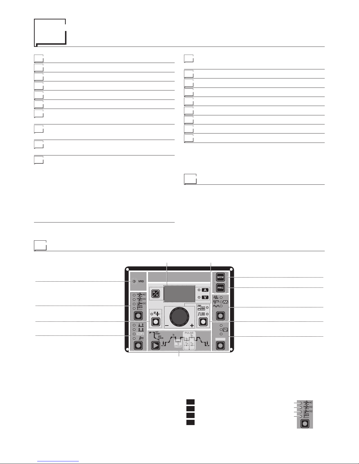
Control panel
■ VRD
The Voltage Reduction Device (VRD) is a safety device that reduces the voltage. It prevents voltages forming on the output terminals that may pose a danger to people.
Two-tone LED (off - red - green) indicates enabling of the VRD
device.
The standard, preset settings for the firm do not activate the VRD
function on the welding machine and so this LED is normally off.
To activate the VRD device, see the relevant paragraph.
■ WELDING PROCESS
The MATRIX welding machine offers 4 TIG/Electrode welding
processes. Each time the button is pushed, the welding machine
switches to select the welding process indicated by the LED that
stays lit, in the following order:
L1 TIG AC with HF ignition
L2 TIG DC with HF ignition
L3 TIG DC with “Lift” type ignition
L4 ELECTRODE (MMA)
L1
L2
L3
L4
PULSE
SYN
FAST
SLOW
WAVE
WELDING PARAMETERS
ENCODER knobDISPLAY
VRD
WELDING PROCESS
ELECTRODE DIAMETER
WELDING MODE
SAVE “MEM”
PROGRAM “PRG”
WAVE
BALANCING and FREQUENCY
PULSE
2000HC05
Editing the maximum and minimum limits for
welding parameters 14
Creating and memorising automatic welding points 15
PROGRAMMED and/or MANUAL welding 15
Calling up saved programs 15
Viewing the parameters set 16
Activating the VRD device 16
Auxiliary functions 16
Factory default 16
Error and protection conditions 16
3
■ ELECTRODE DIAMETER
For TIG welding with HF ignition, it allows you to use the
relevant key to set the diameter of the tungsten electrode
used, and/or to change it using the ENCODER knob, in
order to achieve the best control of the AC arc in a synergic manner.
WARNING: The electrode diameter CANNOT be selected when
the welding machine is set for the SPECIAL configuration.
■ WELDING MODE
The MATRIX welding machine offers 4 welding modes. Each time
the button is pushed, the welding machine switches to select the
welding mode indicated by the LED that stays lit, in the following order:
L5 2 STROKES
L6 4 STROKES
L7 CYCLE
L8 SPOT WELDING
L5
L6
L7
L8
L5 2 STROKES
When the torch button is pushed welding begins starting with the
INITIAL CURRENT (if SLOPE UP is selected), while when it is released welding ends when the FINAL CURRENT is reached (if
SLOPE DOWN is set).
L6 4 STROKES
TIG welding takes place as follows:
• When the torch button is pushed welding begins at the INITIAL
current.
•
When the torch button is released the SLOPE UP process is
carried out (if applicable) and the current returns to the PRINCIPAL value I1 .
•
When the torch button is pushed the SLOPE DOWN process
is carried out (if applicable) and the current returns to the FINAL value.
• When the button is released the welding cycle ends.
L7 CYCLE
When this function has been activated, TIG welding takes place
as follows:
• When the torch button is pushed welding begins at the INITIAL
current.
•
When the torch button is released the SLOPE UP process is
carried out (if applicable) and the current returns to the PRINCIPAL value I1 .
• When the torch button is pressed and released within less than
1 second the welding current goes to the CYCLE value ( I2 ), and
by repeating this operating you can move between the two current levels ( I
1 ), ( I2 ) an infinite number of times.
•
When the torch button is pushed and held down (for longer than
1 second) you exit the cycle, the SLOPE DOWN process is carried out (if applicable) and the current returns to the FINAL val-
ue. When the torch button is released the welding cycle ends.
This welding mode is especially indicated for welding profiles with
different thickness, where continuous current variation is required.
Also, when welding aluminium, it allows you to have a higher initial
current, thereby facilitating pre-heating of the workpiece.
L8 SPOT WELDING
This can be used by pushing the torch button to spot weld for a preset period of time (in seconds) at the end of which the arc switches
off automatically. The tack welding function is divided into 3 types:
• TIG AC and TIG LIFT DC tack welding.
• TIG HF DC tack welding with a single coldTack point.
• TIG HF DC tack welding with a Multi-ColdTack function.
See the relevant paragraphs in the subsequent pages of this manual.
■ DISPLAY
Displays the selections made using the various Keys (with corresponding LED on or flashing) and regulated using the ENCODER knob.
The
button can also be used to view:
L32 AMPERE (CURRENT )
•
When the machine is in stand-by, the Amps (A) set.
• When the machine is welding the real Amps (A) at
which the operator is actually welding.
WARNING: LED L32 switched on and steady.
L33 VOLT (VOLTAGE)
•
The actual VOLTS (V) at the welding clamps (the
value displayed CANNOT BE CHANGED OR
REGULATED).
WARNING: LED L33 switched on and steady.
■ ENCODER knob
This is used to regulate and change the welding parameters, according to which LED is switched on
and the value shown on the DISPLAY, which is necessary for the machine to work correctly.
■ SAVE “MEM”
Used to save the parameters for the welding programs.
■ PROGRAM “PRG”
Used to call up welding programs.
■ WAVE
During TIG AC welding with HF ignition, it makes it possible to control the following wave shapes:
L24 DYNAMIC TIG
L25 SPEED TIG
L25 COLD TIG
L26 SOFT TIG
WAVE
L24
L25
L26
L24 DYNAMIC TIG
Square wave: highly dynamic arc for all applications.
WARNING: LED L24 switched on and steady.
L25 SPEED TIG
Mixed wave: excellent penetration with high welding speed and
low electrode consumption.
WARNING: LED L25 switched on and steady.
L25 COLD TIG
Triangular wave: low heat generation with reduced distortion, ideal for minor thicknesses.
WARNING: LED L25 switched on and flashing.
L26 SOFT TIG
Sinusoidal wave: gentle, soft arc with low noise, ideal for average thicknesses.
WARNING: LED L26 switched on and steady.
■ BALANCING and FREQUENCY
During TIG AC welding with HF ignition, it makes it possible to set
one of the following parameters, using the relevant key:
L30 BALANCING of the TIME and
AMPLITUDE of the AC welding
current (BALANCE PLUS)
L31 FREQUENCY of the AC welding
current
L30
L31
L30 BALANCING of the TIME and AMPLITUDE of the AC
welding current (BALANCE PLUS)
It is possible to adjust both the time (t) and the amplitude of the
current (I) independently or simultaneously, using positive or negative values for the time the electrode stays in place. These settings ensure perfect control of penetration and cleanliness, with a
drastic reduction in side incisions.
L31 FREQUENCY of the AC welding current
The high frequency makes it possible to weld minor thicknesses
with excellent results, while the low frequency is ideal for welding
average thicknesses, or where edge preparation is poor.
WARNING: LED L31 switched on and flashing.

4
■ PULSE
When using one of the 3 TIG welding processes, it makes it possible to set one of the 4 pulsation modes available on the welding
machine, using the relevant button:
L27 SYN PULSE
L28 FAST PULSE
L28 ULTRA FAST PULSE
L29 SLOW PULSE
PULSE
SYN
FAST
SLOW
L27
L28
L29
L27 Synergic pulsations (SYN PULSE)
WARNING:
LED L27 switched on and steady.
This can only be programmed when the TIG DC with HF ignition
or TIG DC with “Lift” type ignition welding processes are used.
L28 Fast pulsations (FAST PULSE)
WARNING:
LED L28 switched on and steady.
This can only be programmed when the TIG DC with HF ignition
or TIG DC with “Lift” type ignition welding processes are used.
L28 Ultra fast pulsations (ULTRA FAST PULSE)
WARNING:
LED L28 switched on and flashing.
Attivabile solo con i processi di saldatura TIG DC con innesco HF
o TIG DC con innesco tipo “Lift”.
L29 Slow pulsations (SLOW PULSE)
WARNING:
LED L29 switched on and steady.
This can only be programmed when the 3 TIG welding process-
es are used.
WARNING: The operator can decide to TIG weld without using
any pulsation mode. If this is the case, the 4 LEDs are switched off.
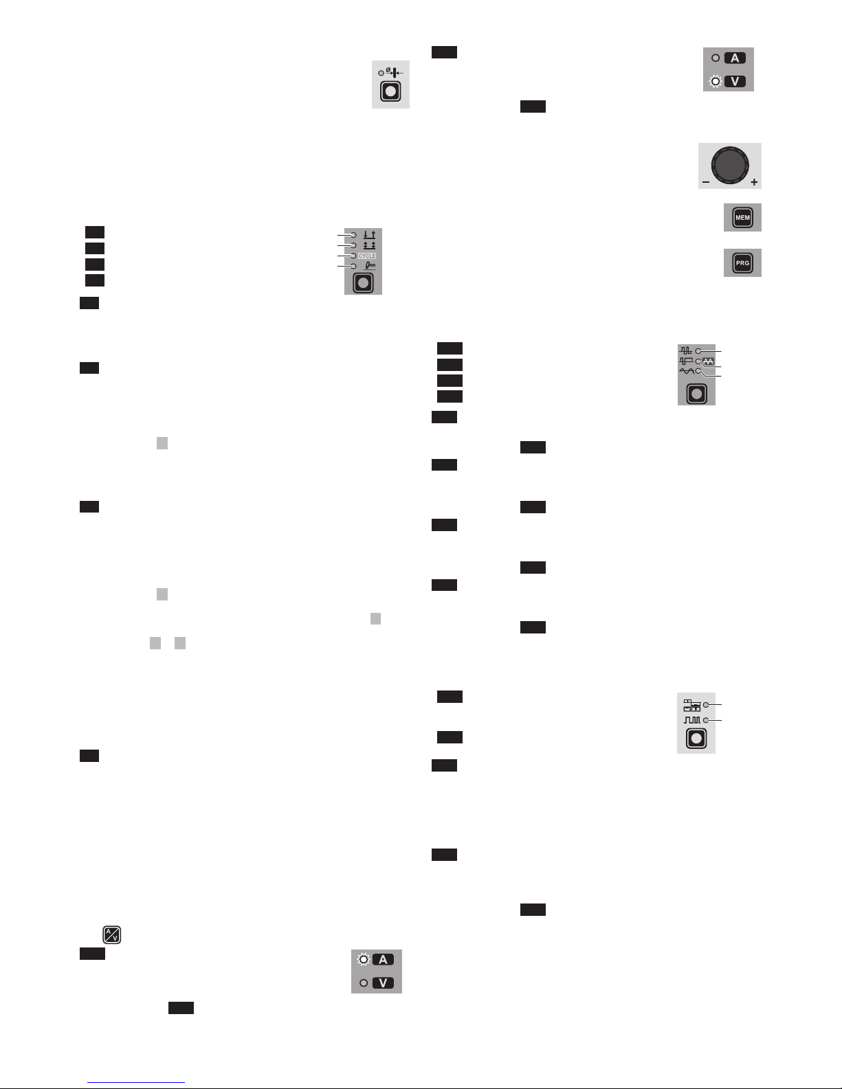
■ WELDING PARAMETERS
Each time the button is pushed, the welding machine selects the
next function according to the machine configuration, the welding
process, the welding mode, etc...
1A - STANDARD CONFIGURATION
Electrode welding (MMA)
When using the electrode welding process, this allows you to select
the following welding parameters, based on which LED is flashing:
L9 HOT START
L10 ARC FORCE
L11 PRINCIPAL welding CURRENT I
1
L9 L10 L 11
1B - STANDARD CONFIGURATION
TIG welding
When one of the 3 TIG welding processes available on the welding
machine is activated, this allows you to select the following welding parameters, based on which LED is flashing:
L12 PRE-GAS duration
L13 SLOPE UP duration
L14 BASE current duration T
b
WARNING: This can only be programmed when SLOW pulsa-
tion is activated.
L15 PEAK current duration Tp
WARNING: This can only be programmed when SLOW pulsa-
tion is activated.
L16 SLOPE DOWN duration
L17 POST-GAS duration
L18 INITIAL welding CURRENT
L11 PRINCIPAL welding CURRENT I
1
L19 CYCLE CURRENT I2
WARNING: This can only be programmed when the CYCLE weld-
ing mode is active.
L20 BASE CURRENT Ib
WARNING: This can only be programmed when at lease one pul-
sation mode is activated.
L21 PEAK CURRENT Ip
WARNING: This can only be programmed when at least one pul-
sation mode is activated.
L22 FINAL welding CURRENT
L23 PULSATION FREQUENCY f
WARNING: NOT programmable when SLOW pulsation mode is
active.
L18 L11 L19 L20 L21 L22
L17L16L15L23L14L13L12
2 - SPECIAL CONFIGURATION
(only for expert welders)
TIG welding
For this configuration, in addition to the parameters already defined for the STANDARD configuration, you can also set the following parameters:
L9 IGNITION CURRENT
WARNING: This can only be programmed when the TIG AC with
HF ignition or TIG DC with HF ignition welding processes are
used.
L9 IGNITION TIME duration
WARNING: Only programmable when the TIG AC with HF igni-
tion welding process is activated.
L18 INITIAL welding CURRENT
WARNING: This can only be programmed when the TIG AC with
HF ignition or TIG DC with HF ignition welding processes and
the 2 STROKES welding mode are used.
L22 FINAL welding CURRENT
WARNING: This can only be programmed when the TIG AC with
HF ignition or TIG DC with HF ignition welding processes and
the 2 STROKES welding mode are used.
L9 L18 L22
WARNING: This special parameter is only to be activated by
qualified personnel, or those trained by technicians.

5
Displaying the software
version installed
The MATRIX AC/DC are fitted with a digital control with software
on board defined in the factory. This software is subject to continuous evolution and improvement. The software is identified by a
specific number that can be viewed on the DISPLAY (D) as follows:
1) When the welding machine is off, push and hold the “MEM”
SAVE key down (T1).
2) Start the welding machine by turning the power supply switch
to position I.
3) For a few seconds the DISPLAY (D) shows the type of soft-
ware on board (e.g. b01) where:
• b indicates the welding machine model.
• 01 indicates the VERSION of the software installed
I2
HOT
START
ARC
FORCE
PULSE
CYCLE
T
b
f
T
p
I1
Ip
Ib
PULSE
SYN
FAST
SLOW
WAVE
VRD
CYCLE
Ø
PULSE
SYN
FAST
SLOW
WAVE
T1
D
Electrode welding (MMA)
1) Start the welding machine by turning the power supply switch
to position I.
2) WELDING PROCESS SELECTION
Push the WELDING PROCESS SELECTION key (T7) to se-
lect the ELECTRODE welding processes for welding with
“HOT START” or “ARC FORCE” devices that can be pro
-
grammed by the user.
3) Turn the ENCODER Knob (E) until the DISPLAY shows the
CURRENT VALUE at which you wish to weld, in relation to
the diameter of the electrode you are using.
I2
HOT
START
ARC
FORCE
PULSE
CYCLE
T
b
f
T
p
I
1
I
p
I
b
PULSE
SYN
FAST
SLOW
WAVE
VRD
CYCLE
Ø
PULSE
SYN
FAST
SLOW
WAVE
E
T7
T10
D
4) WELDING PARAMETERS SELECTION
To refine the weld quality, the following parameters can be set
by pushing the WELDING PARAMETERS SELECTION key
(T10) in succession:
•
HOT START - This increases the welding current, in percentage terms, for a time interval that can be set at the start
of the welding process, thereby reducing the risk of poor fusion at the start of the joint ( L9 - HOT START - 00-100).
•
MMA ARC FORCE - Regulates, in percentage terms, the
dynamic characteristics of the arc ( L10 - ARC FORCE 00-100).
• PRINCIPAL welding CURRENT I1 ( L11 ):
2200 AC/DC 3000 AC/DC
10 ÷ 180 A 10 ÷ 250 A
L9 L10 L 11
The value for the welding parameters can be regulated using
the ENCODER Knob (E).
I2
HOT
START
ARC
FORCE
PULSE
CYCLE
T
b
f
T
p
I1
Ip
Ib
PULSE
SYN
FAST
SLOW
WAVE
VRD
CYCLE
Ø
PULSE
SYN
FAST
SLOW
WAVE
E
D
T10
5) To exit these functions hold the WELDING PARAMETERS
SELECTION key (T10) down for about 1 second, after which
the DISPLAY INDICATION LED switches on and the welding
machine is once again ready to weld at the current indicated
on the DISPLAY (D).
6) Once the all the selections/regulations indicated above have
been made, welding can begin.
7) During the welding process the DISPLAY (D) shows the real
Amps (A) at which the operator is actually welding.
TIG “AC” welding
1) Start the welding machine by turning the power supply switch
to position I.
2) Push the WELDING PROCESS SELECTION key (T7) to select the TIG “HF AC” welding processes for TIG welding in
alternating current with high frequency (HF) ignition.
3) ELECTRODE DIAMETER SELECTION
Select the diameter of the electrode to achieve the best control
of ignition in a synergic manner. Selection is done by pushing
the ELECTRODE DIAMETER Key (T8) (ELECTRODE DIAMETER LED flashing) and using the ENCODER Knob (E) to
regulate the value indicated on the DISPLAY (D).
I2
HOT
START
ARC
FORCE
PULSE
CYCLE
T
b
f
T
p
I1
Ip
Ib
PULSE
SYN
FAST
SLOW
WAVE
VRD
CYCLE
Ø
PULSE
SYN
FAST
SLOW
WAVE
T7
T8
E
D
To confirm the diameter selected, simply push the ELEC-
TRODE DIAMETER Key (T8) again (ELECTRODE DIAMETER LED off).

6
4) SELECTING THE WAVE SHAPE
By pushing the WAVE (T3) button the operator can choose
the best wave shape for their welding needs, from the 4 wave
shapes included:
L24 DYNAMIC TIG
L25 SPEED TIG
L25 COLD TIG
L26 SOFT TIG
WAVE
L24
L25
L26
T3
L24 DYNAMIC TIG
Square wave: highly dynamic arc for all applications.
WARNING:
LED L24 switched on and steady.
The display shows the peak current for pre-setting and
welding.
2200 AC/DC 3000 AC/DC
TIG AC
DYNAMIC TIG 5 ÷ 220 A 5 ÷ 300 A
I (A)
t (s)
L25 SPEED TIG
Mixed wave: excellent penetration with high welding speed
and low electrode consumption. Ideal for average / thick thicknesses and vertical welds. Increases penetration, thermal con
-
trol of the arc, and lifespan of the electrode.
WARNING:
LED L25 switched on and steady.
The display shows the peak current for pre-setting and
welding.
2200 AC/DC 3000 AC/DC
TIG AC
SPEED TIG 5 ÷ 220 A 5 ÷ 300 A
I (A)
t (s)
L25 COLD TIG
Triangular wave: low heat generation with reduced distortion,
ideal for minor thicknesses.
WARNING:
LED L25 switched on and flashing.
The display shows the “RMS” current value for pre-setting and welding.
2200 AC/DC 3000 AC/DC
TIG AC
COLD TIG 16 ÷ 127 A 5 ÷ 173 A
I (A)
t (s)
L26 SOFT TIG
Sinusoidal wave: ensures a gentle, soft arc with limited noise,
ideal for average thicknesses and butt welding.
WARNING:
LED L26 switched on and steady.
The display shows the “RMS” current value for pre-setting and welding.
2200 AC/DC 3000 AC/DC
TIG AC
SOFT TIG 16 ÷ 156 A 5 ÷ 212 A
I (A)
t (s)
5A) BALANCING of the TIME (t) (-35÷+10)
It allows you to adjust the time (t) the positive or negative elec-
trode stays in place independently, guaranteeing perfect control of penetration and cleanliness, drastically reducing side
incisions.
Display - +
-35 85% 15%
I (A)
t (s)
Display - +
0 50% 50%
I (A)
t (s)
Display - +
+10 40% 60%
I (A)
t (s)
Push the BALANCING and FREQUENCY key (T4) once and
use the ENCODER Knob (E) to regulate the value indicated
on the DISPLAY (D).
I2
HOT
START
ARC
FORCE
PULSE
CYCLE
T
b
f
T
p
I1
Ip
Ib
PULSE
SYN
FAST
SLOW
WAVE
VRD
CYCLE
Ø
PULSE
SYN
FAST
SLOW
WAVE
T4
E
D
LED L30 switched on and flashing.
To exit, simply push the BALANCING and FREQUENCY (T4)
key again (BALANCING LED off).

7
5B) BALANCING the AMPLITUDE of the CURRENT (I) (-50÷+20)
It is possible to adjust the amplitude of the current (I) while the
electrode stays in place independently, using positive or negative values, guaranteeing perfect control of penetration and
cleanliness, drastically reducing side incisions.
Display - +
-50 150% 50%
I (A)
t (s)
Display - +
0 100% 100%
I (A)
t (s)
Display - +
+20 80% 120%
I (A)
t (s)
Press the BALANCING and FREQUENCY (T4) key once, wait
a few seconds, and hold the same key down for at least 2 seconds. Then use the ENCODER Knob (E) to adjust the value
shown on the DISPLAY (D).
I2
HOT
START
ARC
FORCE
PULSE
CYCLE
T
b
f
T
p
I1
Ip
Ib
PULSE
SYN
FAST
SLOW
WAVE
VRD
CYCLE
Ø
PULSE
SYN
FAST
SLOW
WAVE
T4
E
D
LED L30 flashing intermittently.
To exit, simply push the BALANCING and FREQUENCY (T4)
key again (BALANCING LED off).
5C) BALANCING (BALANCE PLUS)
It is possible to adjust the time (t) and amplitude of the cur-
rent (I) while the electrode stays in place simultaneously and
independently, using positive or negative values, guaranteeing perfect control of penetration and cleanliness, drastically
reducing side incisions.
For simultaneous setting of the parameters, following the in-
structions given in points 5A and 5B in succession, with the
help (if necessary) of the example shown below.
Display - +
t -15 65% 35%
I -20 120% 80%
I (A)
t (s)
6) FREQUENCY CONTROL IN AC (40 ÷ 250 Hz)
This controls the frequency for the various wave shapes, for
better directional control, reducing the thermally altered area,
with greater penetration and lower electrode consumption.
The high frequency makes it possible to weld very small thicknesses with excellent results, while the low frequency is ideal
for welding average thicknesses, or where edge preparation
is poor.
I (A)
t (s)
I (A)
MIN 40 Hz
MAX 250 Hz
t (s)
To regulate the FREQUENCY push the BALANCING and
FREQUENCY key (T4) twice (FREQUENCY LED flashing)
and use the ENCODER Knob (E) to regulate the value indicated on the DISPLAY (D).
I2
HOT
START
ARC
FORCE
PULSE
CYCLE
T
b
f
T
p
I1
Ip
Ib
PULSE
SYN
FAST
SLOW
WAVE
VRD
CYCLE
Ø
PULSE
SYN
FAST
SLOW
WAVE
T4
E
D
To exit, simply push the BALANCING and FREQUENCY (T4)
key again (FREQUENCY LED off).
7) Press the WELDING MODE SELECTION Key (T9) and go to
one of the 4 options available:
L5 2T
L6 4T
L7 CYCLE
L8 SPOT WELD
8) By pushing the WELDING PARAMETERS SELECTION key a number of times it is possible to
set the various TIG WELDING PARAMETERS
(see the “TIG AC and DC Welding” paragraph WELDING PARAMETERS).
9) Once the all the selections/regulations indicated
above have been made, welding can begin.
10) During the welding process the DISPLAY shows the real Amps
(A) at which the operator is actually welding.
T9
L5
L6
L7
L8

8
TIG “DC” welding
1) Start the welding machine by turning the power supply switch
to position I.
2) Press the WELDING PROCESS SELECTION Key (T7) and
select:
L2 a TIG “HF DC” welding process for direct
current TIG welding with high frequency ignition.
L3 a TIG “Lift DC” welding process for direct
current TIG “Lift” type welding without high frequency.
WARNING: The “Lift” ignition current is created by pushing the torch button only after having
touched the workpiece with the electrode.
3) ELECTRODE DIAMETER SELECTION
Select the diameter of the electrode to achieve
the best control of ignition in a synergic manner. Selection
is done by pushing the ELECTRODE DIAMETER Key (T8)
(ELECTRODE DIAMETER LED flashing) and using the ENCODER Knob (E) to regulate the value indicated on the DISPLAY (D).
I2
HOT
START
ARC
FORCE
PULSE
CYCLE
T
b
f
T
p
I1
Ip
Ib
PULSE
SYN
FAST
SLOW
WAVE
VRD
CYCLE
Ø
PULSE
SYN
FAST
SLOW
WAVE
T7
T8
E
D
To confirm the diameter selected, simply push the ELEC-
TRODE DIAMETER Key (T8) again (ELECTRODE DIAMETER LED off).
4) Press the WELDING MODE SELECTION Key (T9) and go to
one of the 4 options available:
L5 2T
L6 4T
L7 CYCLE
L8 SPOT WELD
5) Turn the ENCODER Knob (E) until the DISPLAY (D) shows
the CURRENT VALUE at which you wish to weld.
I2
HOT
START
ARC
FORCE
PULSE
CYCLE
T
b
f
T
p
I1
Ip
Ib
PULSE
SYN
FAST
SLOW
WAVE
VRD
CYCLE
Ø
PULSE
SYN
FAST
SLOW
WAVE
D
E
6) By pushing the WELDING PARAMETERS SELECTION (T10)
key a number of times it is possible to set the various TIG
WELDING PARAMETERS (see the “TIG AC and DC Welding” paragraph - WELDING PARAMETERS).
7) Once the all the selections/regulations indicated above have
been made, welding can begin.
8) During the welding process the DISPLAY shows the real Amps
(A) at which the operator is actually welding.
T7
L2
L3
T9
L5
L6
L7
L8
TIG “AC and LIFT DC” welding with
the SPOT WELDING function on
1) Start the welding machine by turning the power supply switch
to position I.
2) Press the WELDING PROCESS SELECTION Key (T7) and
select one of the welding machine’s 2 TIG processes:
L1 TIG “HF AC”
L3 TIG “Lift DC”
3) Press the WELDING MODE SELECTION Key
(T9) and go to one of the SPOT WELDING func-
tion.
4) Press and release the WELDING PARAMETERS
SELECTION Key (T10) until the SPOT WELD
LED starts flashing.
5) Rotate the ENCODER knob (E) to set the SPOT
WELDING time required:
2200 AC/DC - 3000 AC/DC
TIG AC 0,1 ÷ 10,0 sec
TIG LIFT DC 0,01 ÷ 10,0 sec
I2
HOT
START
ARC
FORCE
PULSE
CYCLE
T
b
f
T
p
I1
Ip
Ib
PULSE
SYN
FAST
SLOW
WAVE
VRD
CYCLE
Ø
PULSE
SYN
FAST
SLOW
WAVE
T9 T10
D
E
6) By pushing the WELDING PARAMETERS SELECTION (T10)
key a number of times it is possible to set the various TIG
WELDING PARAMETERS (see the “TIG AC and DC Weld-
ing” paragraph - WELDING PARAMETERS).
7) Hold the SELECT WELDING PARAMETERS (T10) key down
to save the parameters chosen.
8) Once the all the selections/regulations indicated above have
been made, welding can begin.
9) During the welding process the DISPLAY shows the real Amps
(A) at which the operator is actually welding.
T7
L1
L3

9
TIG HF DC welding with TACK function
active and single ColdTack point
Innovative TIG HF DC tack weld device that makes it possible to
do precise, safe tack welding with very little heat applied. Thanks to
the “Perfect-Point” mode, ColdTack guarantees perfect centring of
the welding point. The “Perfect-Point” mode is activated by touching the workpiece to be welded with the tungsten tip, at the exact
point at which you wish to do the tack weld. Proceed as follows:
1) Start the welding machine by turning the power supply switch
to position I.
2) Push the SELECT WELDING PROCESS (T5) key and select
the TIG DC process, with HF ignition.
3) Press the WELDING MODE SELECTION Key (T9)
and go to one of the SPOT WELDING coldTack
function. The TACK WELD and LEDs are lit
continuously.
4) Press and release the WELDING PARAMETERS
SELECTION Key (T10) until the SPOT WELD LED
starts flashing.
5) Rotate the ENCODER knob (E) to set the SPOT
WELDING time required (0,01÷10,0 sec).
I2
HOT
START
ARC
FORCE
PULSE
CYCLE
T
b
f
T
p
I1
Ip
Ib
PULSE
SYN
FAST
SLOW
WAVE
VRD
CYCLE
Ø
PULSE
SYN
FAST
SLOW
WAVE
T9 T10
D
E
6) By pushing the WELDING PARAMETERS SELECTION (T10)
key a number of times it is possible to set the various TIG
WELDING PARAMETERS (see the “TIG Welding” paragraph
- WELDING PARAMETERS).
7) Hold the SELECT WELDING PARAMETERS (T10) key down
to save the parameters chosen.
8) Once the all the selections/regulations indicated above
have been made, welding can begin. Ignite the arc using
“distance”ignition or by touching the workpiece to be weld
ed with the tungsten tip. In the latter case, the “Perfect-Point”
mode is activated.
9) During the welding process the DISPLAY shows the real Amps
(A) at which the operator is actually welding.
T5
TIG HF DC welding with TACK function
active and Multi-ColdTack function
The Multi-ColdTack function can be used for cold tacking in quick
succession, to further extend the benefits of an individual ColdTack
point. Thanks to the “Perfect-Point” mode, ColdTack guarantees
perfect centring of the welding point. The “Perfect-Point” mode is
activated by touching the workpiece to be welded with the tungsten tip, at the exact point at which you wish to do the tack weld.
Proceed as follows:
1) Start the welding machine by turning the power supply switch
to position I.
2) Push the SELECT WELDING PROCESS (T5) key and select
the TIG DC process, with HF ignition.
3) Press the WELDING MODE SELECTION Key
(T9) and go to one of the SPOT WELDING Multi-
coldTack function. The TACK WELD LED flashes,
whereas the LED is lit continuously.
4) Push and release the SELECT WELDING PARAMETERS (T10) key to be able to set the 2 parameters by rotating the ENCODER Knob (E):
• Total tack welding time “t...” for the sequence of
individual ColdTack points (0,01-10,0 sec).
•
Individual ColdTack point “P...” time (0,01-1,0
sec).
I2
HOT
START
ARC
FORCE
PULSE
CYCLE
T
b
f
T
p
I1
Ip
Ib
PULSE
SYN
FAST
SLOW
WAVE
VRD
CYCLE
Ø
PULSE
SYN
FAST
SLOW
WAVE
T9 T10
D
E
5) By pushing the WELDING PARAMETERS SELECTION (T10)
key a number of times it is possible to set the various TIG
WELDING PARAMETERS (see the “TIG Welding” paragraph
- WELDING PARAMETERS).
6) Hold the SELECT WELDING PARAMETERS (T10) key down
to save the parameters chosen.
7) Once the all the selections/regulations indicated above
have been made, welding can begin. Ignite the arc using
“distance”ignition or by touching the workpiece to be weld
ed with the tungsten tip. In the latter case, the “Perfect-Point”
mode is activated.
8) During the welding process the DISPLAY shows the real Amps
(A) at which the operator is actually welding.
T5

10
TIG “AC and DC” welding
- Welding parameters
• The MATRIX AC/DC can be configured in the following 2 ways:
• STANDARD (Std) configuration.
• SPECIAL (SPE) configuration.
STANDARD CONFIGURATION (Std)
When it leaves the factory the welding machine is normally configured in STANDARD (Std) mode.
To check the configuration, carry out the following operations:
1) When the welding machine is off, push and hold the “PRG”
PROGRAM key down (T2).
2) Start the welding machine by turning the power supply switch
to position I.
3) The DISPLAY (D) shows the following message: Std (welder
configured in STANDARD mode).
I2
HOT
START
ARC
FORCE
PULSE
CYCLE
T
b
f
T
p
I1
Ip
Ib
PULSE
SYN
FAST
SLOW
WAVE
VRD
CYCLE
Ø
PULSE
SYN
FAST
SLOW
WAVE
T2
D
4) Press the “PRG” PROGRAM key (T2) to confirm.
The WELDING PARAMETERS included, programmable, and that
can be edited (by turning the ENCODER key) in a STANDARD
(Std) configuration can be broken down into 3 different sub-groups:
1 - “BASIC” WELDING PARAMETERS
Press the WELDING PARAMETERS SELECTION Key (T10) a
number of times to set:
L18 L11 L22
L17L16L13L12
T10
L12 PRE-GAS duration (0,05 ÷ 1,00 sec)
WARNING: This CANNOT be programmed when the TIG DC with
“Lift” type ignition welding processes is active.
L18 INITIAL welding CURRENT
2200 AC/DC 3000 AC/DC
TIG DC 5 ÷ 220 A 5 ÷ 300 A
TIG AC
DYNAMIC TIG
SPEED TIG
COLD TIG
SOFT TIG
5 ÷ 220 A
5 ÷ 220 A
16 ÷ 127 A
16 ÷ 156 A
5 ÷ 300 A
5 ÷ 300 A
5 ÷ 173 A
5 ÷ 212 A
WARNING: This can only be programmed when 4 STROKES or
CYCLE welding mode is activated.
L13 SLOPE UP duration (0,0 ÷ 5,0 sec)
L11 PRINCIPAL welding CURRENT I
1
2200 AC/DC 3000 AC/DC
TIG DC 5 ÷ 220 A 5 ÷ 300 A
TIG AC
DYNAMIC TIG
SPEED TIG
COLD TIG
SOFT TIG
5 ÷ 220 A
5 ÷ 220 A
16 ÷ 127 A
16 ÷ 156 A
5 ÷ 300 A
5 ÷ 300 A
5 ÷ 173 A
5 ÷ 212 A
L16 SLOPE DOWN duration (0,0 ÷ 8,0 sec)
L22 FINAL welding CURRENT
2200 AC/DC 3000 AC/DC
TIG DC 5 ÷ 220 A 5 ÷ 300 A
TIG AC
DYNAMIC TIG
SPEED TIG
COLD TIG
SOFT TIG
5 ÷ 220 A
5 ÷ 220 A
16 ÷ 127 A
16 ÷ 156 A
5 ÷ 300 A
5 ÷ 300 A
5 ÷ 173 A
5 ÷ 212 A
WARNING: This can only be programmed when 4 STROKES or
CYCLE welding mode is activated.
L17 POST GAS duration (0,5 ÷ 25,0 sec)
WARNING: When the post-gas LED flashes and the LED I
1 is on
at the same time, this means that the welding machine is in the
post-gas stage.
To exit the setting phase, hold the WELDING PARAMETERS SELECTION key (T10) down for about 1 second.
2 - WELDING PARAMETERS with
PULSE mode active:
Pulsed TIG welding allows greater control of the arc and better deformation of the material.
The MATRIX AC/DC can be used for TIG AC and DC pulsed weld-
ing in 4 different modes:
• SLOW PULSE
• FAST PULSE
• ULTRA FAST PULSE
• SYN PULSE
WARNING: Pulsation is deactivated automatically for the duration
of the INITIAL and FINAL current.
2A) SLOW PULSE
TIG pulse welding with manual setting of parameters.
WARNING:This can only be programmed when the 3 TIG welding processes are used.
Press the PULSE key (T5) until the requited pulsation
is active.
Press the WELDING PARAMETERS SELECTION Key
(T10) a number of times to set the following (in addition to the WELDING PARAMETERS defined as being “BASIC”):
L20 L21
L15L14
T10
PULSE
SYN
FAST
SLOW
T5

11
L21 PEAK CURRENT Ip
2200 AC/DC 3000 AC/DC
TIG DC 5 ÷ 220 A 5 ÷ 300 A
TIG AC
DYNAMIC TIG
SPEED TIG
COLD TIG
SOFT TIG
5 ÷ 220 A
5 ÷ 220 A
16 ÷ 127 A
16 ÷ 156 A
5 ÷ 300 A
5 ÷ 300 A
5 ÷ 173 A
5 ÷ 212 A
L20 BASE CURRENT I
b
2200 AC/DC 3000 AC/DC
TIG DC 5 ÷ 220 A 5 ÷ 300 A
TIG AC
DYNAMIC TIG
SPEED TIG
COLD TIG
SOFT TIG
5 ÷ 220 A
5 ÷ 220 A
16 ÷ 127 A
16 ÷ 156 A
5 ÷ 300 A
5 ÷ 300 A
5 ÷ 173 A
5 ÷ 212 A
L15 PEAK current duration T
p
2200 AC/DC - 3000 AC/DC
TIG DC 0,01 ÷ 0,99 sec
TIG AC 0,10 ÷ 0,99 sec
L14 BASE current duration T
b
2200 AC/DC - 3000 AC/DC
TIG DC 0,01 ÷ 0,99 sec
TIG AC 0,10 ÷ 0,99 sec
To exit the setting phase, hold the WELDING PARAMETERS SELECTION key (T10) down for about 1 second.
2B) FAST PULSE
TIG pulse welding with manual setting of parameters.
WARNING: This can only be programmed when the TIG DC with
HF ignition or TIG DC with “Lift” type ignition weld-
ing processes are used.
Press the PULSE key (T5) until the requited pulsation
is active.
Press the WELDING PARAMETERS SELECTION Key
(T10) a number of times to set the following (in addition to the WELDING PARAMETERS defined as being “BASIC”):
L20 L21
L23
T10
L20 BASE CURRENT Ib
2200 AC/DC 3000 AC/DC
5 ÷ 220 A 5 ÷ 300 A
L21 PEAK CURRENT I
p
2200 AC/DC 3000 AC/DC
5 ÷ 220 A 5 ÷ 300 A
PULSE
SYN
FAST
SLOW
T5
L23 PULSATION FREQUENCY f
2200 AC/DC - 3000 AC/DC
FAST 0,5 ÷ 500 Hz
To exit the setting phase, hold the WELDING PARAMETERS SELECTION key (T10) down for about 1 second.
2C) ULTRA FAST PULSE
TIG pulse welding with manual setting of parameters.
WARNING: This can only be programmed when the
TIG DC with HF ignition or TIG DC with “Lift” type
ignition welding processes are used.
The possibility of using pulsation frequencies that are
not as high, up to 2000 Hz, ideal for welding minor
thicknesses, makes it possible to achieve a great reduction in the arc cone and the area thermally altered,
with a more stable, concentrated arc and an increase
in weld penetration and speed.
I (A)
I (A)
Press the PULSE key (T5) until the requited pulsation is active.
Press the WELDING PARAMETERS SELECTION Key (T10) a
number of times to set the following (in addition to the WELDING
PARAMETERS defined as being “BASIC”):
L20 L21
L23
T10
L20 BASE CURRENT Ib
2200 AC/DC 3000 AC/DC
5 ÷ 220 A 5 ÷ 300 A
L21 PEAK CURRENT I
p
2200 AC/DC 3000 AC/DC
5 ÷ 220 A 5 ÷ 300 A
L23 PULSATION FREQUENCY f
2200 AC/DC - 3000 AC/DC
ULTRA FAST 500 ÷ 2000 Hz
To exit the setting phase, hold the WELDING PARAMETERS SELECTION key (T10) down for about 1 second.
PULSE
SYN
FAST
SLOW
T5

12
2D) SYN PULSE
TIG pulse welding with synergic setting of parameters.
WARNING: This can only be programmed when the TIG DC with
HF ignition or TIG DC with “Lift” type ignition weld-
ing processes are used.
Press the PULSE key (T5) until the requited pulsation
is active.
Press the WELDING PARAMETERS SELECTION Key
(T10) a number of times to set the following (in addition to the WELDING PARAMETERS defined as being “BASIC”):
L20 L21
L23
T10
L20 BASE CURRENT Ib
2200 AC/DC 3000 AC/DC
25 ÷ 220 A 25 ÷ 300 A
This function, which is good for less skilled operators, makes it
possible to change the pulsation parameter (Peak current Ip ) and
the other values for the corresponding pulsation parameters (Base
current Ib - Pulsation frequency f ) vary automatically.
To exit the setting phase, hold the WELDING PARAMETERS SELECTION key (T10) down for about 1 second.
3 - WELDING PARAMETERS with PULSE mode and
CYCLE welding mode active (CYCLE LED on)
When this welding mode is active it is possible to work at 2 different pulse current levels ( I1 and I2 ). To do so you must also set (not
only pulse parameters Ib , Ip , and f ), but also the 2nd level PEAK
current ( I
2p ). The other 2
nd
level pulse parameters (BASIC CUR-
RENT I
2b
and FREQUENCY f ) are achieved synergically. The
FREQUENCY remains constant while the 2nd level BASIC CURRENT I
2b
is proportional to the ratio between the 1st level currents.
3A - SLOW PULSE + CYCLE
Press the PULSE key (T5) until the requited
pulsation is active (SLOW LED on).
Press the WELDING MODE SELECTION key
(T9) until the CYCLE welding mode is active
(CYCLE LED on).
Press the WELDING PARAMETERS SELECTION Key (T10) a number of times to set the
following (in addition to the WELDING PARAMETERS defined as being “BASIC”):
T10
L11 L19 L20 L21
L15L14
PULSE
SYN
FAST
SLOW
T5
PULSE
SYN
FAST
SLOW
T5 T9
L11 - L21 1st LEVEL PEAK CURRENT I1p
2200 AC/DC 3000 AC/DC
TIG DC 5 ÷ 220 A 5 ÷ 300 A
TIG AC
DYNAMIC TIG
SPEED TIG
COLD TIG
SOFT TIG
5 ÷ 220 A
5 ÷ 220 A
16 ÷ 127 A
16 ÷ 156 A
5 ÷ 300 A
5 ÷ 300 A
5 ÷ 173 A
5 ÷ 212 A
L19 2
nd
LEVEL PEAK CURRENT I2p
2200 AC/DC 3000 AC/DC
TIG DC 5 ÷ 220 A 5 ÷ 300 A
TIG AC
DYNAMIC TIG
SPEED TIG
COLD TIG
SOFT TIG
5 ÷ 220 A
5 ÷ 220 A
16 ÷ 127 A
16 ÷ 156 A
5 ÷ 300 A
5 ÷ 300 A
5 ÷ 173 A
5 ÷ 212 A
L20 1
st
LEVEL BASE CURRENT I1b
2200 AC/DC 3000 AC/DC
TIG DC 5 ÷ 220 A 5 ÷ 300 A
TIG AC
DYNAMIC TIG
SPEED TIG
COLD TIG
SOFT TIG
5 ÷ 220 A
5 ÷ 220 A
16 ÷ 127 A
16 ÷ 156 A
5 ÷ 300 A
5 ÷ 300 A
5 ÷ 173 A
5 ÷ 212 A
L15 PEAK current duration T
p
2200 AC/DC - 3000 AC/DC
TIG DC 0,01 ÷ 0,99 sec
TIG AC 0,10 ÷ 0,99 sec
L14 BASE current duration T
b
2200 AC/DC - 3000 AC/DC
TIG DC 0,01 ÷ 0,99 sec
TIG AC 0,10 ÷ 0,99 sec
To exit the setting phase, hold the WELDING PARAMETERS SELECTION key (T10) down for about 1 second.
3B - FAST PULSE + CYCLE
Press the PULSE key (T5) until the requited
pulsation is active (FAST LED on).
Press the WELDING MODE SELECTION key
(T9) until the CYCLE welding mode is active
(CYCLE LED on).
Press the WELDING PARAMETERS SELECTION Key (T10) a number of times to set the
following (in addition to the WELDING PARAMETERS defined as being “BASIC”):
L11 L19 L20 L21
L23
T10
PULSE
SYN
FAST
SLOW
T5 T9

13
L11 - L21 1st LEVEL PEAK CURRENT I1p
2200 AC/DC 3000 AC/DC
5 ÷ 220 A 5 ÷ 300 A
L19 2
nd
LEVEL PEAK CURRENT I2p
2200 AC/DC 3000 AC/DC
5 ÷ 220 A 5 ÷ 300 A
L20 1
st
LEVEL BASE CURRENT I1b
2200 AC/DC 3000 AC/DC
5 ÷ 220 A 5 ÷ 300 A
L23 PULSATION FREQUENCY f
2200 AC/DC - 3000 AC/DC
FAST 0,5 ÷ 500 Hz
To exit the setting phase, hold the WELDING PARAMETERS SELECTION key (T10) down for about 1 second.
3C - ULTRA FAST PULSE + CYCLE
Press the PULSE key (T5) until the requited
pulsation is active (ULTRA FAST LED flashing).
Press the WELDING MODE SELECTION key
(T9) until the CYCLE welding mode is active
(CYCLE LED on).
Press the WELDING PARAMETERS SELECTION Key (T10) a number of times to set the following (in addition to the WELDING PARAMETERS defined as being “BASIC”):
L11 L19 L20 L21
L23
T10
L11 - L21 1st LEVEL PEAK CURRENT I1p
2200 AC/DC 3000 AC/DC
5 ÷ 220 A 5 ÷ 300 A
L19 2
nd
LEVEL PEAK CURRENT I2p
2200 AC/DC 3000 AC/DC
25 ÷ 220 A 25 ÷ 300 A
L20 1
st
LEVEL BASE CURRENT I1b
2200 AC/DC 3000 AC/DC
5 ÷ 220 A 5 ÷ 300 A
L23 PULSATION FREQUENCY f
2200 AC/DC - 3000 AC/DC
ULTRA FAST 500 ÷ 2000 Hz
To exit the setting phase, hold the WELDING PARAMETERS SELECTION key (T10) down for about 1 second.
PULSE
SYN
FAST
SLOW
T5 T9
3D - SYN PULSE + CYCLE
Press the PULSE key (T5) until the requited
pulsation is active (SYN LED on).
Press the WELDING MODE SELECTION key
(T9) until the CYCLE welding mode is active
(CYCLE LED on).
Press the WELDING PARAMETERS SELECTION Key (T10) a number of times to set the
following (in addition to the WELDING PARAMETERS defined as being “BASIC”):
L11 L19 L22
T10
L11 - L21 1
st
LEVEL PEAK CURRENT I1p
2200 AC/DC 3000 AC/DC
25 ÷ 220 A 25 ÷ 300 A
WARNING: When the SYN PULSE function is active, the 1st level
PEAK CURRENT ( I1p ) is regulated to achieve a synergy with the
values for the other 1
st
level parameters ( I1b , f ).
L19 2nd LEVEL PEAK CURRENT I2p
2200 AC/DC 3000 AC/DC
5 ÷ 220 A 5 ÷ 300 A
WARNING: When the SYN PULSE function is active, the 2nd level
PEAK CURRENT ( I2p ) is regulated to achieve a synergy with the
values for the other 2
nd
level parameters ( I2b , f ).
If you want to do a test weld, during the test the LED for the parameter selected flashes and the DISPLAY shows the value for the
parameter you are setting.
To exit the setting phase, hold the WELDING PARAMETERS SELECTION key (T10) down for about 1 second.
NOTE: During the welding process if LED Ip and LED I1 stay
switched on on the DISPLAY, the 1
st
level current at which you
are welding is displayed.
NOTE: During the welding process if LED I2 and LED Ip stay
switched on on the DISPLAY, the 2nd level current at which you
are welding is displayed.
SPECIAL CONFIGURATION (SPE)
In welding processes:
• TIG AC with HF ignition
• TIG DC with HF ignition
The MATRIX AC/DC makes it possible to activate modification of
some WELDING PARAMETERS therefore providing a more expert welder with a more versatile welding machine.
Activation will only take place after the machine configuration is
changed from STANDARD (Std) to SPECIAL (SPE), which must
be done as follows:
1) When the welding machine is off, push and hold the “PRG”
PROGRAM key down (T2).
2) Start the welding machine by turning the power supply switch
to position I.
3) The DISPLAY (D) shows the following message: Std (welder
configured in STANDARD mode).
PULSE
SYN
FAST
SLOW
T5 T9
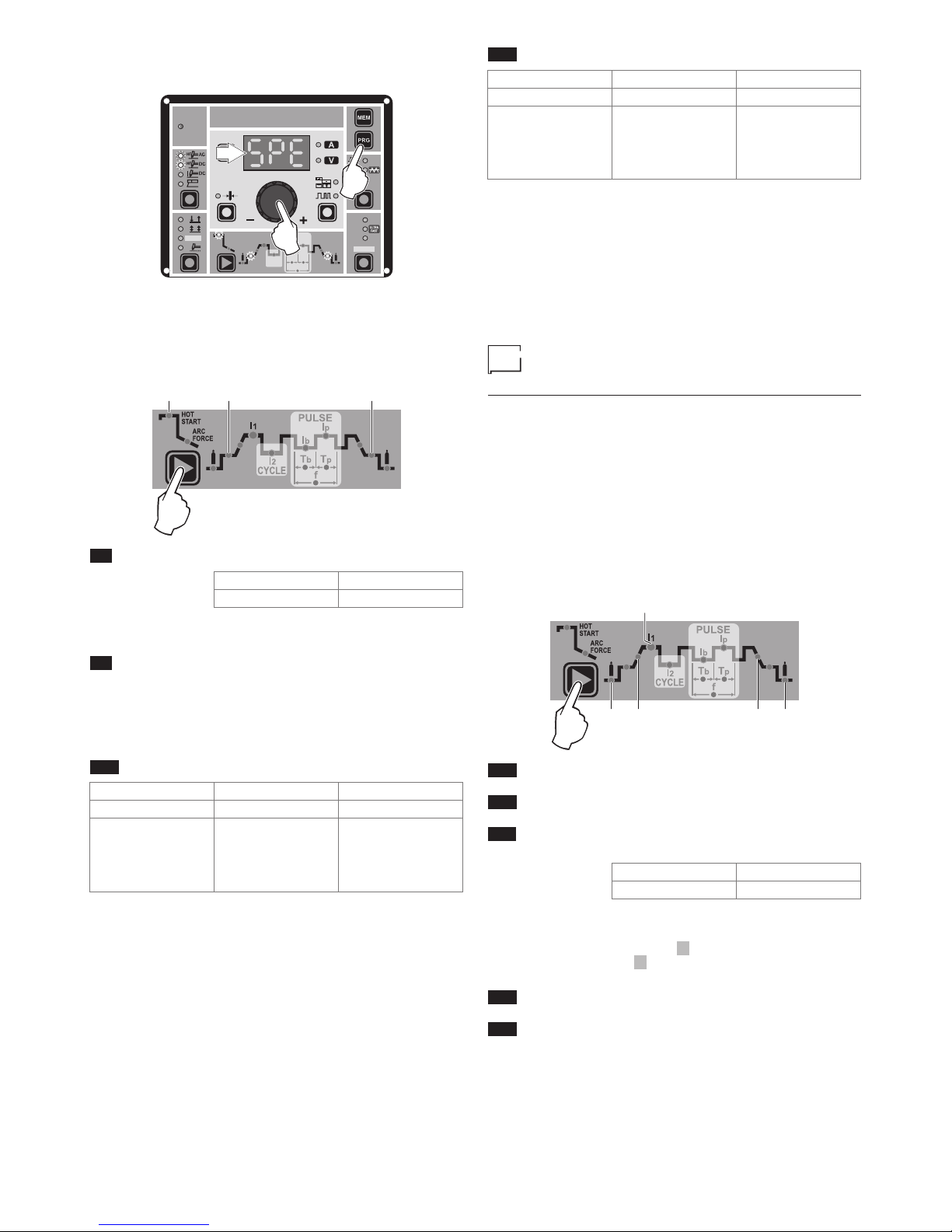
14
4) Turn the ENCODER Key (E) until the DISPLAY (D) shows
the following message: SPE (welder configured in SPECIAL
mode).
I2
HOT
START
ARC
FORCE
PULSE
CYCLE
T
b
f
T
p
I1
Ip
Ib
PULSE
SYN
FAST
SLOW
WAVE
VRD
CYCLE
Ø
T2
E
PULSE
SYN
FAST
SLOW
WAVE
D
E
T2
5) Press the “PRG” PROGRAM key (T2) to confirm.
The WELDING PARAMETERS included, that can be programmed
and changed (by turning the ENCODER knob) in the SPECIAL
(SPE) configuration, along with those in the STANDARD configuration, can be set by pushing the WELDING PARAMETER SELECTION button (T10) successively:
L9 L18 L22
T10
L9 IGNITION CURRENT
2200 AC/DC 3000 AC/DC
5 ÷ 220 A 5 ÷ 300 A
WARNING: This can only be programmed for TIG AC with HF ig-
nition - TIG DC with HF ignition welding processes.
L9 IGNITION TIME duration (t.01 (0,01 sec) -
t.50 (0,50 sec))
WARNING: This can only be programmed when the TIG AC with
HF ignition welding process is active.
WARNING: If the value of these 2 parameters is too low, this could
prejudice ignition.
L18 IGNITION welding CURRENT
2200 AC/DC 3000 AC/DC
TIG DC 5 ÷ 220 A 5 ÷ 300 A
TIG AC
DYNAMIC TIG
SPEED TIG
COLD TIG
SOFT TIG
5 ÷ 220 A
5 ÷ 220 A
16 ÷ 127 A
16 ÷ 156 A
5 ÷ 300 A
5 ÷ 300 A
5 ÷ 173 A
5 ÷ 212 A
WARNING: This can only be programmed when the TIG AC with
HF ignition or TIG DC with HF ignition welding processes and
the 2 STROKES welding mode are used.
L22 FINAL welding CURRENT
2200 AC/DC 3000 AC/DC
TIG DC 5 ÷ 220 A 5 ÷ 300 A
TIG AC
DYNAMIC TIG
SPEED TIG
COLD TIG
SOFT TIG
5 ÷ 220 A
5 ÷ 220 A
16 ÷ 127 A
16 ÷ 156 A
5 ÷ 300 A
5 ÷ 300 A
5 ÷ 173 A
5 ÷ 212 A
WARNING: This can only be programmed when the TIG AC with
HF ignition or TIG DC with HF ignition welding processes and
the 2 STROKES welding mode are used.
To exit the setting phase, hold the WELDING PARAMETERS SELECTION key (T10) down for about 1 second.
WARNING: These WELDING PARAMETERS are only to be acti
-
vated by qualified personnel, or those trained by technicians.
Editing the maximum and minimum
limits for welding parameters
Welding machine in STANDARD (Std) configuration:
In welding processes:
• TIG AC with HF ignition
• TIG DC with HF ignition
The MATRIX AC/DC makes it possible to activate modification of
the MAXIMUM AND MINIMUM LIMITS for some WELDING PARAMETERS thereby providing a more expert welder with a more
versatile welding machine.
Proceed as follows:
1) Switch on the welding machine holding down the WELDING
PARAMETERS SELECTION key (T10).
2) Press the WELDING PARAMETERS SELECTION Key (T10)
a number of times to set the limits for the following welding
parameters:
L11
L17L16L13L12
T10
L12 PRE-GAS duration (maximum limit settable from 1,00
to 2,50 sec)
L13 SLOPE UP duration (maximum limit settable from 5,00
to 10,0 sec)
L11 MINIMUM CURRENT for remote controls - minimum
limit settable:
2200 AC/DC 3000 AC/DC
5 ÷ 220 A 5 ÷ 300 A
WARNING: If the minimum limit setting (for the remote control
MINIMUM CURRENT) is greater than or equal to the value for the
PRINCIPAL welding CURRENT I1 , you will weld at the PRINCIPAL welding CURRENT I1 , irrespective of the setting you have
chosen for the remote control.
L16 SLOPE DOWN duration (maximum limit settable from
8,00 to 15,0 sec)
L17 POST-GAS duration (maximum limit settable from 10,0
to 25,0 sec)
To exit the setting phase, hold the WELDING PARAMETERS SELECTION key (T10) down for about 1 second. The values set are
now active and welding can begin.
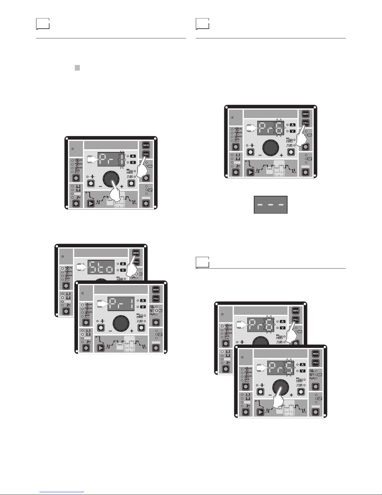
15
Creating and memorising
automatic welding points
Once you have defined the parameters the operator requires to do
their work properly, you can save them in the memory and create
a WELDING PROGRAM by proceeding as follows.
WARNING: To access the setting saving phase, the PRINCIPAL
CURRENT LED I1 must be switched on without flashing.
1) Hold the “PRG” PROGRAM Key (T2) down for at least 5 consecutive seconds until the DISPLAY (D) reads Pr, accompanied by a flashing number (e.g. Pr 1).
In order to be able to choose WELDING PROGRAM that is
free, simply rotate the ENCODER knob (E) and look for a program for which the control panel has all the LEDs for the various settings switched off.
WARNING: The MTA control panel allows you to save a max-
imum of 6 WELDING PROGRAMS.
It is also possible to overwrite a program already saved.
I2
HOT
START
ARC
FORCE
PULSE
CYCLE
T
b
f
T
p
I1
Ip
Ib
PULSE
SYN
FAST
SLOW
WAVE
VRD
CYCLE
Ø
PULSE
SYN
FAST
SLOW
WAVE
T2
D
E
2) To SAVE the PROGRAM hold the “MEM” SAVE Key (T1) down
until the DISPLAY reads “Sto”.
3) The WELDING PROGRAM has now been saved and its number appears in the DISPLAY (D) along with the other settings
saved (corresponding LEDs on without flashing).
I2
HOT
START
ARC
FORCE
PULSE
CYCLE
T
b
f
T
p
I1
Ip
Ib
PULSE
SYN
FAST
SLOW
WAVE
VRD
CYCLE
Ø
I2
HOT
START
ARC
FORCE
PULSE
CYCLE
T
b
f
T
p
I1
Ip
Ib
PULSE
SYN
FAST
SLOW
WAVE
VRD
CYCLE
Ø
PULSE
SYN
FAST
SLOW
WAVE
D
D
T1
PROGRAMMED and/
or MANUAL welding
PROGRAMMED WELDING
When the WELDING PROGRAM has been saved, the operator
can weld using only pre-set values as they cannot edit any type
of parameter / function. To edit, switch to MANUAL welding mode.
MANUAL WELDING
To go back to set / edit the parameters selected or to create a new
program, proceed as follows:
1) Hold the “PRG” PROGRAM Key (T2) down (about 3 seconds)
until the DISPLAY (D) shows the number of the program selected flashing (e.g. Pr6).
I2
HOT
START
ARC
FORCE
PULSE
CYCLE
T
b
f
T
p
I1
Ip
Ib
PULSE
SYN
FAST
SLOW
WAVE
VRD
CYCLE
Ø
PULSE
SYN
FAST
SLOW
WAVE
T2
D
2) Turn the ENCODER Key (E) anticlockwise until the DISPLAY
(D) shows 3 dashes.
3) Press and release the “PRG” PROGRAM key (T2) and the
machine goes back to the initial operation condition.
4) You can now set or edit the individual parameters or create
new programs.
5) Rotate the ENCODER Knob (E) to scroll the programs until
you find an empty, unused program slot.
Calling up saved programs
1) Hold the “PRG” PROGRAM Key (T2) down (about 3 seconds)
until the DISPLAY (D) shows the number of the program selected flashing (e.g. Pr 6).
2) Turn the ENCODER Knob (E) until the DISPLAY (D) shows
the program number (flashing) you wish to call up (e.g. Pr5).
I2
HOT
START
ARC
FORCE
PULSE
CYCLE
T
b
f
T
p
I1
Ip
Ib
PULSE
SYN
FAST
SLOW
WAVE
VRD
CYCLE
Ø
I2
HOT
START
ARC
FORCE
PULSE
CYCLE
T
b
f
T
p
I1
Ip
Ib
PULSE
SYN
FAST
SLOW
WAVE
VRD
CYCLE
Ø
PULSE
SYN
FAST
SLOW
WAVE
WAVE
T2
D
D
E
NOTE: If when you are rotating the ENCODER knob (E) to look for
a saved welding program to call up the MTA panel does not have
any LEDs switched on without flashing, this means that the welding program you are trying to call up has not been saved and, as
a result, cannot be called up!
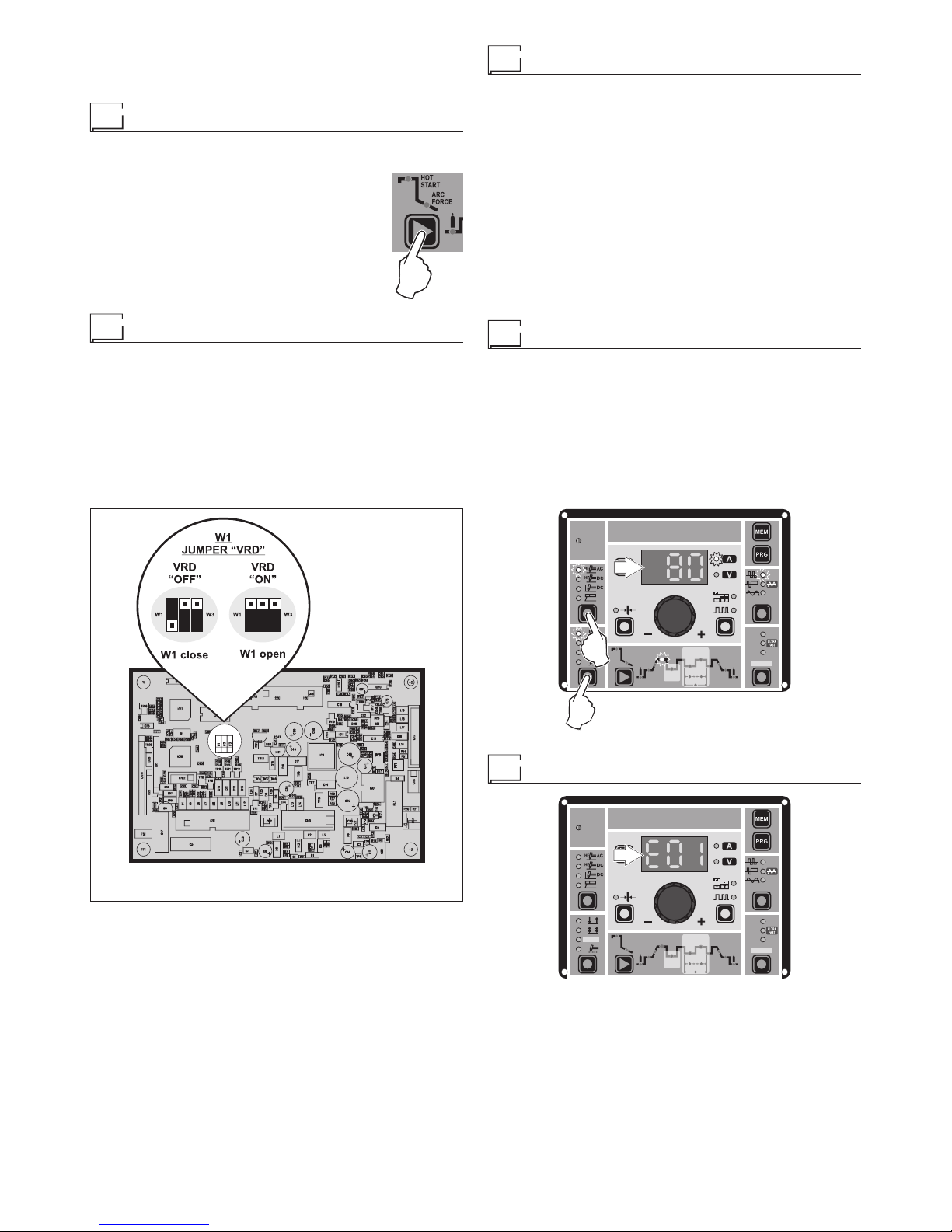
16
3) Press and release the “PRG” PROGRAM key (T2) to call up
the program number selected.
4) You can now carry out PROGRAMMED welding.
Viewing the parameters set
1) Call up the program required (see the “Calling up saved programs” paragraph).
2) Press and release the WELDING PARAMETERS SELECTION Key (T10) to view the parameters set in sequence.
3) Hold the WELDING PARAMETERS SELECTION Key (T10) down for more than 1 second
to go back to the program selected.
NOTE: If the parameters set are edited, you automatically exit programming.
Activating the VRD device
To activate the VRD device, which must be done when the welding machine is switched off:
1) Use a suitable screwdriver to unscrew the 4 screws that fix
the MTA control panel to the welding machine.
2) Position JUMPER W1 on the DIGITAL INTERFACE BOARD
in the correct position, following the instructions given in Figure A.
3) Use a suitable screwdriver to tighten the 4 screws that fix the
MTA control panel to the welding machine.
4) Start the welding machine by pushing the switch on the rear
panel to position I.
FIG. A
2000HB06
When the MTA control panel switches on the VRD LED will come
on and will be GREEN, which means that the VRD function is on.
To “deactivate” the VRD device and therefore start to weld, follow
this simple procedure: First touch the workpiece with the electrode, then detach it and ignite the arc within a MAX of 0,3 sec-
onds, otherwise if this time is exceeded the VRD device starts and
prevents welding.
During welding the VRD LED turns RED, which does not indicate
any malfunction on the welding machine, but that the VRD device
has been deactivated to allow welding.
T10
Auxiliary functions
“Energy saving”
This function manages correct functioning of the cooling fan and
cooling equipment that only run when strictly necessary, that is:
• FAN MOTOR - The fan is activated when:
-
During welding or for a certain period of time after this is finished.
-
When the thermostat intervenes or for a certain period of time
after it has just been reset.
• COOLING DEVICE - The cooling device is activated:
-
For a few seconds when the machine switches on. This oper
ation is used to make the cooling liquid circulate through the
plant at the correct pressure. Call the technical service department if, when the cooling system is switched off, the error
does not disappear from the DISPLAY (D).
-
During welding or for a certain period of time after this is finished.
Factory default
WARNING: This operation results in complete resetting of all pa-
rameters to the factory settings.
To reset the settings, you must:
• When the welding machine is off, push and hold the WELDING
PROCESS SELECTION (T7) and WELDING MODE SELECTION (T9) keys down together.
•
Switch on the welding machine and hold down the keys until the
DISPLAY (D) reads 80.
• Release the two keys.
• The reset procedure has now been completed successfully.
I2
HOT
START
ARC
FORCE
PULSE
CYCLE
T
b
f
T
p
I1
Ip
Ib
PULSE
SYN
FAST
SLOW
WAVE
VRD
CYCLE
Ø
PULSE
SYN
FAST
SLOW
WAVE
T9
T7
D
Error and protection conditions
I2
HOT
START
ARC
FORCE
PULSE
CYCLE
T
b
f
T
p
I1
Ip
Ib
PULSE
SYN
FAST
SLOW
WAVE
VRD
CYCLE
Ø
PULSE
SYN
FAST
SLOW
WAVE
D
The equipment is protected against problems and if any arise the
DISPLAY shows fixed or flashing (error code) messages (depending on the type of error) that serve to inform the operator that a fault
has occurred in the equipment (see table 1).
The table provides a summary of all the error conditions that may
arise on the equipment and, if possible, what the operator must
do to attempt to resolve the problem.
Automatic reset error: once the alarm condition has been resolved the equipment starts working again and the operator can
weld again!

17
PLEASE NOTE: If the fault persists look for the cause of the
fault and contact our technical assistance department if necessary.
All of this is necessary to allow our technical assistance department (which must be contacted each time error messages
appear on the equipment’s operator interface) to resolve problems more easily, as quickly as possible and thanks to the user’s
reports, also because, in the meantime the machine will not allow
the operator to do their work.
Table 1
Display Diagnosis
E01
PRESSURE SWITCH
This message appears when the cooling equipment
is connected to the machine and its pressure switch
does not close due to a lack of pressure in the
hydraulic circuit.
Automatic reset error.
E02
OVER VOLTAGE
This message appears when the power supply
voltage for the MATRIX 3000 AC/DC - AC/DC R
exceeds 500V.
If the fault persists look for the cause of the fault
and contact our technical assistance department if
necessary.
Automatic reset error.
E03
UNDER VOLTAGE
This message appears when the power supply
voltage for the MATRIX 3000 AC/DC - AC/DC R
drops below 280V.
If the fault persists look for the cause of the fault
and contact our technical assistance department if
necessary.
Automatic reset error.
t°C
THERMAL PROTECTION
The welding stops due to an excessively high
temperature (thermostat activated).
Automatic reset error.
WARNING: The MATRIX 2200 AC/DC welding machine has a
built-in electronic protective device to deal with fluctuations
in mains voltage that switches the machine off automatically (voltage exceeding 300 V), without indicating any type of
error or warning message for the operator. Subsequently it
starts functioning again automatically when the voltage has
dropped to below the value indicated above.

CEA COSTRUZIONI ELETTROMECCANICHE ANNETTONI S.p.A.
C.so E. Filiberto, 27 - 23900 LECCO - ITALY
Cas. Post. (P.O. BOX) 205
Tel. +39 0341 22322 - Fax +39 0341 422646
cea@ceaweld.com
www.ceaweld.com
ISO 9001: 2008
 Loading...