

4-Horse Panel Walker
Installation Instructions
Model 442
Includes New Touch Screen and Push Button Control Boxes,
Optional Drag and Spray Kit Assembly Instructions
HWP442_v4-0919
www.priefert.com 800-527-8616

Congratulations on choosing
“Priefert’s 4-Horse Panel Walker.”
Priefert Horse Walkers are attractive, durable, and oer more options than
ever before. Top equine professionals from around the world choose our
horse walkers for their reliability and the company that stands behind it.
Priefert products are used and tested in our manufacturing facility and on
the Priefert Ranch. The Priefert family personally tests and uses every
product they build before sharing it with their friends around the world.
Using this manual:
These Installation Instructions are a compilation of engineering data and
eld experience, and are designed to help you with proper installation,
safety, operation and adjustments. Read these instructions completely
prior to beginning assembly, and follow the recommendations to help
ensure safe and ecient operation.
The information contained herein was current at the time of printing. Your
model may vary in design and conguration from those shown in this
manual. There is a possibility that some illustrations in our manuals were
of prototype models. Design of production models may vary in detail from
those shown in our manuals.
Priefert Manufacturing maintains an ongoing program of continuous
product improvement. Therefore, Priefert reserves the right to make
improvements or modications in design, or specication changes without
incurring any obligation to replace said items on units previously sold.
Your 4-Horse Panel Walker comes with an instructional DVD and is also
available online in PDF format. Both have been designed to assist you in
achieving optimal results with your Horse Walker.
Terminology
“Priefert Equine...Unbridled Commitment”
REMEMBER SAFETY FIRST!
Be Alert - Eliminate unsafe habits and risky behavior,
recognize hazards as they exist and read and follow these
Installation Instructions to successfully assembly the
Priefert 4-Horse Panel Walker.
READ AND UNDERSTAND THESE INSTRUCTIONS
BEFORE BEGINNING INSTALLATION.
Follow all safety warnings and recommendations.
FCC Compliance Statement:
This device complies with part 15 of the FCC Rules.
Operation is subject to the following two conditions:
(1) This device may not cause harmful interference, and
(2) this device must accept any interference received, including interference
that may cause undesired operation.
NOTE: This equipment has been tested and found to comply with the limits
for a Class B digital device, pursuant to part 15 of the FCC Rules. These limits
are designed to provide reasonable protection against harmful interference
in a residential installation. This equipment generates, uses and can radiate
radio frequency energy and, if not installed and used in accordance with
the instructions, may cause harmful interference to radio communications.
However, there is no guarantee that interference will not occur in a particular
installation. If this equipment does cause harmful interference to radio or
television reception, which can be determined by turning the equipment o and
on, the user is encouraged to try to correct the interference by one or more of
the following measures:
—Reorient or relocate the receiving antenna.
—Increase the separation between the equipment and receiver.
—Connect the equipment into an outlet on a circuit dierent from that to which
the receiver is connected.
—Consult the dealer or an experienced radio/TV technician for help.
2
“NOTE:” provides the operator a brief summary of information that will
assist in operating the implement.
“IMPORTANT:” denotes that the following content has signicance in the
operation or maintenance of the implement.
Owner Assistance
If customer service or repair parts are required, contact Priefert
Manufacturing to reach our trained personnel who will assist you with
repair parts and equipment needed to service your Panel Walker. The parts
on your Panel Walker have been specically designed and should only
be replaced with genuine Priefert parts. Therefore, should your Priefert
Panel Walker require replacement parts, contact our Support Center.
Customer Service
Priefert Manufacturing wants you to be satised with your new 4-Horse
Panel Walker. If for any reason you are not satised with the equipment,
the following actions are suggested:
Contact your Priefert Ranch Equipment dealer and discuss any problems
that you may be experiencing. Allow them the opportunity to assist in
correcting any problems that you may be experiencing.
For further assistance contact:
Priefert Manufacturing
Attention: Customer Service
2630 South Jeerson
P.O. Box 1540
Mount Pleasant, Texas 75456-1540
1-800-527-8616
Web-site address:
www.priefert.com
sales.priefert.com
i
v4-0919

Safety
Safety Alert Symbols
The SAFETY ALERT SYMBOL indicates there is a potential
hazard to personal safety involved and extra safety precaution must be
taken. When you see this symbol, be alert and carefully read the message
that follows it. In addition to design and conguration of equipment, hazard
control and accident prevention are dependent upon the awareness,
concern, prudence and proper training of personnel involved in the operation,
transport, maintenance and storage of equipment.
Ow n er/op e rat o r can pr e v ent an d ma y be re s pon s i ble fo r ac ci d ent s or in jur i es
occurring to other people, themselves, and/or property and equipment.
Thoroughly read and understand the installation, operation, references and
other material supplied with the Panel Walker. If the installer or operator
cannot read English, it is the owner’s responsibility to explain this material
to them.
We strongly recommend that children are not allowed to operate
or play on this equipment. Do not allow untrained people to
operate or service equipment.
Installation / Operation Safety
• Read and understand the installation instructions completely before
beginning installation. Work in a clean, dry, level area.
• Make sure any individuals assisting with the installation of this
equipment understand the instructions as well. Priefert recommends
the use of good quality tools of the type noted in this manual.
• Priefert also recommends wearing personal protective clothing while
assembling this Panel Walker including gloves and safety glasses,
as well as, arm, leg, head and foot protection.
• Allow only trained, qualied individuals to operate forklifts, tractors,
loaders or other vehicles used during installations; and that those
individuals are familiar with the operation of the specic vehicle used
during installations.
• Operate equipment only during fair weather conditions.
• Disconnect power before performing any service or repairs to the
equipment. Remove all tools used during installation from equipment
before operation.
• Use care around and while handling support cables. Entanglement in
support cables can cause death or serious injury.
Horse Walker and Equine Safety
Due to the inherent dangers associated with equestrian activities, many
states have adopted statutes pertaining to the liabilities of horse owners,
handlers, and individuals involved in equestrian activities. Some states
also require that you post signs at your facility with the specic “Warning
Law” on them, for personal and/or professional equine activities. Posting
these warning signs may help protect you and/or your organization in the
event an accident or injury does occur. Please check the legal statute
information in your state.
Horses can be easily spooked and this is when injuries may occur. One in
three horse-related injuries happen when the rider/handler is dismounted.
These injuries typically involve the handler being kicked or stepped on by
the horse. Making sure all equine handlers are aware of the dangers posed
by frightened horses and what actions can scare them can help prevent
injuries. Some examples of things that can spook a horse include, sudden
or unexpected movements; loud or sudden noises such as mobile phones
or horns; other animals (i.e. unleashed and/or barking dogs) and biting
insects.
Priefert advises that horses not be saddled or tacked
when in the Walker, and recommends halters be removed
to prevent possible entanglement with moving parts.
Additional information is provided in the Appendix at the
end of this manual.
Safe Operation Guidelines
• Use caution introducing horses to the walker until the horse becomes
familiar with its operation.
• Do not let children play in or on horse walker or its components.
• Do not allow children to operate walker or its components.
• Do not sit, stand or climb on panels during operation
• Do not stick arms or legs through the panels while the walker is
in motion.
• Do not touch hanging panels while power is on; panels are electried.
• Make sure all guests or observers are clear of panels, gates and
moving components prior to walker operation.
• Be sure both inner and outer gates are closed before operating
walker. Never operate walker with gates open.
• Be sure the walker is completely stopped and power is o before
opening gates or entering the walker.
• Be cautious to prevent being conned between the panels whenever
horses are in the walker. Be cautious to prevent being caught
between the horse and panels.
• Be sure that horses introduced to the walker are only handled by
those familiar with equine behavior.
• Do not attempt to ride horses while in walker.
• Wearing proper clothing can help prevent injuries.
• Always take into consideration the age, physical condition and
specic characteristics of horses within the Walker to prevent
exceeding their limitations.
BE AWARE OF SIGNAL WORDS: A signal word designates a degree of level of hazard seriousness.
NOTE: Provides helpful information to the operator.
IMPORTANT: Indicates failure to observe may cause damage to
equipment.
WARNING: Indicates a potentially hazardous situation which, if not
avoided, could result in death or serious injury, and includes hazards that
are exposed when guards are removed. It may also be used to alert
against unsafe practices.
1. Sentry Insurance, FEMA, Owner’s and Operators Manuals for Farm Equipment, Sentry Insurance, Stevens Point, WI, revised Management Bulletin No. 112, 90-42;
March 2007, pp S-2.
v4-0919
1
CAUTION: Indicates an imminently hazardous situation, which, if not
avoided, may result in minor or moderate injury. It may also be used to
alert against unsafe practices.
1
DANGER: Indicates an imminently hazardous situation, which, if not
avoided, will result in death or serious injury. This signal word is limited
to the most extreme situations, typically for machine components that, for
functional purposes cannot be guarded.
1
ii
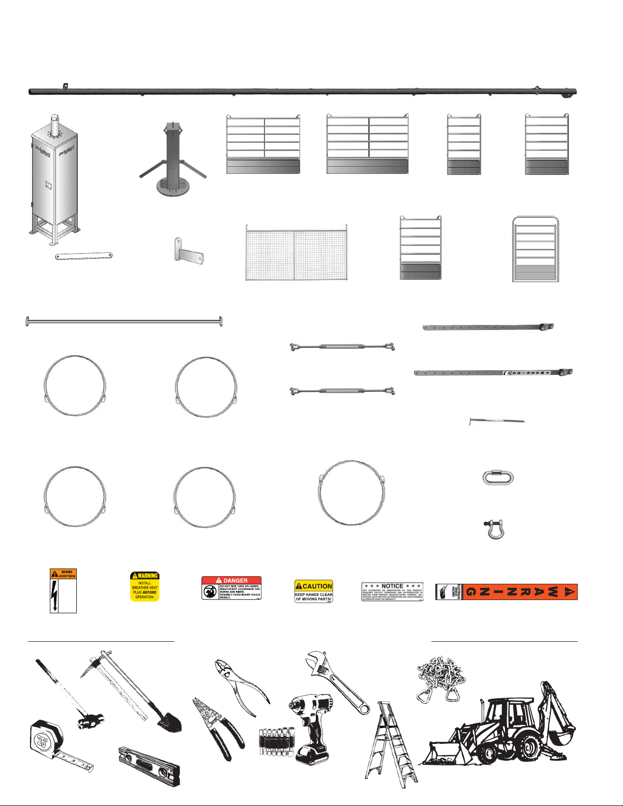
Parts List
Inner Arm (4ea)
Base
Assembly
(1ea)
HWBASE46-ASM
Tree (1ea)
HW4TREE-ASM
w/Support Straps
Support Strap (4ea)
HWPARMSTRAP
(attached to Tree)
Stabilizer Bar (4ea)
HWPS
HWINNERARM
Anchor Stake
Clip (28ea)
HWRPSC
Inner Panel (8ea)
HW4PCPSBI-8
Hanging Panel (4ea)
HWP
½" Turnbuckle (4ea)
Outer Panel (15e a)
HW4PCPSBO
3'-6" Panel (1ea)
HWPSP03.5SB
FMTB0812
Outer Arm (4ea)
HW4OUTERARM
2' Panel (1e a)
HWPSP02SB
5' BowGate (2ea)
Panel Strap - Short (4ea)
HWPARMS
4' Panel (1e a)
HWPSP04SB
HWRPBG
Inner Cables
/" x 162¼" (2ea)
CABLE0562.5-P
Outer Cables
/" X 302" (2ea)
CABLE05302-P
HIGH VOLTAGE AND ROTATING
PARTS CAN CAUSE SEVERE
INJURY OR DEATH.
1. TURN OFF AND LOCK OUT POWER
BEFORE SERVICE OR MAINTENANCE.
2. GROUND AND PROTECT PER
NATIONAL ELECTRICAL AND LOCAL
CODES.
3. KEEP ALL GUARDS IN PLACE.
ALTO VOLTAJE Y PARTES
ROTATIVAS PUEDEN CAUSAR
LESIONES SEVERAS O MUERTE.
1. APAGUE Y ASEGURE EL INTERRUPTOR
DE POTENCIA ANTES DE DAR
SERVICIO O MAINTENIMIENTO.
2. ALTERIZAR ARMAZÓN Y PROTEGER
SEGÚN CÓDIGOS ELECTRICOS
LOCALES Y NATIONALES.
3. MANTENGA TOGAS LAS CUBIERTAS
EN SU LUGAR.
Warning (1ea)
DOMNI
Inner Turnbuckle Cable
/" X 138¾" (2ea)
Outer Turnbuckle Cables
/" X 280½" (2ea)
Warning (1ea)
D325
Shovel & possibly
a Pickaxe
⅝" Turnbuckle (4ea)
FMTB1012
CABLE05138.75-P
Top Cable
CABLE05280.5-P
Danger (2ea)
D315
½" X 184/" (4ea)
CABLE08184.5-P
Caution (4ea)
D250
Tools & Equipment Required
Pliers
Notice (1ea)
Adjustable
Wrench
D125
Panel Strap - Long (4ea)
HWPARML
Anchor Stake (28ea)
RBSTAKE
" Quick Links (16ea)
FM06QL
½" Shackle (4ea)
C08AS
Warning (4ea)
D121
Chain or Heavy-Duty
Tie-Down Strap
Tape
Measure
Sledgehammer
Level
Wire
Strippers
Impact tted with ¾", /",
/"sockets
&
Ladder
Forklift or Front End Loader
v4-0919
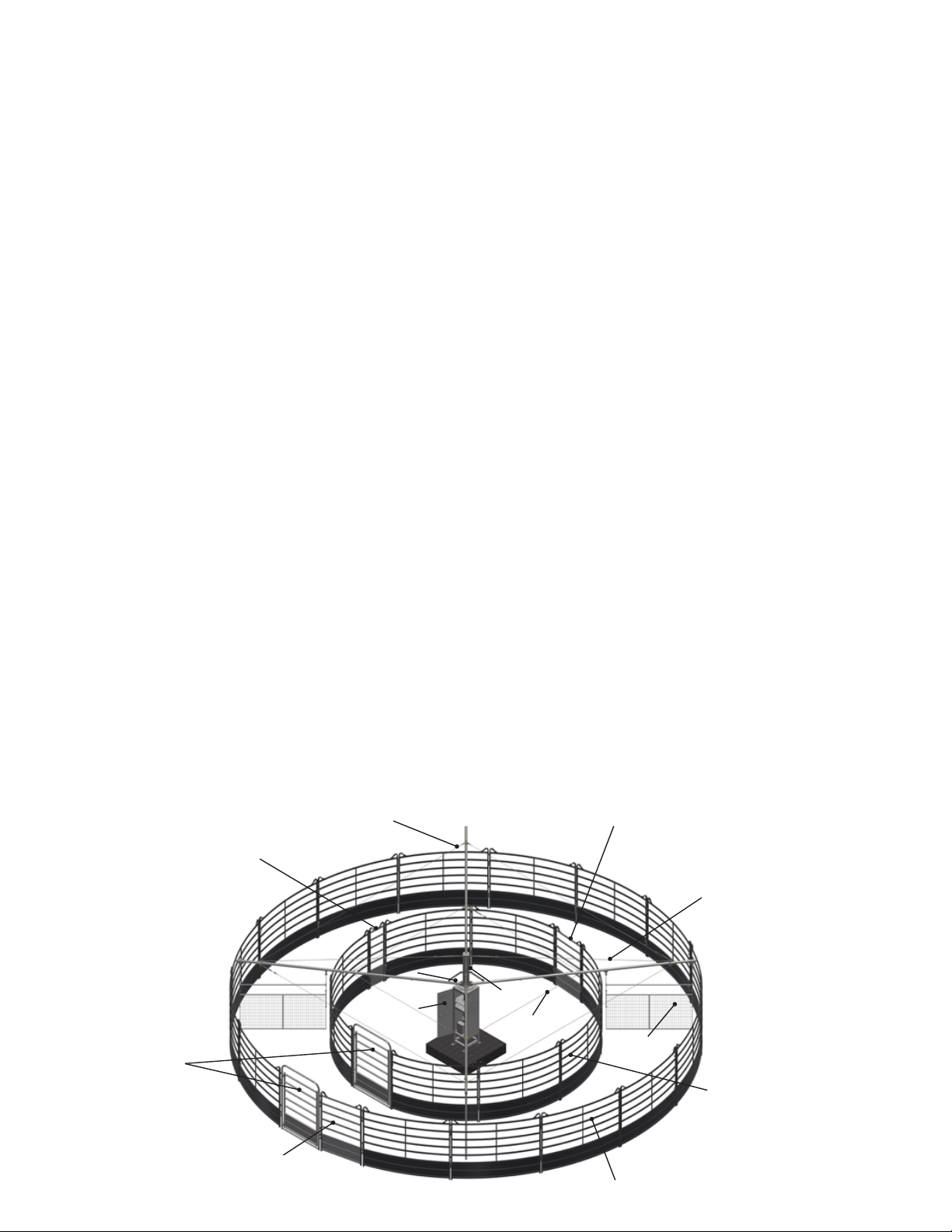
Table Of Contents
Congratulations. . . . . . . . . . . . . . . . . . . . . . . . . . . . . . . . . . . . . . . . . . . . . . . . . . . . . . . . . . . . . i
Using this Manual. . . . . . . . . . . . . . . . . . . . . . . . . . . . . . . . . . . . . . . . . . . . . . . . . . . . . . . . . . . . i
Customer Service Information. . . . . . . . . . . . . . . . . . . . . . . . . . . . . . . . . . . . . . . . . . . . . . . . . . . . ii
Safety . . . . . . . . . . . . . . . . . . . . . . . . . . . . . . . . . . . . . . . . . . . . . . . . . . . . . . . . . . . . . . . . . . ii
Safety Alert Symbols . . . . . . . . . . . . . . . . . . . . . . . . . . . . . . . . . . . . . . . . . . . . . . . . . . . . . . . . ii
Signal Words . . . . . . . . . . . . . . . . . . . . . . . . . . . . . . . . . . . . . . . . . . . . . . . . . . . . . . . . . . . . ii
Parts List . . . . . . . . . . . . . . . . . . . . . . . . . . . . . . . . . . . . . . . . . . . . . . . . . . . . . . . . . . . . . . . .iii
Tools & Equipment Required . . . . . . . . . . . . . . . . . . . . . . . . . . . . . . . . . . . . . . . . . . . . . . . . . . . . .iii
Concrete Pad Preparation . . . . . . . . . . . . . . . . . . . . . . . . . . . . . . . . . . . . . . . . . . . . . . . . . . . . . . 01
Pad Dimensions . . . . . . . . . . . . . . . . . . . . . . . . . . . . . . . . . . . . . . . . . . . . . . . . . . . . . . . . . . 01
Structural Anchor Bolt Jig . . . . . . . . . . . . . . . . . . . . . . . . . . . . . . . . . . . . . . . . . . . . . . . . . . . . . 01
Horse Walker Assembly . . . . . . . . . . . . . . . . . . . . . . . . . . . . . . . . . . . . . . . . . . . . . . . . . . . . . . . 02
Important Breather Plug Information . . . . . . . . . . . . . . . . . . . . . . . . . . . . . . . . . . . . . . . . . . . . . . 02
Setting Walker Base Assy . . . . . . . . . . . . . . . . . . . . . . . . . . . . . . . . . . . . . . . . . . . . . . . . . . . . . 03
Attaching Tree. . . . . . . . . . . . . . . . . . . . . . . . . . . . . . . . . . . . . . . . . . . . . . . . . . . . . . . . . . . 03
Installing Arms. . . . . . . . . . . . . . . . . . . . . . . . . . . . . . . . . . . . . . . . . . . . . . . . . . . . . . . . . . . 03
Attaching Top Cables . . . . . . . . . . . . . . . . . . . . . . . . . . . . . . . . . . . . . . . . . . . . . . . . . . . . . . . 04
Attaching Inner & Outer Cables . . . . . . . . . . . . . . . . . . . . . . . . . . . . . . . . . . . . . . . . . . . . . . . . . . 05
Dimensions For Round Pens . . . . . . . . . . . . . . . . . . . . . . . . . . . . . . . . . . . . . . . . . . . . . . . . . . . . 06
Clearances . . . . . . . . . . . . . . . . . . . . . . . . . . . . . . . . . . . . . . . . . . . . . . . . . . . . . . . . . . . . 08
Critical Dimensions . . . . . . . . . . . . . . . . . . . . . . . . . . . . . . . . . . . . . . . . . . . . . . . . . . . . . . . . 08
Hanging Panel Assembly. . . . . . . . . . . . . . . . . . . . . . . . . . . . . . . . . . . . . . . . . . . . . . . . . . . . . . . 07
Hanging Panel Mechanical Connections . . . . . . . . . . . . . . . . . . . . . . . . . . . . . . . . . . . . . . . . . . . . . 07
Hanging Panel Electrical Connections . . . . . . . . . . . . . . . . . . . . . . . . . . . . . . . . . . . . . . . . . . . . . . 11
Critical Dimensions. . . . . . . . . . . . . . . . . . . . . . . . . . . . . . . . . . . . . . . . . . . . . . . . . . . . . . . . . . 08
Round Pen Assembly. . . . . . . . . . . . . . . . . . . . . . . . . . . . . . . . . . . . . . . . . . . . . . . . . . . . . . . . . 09
Inner Ring Assembly . . . . . . . . . . . . . . . . . . . . . . . . . . . . . . . . . . . . . . . . . . . . . . . . . . . . . . . 09
Outer Ring Assembly . . . . . . . . . . . . . . . . . . . . . . . . . . . . . . . . . . . . . . . . . . . . . . . . . . . . . . . 10
Horse Walker Electrical Instructions . . . . . . . . . . . . . . . . . . . . . . . . . . . . . . . . . . . . . . . . . . . . . . . . 11
Control Panel Identication . . . . . . . . . . . . . . . . . . . . . . . . . . . . . . . . . . . . . . . . . . . . . . . . . . . . 12
Control Panel Contents Description . . . . . . . . . . . . . . . . . . . . . . . . . . . . . . . . . . . . . . . . . . . . . . . . 12
Basic Wiring Diagram . . . . . . . . . . . . . . . . . . . . . . . . . . . . . . . . . . . . . . . . . . . . . . . . . . . . . . . 12
Programming The Remote . . . . . . . . . . . . . . . . . . . . . . . . . . . . . . . . . . . . . . . . . . . . . . . . . . . . . . 13
Control Panel Description . . . . . . . . . . . . . . . . . . . . . . . . . . . . . . . . . . . . . . . . . . . . . . . . . . . . . 13
Programming Directions. . . . . . . . . . . . . . . . . . . . . . . . . . . . . . . . . . . . . . . . . . . . . . . . . . . . . . 13
Horse Walker Operation Instructions . . . . . . . . . . . . . . . . . . . . . . . . . . . . . . . . . . . . . . . . . . . . . . . . 15
Touch Screen Panel Functions . . . . . . . . . . . . . . . . . . . . . . . . . . . . . . . . . . . . . . . . . . . . . . . . . . 15
Screen Display Examples . . . . . . . . . . . . . . . . . . . . . . . . . . . . . . . . . . . . . . . . . . . . . . . . . . . .15-18
Push Button Control Panel Functions . . . . . . . . . . . . . . . . . . . . . . . . . . . . . . . . . . . . . . . . . . . . . . . 19
Optional Drag Installation . . . . . . . . . . . . . . . . . . . . . . . . . . . . . . . . . . . . . . . . . . . . . . . . . . . . . . 20
Drag Parts List. . . . . . . . . . . . . . . . . . . . . . . . . . . . . . . . . . . . . . . . . . . . . . . . . . . . . . . . . . . 20
Optional Spray Kit Installation . . . . . . . . . . . . . . . . . . . . . . . . . . . . . . . . . . . . . . . . . . . . . . . . . . . . 21
Spray Kit Parts List . . . . . . . . . . . . . . . . . . . . . . . . . . . . . . . . . . . . . . . . . . . . . . . . . . . . . . . . 22
Appendix . . . . . . . . . . . . . . . . . . . . . . . . . . . . . . . . . . . . . . . . . . . . . . . . . . . . . . . . . . . . . . . 23
OUTER CABLE
4' PANEL
v4-0919
BOW GATE
2' PANEL
3'-6" PANEL
BASE
ASSEMBLY
TREE
INNER
CABLE
CABLE
HANGING
PANEL
OUTER CURVED PANEL
TOP
INNER
CURVED
PANEL
iv

Concrete Pad Preparation
IMPORTANT: Be sure to select an area that is large enough to accommodate the Horse Walker Outer Ring with
sucient clearance all around. Area should also be level, and if possible, slightly higher than surrounding terrain
to allow drainage, but not excessive runo. Avoid low-level areas which could lead to ponding, puddles and
depositing of sediments. Level grading surface location prior to installation will produce the best results.
Panel Walker
and Lead Walker
Require
240 VAC 30 Amps.
See Page 11
for Electrical
Connections
Approx. 4” of conduit above pad.
NOTE:
Top of pad should
be ush with ground or 1" above.
HORSE WALKER CONCRETE PAD DIMENSIONS
Not to Scale
ADDITIONAL NOTE: If Optional Spray Kit is to be installed, waterline should be buried during this step of the
installation process. Priefert recommends Sch40 PVC buried below the freeze level for your location. Determine
the water supply location for the Spray Kit, and stub up and cap for that installation. (See Page 21)
1.
Concrete pad should follow the above specications.
60"
60"
We Strongly Recommend using the included
Structural Anchor Bolt Jig
2.
Walker Base Assembly will sit on an anchor bolt pattern of 18"x 22". The 18" side will be the front
side with the door. Overall diameter of walker to the end of the arms is approx. 42' (21' Outer Radius).
When placing the walker, keep the end of the arms 10' to 12' feet from any obstruction.
IMPORTANT: IF factory provided Anchor Bolt Jig is NOT used in installation, use INDUSTRIAL GRADE 3/4" anchor bolts.
01
v4-0919
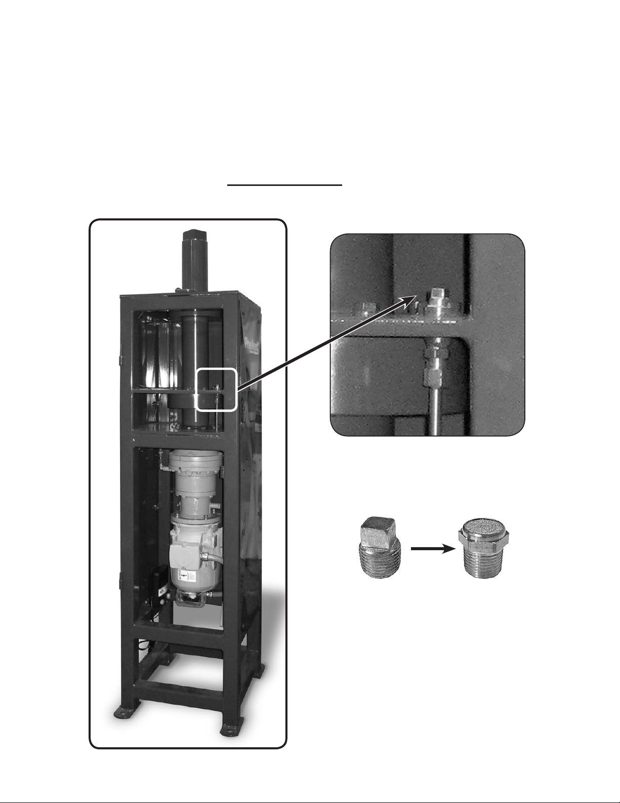
Horse Walker Assembly
Breather Installation
VERY IMPORTANT!
After locating and leveling Walker Base, Plug must be taken out & breather installed before power is turned on.
The breather is shipped inside the Control Panel with the Remote Control and Antenna.
Open Control Panel Box, remove breather and install BEFORE turning on Horse Walker power.
After locating and leveling
Walker Base
Replace
This
Shipping
Plug
The gearbox is pre-lled with
Lucas 75w140 Synthetic oil.
Priefert recommends changing the oil after
the rst 250 hours of operation. Oil should
be changed every 500 hours or each year of
operation thereafter, whichever comes rst.
Always replace with Lucas 75w140 Synthetic oil
With
This
Located
inside
Control Panel
Breather
v4-0919
or equivalent.
02
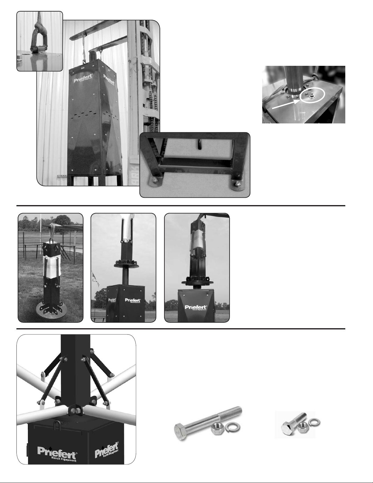
3.
To set the Base Assembly to the Concrete Pad, attach a chain
or strap to the lifting eyes on each side at the top of the Walker
Base and raise the walker with a forklift or front end loader.
NOTE: The Base weighs approximately 1200 lb. Be sure the
equipment used for lifting the Base is able to handle this
working weight.
USE CAUTION TO PREVENT
STRAP OR CHAIN DAMAGING
BRUSH ASSEMBLY
FOR HANGING PANELS
(See picture at right).
Make sure the walker is level,
put anchor bolt nuts on
and tighten.
REMINDER: BE SURE TO
INSTALL BREATHER
AS SHOWN ON
PREVIOUS PAGE
4.
To attach Tree, use a chain or strap
to attach to the lifting eye at the top of
the walker Tree. Pick up the Tree and
slide it over the main shaft.
When the Tree is all the way down,
rotate to make sure it slides down and
locks in place on the main shaft.
USE CAUTION NOT TO
DAMAGE BRUSH ASSEMBLY
AS SHOWN IN PREVIOUS STEP.
BRUSH ASSEMBLY WILL CONTACT
BASE OF TREE.
5.
To install the arms of the walker, attach the Inner Arms to the Tree
with the ⅞" x 5" bolts provided. Raise the Inner Arm and bolt it to
the Support Strap with the ⅝" x 1½" bolts.
Note: Do not install the nuts for the 7/8" x 5" bolts until all arms have been
installed. This will allow bolts to slide out to allow the next arm bolt
to be installed. Once all arms have been installed, then install and
tightened all nuts.
03
⅞
" x 5" Bolts used
to attach inner arm to
Horse Walker tree.
⅝" x 1½"
to attach support strap
from tree to inner arm.
Bolts used
v4-0919
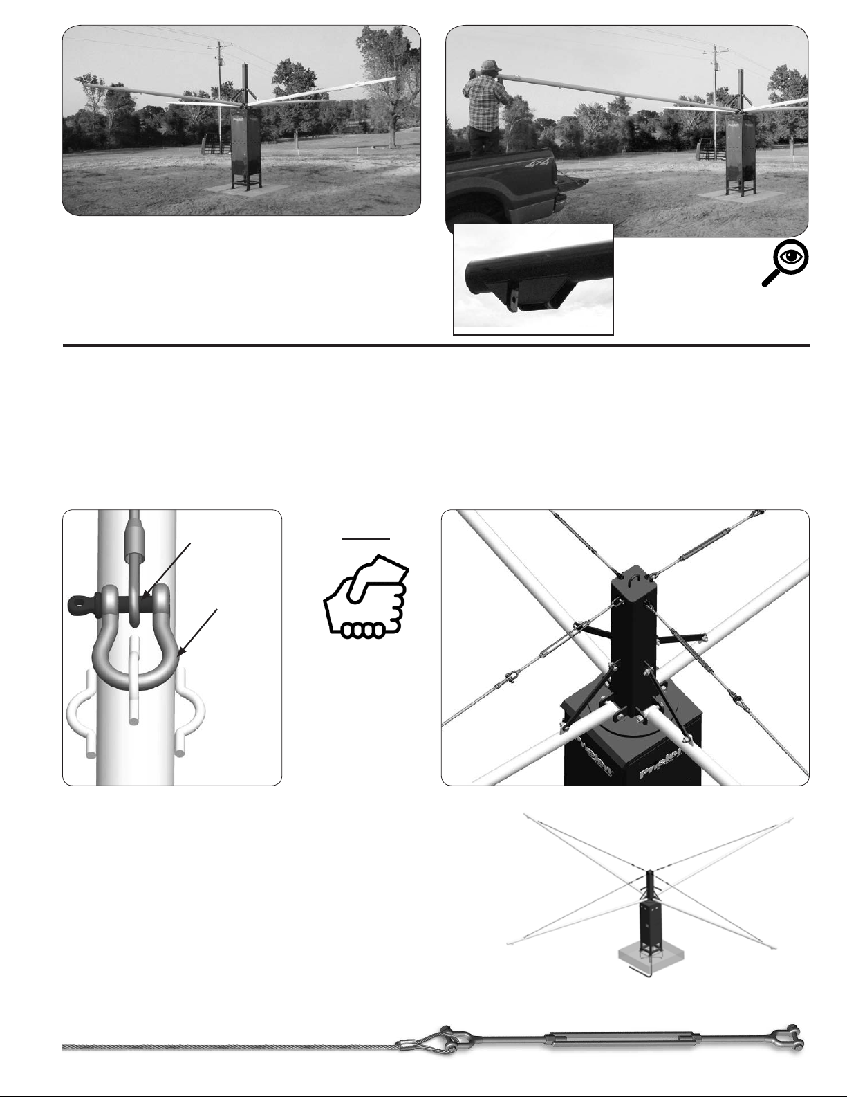
6.
Using the procedure in Step 5, attach all four
Inner Arms to the Tree.
Slide the end of the Outer Arm over the end of
the Inner Arm until the two pieces butt together.
7.
Locate the four ⅝" Turnbuckles, four 184½" (1/2") Top Cables and four ½" Shackles.
When installing
Outer Arms, be sure
mounting bracket
for Hanging Panel
faces down.
Attach the four top cables to the end of the outer arm with the ½" shackle.
Unscrew the four turnbuckles to the full extension.
Attach one end of the turnbuckle to the cable. Then, bolt the other end of the turnbuckle to the loop at the top of the tree.
This will require assistance from someone, or a lifting device, to raise the outer end of the arm to allow enough slack to
bolt the turnbuckle to the tree.
Top Cable Loop
½"
Shackle
Continue to attach top cables until all four arms are complete.
NOTE:
THESE STEPS
WILL BE
EASIER WITH
ASSISTANCE
OF ANOTHER
PERSON.
Tighten all of the Top Cables until there is a slight bow in the arm.
8.
Unscrew the four ⅝" Turnbuckles to the full extension.
Lay out the two 138¾" (5/16") Inner Turnbuckle Cables and
attach one end of the Turnbuckle to one end of each cable loop
as seen below.
Attach a ⅜" Quick Link to the other end.
v4-0919
04

9.
Lay out the two 162¼" (5/16") Inner Cables,
then attach to the loops at the center of the arms
by using the ⅜" Quick Links. These two cables
TURNBUCKLE
Inner
Turnbuckle
Cable
will attach between opposite arms on either side of
the Tree.
Inner
Cable
TURNBUCKLE
Inner
3/8" QUICK LINK
10.
Attach the two Inner Turnbuckle Cables from Step 8, between opposite arms using the ⅜" Quick Link on one end and
Turnbuckle
Cable
Inner
Cable
TURNBUCKLE
the Turnbuckle on the other. Reverse the location of the Turnbuckle on the opposite side. (See diagram above)
Tighten the Turnbuckles enough to remove the slack of all four inner cables.
NOTE: DO NOT FULLY TIGHTEN ANY TURNBUCKLES UNTIL ALL CABLES ARE ATTACHED!
OUTER TURNBUCKLE POSITIONED OPPOSITE OF INNER TURNBUCKLE
11.
Use the same procedures as in Step 9 & 10
to assemble the Outer Cables.
Lay out the two 302" (5/16") Outer Cables, then
attach to the loops at the ends of the arms by
using the ⅜" Quick Links.
12.
Lay out the two 280½” (5/16") Outer Turnbuckle Cables
and connect one ½" Turnbuckle to the loop in the end of
each cable.
Attach these two cables between opposite arms using a
Quick Link on one end and the Turnbuckle on the other.
These two cables will attach between opposite
arms on either side of the Tree as before.
Position the outer Turnbuckle opposite to the Turnbuckle
of the Inner Cables. (See above)
After all of the cables are in place, the top Turnbuckles
may need to be tightened again.
NOTE: WHEN TIGHTENING CABLES, BE SURE TO TIGHTEN TURNBUCKLES
UNIFORMLY TO PREVENT WARPING OR BOWING OF THE ARMS.
05
v4-0919

Dimensions for Inner & Outer Round Pens
40' - 2"
Clearance for
Hanging Panels
41' - 8"
Outer Curved Panels
Outer Pen:
HW4PCPSBO-15
HWRPBG-1
HWPSP04SB-1
TURNBUCKLE
25' - 0"
Inner pen:
HW4PCPSBI-8
HWRPBG-1
HWPSP03.5SB-1
HWPSP02SB-1
Be sure to use the proper anchoring methods in the following pages to insure a quality, professional installation for your
particular needs and requirements.
Inner Curved Panels
24' - 0"
SEE CRITICAL DIMENSIONS ON PAGE 08
v4-0919
Clearance for
Hanging Panels
±9'
06

Hanging Panel & Stabilizer Assembly
1. After all cables are tightened, bolt the panel straps to the mounting ears on the arms. The bolts
are assembled on the brackets of the Panel Straps. Remove the bolts from the end of the
brackets and install in the mounting ears on the arm. The short Panel Strap will go into the inner
mounting ear and the long Panel Strap will go into the outer mounting ear. (See examples pg. 08)
There are more holes in the outer strap then there are in the inner strap.
NOTE: Install the outer strap with the
“WARNING” label facing outward.
2. Install the Hanging Panel onto the Panel Straps you just assembled. With
the help of another person, lift the panel where the bottom of the panel is
16”- 20” o the ground. The panel must hang level. (See detail at bottom of
pg. 08). Use four ½” bolts & locknuts to attach. Be sure to note which holes
you used and bolt the remaining panels in the same position.
3. Allow a few holes above the Hanging Panel and attach the Stabilizer Bar
between the Panel Straps using four ½” bolts & locknuts. (See pg. 08)
4. After all panels are installed, you will need to adjust the top
cables to level the panels completely. Adjust turnbuckles on
every arm until they are exactly the same.
Allow 14'
minimum height
clearance from
Concrete Base
to any overhead
structure to
provide space
to assemble or
remove Tree
from Base
assembly.
Approximately 10'
overall height
5. Run the panel charger wire along the arm securing it to the
arm with the zip ties provided. Crimp one of the provided ring
Zip Tie
Panel Mounting
Brackets
ter mina ls o n th e inner end of th e
wire and attach to the nylatron
ring located on the bottom side
of the Horse Walker Tree using
¼" x ½" bolts. (See pg. 11)
Ring
Terminal
07
Crimp another ring terminal
on the other end of the
wire and connect it to the
Panel Strap using the
¼" x ¾" bolt, washer and nut.
See Page 11 for detail of Electrical Connections.
v4-0919

CRITICAL DIMENSIONS
STABILIZER BAR
Allow 1 or 2 holes above Hanging Panel
Approx. 4"- 6" clearance on Inner Ring
Approx. 7"- 9" clearance on Outer Ring
Make sure when assembling Round Pen that ample clearance is provided to allow Hanging
Panel to rotate freely inside. Location of Inner Ring and Outer Ring is very important for
proper operation of the Panel Walker. Review pages 06, 09 & 10 for proper clearances.
Panel Mounting
Brackets
±9'
Warning Label
Faces Outward
v4-0919
Be Sure Panel is Hanging Level
Begin with approximately 16" to 20" clearance
between ground and bottom of Hanging Panel.
It may be necessary to raise or lower Hanging Panel
to comfortably accommodate your horse
08

Round Pen Assembly
Read Before Beginning:
Determine location of Inner Bow Gate, and at 12' from center. R
hanging panel in-line with the hinge side of Bow Gate. Be sure to install an Anchor Stake Clip in the bottom of each
panel before locating and attaching panel. As you install the gate and curved panels, adjust the Round Pen panels
around until there is approx. 4"- 6" of clearance between the hanging panel and curved panel on the Inner Ring and
approx. 7"- 9" on Outer Ring, as shown on page 08, under Critical Dimensions. After the Bow Gate and rst curved panel
is in place, drive one Stake half-way into the ground, (Partially drive stakes to hold panels in place - you may have to
remove previously driven stakes for adjustments) going through the holes of the Anchor Stake Clips. Repeat as you work
your way around with curved and at panels until you work all the way around to the Bow Gate.
NOTE: Do not drive stakes completely into the ground until all panels are assembled and located to allow for adjustment if needed.
otate the Horse Walker Tree around until there is a
Inner Ring - First
1.
Locate position for the inner Bow Gate. Attach the Bow Gate to a curved Inner Panel
using the connector pins. Be sure the Anchor Stake Clips and the latching pins face
toward the center of the Horse Walker as shown in DETAIL A. Drive one Anchor Stake,
through hole in the clip, half-way into ground
Inside View
Outside View
ANCHOR STAKE CLIP
ANCHOR
STAKE CLIP
2.
Locate a second curved Inner Panel and attach it to the previous panel using the latching pins. Be sure you have
inserted the Anchor Stake Clip, and that it faces towards the center of the ring. As you are installing the panels,
manually turn the Horse Walker Hanging panel that is attached to the arm, rotating around to each panel to make sure
there is the proper clearance. After clearance is achieved, drive Stake through hole on Anchor Stake Clip, half-way into
ground as you work your way around.
3.
09
Outside View
ANCHOR
STAKE CLIP
Install two more curved panels, then
Study the diagram on the next page for
general locations for 2' & 4' at panels.
Continue installing panels around Inner
DETAIL A
IMPORTANT:
After the third or fourth curved panel,
connect the 4' panel. Adjust for proper
clearance as with the curved panels.
connect the 2' panel and again, adjust
for proper clearance.
Ring to meet the Latching pins on the
Bow Gate.
LATCHING PINS
v4-0919

2' PANEL
5' BOW GATE
Outer Ring - Second
4' PANEL
ATT ENTION:
TO ACHIEVE
PROPER CLEARANCE
AND SPACING,
BE SURE TO INSTALL
2' & 4' FLAT PANELS
OPPOSITE OF
BOW GATE, WITH
TWO (2) or THREE (3)
CURVED PANELS
IN BETWEEN.
4.
Following the procedure used for the Inner Ring, locate the Bow Gate for the Outer Ring, directly across from the
Inner Bow Gate at 20'-10" from center. Connect the at 3.5' Panel. Insert Anchor Stake Clip into bottom of panel leg.
Be sure the holes on the Anchor Stake Clip face outward, away from the center of the ring. After proper
clearance is achieved, drive a Stake through the hole on Anchor Stake Clip, half-way into ground as with the inner
ring. Connect a curved Outer Panel as with Inner Ring step 1. Place another Panel and continue around Outer Ring.
Again, manually turn the Horse Walker Hanging Panel around to each panel to make sure here is the proper clearance
around the entire outer ring.
REMINDER:
Only after all panels
are assembled, and
proper clearance is
achieved, drive all
anchor stakes fully.
v4-0919
10

Hanging Panel Electrical Connections
1.
Attach each electric wire to each panel by placing the
¼" x ¾" bolts and nuts provided through the drilled hole
on the Short Arm Attachment. (See Step 3 pg. 09)
NOTE:
Be sure enough
slack is given for
panel movement.
Swing Panel several
inches in each direction
to be sure there is ample
free-play in the wire.
2.
Attach the other end of each wire to the base of the Tree (See image above).
GREEN
TERMINAL
3.
Drive a 6’ ground rod beside the walker base and attach a #6 copper ground wire to
the ground rod and to the green terminal on the charger.
Horse Walker Electrical Connections
3
1
5
2
6
9
4
3
2
5
6
8
7
9
7
4
8
Touch Screen
Control Panel
10 11 12
8
Push Button
Control Panel
See following page for
full object descriptions
11
Terminal Strip
v4-0919

Horse Walker Electrical Instructions (cont.)
A certied electrician must install wiring and wire motor control.
Be sure to follow all electrical codes for your area.
WARNING:
PRIEFERT MANUFACTURING RECOMMENDS THAT ALL WIRE BE RUN THROUGH
ELECTRICAL GRADE CONDUIT TO PREVENT INJURY OR DEATH DUE TO ELECTROCUTION HAZARD
AND/OR DAMAGE TO EQUIPMENT.
CONTROL PANEL DESCRIPTIONS FROM PREVIOUS PAGE
1. 24v Power Supply
(Touch Screen Control Panel Only)
2. PLC
3. Motor Starter Relay
4. Line Reactor
5. Braking Resistor
6. 10 Amp Fuse
7. Motor Drive VDF
8. VDF Power Unit
9. Remote Receiver
10. Incoming Power (
See diagram above)
30amp double pole breaker from Main Power Supply - Four(4) #10 Wires
L1 Black - Hot; L2 Red - Hot; N White - Neutral; G Green - Ground
11. Outgoing Power To Charger (
See diagram above)
to Walker - Three(3) #12 Wires
L1 Black - Hot; N White - Neutral; G Green - Ground
12. Outgoing Power To Walker Motor (
See diagram above)
to Walker - Four(4) #10 Wires
T1 Black - Hot; T2 Red - Hot; T3 Blue - Hot; G Green - Ground
Basic Wiring Diagram
SHOULD HAVE 11 WIRES
AT CONTROL BOX
Four (4) #10 Wires IN
Four (4) #10 Wires OUT
Three (3) #12 Wires OUT
MAIN
POWER
SUPPLY
MAIN POWER SUPPLY
TO CONTROL BOX
Four (4) #10 Wires
Black - Hot
Red - Hot
White - Neutral
Green - Ground
CONTROL BOX
TO WALKER MOTOR
Four (4) #10 Wires
T1 - Black
T2 - Red
T3 - Blue
T4 - Green
TO FENCE CHARGER
Three (3) #12 Wires
G - Green
N - White
L1 - Black
WALKER /
WALKER BASE
v4-0919
12

The Remote Control for the Horse Walker comes
pre-programmed from the factory.
Programming is only necessary if additional, or replacement Remote Control is purchased.
Programming an Additional or Replacement Remote Control
for the Automatic Horse Walker
Read These Instructions Completely Before Beginning
Note: The circuit board allows for 4 seconds between pressing the Programming Button to activate the
function light, and pressing the corresponding button on the remote.
Tools required: Flat-head screwdriver and Phillips screwdriver.
Using a at-head screw driver, turn the two latch screws counter-clockwise to open the
Control Panel Box. Refer to Fig.1 for circuit board Box location.
Fig. 1
Circuit Board Box with
Cover Plate Removed.
Replace cover and secure
after programming remote.
Touch Screen
Control Panel
Push Button
Control Panel
Circuit Board Box (Fig. 1)
Using a Phillips screwdriver, remove the cover from the Circuit Board Box.
Turn on the power to the Control Panel. Top left Green Light on Circuit Board will be on
when power to Control Panel is ON.
See next page for Programming the Remote Control
NOTE: This equipment has been tested and found to comply with the limits for a Class A digital device, pursuant to part 15 of the FCC Rules.
13
2
v4-0919

REMEMBER: The circuit board allows for 4 seconds between pressing the Red Programming Button to activate
the LED function light, and pressing the corresponding button on the remote.
Press Red
1
Programming Button
Press and hold the red
Programming Button until
the 1st function light
(Red LED) comes on.
Immediately press the “O/1”
button on the Remote.
— the red LED light will blink.
Press Red
2
Programming Button
Press the red Programming
Button again,the 2nd function
light (Red LED) will appear.
Immediately press the “Faster”
button on the Remote.
—the red LED light will blink.
This Function
Light
will appear
(Red LED)
Then Press
this button on
the Remote
This Function
Light
will appear
(Red LED)
Then Press
this button on
the Remote
Press Red
3
Programming Button
Press the red Programming
Button again, the 3rd function
light (Red LED) will appear.
Immediately press the “Slower”
button on the Remote.
— the red LED light will blink.
Press Red
4
Programming Button
Press the red Programming
Button again, the 4th function
light (Green LED) will appear.
Immediately press the “Fwd/
Rev” button on the Remote.
— the green LED light will blink.
This Function
Light
will appear
(Red LED)
Then Press
this button on
the Remote
This Function
Light
will appear
(Green LED)
Then Press
this button on
the Remote
Your replacement Remote is now programmed to operate.
Wait for the four function lights to shut off before powering off the Control Box.
Replace the cover on the Circuit Board Box and close the Control Panel Box. You may now begin using your Priefert Horse Walker.
v4-0919
14

Horse Walker Operation Instructions
Display Panel
Charger Indicator
TOUCH SCREEN CONTROL PANEL
Stops
Horse Walker
Key Features on the Touch Screen Control Panel:
• 25 second “ramp up” time from start to the desired speed
setting helps ease horse into a walk.
• 25 second “ramp down” time from engage to full stop.
• Remote control that allows the operator to Start/Stop,
change direction (Forward/Reverse), as well as increase
or decrease speed; all with a push of a button.
• Convenient switch to allow low impedance electrical pulse
to hanging panels, encouraging horses to keep pace,
which can be turned o as horses become accustomed
to routines.
Charger ON/OFF
• Customized programming to set-up automated exercise
routines. Each routine can be programmed with up to
12 steps for changing pace, direction, etc.
• Flexibility to choose Programmed Routines or use the
Manual option.
Additional Features of the Touch Screen
The Start Screen appears after powering up the control panel.
Pressing the “MENU”
After 30 minutes, the display screen goes to screen-saver.
Touching returns to the last screen opened.
15
button accesses the functions of the Walker.
v4-0919

Section 1: MANUAL CONTROL Tab:
This tab displays the options for Manual Operation.
The Time and Speed of operation must be selected rst
•
Time can be set by touching 15 minutes , 30 minutes or
60 minutes . Touching button again will increase the time
to a maximum of 60 minutes. Time selected will appear in the
vertical indicator bar on the right, and Time Remaining will
count down when Walker is started.
•
Speed can be set by touching the up or down arrow buttons.
The up arrow increases speed, down arrow
speed. This will show as miles per hour (MPH) to a maximum
of 16.0 MPH. Tapping the speed indicating window will allow
manual entry of the desired speed.
•
Clockwise or Counter-Clockwise operation can be selected
by touching the Direction Button
. Direction can be changed
anytime during operation, Walker will ramp-down, stop, then
reverse and ramp-up again to the selected speed.
•
Once the Time and Speed has been selected, touching the
green start button
will begin operation, and walker will
ramp-up to the selected speed for the selected time.
Walker can be Paused or Stopped
any time during
operation, but the countdown time remains when paused.
Pressing Stop will Reset time to zero.
decreases
SET TIME
Options for Remote Control Operation.
Walker Operation Using the Remote Control Diers
from Manual Operation
•
If no time has been selected in Manual Operation, Time
will default to 15 minutes when "0/1" button is pressed for
3 seconds. Walker will ramp-up to the previously set MPH.
•
Pressing "Faster" will increase Walker speed,
pressing "Slower" will decrease Walker speed.
•
Change direction by pressing "Fwd/Rev".
NOTE: When Walker is operating, press and hold "0/1" for
three(3) seconds to pause Walker. Once paused, press and
hold the "01" button for three(3) seconds to restart.
START / STOP INCREASE SPEED
SET SPEED
SELECT DIRECTION
CHANGE
DIRECTION
v4-0919
DECREASE SPEED
REMOTE CONTROL FUNCTIONS
TOUCH START
16

Section 2: RUN ROUTINE Tab:
This tab displays the options for pre-set Routines.
Select a Routine by Touching the Pop-Up Menu.
•
Any Routine that has been set-up will appear in the
pop-up menu. Select the Routine to run and touch the
green START button.
•
Time duration and speed for each Step of the Routine will be
displayed on the right of the screen. PAUSE the Routine
at any time, then RESUME to continue the Routine.
Touch END
•
Priefert has provided a default Routine as an example of
to cancel the Routine.
how to set-up a simple warm-up. This or any Routine can
be revised to meet specic requirements. The next section
provides instructions to set-up a Routine.
Section 3: SET-UP ROUTINE Tab:
This tab displays the functions to Set-Up Routines.
Set-Up Routines with multiple Steps and durations.
•
Touch New Routine button . Key-in the name of the new
Routine to set-up. Touch the rst STEP
•
Touch, then key-in SPEED, TIME, select DIRECTION, then
touch Next to nish each STEP of the Routine, and move
to the next. Repeat this for additional steps in the Routine.
Touch END? to nish all Steps of the Routine.
Touch Save button , to save the Routine.
of the Routine.
SELECT ROUTINE
•
Any saved Routine can be changed or revised, then saved
as a new Routine by touching Save As
, then rename the
SET-UP ROUTINE
Routine. Use Delete to remove Routines.
•
The Routine Listing button allows Routines to be
renamed or listed sequentially
Section 4: MAINTENANCE Tab:
This tab displays the Maintenance functions.
Several functions reside in the Maintenance tab window.
•
MACHINE SETUP - This button opens a Login for service
technicians, and information set by Priefert only. It is not
needed for normal operation of the Walker or its functions.
•
CLEAN SCREEN - This button disables the Touch Screen
for 60 seconds to allow cleaning without activating other
functions of the Walker.
•
English / Español - Change language of Touch Screen.
•
ALARM HISTORY - This button displays alarms and faults
and allows them to be reset. See Section 5 for detailed information about alarms and faults.
•
START UP SCREEN - Returns to initial Start up screen.
MAINTENANCE FUNCTIONS
•
VIDEO - This button launches the media player application,
for future functionality, but is not currently active.
17
v4-0919

Section 5: MAINTENANCE Tab: ALARM HISTORY
This button displays Alarm History Information.
Alarms & Faults and How to Reset them.
•
FAULT ALERTS - This window will appear to alert that a
Fault has occurred. Several factors can lead to a Fault Alert
such as loss of communications or resistance due to horse
activity in the Walker. This condition of "Over-Torquing" will
cause a Fault Alarm.
The screen shown indicates that the horse(s) in the Walker,
prevented the Walker from turning freely numerous times
within a short period. Touching the RESET button will
usually clear an error of this type.
•
Faults will be recorded and logged in the Alarm Notication
window. If the RED diagnostic notication is visible, the
Fault must be resolved. This Fault will be noted in the
window to assist in solving the condition that caused the
error. The diagnostic notication will turn GREEN when the
Fault is resolved.
•
VIEW ALARM HISTORY - This button shows if a condition
has occurred numerous times to assist in resolving Faults or
preventing errors.
If for any reason an Alarm or Fault can not be solved or will
not reset, call Priefert for additional technical assistance.
FAULT ALERT
Section 6: MAINTENANCE Tab: VIDEO
This button activates the Media Player Application.
ALARM NOTIFICATION
Currently this performs no function.
•
Priefert Manufacturing is constantly advancing the
funtionality of its products. As improvements are made,
Priefert will update our manuals to reect these revisions.
More information can found on the web at:
http://www.prieferthorsewalkers.com/
or by calling toll-free: 1-800-527-8616 during regular
business hours..
VIDEO PLAYER
Never leave horses unattended while using Horse Walker.
v4-0919
18

Horse Walker Operation Instructions
PUSH-BUTTON CONTROL PANEL
15, 30, & 60
Minute Timer
Start/Stop
Forward/Reverse
Stops
Horse Walker
Key Features Fault / Reset
Speeds Up
Horse Walker
Slows Down
Horse Walker
Fault / Reset
• 25 second “ramp up” time from start to
desired speed setting to ease horse into walk.
• 25 second “ramp down” time from engaged
to stop.
• One of the more unique and outstanding
features of this lead walker is the fact that if
a horse balks and stops the walker, there is
no stress wear on the drive train. The motor
simply pauses and then restarts. Horses
soon respond to the “pressure and release”
training and therefore adapt to the Priefert
walker with less resistance and no negative
impact on the walker itself.
Horse Walker is programmed to require
“reset” if animals stop the walker more than
10 times within 60 seconds, or if the horse
is able to stop the walker for a sustained 10
seconds.
When fault light is illuminated, press and hold
FAULT button for a minimum of 2 seconds. If
fault light does not go o and walker does
not reset, contact Priefert at 1-800-527-8616.
No Belts To Burn!
Never leave horses unattended while using Horse Walker.
19
v4-0919

Optional Horse Walker Drag Installation
The Optional Horse walker Drag will help maintain a stable and uniform base-surface inside the Horse Walker
Ring. This can help prevent injury from uneven, low and/or slippery areas due to accumulation of rain water
and runo, and will smooth, distribute and level berming along the panels. Regular use of the drag will ensure
the best conditions for equine safety, well-being and peak performance.
CAUTION:
• Do not enter the walker while Drag is in operation.
• Be sure gates are closed while using the Drag.
• Do not stand on the Drag during operation.
• Do not allow anyone to ride on the Drag.
The Horse Walker Drag is designed to operate in either direction within the walker ring. Proper installation
will allow for relatively quick base-surface touch-ups with regular use. The directional-X design of the drag
provides the ability to distribute material where it is most needed.
1.
Determine Location
After completing the assembly of the walker and round pen, choose a hanging panel
that will be used for the drag. This will be the panel the drag will always attach to.
Components will remain on the panel for easy attachment of the drag.
Locate the HW Drag Chain Plate, Flat Backing plate, three (3) bolts and nuts.
These will attach to the bottom of the selected panel, 3 squares in from the outer
edge. Attach with bolts and nuts (See Fig.1).
Insert one (1) Spring Clip through the last link of a length of Chain and
clip to the plate. Move the remainder of the chain to the edge of the panel.
Repeat for other plate.
2.
Attach Drag
• Do not use the Drag with horses in the walker.
• Unclip and remove the Drag and Chains from the
walker ring immediately after use.
• Remove the accumulations of grass, rocks or other
debris after dragging to prevent tripping hazards.
HW Drag Chain Plate &
Backing Plate Assembly
SPRING CLIP
3 SQUARES
}
Fig.1
Place the Drag in the center of the Horse Walker ring. Study the picture below and notice the directional-X design of the Drag.
The long “X” end of the Drag pulls the base material in from the edge. The short “X” end spreads and levels the base material.
If the base material has built-up along the outer panels, locate the Drag with the long “X” end facing out (See Fig.2).
If the base material has deposited along the inner panels, turn the Drag around so the long “X” faces in. This feature allows
pulling the base material back into the center with even distribution.
When attaching the Chain to the Drag,
allow just enough length in the Chain for the
leading edge of the Drag to align with the
panel. Insert a Spring Clip through a link and
clip to the inner-side, center eyelet. Then,
on the outer Chain, add an additional 6-8
links of slack so the Drag will pull at a slight
angle. This slight angle will help stabilize the
Drag, and allow dragging in either direction.
Then insert a Spring Clip through a link
and clip to the outer-side, center eyelet.
Again, study the diagram for clarity.
FM06SC (4ea.)
HWDC-P (2ea.)
HW Drag Chain Plate
" Spring Clip
Short “X” End
Fig.2
Parts List
Center Eyelet
FB061.00ZPG5 (6ea.)
" x 1" Bolt
Long “X” End
FN06ASLN (6ea.)
" Fastener Nut
}
Allow 6 - 8
Extra Links
of Slack on
Outer Chain
v4-0919
FS031.25011.5-P (2ea.)
Flat Backing Plate
HWDRAGOB (1ea.)
Horse Walker Drag
C100.96 (2ea.)
" Chain 96 Links
20

Optional Spray Kit Installation
Inner Ring
Bow Gate
4’ Panel
Inner Ring
Panels
Nozzle
+ Tee
Nozzle
+ Tee
Nozzle
+ Tee
Nozzle
+ Tee
Nozzle
+ Tee
Nozzle
+ Tee
Nozzle
+ Tee
Nozzle
+ Tee
Nozzle
+ Tee
Nozzle
+ Tee
Nozzle
+ 90˚
Nozzle
+ 90˚
Water Supply
Tee
Outer Ring
Panels
Poly Tubing
Poly Tubing
STANDARD SPRAY KIT
NOZZLE & CONNECTOR
LOC ATIO N
USE THIS DIAGRAM FOR REFERENCE ONLY
NOT TO SCALE
BEGIN ASSEMBLY HERE
Be sure to have a licensed plumber facilitate connections of the water supply. Stub-up waterline where the Water Supply
Tee will be located to enable connection. Priefert recommends 3/4" Sch40 PVC, sand sheathed, buried below freeze level.
After completing the assembly of the walker and round pen, determine a location closest to the water supply.
Preferably, the water supply will be installed during the concrete pad preparation. This allows waterline to be run
at the same time as electrical conduit (pg. 1).
If necessary, a water supply may need to be brought to the location of the Horse Walker. If this is the case, water supply
will have to be buried beneath the walker panels and dirt base.
1. Prepare The Nozzles
Unpack and identify all parts before beginning.
Assemble ten (10) Spray Nozzles (See Diagram 1).
Locate Poly Tube and cut ten (10) sections, 2" long.
Insert assembled Spray Nozzles fully into one end of each.
Locate eight (8) PVC Tee ttings and insert into the other end of eight (8) of the tubes on the Spray Nozzles.
Diagram 1
Locate two (2) PVC 90˚ ttings, and insert them into the remaining two (2) Spray Nozzle tubes.
Locate the one (1) remaining Tee tting. This will be used for the connection to the water supply.
Spray Kit installs on the Inner Ring,
along the rail at the top of the solid
Diagram 2
(6-Horse layout shown)
section of each panel, Nozzles facing
outward. (See Diagram 2)
2. Assemble The Tubing
Begin by determining where the closest panel
connection is to the water supply. This will be
the starting point to run tubing and nozzles from.
Preferably, this will be opposite of the Bow Gate
or generally centered between the two ends of
the nished tubing assembly (See Diagram 2).
Connect the remaining Tee tting to one end of
the Tubing. This Tee will connect to the main
water supply from the Anti-Siphon valve.
Attach to the rail at the top of the solid section
of the panel with supplied, self-tapping, sheet
metal screw and Tubing Strap (See Diagram 3).
Use three to ve Tubing Straps per panel to hold Tubing securely. Some adjustment may be necessary after completing
assembly. Add Tubing Straps as needed.
21
Note: Temporary tment can be done with plastic zip-ties.
v4-0919

Optional Spray Kit Installation (cont.)
Run Poly Tube around to the stay at center of panel and cut.
Insert one of the Tee/Nozzle assemblies into that end and attach
Poly Tube to the other side of Tee/Nozzle assembly. Attach to
panel with screw and bracket (See diagram 3 inset).
Again, run hose around to next panel center stay and cut. Insert
another Tee/Nozzle assembly into the hose, attach hose to other
side of Tee/Nozzle assembly.
Zip-ties may be used to hold the tubing to the
Inset
panel during assembly.
Tubing
Strap
Continue this process around to the last panel
center stay before the Bow Gate. For the last
panel, insert the PVC 90˚/Nozzle assembly into
Self-Taping Screw
the Poly Tube instead of a Tee. Attach to the
panel as before.
Repeat this process to run the Poly Tube around the opposite direction from the Water Supply Tee at the starting point.
center stay
Tubing Straps
Diagram 3
3.
Attaching Water Supply
Before connecting the Anti-siphon valve and Timer, a ow test should be done to check for leaks or obstructions.
A ½" nipple connector is provided to attach a common garden hose to the tubing to check for any problems prior to nal
waterline connections.
After verifying all connections, determine the location for the anti-siphon valve and timer. Convenient locations near the Walker
Control Box is recommended, but not required. The anti-siphon valve is controlled by the timer and must be in-line with the main
water supply to the Spray Kit assembly. (See diagram 4)
Read assembly instructions included in the Anti-Siphon Valve package, and the instructions in the Timer package to determine
the best assembly options to meet your specic needs. If you have and uncertainties as to wiring or plumbing connections,
please have a qualied professional perform the installation.
PROGRAM
RAIN DELAY
RESET
Waterline Must Run Underground
Beneath Walker Base and Panels
From Main
Water Supply
To Supply Tee
on Spray Kit
PVC Tee (10ea.)
PVCTEE5.5.5
Self-Tapping Bolt (48ea.)
FB040.75ZPG2ST
Water Hose Swivel (1ea.)
BRASS08HB-12FWH
v4-0919
PVC 90° (1ea.)
PVC90-08HB-08HB
One-Hole Strap (48ea.)
RRC0.5ZP
Nozzle Body (10ea.)
NOZZLE BODY90
Nozzle Cap (10ea.)
NOZZLE CAP
Parts List
Nozzle Tip Strainer (10ea.)
NOZZLE STRAINER
Nozzle Tip (10ea.)
NOZZLE TIP
Poly Tubing (1ea.)
PT08ID10OD
RESET
Timer (1ea.)
HWPSK-TIMER
PROGRAM
RAIN DELAY
Anti-Siphon Valve (1ea.)
HWPSK-VALVE
22

References
1. Sentry Insurance, FEMA, Owner’s and Operators Manuals for Farm Equipment, Sentry Insurance, Stevens Point, WI, revised Management Bulletin No. 112, 9042; March 2007, pp S-2.B
2. https://apps.fcc.gov/kdb/GetAttachment.html?id=tz8CzcfpIVA2%2BognLZYTgA%3D%3D&desc=784748%20D01%20general%20labeling%20and%20
notication%20v09r01&tracking_number=27980
Federal Communications Commission, Oce of Engineering and Technology Laboratory Division, General Guidelines For Labeling And Other Information
Required To Be Provided To Users, Washington, DC; July 2018.
Suggested References
• https://www.equisearch.com/guides EQUISEARCH - Free Guides relating to Horses, Horse Health and Horse Care
• http://www.horsefeedblog.com/tag/equine-safety/ The Feed Room - Resources and Insights for Happy, Healthy Horses
• https://www.thespruce.com/working-safely-with-horses-1885951 The Spruce - Working Safely With Horses
• http://safe-wise.com/wp-content/uploads/2015/04/EquineSafetyManual.pdf Gillingham & Associates - Equine Safety Manual, Insurance Risk Management
• http://www.americanequestrian.com/equinelaws/ American Equestrian Alliance - State Equestrian Liability Limitation Laws
Appendix
Equine Activity Liability Act (EALA)
The following is a list of the 47 states which have adopted the Equine Activity Liability Act (EALA):
Alabama (Code of AL 1975 §6-5-337), Alaska (Alaska Statute § 09.65.145), Arizona (AZ Rev. Stat. §12-553), Arkansas (AR Code Ch. 120, §16-120-201),
Colorado (CO Rev. Stats. §13-21-119), Connecticut (CT Gen. Stat. Anno. § 52-557p), Delaware (1995 DE Code Title 10, Ch. 81, §8140), Florida (1993 FL Laws
Ch. 93-169, §773.01), Georgia (Code of GA Anno. §62-2701), Hawaii (1994 HI A.L.S. 249), Idaho (ID Code 1990 Ch. 18, §6-1801), Illinois (745 ILC.S.A. §47/1),
Indiana (IN Stat. Anno. §34-31-5-1), Iowa (IA Code Anno. §673.1), Kansas (1994 KS A.L.S. 290), Kentucky (KY Rev. Stat. §247.401), Louisiana (LA Rev. Stat.
§9:2795.1), Maine (ME Stat. Title 7 §4101), Massachusetts (MA Gen. Laws 128 §2D), Michigan (MI C.L. §691.1661), Missouri (MO R.S. §537.325), Minnesota
(MN Ch. 623, Art 3§2), Mississippi (MS Code Anno. §95-11-1), Montana (MT Code Anno. §27-1-725), Nebraska (Rev. Stat. of NE §25-21, 249), Nevada (NRS
41.480), New Hampshire (NH Rev. Stat. Anno. §508:19), New Jersey (NJ Stat. 5:15-1), New Mexico (NM Stat. Anno. Art. 13, §42-13-1), North Carolina (Gen.
Stats. Of NC, ch. 99E, art. 1), North Dakota (ND Code §53-10-1), Ohio (OH Rev. Code §2305.32.1), Oklahoma (OK Stat. Title 76 §50.1), Oregon (OR Rev. Stat.
§30.687), Pennsylvania (P.L. 472, No. 93, § 601-606), Rhode Island (RI Laws Ch. 21, §4-21-1), South Carolina (SC Laws §47-9-710), South Dakota (SD Laws
Anno. §42-11-1), Tennessee (TN Code Anno. §44-20-101), Texas (TX Code Anno. §87.001), Utah (UT Code Anno. §78-27b-101), Virginia (VA Code Ch. 27.5,
§3.1-796.130), Vermont (12 VT Stat. Anno. § 1039), Washington (WA R.C.W 4.24.530), West Virginia (WV Code Art. 4 §20-4-1), Wisconsin (WI S.A. §895.481),
Wyoming (WY Stat. §1-1-122).
Note that this list is accurate only at the time of publication, and may have revisions beyond that time period. Please make it your responsibility to research laws
pertaining to your state or province.
23
v4-0919

Limited Warranties:
Priefert Manufacturing Company, Inc., (“Priefert”) 2630 South Jeerson, P.O. Box 1540, Mount Pleasant, TX 75456-1540,
warrants for one (1) year from the purchase date to the original non-commercial, governmental, or municipal purchaser
(“Purchaser”) and warrants for six (6) months to the original commercial or industrial purchaser (“Purchaser”) that the product
purchased are free from defects in material or workmanship. Priefert will replace or repair, free of charge to the original
purchaser any part(s) found, upon examination at our factory, to be defective under normal use and service due to defects in
material or workmanship, provided that the original purchaser:
a. Noties Priefert in writing of any defect in material or workmanship within the above specied warranty period.
b. Returns must be routed through an authorized Priefert dealer or distributor from whom the purchase was made.
c. Purchaser is responsible for cost of shipping.
In no event will Priefert be held liable under this warranty unless written notice is received and failure must have occurred
within the warranty period. Genuine Priefert replacement parts and components will be warranted for 90 days from date of
purchase, or the remainder of the original equipment warranty period, whichever is longer.
is limited warranty does not apply to any part of the product which has been subjected to improper or misintended use,
negligence, alteration, modication, or accident, damaged due to lack of maintenance or use of wrong oil or lubricants, or
repairs that have been made with parts other than those obtainable through Priefert, or which has served its usual life. is
limited warranty does not apply to any expendable item such as blades, shields, guards, or pneumatic tires, or other trade
accessories since these items are warranted separately by their respective manufacturers, except as specically noted in your
Operator’s Manual.
Except as provided herein, no employee, agent, Dealer, or other person is authorized to give any warranties of any nature on behalf
of Priefert. Only Priefert is authorized to make any representation to the purchaser concerning “normal” use and service for its
product as described in the Operator’s Manual, or in authorized printed materials or stickers axed to the product.
If aer examination of the product and/or part(s) in question; Priefert nds them to be defective under normal use and service
due to defects in material or workmanship,
Priefert will:
1. Repair or replace the defective product or part(s); if Priefert has made several reasonable number of attempts in repairing
the product and/or part(s) to conform to the warranty; then
2. Priefert will replace part(s) or product.
3. Purchaser is responsible for any labor charges exceeding a reasonable amount as determined by Priefert and for returning
product and/or part(s) to the Dealer, whether or not the claim is approved. Purchaser is responsible for the transportation
cost for the product or part(s) from the Dealer to the factory.
e choice of remedy shall belong to Priefert. Repair or replacement are the only remedies against Priefert under this limited
warranty.
Limitation of Liability:
1. Priefert disclaims any express (except as set forth herein) and implied warranties with respect to the product including, but
not limited to, merchantability and tness for a particular purpose.
2. Priefert makes no warranty as to the design, capability, capacity, or suitability for use of the product.
3. is warranty shall not be interpreted to render us liable for injury or damages of any kind or nature to person or property.
Priefert will not be liable for any special, incidental or consequential damages based upon breach of warranty, breach of
contract, negligence, strict tort liability, or any other legal theory. Such damages include but are not limited to loss of crops,
loss of savings or revenue, cost of capital, loss of use of equipment, facilities or services, down time, expense or loss incurred
for labor, supplies, substitute machinery, rental, and claims of third parties including customers, and injury to property.
Supplementary:
1. Proper venue for any lawsuits arising from or related to this limited warranty shall be only in Titus County, Texas.
2. Priefert may waive compliance with any of the terms of this limited warranty, but no waiver of any terms shall be deemed
to be a waiver of any other term.
3. If any provision of this limited warranty violates any applicable law and is held unenforceable, then the invalidity of such
provision shall not invalidate any other provisions.
4. Applicable law may provide rights and benets to purchaser in addition to those herein.
v4-0919

2630 South Jeerson P.O. Box 1540 Mount Pleasant, Texas 75456-1540
 Loading...