

Page 1

V1ER
ENGLISH
V3E
V3ER
V3E35R
V4E
V4ER
V1ER
V3E - V3ER
EN
V3E35R
V5SRB
V4E - V4ER
V5SRB
V5E
V5E
Mortice Electromagnets
The installer’s choice
cdvigroup.com
Page 2

INSTALLATION MANUAL
V1ER - V3E - V3ER - V3E35R - V4E - V4ER - V5E
Mortice Electromagnetic locks
Thank you for buying our products and for the condence you placed
in our company.
1] PRODUCT PRESENTATION
EN
Mortice.
Monitored*.
Holding force: 180, 300, 400 or 500kg*.
Side load.
High corrosion resistance.
Delivered with armature plate.
No mechanical wear.
Ease of installation.
Recommended for indoor use.
Fail safe (Door unlocked when
power off
).
No residual magnetism.
Buit-in varistor: Electronic protection
to eliminate back EMF.
Electromagnetic lock dimensions (L x W x D):
- V1ER = 221 x 34 x 21mm.
- V3E series = 228 x 38 x 27mm,
- V3E35R = 228 x 35.5 x 24.5mm,
- V4E series = 229 x 43 x 27mm,
- V5E = 287 x 64 x 40mm.
Armature dimensions (l x w x d):
- 180kg = 130 x 32 x 9mm,
- 300kg = 185 x 38 x 11mm,
- 400kg = 185 x 45 x 12mm,
- 500kg = 185 x 60 x 12mm.
Silent operation.
Power supply: 12/24V dc.
Power absorption:
- 12 V DC = 500mA,
- 24 V DC = 250mA.
Recommended
power supplies
ARD212 BS602
References
V1ER 180kg
V3E 300kg -
V3ER 300kg
V3E35R 300kg
V4E 400kg -
V4ER 400kg
V5E 500kg -
IP42
Holding
force
EC certicationWEEE
RoHS
Monitored
2] REMINDERS AND RECOMMENDATIONS
The function of an electromagnetic lock is to ensure the locking of an access point. This document is a guide
of installation which will allow you to secure the installation according to the characteristics of the product,
the site and the environmental requirements.
APPROVAL RELATIVE TO EMERGENCY EXITS
In the case of an installation of electromagnetic lock on emergency exits, it is imperative to make sure that
these exit points will be automatically free in case of re alarm, to open in the event of a re alarm to allow
evacuation of the premises. The electromagnetic lock installed on emergency exits must be in accordance
with the re approval department (Ex: In France = NF 61-937).
For more information, contact CDVI, the local re ofcer or the safety ofcer responsible for the building..
* Depending on the version.
2 cdvigroup.com
Page 3
INSTALLATION MANUAL
V1ER - V3E - V3ER - V3E35R - V4E - V4ER - V5E
Mortice Electromagnetic locks
EN
POWER SUPPLY
An electromagnetic lock always operates in DC current, a very low safety voltage. The Diax
®
electromagnetic
lock is recommended for use with power supplies manufactured by CDVI, however, other power supplies
may be used on condition that they are of equivalent quality and characteristics rectied, ltered, regulated
and protected by fuse in primary and secondary sectors.
MOUNTING RECOMMENDATIONS
- Dene the level of security of the access.
- Determine the maximum strength of holding force to this level of security.
- Select the Diax
®
electromagnetic lock according to the environment, the inside, the outside, the climatic
constraints, (For example: stainless steel dedicated to an outside use).
- Always install the electromagnetic lock on the secure side of the place to be secured.
- Indeed make sure that the frame and opening, receiving or supporting the electromagnetic lock, armature
plate and their accessories, are solid and resistant to damage or wear over a period of time.
- Consider any bracketry required for the assembly according to the type of support receiving
the electromagnetic lock and armature plate.
- Dene the passage of cables to ensure the protection against the vandalism and the environmental
requirements (in particular through exible hoses of door, glands, gutters, cross cables, plastic tubes).
Armature plate
- It is vital to x the electromagnetic lock
and armature plate solidly on their supports.
- Make sure that the magnet and the armature
meet evenly over their entire mating surfaces.
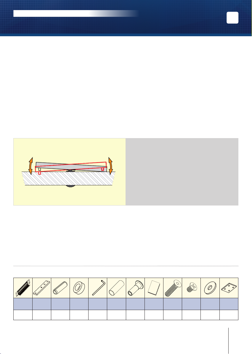
- The Armature plate must be able to pivot
slightly about its center mounting screw
to compensate for any door misalignment.
MAINTENANCE
The Electro magnet and armature plate have a specic treatment which strengthens the protection against
wear and corrosion. These products do not require high maintenance. Nevertheless to ensure optimum
performance, it is recommended to clean regularly the surfaces in contact of the electro magnet and armature
plate with a cloth and non abrasive products. If traces of corrosion appear, it is recommended to clean and
oil the contact surfaces. Check and tighten regularly all the xings of the Electro magnet and ensure that
while the armature is able to pivot on its mounting, the xing bolt is not liable to loosen (we recommend
thread-lock for all xing bolts).
3] PACKAGE CONTENTS
ELECTROMAGNETIC LOCK V1ER
Mortice
magnetic
Armature
lock
1 1 2 1 1 1 1 1 1 8 2 2
plate
Roll pin
5x16
Rubber
washer
10x6x4
Key
3mm
Guide
piece
Cap
nut
Installation
manual
M5x20
screw
M5x8
screw
Steel
washer
Joggle
bracket
3cdvigroup.com
Page 4
INSTALLATION MANUAL
V1ER - V3E - V3ER - V3E35R - V4E - V4ER - V5E
Mortice Electromagnetic locks
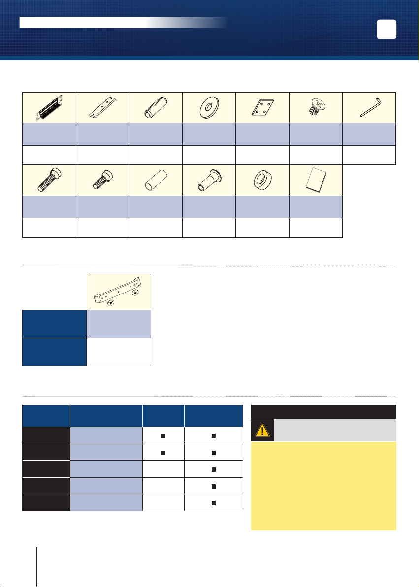
ELECTROMAGNETIC LOCK V3E - V3ER - V3E35R - V4E - V4ER - V5E
EN
Mortice
magnetic
lock
1 1 2 2 2 8 1
M8x35
screw
1 1 1 1 1 1
Armature
plate
M8x25
screw
Roll pin
5x16
Guide
piece
Steel
washer
Cap
nut
Joggle
bracket (excepted
for the V5E)
Rubber
washer
15x9x4
M5x8
screw
Installation
manual
4] OPTIONAL ACCESSORIES
References
Description
AMCCHANFR16
AMCCHANFR20
Armature
mounting plate
5] ELECTRICAL CONNECTIONS
TERMINAL
BLOCK
+ 12 or 24V dc
CORRESPONDENCE
V3E - V4E
V5E
V1ER - V3ER
V3E35R - V4ER
IMPORTANT NOTE
12V dc factory setup
Key
5mm
- - 0 V
N.C NC (Normally closed) -
COM COM -
N.O NO (Normally open) -
The NO/NC signal only switches when the door is closed
with the power to it on.
4 cdvigroup.com
Check the jumper position
before connecting
the lock to the
input current. A wrong position
could damage the lock. This
type of damage is not covered
by the warranty.
Page 5
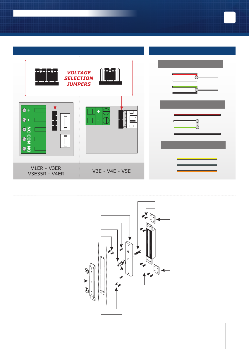
V1ER - V3ER
V3E35R - V4ER
V3E - V4E - V5E
VOLTAGE
SELECTION
JUMPERS
INSTALLATION MANUAL
V1ER - V3E - V3ER - V3E35R - V4E - V4ER - V5E
Mortice Electromagnetic locks
EN
WITH BUILT-IN PCB BOARD
12V dc 24V dc
6]
INSTALLATION (WITH AMCCHANFR20 OR AMCCHANFR16)
Armature plate
Roll pin
Steel washer
Screw
DIRECT CONNECTION
Red
White
Green
Black
Red
White
Green
Black
Yellow NC
Blue COM
Orange NO
Armature screw
Screw
Joggle bracket
12V DC
+
-
24V DC
+
-
CONTACT
Armature plate support
AMCCHANFR20 or
AMCCHANFR16
(Optional)
Joggle bracket
Screw
Screw
Rubber washer
5cdvigroup.com
Page 6
INSTALLATION MANUAL
V1ER - V3E - V3ER - V3E35R - V4E - V4ER - V5E
Mortice Electromagnetic locks
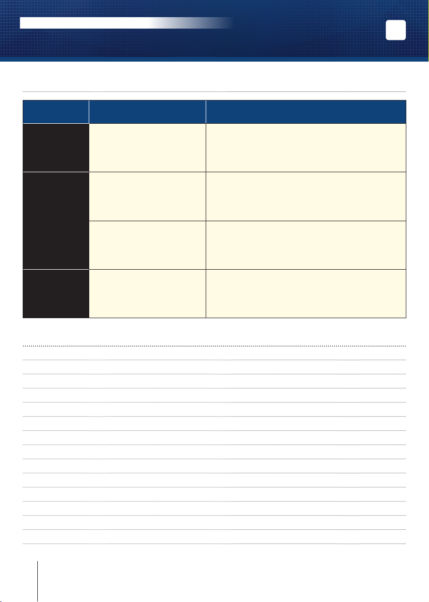
7] FAULT FINDING
PROBLEM POSSIBLE CAUSE SOLUTION
- Check that the wires are connected to the right
Door locking
impossible
Holding force
reduced
The lock is not receiving
DC current.
The lock and the armature are not
lined up with each other.
Low voltage or armature jammed.
terminals.
- Check that the power supply is compatible.
- Check that the lock is connected to the circuit
correctly.
- Check that the lock is connected to the circuit
correctly.
- Check that the electromagnet and the armature
are properly aligned.
- Check that the contact faces are free from dirt and rust.
- Check that the armature is soft mounted.
- Check that the lock is receiving the correct power
supply satisfactorily.
- check the tightening of the armature
and the condition of the rubber.
EN
Faulty reed
switch
8] NOTES
Voltage too low. Misalignment.
- Check the power supply.
- Cable cross section to be determined according
to the power supply and the locking.
- e.g.: 2 x 1.5mm2 ≥ 10m.
6 cdvigroup.com
Page 7

MANUEL D’INSTALLATION
V1ER - V3E - V3ER - V3E35R - V4E - V4ER - V5E
Ventouse électromagnétiques encastrées
FR
7cdvigroup.com
Page 8

Extranet : EXE-CDVI_IM MORTICE MAGLOCKS CMYK A5 EN 01
*G0301EN0458V01*
CDVI Group
FRANCE (Headquarter/Siège social)
Phone: +33 (0)1 48 91 01 02
Fax: +33 (0)1 48 91 21 21
Reference : G0301EN0458V01
CDVI
FRANCE + EXPORT
Phone: +33 (0)1 48 91 01 02
Fax: +33 (0)1 48 91 21 21
CDVI AMERICAS
[CANADA - USA]
Phone: +1 (450) 682 7945
Fax: +1 (450) 682 9590
CDVI
BENELUX
[BELGIUM - NETHERLAND - LUXEMBOURG]
Phone: +32 (0) 56 73 93 00
Fax: +32 (0) 56 73 93 05
CDVI
TAIWAN
Phone: +886 (0)42471 2188
Fax: +886 (0)42471 2131
CDVI
SUISSE
Phone: +41 (0)21 882 18 41
Fax: +41 (0)21 882 18 42
CDVI
CHINA
Phone: +86 (0)10 62414516
Fax: +86 (0)10 62414519
CDVI
IBÉRICA
[SPAIN - PORTUGAL]
Phone: +34 (0)935 390 966
Fax: +34 (0)935 390 970
CDVI
ITALIA
Phone: +39 0321 90 573
Fax: +39 335 127 89 96
CDVI
MAROC
Phone: +212 (0)5 22 48 09 40
Fax: +212 (0)5 22 48 34 69
CDVI
SWEDEN
[SWEDEN - DENMARK - NORWAY - FINLAND]
Phone: +46 (0)31 760 19 30
Fax: +46 (0)31 748 09 30
CDVI
UK
[UNITED KINGDOM - IRELAND]
Phone: +44 (0)1628 531300
Fax: +44 (0)1628 531003
CDVI DIGIT
FRANCE
Phone: +33 (0)1 41 71 06 85
Fax: +33 (0)1 41 71 06 86
All the information contained within this document (pictures, drawing, features, specications and dimensions)
could be perceptibly different and can be changed without prior notice.
The installer’s choice
cdvigroup.com
 Loading...