

Page 1
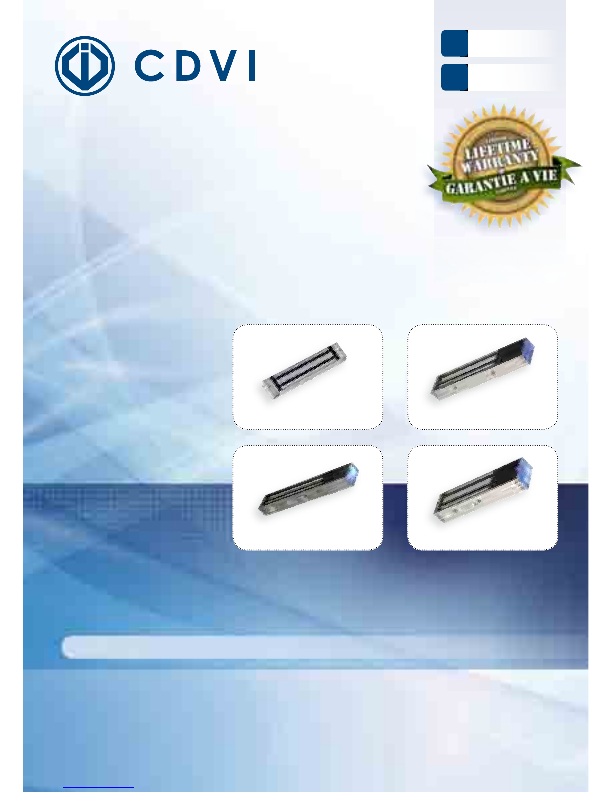
V1SR
V3S
V3SR
V3SRB
V4S
V4SR
V4SRB
V5S
V5SR
V5SRB
V3S - V3SR - V3SRB
V1SR
V4S - V4SR - V4SRB
V5SRB
V5S - V5SR - V5SRB
FR
EN
FRANCAIS
ENGLISH
INSTALLATION MANUAL
Range: Locking Devices /
Surface Mount Electromagnetic locks
* Refer to limited lifetime warranty conditions. / Voir conditions de garantie à vie limitée.
MANUEL D’INSTALLATION
Gamme: Verrouillage
Ventouses électromagnétiques appliques
Page 2
EN
V1SR - V3S - V3SR - V3SRB - V4S - V4SR - V4SRB - V5S - V5SR - V5SRB
Surface mount Electromagnetic locks
INSTALLATION MANUAL
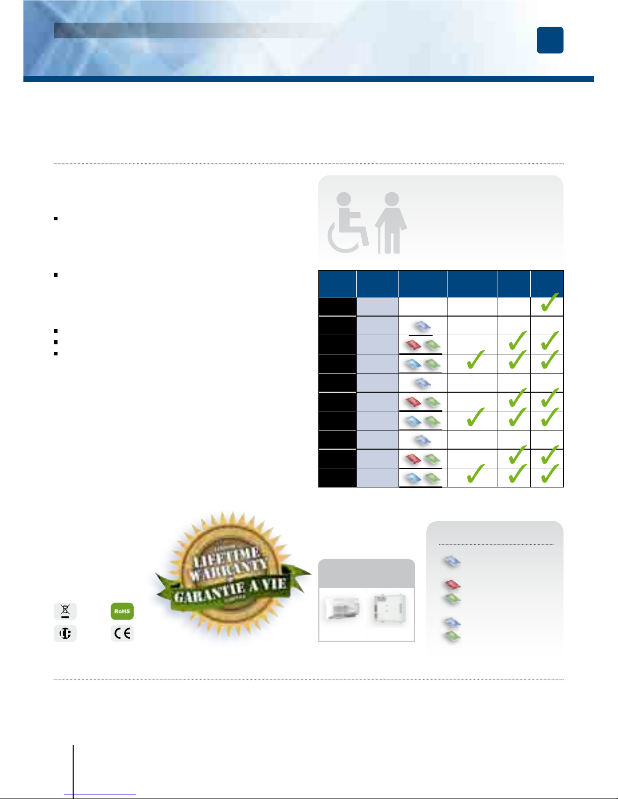
1] PRODUCT PRESENTATION
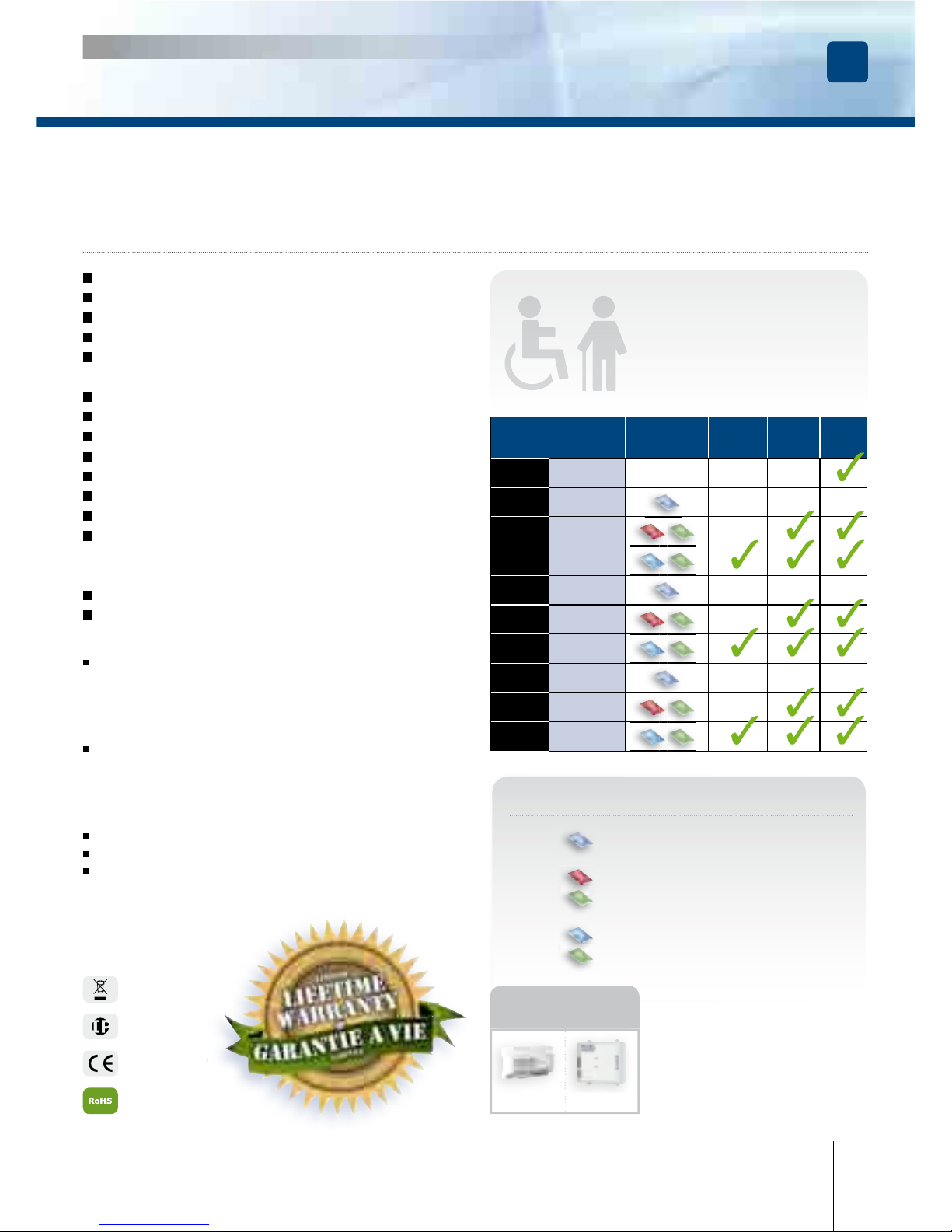
The V3S, V4S and V5S series
with signalling are suitable for
the new regulations covering
assistance to persons with
reduced mobility.
Thank you for buying our products and for the confi dence you placed
in our company.
180, 300, 400 or 500kg**.
Electronic protection
to eliminate back EMF.
Electromagnetic lock dimensions (L x W x D):
- V1SR = 167 x 34 x 21mm.
- V3S series = 248 x 45 x 26mm,
- V4S series = 255 x 50 x 27mm,
- V5S series = 266 x 66 x 40mm.
Armature dimensions (l x w x d):
- 180kg = 130 x 32 x 9mm,
- 300kg = 185 x 38 x 11mm,
- 400kg= 185 x 45 x 12mm,
- 500kg = 185 x 60 x 12mm.
Silent operation.
Power supply: 12/24V dc.
Power absorption:
- 12 V DC = 550mA,
- 24 V DC = 275mA.
Refs
Holding
force
Visual
feedback
Audible
feedback
Relay
Monitored
V1SR 180 kg
-
- -
V3S 300kg
- - -
V3SR 300kg
-
V3SRB 300kg
V4S 400kg - - -
V4SR 400kg
-
V4SRB 400kg
V5S 500kg - - -
V5SR 500kg
-
V5SRB 500kg
EC certifi cation
WEEE
IP42
cdvi.com
cdvigroup.com
COLOUR CODES
BLUE ACTIVE VOLTAGE
RED LOCKED
GREEN OPEN
BLUE LOCKED
GREEN OPEN + BUZZER
RoHS
ARD212 BS60
Recommended
power supplies
* Refer to limited lifetime warranty conditions.
** Depending on the version.
2] REMINDERS AND RECOMMENDATIONS
The function of an electromagnetic lock is to ensure the locking of an access point. This document is a guide
of installation which will allow you to secure the installation according to the characteristics of the product,
the site and the environmental requirements.
Page 3

EN
V1SR - V3S - V3SR - V3SRB - V4S - V4SR - V4SRB - V5S - V5SR - V5SRB
Surface mount Electromagnetic locks
INSTALLATION MANUAL
3
cdvi.com
cdvigroup.com
POWER SUPPLY
An electromagnetic lock always operates in DC current, a very low safety voltage. The Diax
®
electromagnetic
lock is recommended for use with power supplies manufactured by CDVI, however, other power supplies
may be used on condition that they are of equivalent quality and characteristics recti ed, ltered, regulated
and protected by fuse in primary and secondary sectors.
MOUNTING RECOMMENDATIONS
- De ne the level of security of the access.
- Determine the maximum strength of holding force to this level of security.
- Select the Diax
®
electromagnetic lock according to the environment, the inside, the outside, the climatic
constraints, (For example: stainless steel dedicated to an outside use).
- Always install the electromagnetic lock on the secure side of the place to be secured.
- Indeed make sure that the frame and opening, receiving or supporting the electromagnetic lock, armature
plate and their accessories, are solid and resistant to damage or wear over a period of time.
- Consider any bracketry required for the assembly according to the type of support receiving
the electromagnetic lock and armature plate.
- De ne the passage of cables to ensure the protection against the vandalism and the environmental
requirements (in particular through fl exible hoses of door, glands, gutters, cross cables, plastic tubes).
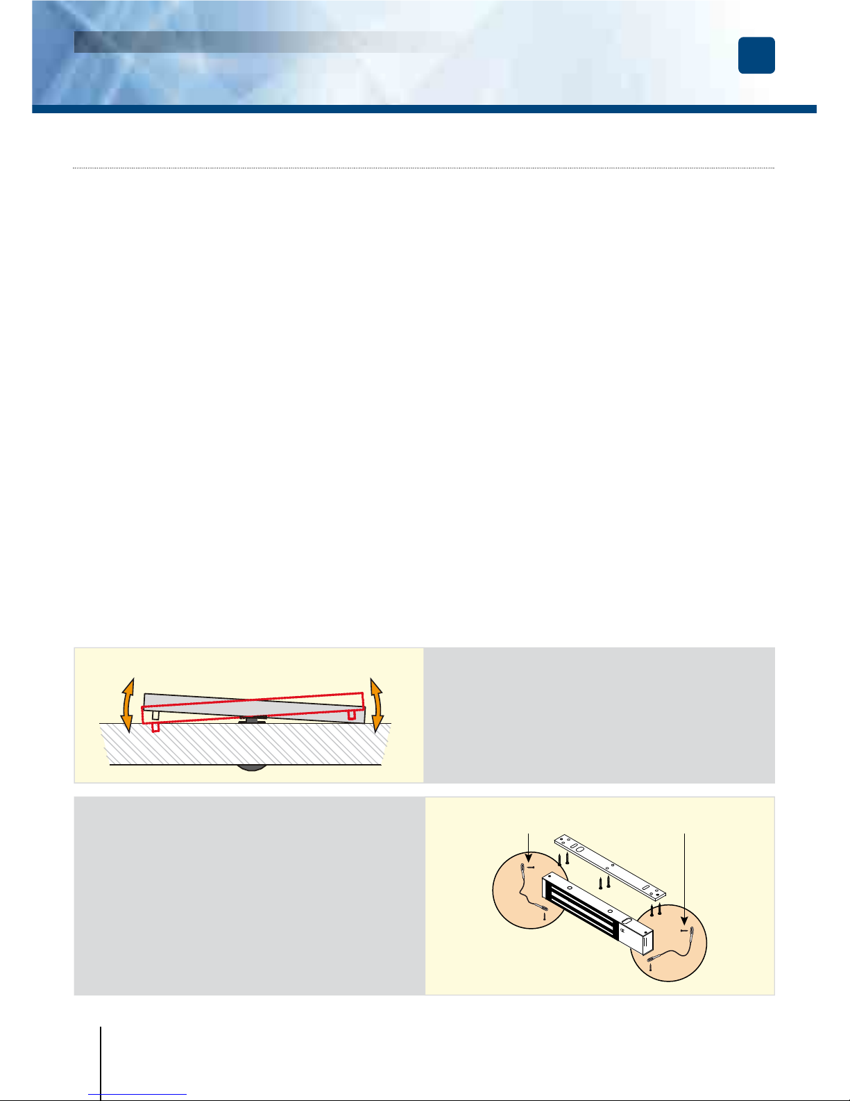
Security ropes
The electromagnetic lock undergoes repeated
shocks and the vibration at the points of fi xation
on the frame (frequencies of openings / closures,
attempt of opening wears closed and attempts
of vandalism) which can loosen the fi xing bolts/
screws. To prevent the risk of the electromagnetic
block from falling, install both security ropes
supplied, to guarantee the safety of the users
(see attached plan).
Security rope
( xing on the magnetic lock and the frame)
APPROVAL RELATIVE TO EMERGENCY EXITS:
In the case of an installation of electromagnetic lock on emergency exits, it is imperative to make sure that
these exit points will be automatically free in case of re alarm, to open in the event of a re alarm to allow
evacuation of the premises. The electromagnetic lock installed on emergency exits must be in accordance
with the re approval department (Ex: In France = NF 61-937).
For more information, contact CDVI, the local fi re offi cer or the safety offi cer responsible for the building.
Armature plate
- It is vital to fi x the electromagnetic lock
and armature plate solidly on their supports.
- Make sure that the magnet and the armature
meet evenly over their entire mating surfaces.
- The Armature plate must be able to pivot
slightly about its center mounting screw
to compensate for any door misalignment.
Page 4

EN
V1SR - V3S - V3SR - V3SRB - V4S - V4SR - V4SRB - V5S - V5SR - V5SRB
Surface mount Electromagnetic locks
INSTALLATION MANUAL
4
cdvi.com
cdvigroup.com
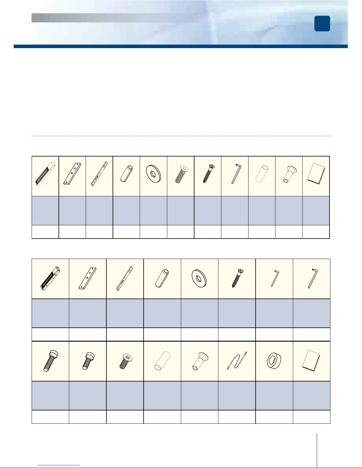
3] PACKAGE CONTENTS
Surface
mount
magnetic
lock
Armature
plate
Fixing
plate
Roll pin
5x16
Steel
washer
4x25
wood
screw
Key
3mm
Key
5mm
1 1 1 2 2 7 1 1
M8x35
screw
M8x25
screw
3x8
self-tapping
screw
Guide
piece
Cap
nut
Safety
rope
Rubber
washer
Installation
manual
1 1 1 1 1 2 1 1
Surface
mount
magnetic
lock
Armature
plate
Fixing
plate
Roll pin
5x16
Steel
washer
3x25
wood
screw
Key
3mm
Guide
piece
Cap
nut
Installation
manual
M5x20
screw
1 1 1 2 2 5 1 1 1 1 1
ELECTROMAGNETIC LOCK V1SR
ELECTROMAGNETIC LOCK V3S - V3SR - V3SRB - V4S - V4SR - V4SRB - V5S - V5SR - V5SRB
MAINTENANCE
The Electro magnet and armature plate have a speci c treatment which strengthens the protection against wear
and corrosion. These products do not require high maintenance. Nevertheless to ensure optimum performance,
it is recommended to clean regularly the surfaces in contact of the electro magnet and armature plate with a cloth
and non abrasive products. If traces of corrosion appear, it is recommended to clean and oil the contact surfaces.
Check and tighten regularly all the xings of the Electro magnet and ensure that while the armature is able to pivot
on its mounting, the xing bolt is not liable to loosen (we recommend thread-lock for all xing bolts).
Page 5

EN
V1SR - V3S - V3SR - V3SRB - V4S - V4SR - V4SRB - V5S - V5SR - V5SRB
Surface mount Electromagnetic locks
INSTALLATION MANUAL
5] ELECTRICAL CONNECTIONS
The NO/NC signal only switches when the door is closed with the power to it on.
TERMINAL
BLOCK
CORRESPONDENCE
V3S
V4S - V5S
V3SR - V3SRB - V4SR
V4SRB - V5SR - V5SRB
+ 12 or 24V dc
- - 0 V
N.C NC (Normally closed) -
COM COM -
N.O NO (Normally open) -
WITH BUILT-IN PCB BOARD
12V dc
Factory
Setup
12V dc 12V dc24V dc 24V dc 24V dc
5
cdvi.com
cdvigroup.com
4] OPTIONAL ACCESSORIES
References
L3L4L5 Z3Z4Z5 UBKU UBKP AMA3AMA5
DPM300
DPM500
LZ1
Description
L-shaped bracket
for lock
Z-shaped bracket
for lock
Armature base
for glass door
Universal base
for glass door
Armature base
Door position
monitoring
L & Z-shaped
bracket
for 180kg lock
V3S - V4S - V5S V3SR - V4SR - V5SR
V3SRB - V4SRB - V5SRB
-+
Page 6

EN
V1SR - V3S - V3SR - V3SRB - V4S - V4SR - V4SRB - V5S - V5SR - V5SRB
Surface mount Electromagnetic locks
INSTALLATION MANUAL
6
cdvi.com
cdvigroup.com
6]
INSTALLATION (EXAMPLE: V3S SERIES)
DIRECT CONNECTION
12V DC 24V DC CONTACT
Red
Red
Yellow NC
Blue COM
Orange NO
+
+
White
White
-
-
Green
Green
Black Black
xing plate
Security
rope
Security
rope
Armature plate
M8
screw
Cap nut
Guide piece
Rubber washer
Roll pin
Steel washer
Rubber washer
Fixing plate
Door frame
Outwards opening
door (push door).
Electromagnetic
lock
Armature
plate
Cap nut
Guide piece
M8 screw
Door
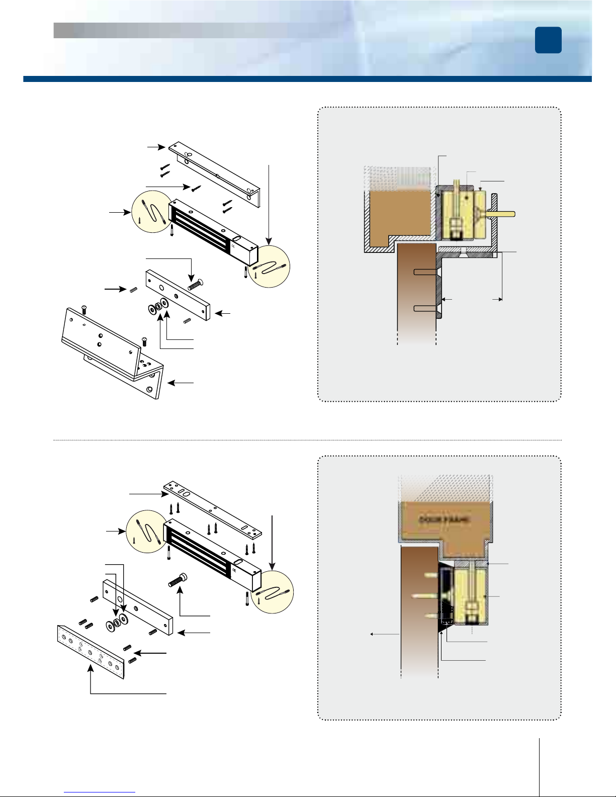
Installation on an outward opening
door (Push door)
Check the jumper position before connecting the lock to the input current.
A wrong position could damage the lock. This type of damage is not covered
by the warranty.
IMPORTANT NOTE
Page 7
EN
V1SR - V3S - V3SR - V3SRB - V4S - V4SR - V4SRB - V5S - V5SR - V5SRB
Surface mount Electromagnetic locks
INSTALLATION MANUAL
Electromagnetic lock
Armature plate
Adjustable
Inward opening door (Pull door)
(installed with “Z” and “L” brackets)
Z shaped bracket
:
Z3Z4Z5
L shaped bracket
:
- L3L4 (300 - 400 Kg),
- L5 (500kg).
L shaped bracket
Z shaped
bracket
Installation on an inward opening
door (Pull door)
Fixing screw
Rubber washer
Roll pin
Steel washer
Armature plate
M8 screw
DOOR FRAME
DOOR
7] INSTALLATION WITH ACCESSORIES
Fixing plate
Security
rope
Security
rope
Security
rope
Security
rope
Armature housing
Armature plate
Rubber washer
Roll pin
Steel washer
Armature
screw
Outwards opening door (push door).
(installed with armature housing)
Installation with an Armature
housing
Armature housing
AMA3 or AMA5
DOOR FRAME
Electromagnetic
lock
DOOR
EXT.
opening
7
cdvi.com
cdvigroup.com
Page 8
EN
V1SR - V3S - V3SR - V3SRB - V4S - V4SR - V4SRB - V5S - V5SR - V5SRB
Surface mount Electromagnetic locks
INSTALLATION MANUAL
8
cdvi.com
cdvigroup.com
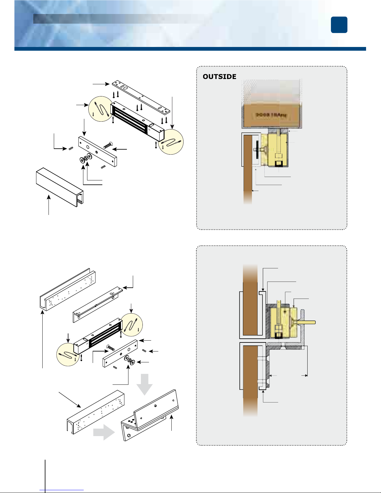
Fixing plate
Security
rope
Security
rope
Armature housing for glass door
UBKU
Rubber washer
Roll pin
Steel washer
Armature
screw
Outward opening door (Push door)
(installed with UBKU brackets)
Installation with base for glass door
DOOR FRAME
Electromagnetic lock
Universal base for glass
door UBKU
DOOR
Fixing plate
Armature
plate
DOOR
GLASS
FRAME
Adjustable
UBKP
Inward opening door (Pull door)
(installed with “UBKP”, “L3L4L5”
and Z3Z4Z5 brackets)
Installation with base
for glass door
Universal
housing for
glass door
UBKP
Rubber washer
Steel washer
Armature
plate
Armature
screw
Security
rope
Security
rope
Roll pin
Z shaped bracket
Z3Z4Z5
L shaped bracket
:
- L3L4 (300 - 400 Kg),
- L5 (500kg).
Page 9
FR
V1SR - V3S - V3SR - V3SRB - V4S - V4SR - V4SRB - V5S - V5SR - V5SRB
Ventouses électromagnétiques appliques
MANUEL D’INSTALLATION
8] FAULT FINDING
Installation with DPM300 - DPM400 - DPM500 (Door position monitoring)*
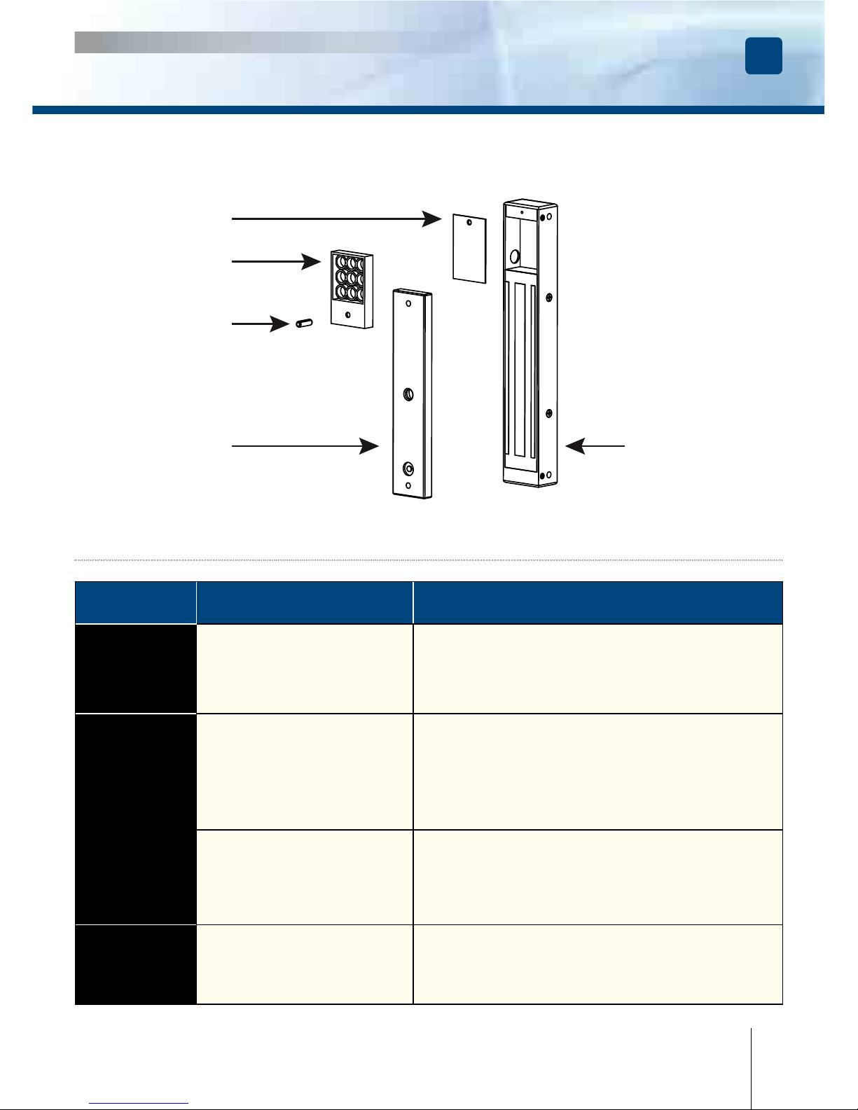
Roll pin
Armature plate
Electromagnetic lock
DPM300
Fixed on the armature
DPM300
Fixed on the
electromagnetic lock
PROBLEM POSSIBLE CAUSE SOLUTION
Door
locking
impossible
The lock is not receiving
DC current.
- Check that the wires are connected to the right
terminals.
- Check that the power supply is compatible.
- Check that the lock is connected to the circuit
correctly.
Holding
force
reduced
The lock and the armature are
not lined up with each other.
- Check that the lock is connected to the circuit
correctly.
- Check that the electromagnet and the armature
are properly aligned.
- Check that the contact faces are free from dirt and rust.
- Check that the armature is soft mounted.
Low voltage or armature
jammed.
- Check that the lock is receiving the correct power
supply satisfactorily.
- check the tightening of the armature
and the condition of the rubber.
Faulty
reed
switch
Voltage too low. Misalignment.
- Check the power supply.
- Cable cross section to be determined according
to the power supply and the locking.
- e.g.: 2 x 1.5mm2 ≥ 10m.
9
cdvi.com
cdvigroup.com
* Optional. Sold separately.
Page 10

EN
9] LIMITED LIFETIME WARRANTY [EXTRACT]*
CDVI warrants this product to be free from defects in material and workmanship, when it has been installed
in accordance with the manufacturer’s instructions and has not been modi ed or tampered with. Only product
recognized by CDVI to be defective should be returned under these warranty terms if accompanied
by an RMA (Return Material Authorization Number) provided by CDVI. CDVI, at its option, shall repair
or replace the defective product at CDVI premises or at any CDVI approved service center. This warranty
does not cover any damage due to accident, misuse, abuse or negligence. This warranty is valid only
if the product is registered, within 1 month from delivery to the nal costumer. To obtain full details of this
warranty and to register the product to commence the “Limited Lifetime Warranty”, complete the enclosed
registration card and return it, either by e-mail or post, to the relevant CDVI address or completion of the
on line registration at www.cdvigroup.com. Repair or replacement of the defective product is the exclusive
remedy. CDVI shall not be liable for any incidental or consequential damages arising from any defect in, or
malfunction of, its product. In no event the entire liability can not exceed the purchase price of the product.
The CDVI local country contact details can be found on line by visiting www.cdvigroup.com or on the back
cover of the installation manual.
DISCLAIMER OF WARRANTY: EXCEPT AS STATED ABOVE, CDVI MAKES NO WARRANTIES, EITHER
EXPRESS OR IMPLIED, AS TO ANY MATTER WHATSOEVER, INCLUDING THE CONDITION OF ITS PRODUCTS,
THE TRANSPORTATION, THEIR MERCHANTABILITY OR FITNESS FOR ANY PARTICULAR PURPOSE.
10] NOTES
* Refer to complete limited lifetime warranty on cdvigroup website.
INSTALLATION MANUAL
V1SR - V3S - V3SR - V3SRB - V4S - V4SR - V4SRB - V5S - V5SR - V5SRB
Surface mount Electromagnetic locks
10
cdvi.com
cdvigroup.com
Page 11
FR
1] PRESENTATION PRODUIT
Merci pour l’achat de ce produit et pour la confi ance que vous accordez
à notre entreprise.
Applique**.
1 relais**.
Signal**.
Signalisation lumineuse et sonore**.
Force de rétention : 180, 300, 400
ou 500 kg**.
NFS 61-937.
Filin de sécurité*.
Haute résistance à la corrosion.
Livrée avec contre-plaque.
Pas d’usure mécanique.
Facilité d’installation.
Installation en intérieur.
Sécurité positive
(libère instantanément l’accès
en cas de coupure de courant).
Pas de magnétisme résiduel.
Varistance incorporée : Protection
électronique intégrée contre l’effet de self.
Dimensions des ventouses (L x l x P) :
- V1SR = 167 x 34 x 21 mm,
- Gamme V3S = 248 x 45 x 26 mm,
- Gamme V4S = 255 x 50 x 27 mm,
- Gamme V5S = 266 x 66 x 40 mm.
Dimensions des contre-plaques (L x l x P) :
- 180 kg = 130 x 32 x 9 mm,
- 300 kg = 185 x 38 x 11 mm,
- 400 kg = 185 x 45 x 12 mm,
- 500 kg = 185 x 60 x 12 mm.
Fonctionnement silencieux.
Alimentation : 12/24 V DC.
Consommation :
- 12 V DC = 550 mA,
- 24 V DC = 275 mA.
Refs
Force de
rétention
Leds
Buzzer Relais Signal
V1SR 180 kg
-
- -
V3S 300 kg
- - -
V3SR 300 kg
-
V3SRB 300 kg
V4S 400 kg - - -
V4SR 400 kg
-
V4SRB 400 kg
V5S 500 kg - - -
V5SR 500 kg
-
V5SRB 500 kg
Certifi cation CE
DEEE
IP42
CODES COULEURS
BLEU
TENSION ACTIVE
ROUGE
VERROUILLÉ
VERT
OUVERT
BLEU
VERROUILLÉ
VERT
OUVERT + BUZZER
RoHS
ARD212 BS60
Alimentations
préconisées
V1SR - V3S - V3SR - V3SRB - V4S - V4SR - V4SRB - V5S - V5SR - V5SRB
Ventouses électromagnétiques appliques
MANUEL D’INSTALLATION
cdvi.com
cdvigroup.com
Page 12
FR
2] RAPPELS ET RECOMMANDATIONS
ALIMENTATION
Une ventouse électromagnétique fonctionne toujours en courant continu, impérativement en très basse
tension de sécurité (TBTS). Les ventouses électromagnétiques Diax® sont préconisées avec les alimentations
de la gamme CDVI, toutefois, d’autres alimentations peuvent être utilisées à la condition que celles-ci
présentent une qualité et des caractéristiques équivalentes, notamment redressée, ltrée, régulée, protégé
par fusible en primaire et secondaire…
CONSEIL D’INSTALLATION
- Dé nir le niveau de sécurité de l’accès.
- Adapter la force de rétention maximum à ce niveau de sécurité.
- Sélectionner la ventouse électromagnétique Diax
®
en fonction de l’environnement, intérieur, extérieur,
contraintes climatiques, … (Par exemple : inox dédiée à une utilisation extérieure).
- Installer toujours la ventouse à l’intérieur du lieu à sécuriser.
- Bien s’assurer que le dormant et l’ouvrant, recevant ou supportant la ventouse, la contre-plaque
et leurs accessoires, soient solides et résistants dans le temps.
- Adapter les éléments de montage en fonction du type support recevant la ventouse et la contreplaque
(visserie, chevilles, accessoires,…).
- Dé nir le passage des câbles pour en assurer la protection contre le vandalisme et les contraintes
environnementales (notamment par l’intermédiaire de fl exibles de porte, presse-étoupe, goulottes,
passe câbles, tubes plastiques, …).
Les fi lins de sécurités
La ventouse électromagnétique subit tout au long
de sa vie une accumulation de chocs répétés
et de sollicitations aux niveaux des points de fi xation
sur le dormant, fréquences d’ouvertures/fermetures,
(tentative d’ouverture porte verrouillée et tentatives
de vandalisme) ce qui peut générer sa désolidarisation
du support au moment de l’ouverture. Afi n de pallier
au risque de chute du bloc ventouse, installer les deux
fi lins de sécurité fournis pour garantir la sécurité des
utilisateurs (voir schéma).
La contre-plaque
Filin de sécurité
( xations sur ventouse et bati)
Filin de sécurité
( xations sur ventouse et bati)
La fonction d’une ventouse électromagnétique est d’assurer le verrouillage d’un accès. Ce document
est un guide de pose qui vous permettra de sécuriser l’installation en fonction des caractéristiques du produit,
du site et des contraintes environnementales.
NORME INCENDIE RELATIVE AUX ISSUES DE SECOURS
Dans le cas d’une installation de ventouses électromagnétiques sur des issues de secours, il est impératif
de s’assurer que ces accès seront automatiquement libres en cas d’alarme incendie, pour permettre
une évacuation des lieux. Les ventouses électromagnétiques installées sur des issues de secours doivent
impérativement être conforme à la norme incendie locale (Ex : En France = NFS 61-937).
Pour plus d’informations, rapprochez-vous de CDVI, de l’organisme certifi é local ou du centre de sécurité du bâtiment.
V1SR - V3S - V3SR - V3SRB - V4S - V4SR - V4SRB - V5S - V5SR - V5SRB
Ventouses électromagnétiques appliques
MANUEL D’INSTALLATION
cdvi.com
cdvigroup.com
Page 13
FR
3] ÉLÉMENTS INCLUS
Ventouse
saillie
Contre-
plaque
Plaque
de
montage
Goupille
5x16
Rondelle
acier
Vis bois
4x25
clef
3 mm
clef
5 mm
1 1 1 2 2 7 1 1
Vis
M8x35
Vis
M8x25
Vis
autoforeuse
3x8
Embout
de
guidage
Ecrou
borgne
Filin
de
sécurité
Rondelle
caouchouc
Notice
1 1 1 1 1 2 1 1
Ventouse
saillie
Contre-
plaque
Plaque
de
montage
Goupille
5x16
Rondelle
acier
Vis
M5x20
Vis bois
3x25
Clef
3 mm
Embout
de
guidage
Ecrou
borgne
Notice
1 1 1 2 2 1 5 1 1 1 1
VENTOUSES V1SR
VENTOUSES V3S - V3SR - V3SRB - V4S - V4SR - V4SRB - V5S - V5SR - V5SRB
ENTRETIEN
La ventouse et sa contreplaque disposent d’un revêtement spéci que qui renforce la protection contre l’usure
et la corrosion. Ces produits nécessitent donc peu d’entretien. Néanmoins pour assurer une fonctionnalité
optimum, Il est recommandé de nettoyer régulièrement les surfaces en contact de la ventouse
et de sa contreplaque avec un chiffon et produits non abrasifs. Si des traces de corrosion venaient à apparaître,
il est recommandé de nettoyer et huiler légèrement ces mêmes surfaces en contact. Véri er et resserrer
régulièrement l’ensemble des xations de la ventouse. Il est nécessaire de mettre un frein- let sur la vis
pivot de la contreplaque.
V1SR - V3S - V3SR - V3SRB - V4S - V4SR - V4SRB - V5S - V5SR - V5SRB
Ventouses électromagnétiques appliques
MANUEL D’INSTALLATION
13
cdvi.com
cdvigroup.com
Page 14
FR
Filet de
sécurité
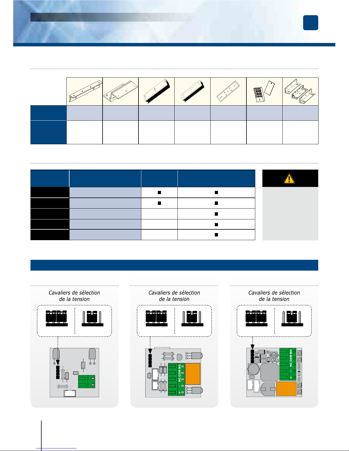
5] RACCORDEMENT
Le signal NO/NC ne commute que lorsque la porte fermée et sous tension.
BORNIER CORRESPONDANCE
V3S
V4S - V5S
V3SR - V3SRB - V4SR
V4SRB - V5SR - V5SRB
+
12 or 24 V DC
-
- 0 V
N.C
NC (Normalement fermé)
-
COM
COM
-
N.O
NO (Normalement ouvert)
-
AVEC ÉLECTRONIQUE DÉPORTÉE
12 V DC
Réglage
usine
12 V DC 12 V DC 12 V DC24 V DC 24 V DC 24 V DC
4] ACCESSOIRES EN OPTION
Références
L3L4 (300KG)
L5 (500KG)
Z3Z4Z5 UBKU UBKP
AMA3 (300KG)
AMA5 (500KG)
DPM300
DPM500
LZ1
Description
Support en “L”
pour ventouse
(300,400 & 500kg)
Support en “Z”
pour ventouse
(300,400 & 500kg)
Support
de contre-plaque
pour porte en verre
(300,400 & 500kg)
Support universel
pour porte
en verre
(300,400 & 500kg)
Support
de contre-plaque
(300 & 500kg)
Contact
de position
de porte
(300 & 500kg)
Kit L & Z
Pour V1SR
(180 kg)
V3S - V4S - V5S V3SR - V4SR - V5SR
V3SRB - V4SRB - V5SRB
-+
V1SR - V3S - V3SR - V3SRB - V4S - V4SR - V4SRB - V5S - V5SR - V5SRB
Ventouses électromagnétiques appliques
MANUEL D’INSTALLATION
14
cdvi.com
cdvigroup.com
Page 15
FR
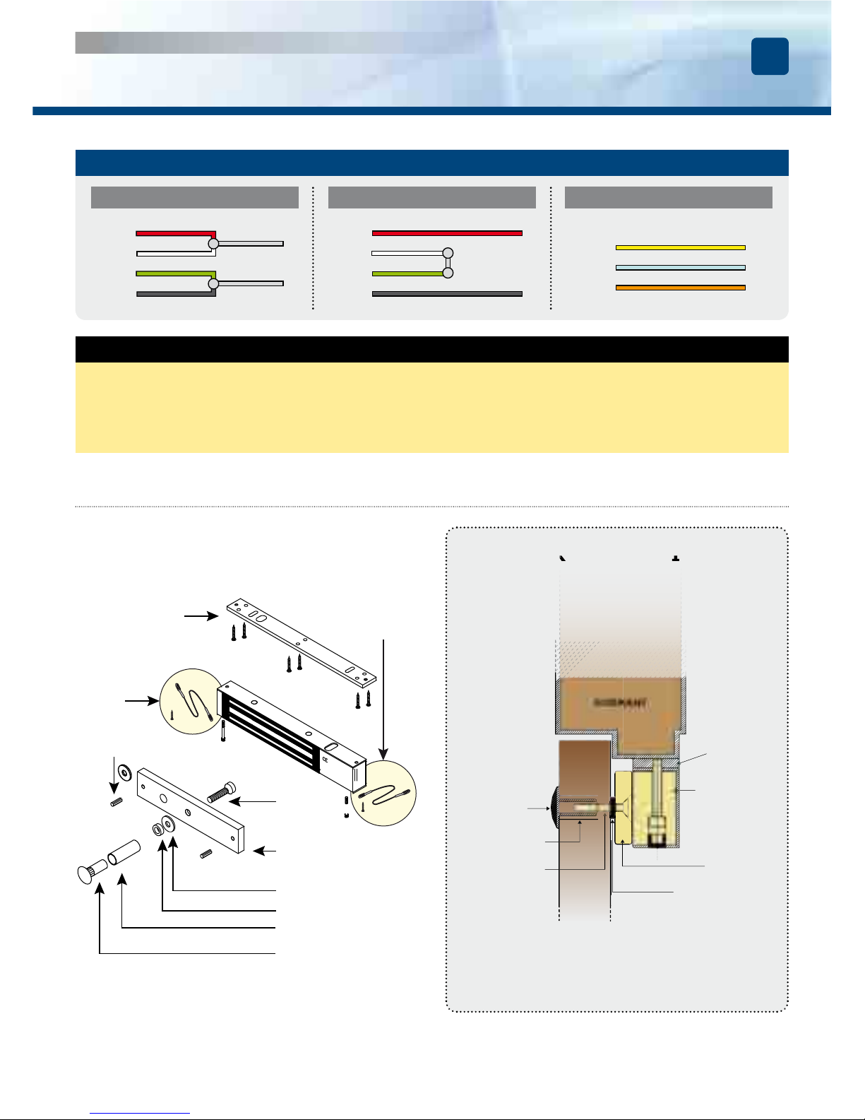
Vérifi er la position du cavalier avant de brancher la ventouse au courant d’entrée.
Une position incorrecte peut endommager la ventouse. Ce type de dommage
n’est pas couvert par la garantie.
NOTE IMPORTANTE
6]
MONTAGE (EXEMPLE: GAMME V3S)
CONNEXION DIRECTE
12 V DC 24 V DC CONTACT
Rouge
Rouge
Jaune NC
Bleu COM
Orange NO
+
Blanc
Blanc
-
-
Vert
Vert
Noir
Plaque de
montage
Filet de
sécurité
Filet de
sécurité
Contre-plaque
Écrou borgne
Embout de guidage
Rondelle caouchouc
Goupille
Rondelle acier
Rondelle
en caoutchouc
Plaque
de montage
DORMANT
porte à ouverture
extérieure
(Poussante)
Ventouse
Contre-plaque
Écrou borgne
Embout
de guidage
Vis M8
OUVRANT
Montage sur porte à ouverture
extérieure
(Poussante)
V1SR - V3S - V3SR - V3SRB - V4S - V4SR - V4SRB - V5S - V5SR - V5SRB
Ventouses électromagnétiques appliques
MANUEL D’INSTALLATION
cdvi.com
cdvigroup.com
Page 16
FR
V1SR - V3S - V3SR - V3SRB - V4S - V4SR - V4SRB - V5S - V5SR - V5SRB
Ventouses électromagnétiques appliques
MANUEL D’INSTALLATION
16
cdvi.com
cdvigroup.com
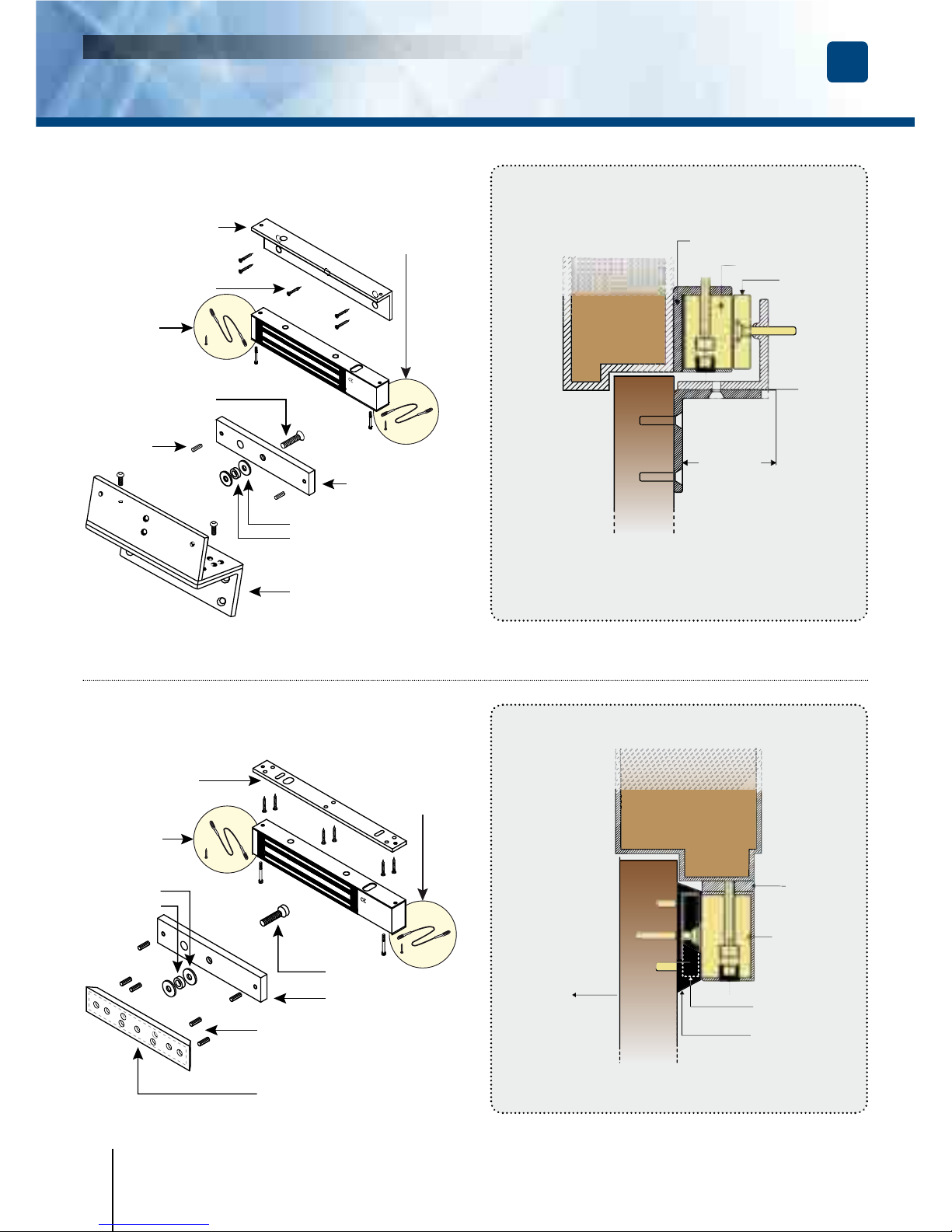
Filet de
sécurité
Filet de
sécurité
Filet de
sécurité
Filet de
sécurité
Ventouse
Contre-plaque
Réglable
Porte à ouverture
vers l’intérieur (Tirante)
(installé avec support “L” et “Z”).
Equerre en “Z”
Z3Z4Z5
Equerre en “L”
- L3L4 (300 - 400 Kg),
- L5 (500 kg).
Equerre en “L”
Equerre
en “Z”
Montage sur
porte à ouverture
intérieure (Tirante)
Vis de xation
Rondelle caouchouc
Goupille
Rondelle acier
Contre-plaque
Vis M8
DORMANT
OUVRANT
7] MONTAGE AVEC ACCESSOIRES
(EXEMPLE : GAMME V3S)
Plaque de
montage
Support de
contre-plaque
AMA3 - AMA5
Contre-plaque
Rondelle
caoutchouc
Goupilles
Rondelle
en acier
Vis
contre-plaque
Porte à ouverture vers l’extérieur
(poussante)
Montage avec support
de contre-plaque
Support
de contre-plaque
AMA3 or AMA5
Plaque de
montage
DORMANT
Ventouse
Contre-plaque
OUVRANT
Ouverture
extérieure
Page 17
FR
V1SR - V3S - V3SR - V3SRB - V4S - V4SR - V4SRB - V5S - V5SR - V5SRB
Ventouses électromagnétiques appliques
MANUEL D’INSTALLATION
17
cdvi.com
cdvigroup.com
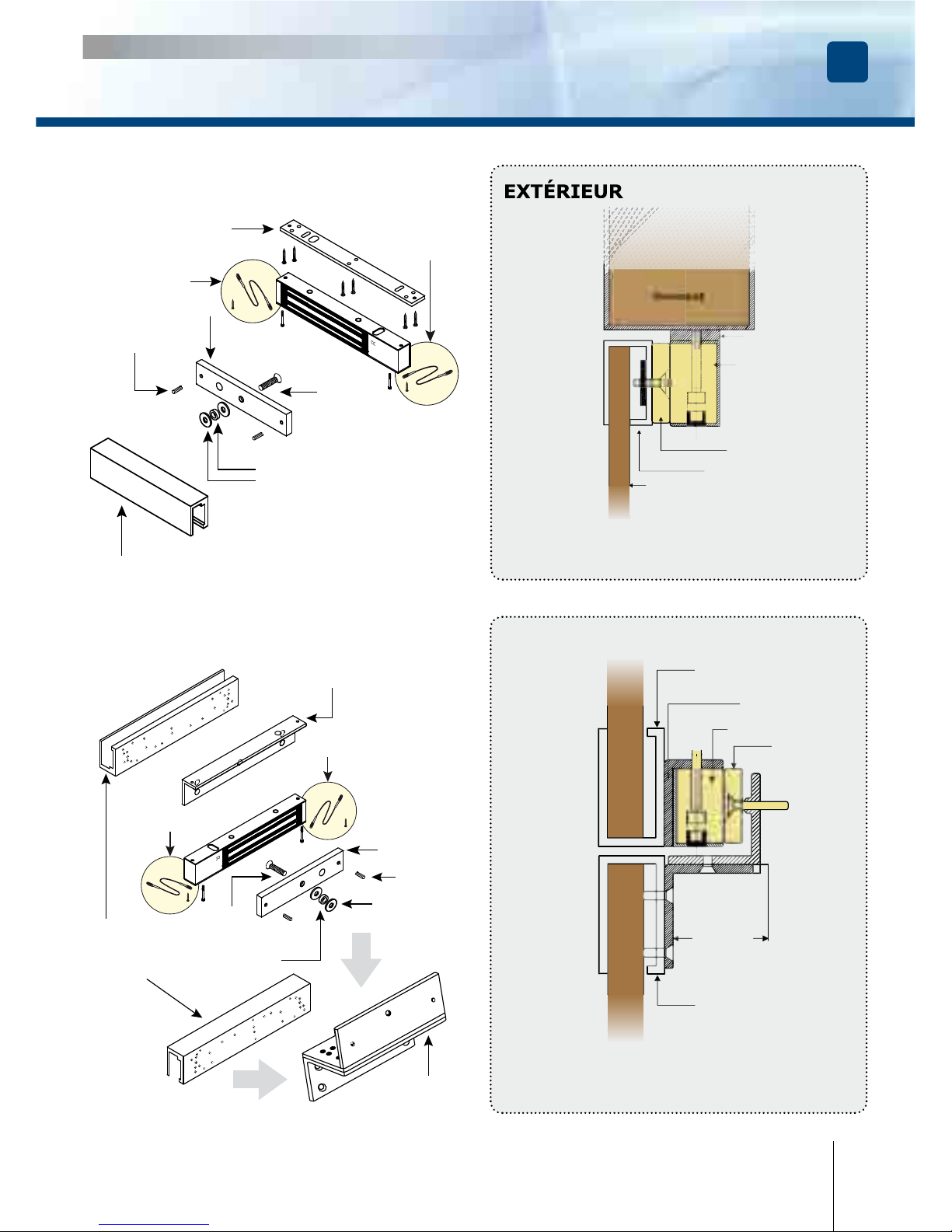
Plaque de montage
Contre-plaque
Support de contre-plaque
pour porte en verre UBKU
Rondelle caoutchouc
Goupille
Rondelle acier
Vis
contre-plaque
Porte à ouverture vers l’extérieur
(Poussante) (installé avec support universel
pour porte en verre UBKU).
Montage avec support
pour porte en verre
Dormant
Ventouse
Contre-plaque
Support universel
de contre-plaque (UBKU)
Ouvrant
Plaque de
montage
Ventouse
Z3Z4Z5
L3L5
Contre-plaque
Ouvrant
Ouvrant
Réglable
Porte à ouverture vers l’intérieur (Tirante)
(installé avec support de contre-plaque pour porte
en verre, avec support universelle pour porte en verre
et support de ventouse en “Z”
Montage avec support
pour porte en verre
Support
universel
pour porte
en verre
UBKP
UBKP
Rondelle
caouchouc
Rondelle acier
Contre-plaque
Vis de
contre-plaque
Goupille
Support de
ventouse en “Z”
Z3Z4Z5
Equerre en “L”
- L3L4 (300 - 400 Kg),
- L5 (500kg).
Filet de
sécurité
Filet de
sécurité
Filet de
sécurité
Filet de sécurité
Page 18
FR
V1SR - V3S - V3SR - V3SRB - V4S - V4SR - V4SRB - V5S - V5SR - V5SRB
Ventouses électromagnétiques appliques
MANUEL D’INSTALLATION
18
cdvi.com
cdvigroup.com
8] DÉPANNAGE
Montage avec contact de position de porte (DPM300 - DPM400 - DPM500)*
Goupille
Contre-plaque
Ventouse
DPM300
Fixé sur la contre-plaque
DPM300
xé sur la ventouse
PROBLEMES CAUSE POSSIBLE SOLUTIONS
Verrouillage
de porte
impossible
La ventouse ne reçoit pas
de courant CC.
- Véri er que les ls sont bien raccordés au bornier.
- Véri er que l’alimentation est compatible.
- Véri er que la ventouse est reliée correctement
au circuit.
Force
de maintien
réduite
La ventouse et la contreplaque
ne sont pas en vis à vis.
-
Véri er que la ventouse est reliée correctement
au circuit.
-
S’assurer que l’électroaimant et la contre-plaque
sont bien en vis à vis.
-
Véri er que les surfaces de contact sont exemptes
de salissures et de rouille.
- Véri er que la contre-plaque est montée souple.
Tension basse,
contre-plaque bridée.
S’assurer que la ventouse est bien alimentée
par la tension requise, véri er le serrage
de la contre-plaque et l’état du caoutchouc.
Commutateur
Reed HS
Tension trop basse.
Mauvais alignement.
- Véri er l’alimentation.
- Section de cable à déterminer selon la distance
entre l’alimentation et le verrouillage.
- ex: 2 x 1,5mm2 ≥ 10m
* En option. Vendu séparément.
Page 19

FR
V1SR - V3S - V3SR - V3SRB - V4S - V4SR - V4SRB - V5S - V5SR - V5SRB
Ventouses électromagnétiques appliques
MANUEL D’INSTALLATION
19
cdvi.com
cdvigroup.com
9] GARANTIE À VIE [EXTRAIT]*
Les sociétés CDVI garantissent que ce produit est dépourvu de tout vice caché, tant dans les matériaux
que dans sa fabrication, à la condition, qu’il soit installé conformément aux préconisations du fabricant
et qu’il n’y ait pas eu d’interventions ou de modi cations sur le produit. La responsabilité de CDVI se limite
à la réparation ou à l’échange du produit. CDVI n’assume aucune responsabilité concernant les dommages
sur les biens ou les personnes. Un produit reconnu défectueux par CDVI doit être retourné au serviceaprès-vente de CDVI, après l’obtention du numéro d’autorisation de Retour de Produit(s) Défectueux (RMA).
La responsabilité de CDVI se limite à la réparation ou au remplacement d’un produit ou pièces défectueuses,
en ses ateliers. L’une ou l’autre de ces interventions sont dé nis par le service-après-vente de CDVI.
Le préjudice imputable à CDVI ne saurait en aucun cas dépasser la valeur du produit. La responsabilité
de CDVI ne peut être engagée auprès de l’acheteur, installateur, client nal ou qui que ce soit, lors de dommages
consécutifs à des imperfections ou mauvais fonctionnement du produit. Cette garantie prend effet
à la date d’enregistrement du produit auprès de CDVI, à partir de l’instant ou la date d’enregistrement est
dûment complétée, dans la limite d’un mois, après la date de livraison au client nal. Pour obtenir les détails
complets de cette garantie et enregistrer votre/vos produit(s) pour béné cier de cette « Garantie à Vie
limitée ». Veuillez compléter la carte d’enregistrement présente dans la boite du produit et nous la retourner,
par email ou par courrier, à l’adresse de l’entité CDVI la plus proche ou vous enregistrer en ligne à l’adresse
www.cdvigroup.com. Les contacts des entités CDVI sont accessibles en ligne à l’adresse www.cdvigroup.com
ou au dos de la notice d’installation.
EXCLUSIONS DE LA GARANTIE : A l’EXCEPTION DES POINTS EVOQUES PRECEDEMMENT, CDVI N’APPLIQUE
AUCUNE GARANTIE, NI DELIBEREE NI TACITE, A TOUS LES PROBLEMES INCLUANT LE CONDITIONNEMENT,
LE TRANSPORT, LEUR COMMERCIALISATION OU LES CONDITIONS D’UTILISATIONS PARTICULIÈRES.
10] NOTES
* Voir les conditions de garantie à vie limitée complètes sur le site cdvigroup.com.
Page 20

cdvigroup.com
Manufacturing Access Control since 1985
Reference : G0301FR0341V03
Extranet : EXE-CDVI_IM SURFACE MOUNT MAGLOCKS CMYK A5 EN-FR 03
CDVI
FRANCE + EXPORT
Phone: +33 (0)1 48 91 01 02
Fax: +33 (0)1 48 91 21 21
CDVI AMERICAS
[CANADA - USA]
Phone: +1 (450) 682 7945
Fax: +1 (450) 682 9590
CDVI BENELUX
[BELGIUM - NETHERLAND - LUXEMBOURG]
Phone: +32 (0) 56 73 93 00
Fax: +32 (0) 56 73 93 05
CDVI
TAIWAN
Phone: +886 (0)42471 2188
Fax: +886 (0)42471 2131
CDVI
SUISSE
Phone: +41 (0)21 882 18 41
Fax: +41 (0)21 882 18 42
CDVI
CHINA
Phone: +86 (0)10 62414516
Fax: +86 (0)10 62414519
CDVI IBÉRICA
[SPAIN - PORTUGAL]
Phone: +34 (0)935 390 966
Fax: +34 (0)935 390 970
CDVI
ITALIA
Phone: +39 0331 97 38 08
Fax: +39 0331 97 39 70
CDVI
MAROC
Phone: +212 (0)5 22 48 09 40
Fax: +212 (0)5 22 48 34 69
CDVI SWEDEN
[SWEDEN - DANEMARK - NORWAY - FINLAND]
Phone: +46 (0)31 760 19 30
Fax: +46 (0)31 748 09 30
CDVI UK
[UNITED KINGDOM - IRELAND]
Phone: +44 (0)1628 531300
Fax: +44 (0)1628 531003
DIGIT
FRANCE
Phone: +33 (0)1 41 71 06 85
Fax: +33 (0)1 41 71 06 86
CDVI Group
FRANCE
(Headquarter/Siège social)
Phone: +33 (0)1 48 91 01 02
Fax: +33 (0)1 48 91 21 21
All the information contained within this document (photos, drawing, features, specications and dimensions)
could be perceptibly different and can be changed without prior notice.
 Loading...