

Page 1
Manufacturing Access Control since 1985
166x20x4mm
166x34,5x21mm
130x32x9mm
166
34,5
166
20
V1SR
Ventouse électromagnétique applique 180 kg
FR
PRÉSENTATION DU PRODUIT
Signalisation état de verrouillage par contact relais
Montage en applique
Résistance à la corrosion
Filins de sécurité
Livrée avec contre-plaque
Pas d’usure mécanique
Facilité d’installation
Préconisée en intérieur
Libère instantanément l’accès en cas de coupure de courant
Force de rétention : 180 kg
Varistance incorporée : protection électronique
intégrée contre l’effet de self
Dimensions (L x l x P) : 166 x 34,5 x 21mm
Dimensions contre-plaque (L x l x P) : 130 x 32 x 9mm
Alimentation : 12/24V dc
Consommation : 12 V DC = 600 mA
DEEE & RoHS
Certication CE
IP42
ÉLÉMENTS INCLUS
24 V DC = 300 mA
INSTALLATION
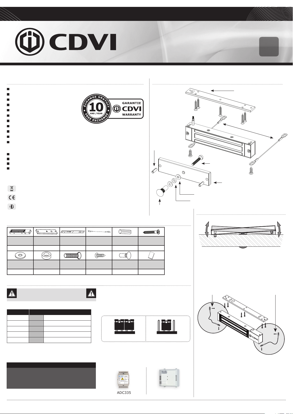
Goupille
Écrou borgne
Plaque de montage
Filins de sécurité
Vis M5
Contre-plaque
Rondelle acier
Rondelle caoutchouc
RECOMMANDATIONS DE MONTAGE
Ventouse saillie
1 1 1 2 2 8
Rondelle
acier
2 1 1
Contre-plaque
Rondelle
caoutchouc
Plaque de
montage
Vis M5x35 Vis 4,8x16 Écrou borgne Notice
RACCORDEMENTS
Réglage usine 12 V DC
Fils Correspondance
Rouge + 12 ou 24V dc
Blanc - - 0 V
Jaune NC Normalement fermé
Bleu C COM
Orange NO Normalement ouvert
Le signal NO/NC ne commute que lorsque la porte
est fermée et sous tension.
NOTE IMPORTANTE
Vérier la position du cavalier avant de brancher
la ventouse au courant d’entrée. Une position
incorrecte peut endommager la ventouse. Ce type
de dommage n’est pas couvert par la garantie.
Toutes les informations mentionnées à titre indicatif sur le présent document (photos, dessins, caractéristiques techniques et dimensions) peuvent varier et sont susceptibles de modications sans notication préalable.
Filin de
sécurité
Goupille 5x16 Vis bois 3,5x25
2 1 1
Cavaliers de sélection de tension
12V DC
Alimentations préconisées
ADC335
G0301FR1036V01
24V DC
BS60
Contre-plaque
- Il est vital de xer solidement la ventouse et la
contreplaque sur leurs supports.
- La ventouse et la contre-plaque doivent être
impérativement alignées.
- La contre-plaque doit être montée “ottante”
autour de la vis centrale de montage pour
compenser un mauvais alignement de la porte.
Filins de sécurité
(xations sur ventouse et bâti)
Les lins de sécurité
La ventouse électromagnétique subit tout au long
de sa vie une accumulation de chocs répétés et de
sollicitations aux niveaux des points de xation sur
le dormant, fréquences d’ouvertures/fermetures,
(tentative d’ouverture porte verrouillée et tentatives
de vandalisme) ce qui peut générer sa désolidarisation
du support au moment de l’ouverture. An de pallier
au risque de chute du bloc ventouse, installer les deux
lins de sécurité fournis pour garantir la sécurité des
utilisateurs (voir schéma ci-dessus).
Page 2
V1SR
166x20x4mm
166x34,5x21mm
130x32x9mm
166
34,5
166
20
180 Kg Surface Mount Electromagnetic lock
EN
PRODUCT PRESENTATION
Monitored
Surface mount
High Corrosion resistance
Safety Rope
Delivered with armature
No mechanical wear
Ease of installation
Recommended for interior use
Fail safe (Door unlocked when power off)
Holding force: 180 kg
Built-in varistor: Built-in electronic protection
to eliminate back EMF
Dimensions (L x W x D): 166 x 34,5 x 21mm
Armature dimensions (L x W x D): 130 x 32 x 9mm
Power supply: 12/24V dc
Power absorption: 12 V DC = 600 mA
24 V DC = 300 mA
WEEE & RoHS
EC certication
IP42
PACKAGE CONTENTS
INSTALLATION
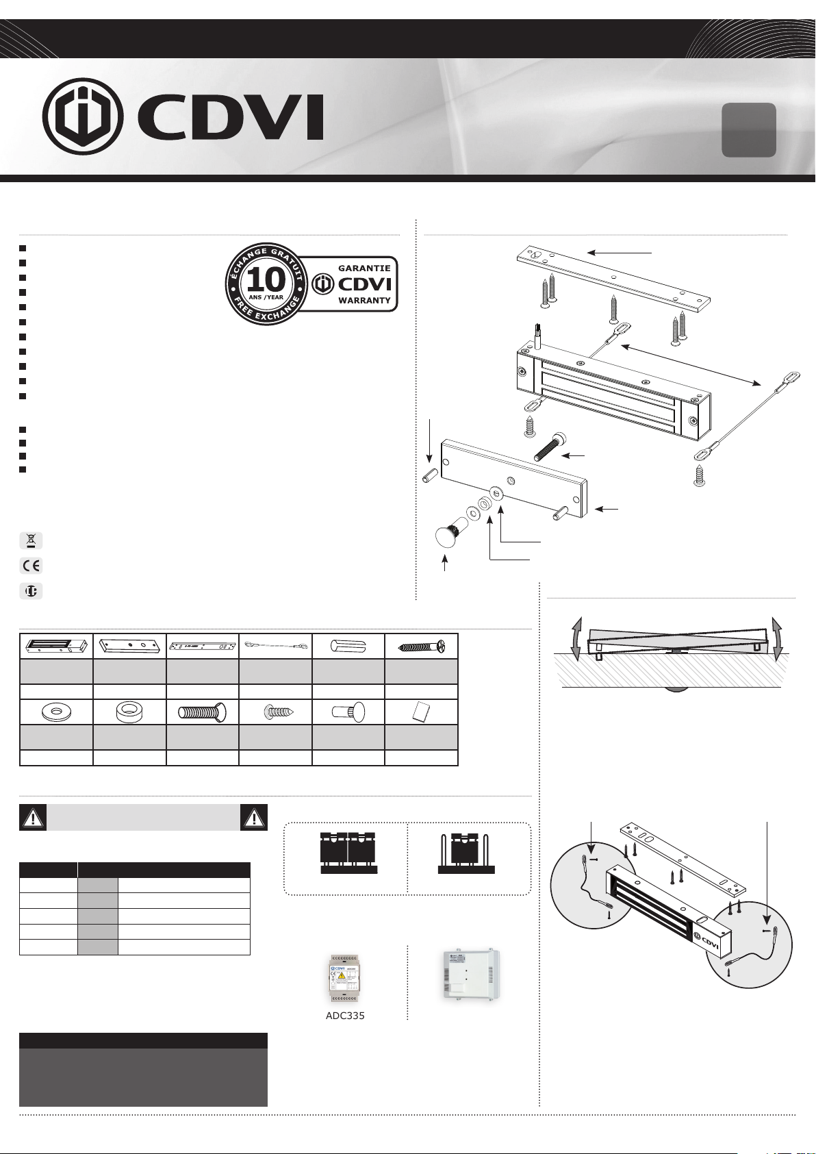
Roll pin
Cap nut
Fixing plate
Security rope
M5 Screw
Fixing plate
Steel washer
Rubber washer
MOUNTING RECOMMENDATIONS
Magnetic lock
1 1 1 2 2 8
Steel washer Rubber washer M5x35 screw 4,8x16 screw Cap nut Manual
2 1 1
Armature
plate
Fixing plate Security rope Roll pin 5x16
2 1 1
Wood screw
3,5x25
ELECTRICAL CONNECTIONS
12V dc default setup
Wires Correspondance
Red + 12 or 24V dc
White - - 0 V
Yellow NC Normally closed
Blue C COM
Orange NO Normally open
The N.O./N.C. signal only switches when the door is
closed with the power to it on.
IMPORTANT NOTE
Check the jumper position before connecting the
lock to the input current. A wrong position could
damage the lock. This type of damage is not
covered by the warranty.
All the information contained within this document (photos, drawing, features, specications and dimensions) could be perceptibly different and can be changed without prior notice.
Voltage selection jumpers
12V dc
Recommended power supplies
ADC335
G0301FR1036V01
24V dc
BS60
Armature plate
- It is vital to x the electromagnetic lock and
armature plate solidly on their supports.
- Make sure that the magnet and the armature
meet evenly over their entire mating surfaces.
- The armature plate must be able to pivot slightly
about its center mounting screw to compensate
for any door misalignment.
(xing on the magnetic lock and the frame)
Security ropes
The electromagnetic lock undergoes repeated
shocks and the vibration at the points of xation
on the frame (frequencies of openings / closures,
attempt of opening wears closed and attempts
of vandalism) which can loosen the xing bolts/
screws.
To prevent the risk of the electromagnetic block
from falling, install both security ropes supplied,
to guarantee the safety of the users (see plan
above).
Security rope
 Loading...