

CDVI SEL2641R433-IP Instruction Manual
Manufacturing Access Control since 1985
www.cdvi.ca
2-Relay Wireless Receiver
SEL2641R433-IP
Instruction Manual
RECEIVER INTRODUCTION
The 2-relay stand-alone wireless receiver SEL2641R433-IP is a
superheterodyne single conversion receiver with integrated rollingcode decoding. The receiver can control devices like; parking gates,
garage doors, multi-bay service centers, lighting, etc.
SPECIFICATIONS
Memorization: Up to 85 transmitter keys.
Self-learning and erasing of
the transmitter code without
accessing to the receiver board
Outputs: 2 (1NO, 1NO or NC)
Pulse, latched or timed
(from 1 sec. to 10 hours)
Operating frequency: 433 MHz
Power supply : 12 or 24 Vac/dc
Current consumption: 25 mA (relay activated: 55 mA)
Operating temperature: -20 to +70 °C
Dimensions: 105 x 45 x 28 mm
Weight: 65 g
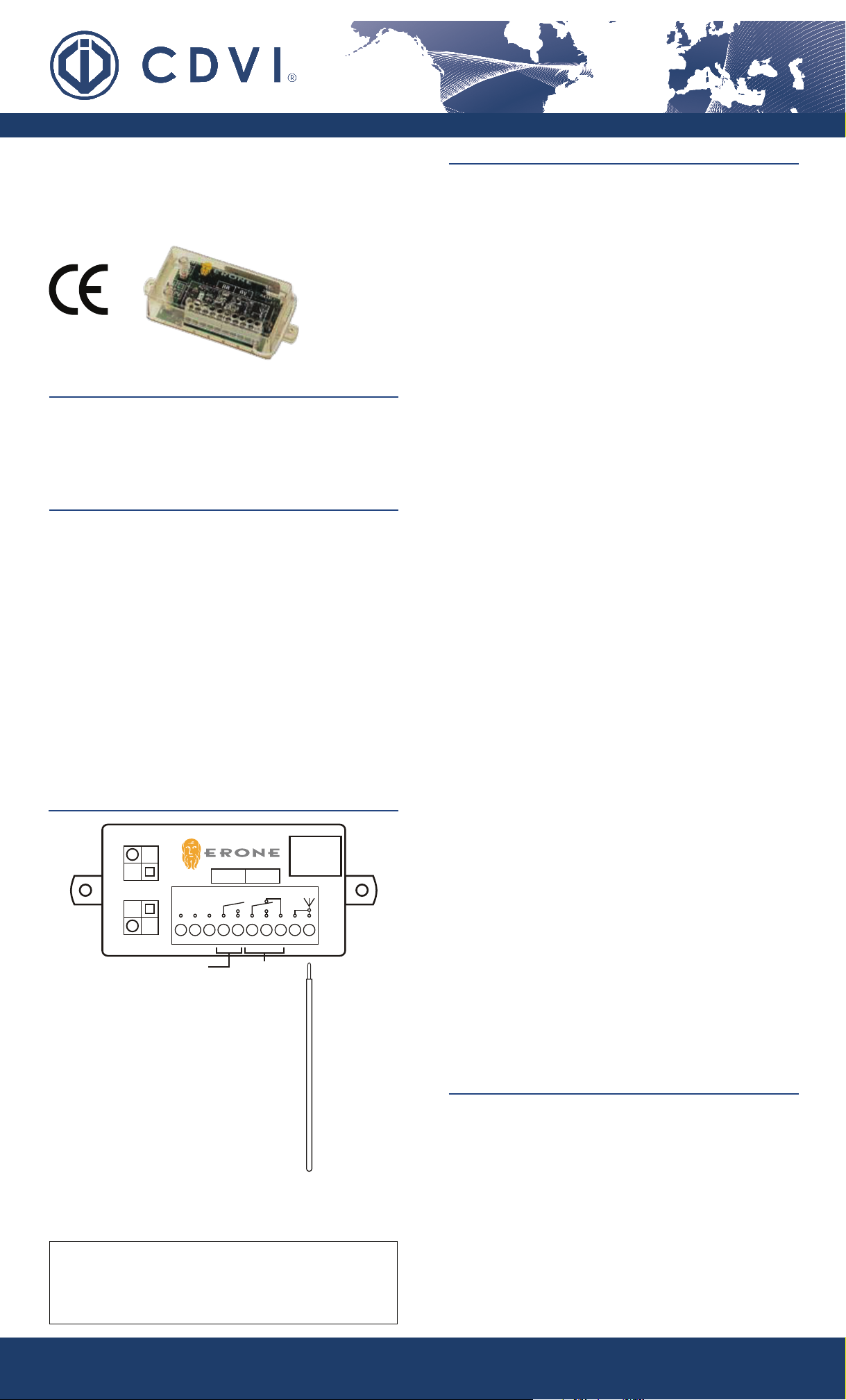
TERMINAL CONNECTIONS
PR
LR
LV
PV
-
AC/DC
12V0V 24V
+
21
+
3
NO NCNO
C C
5
4
RVRR
6
1098
7
TRANSMITTER MEMORIZATION
Transmitter keys can be memorized in 2
different ways:
a) Locally, at the receiver, using PR or PV push-buttons.
b) Remotely, using transmitter keys.
a) Locally at the receiver
To activate Relay 1 (RR)
1) Press PR until LR LED turns ON, then release PR
2) Within 2 sec. press the key of the transmitter you want to
memorize. LR LED will ash and relay 1 (RR) will activate for a
while.
3) Press the key of the transmitter again to verify relay 1 (RR) activation, LR LED will turn ON and LV LED will ash.
At each activation, and for all the transmission time, LR LED will
turn on , LV LED will ash and relay 1 (RR) remains activated.
To activate Relay 2 (RV)
1) Press PV until LV LED turns ON, then release PV
2) Within 2 sec. press the key of the transmitter you want to
memorize. LV LED will ash and the relay 2 (RV) will activate for
a while.
3) Press the key of the transmitter again to verify relay 2 activation,
LR LED will turn ON and LV LED will ash.
At each activation, and for all the transmission time, LV LED will
turn on , LR LED will ash and relay 2 (RV) remains activated.
b) Remotely
Note: One transmitter (two keys) have to be programmed locally to be
able to programmed other transmitter keys remotely.
1) Press both keys of the transmitter that is already stored in the
receiver until the receiver “beeps”;
2) Release both keys and immediatlely press A or B key to select
the corresponding relay to be programmed and hold key for 4
seconds. Relay LED will turn on and “beep” will be continuous
3) Within 2 sec., press the new transmitter key to be memorized.
Example:
Transmitter 1 (TX1) already stored, transmitter 2 (TX2), key A= Realy 1
(RR) and key B= Realy 2 (RV)
Press keys A & B of TX1 (bip); Press key A of TX1 for 4
sec.(Biiiiiiiip); Press key A of TX2 within 2 sec.
Press keys A & B of TX1 (bip); Press key B of TX1 for 4
sec.(Biiiiiiiip); push key B of TX2 within 2 sec.
Relay 1
LR: Red LED (RR: Relay 1)
LV: Green LED (RV: Relay 2)
PR: Push button for relay 1
PV: Push button for relay 2
1: 0V (GND)
2: 12 Vac/dc power supply
3: 24 Vac/dc power supply
4: Common relay 1 (RR)
5: N.O. relay 1 (RR)
6: Common relay 2 (RV)
7: N.O. relay 2 (RV)
8: N.C. relay 2(RV)
9: Antenna Shield
(used for SEA433 tuned antenna)
10: Antenna Core
Relay 2
Supplied
Antenna
WARRANTY
The warranty period for this product is 24 months, beginning from the manufacturer date.
During this period, if the product does not work correctly, due to a defective component,
the product will be repaired or substituted at our discretion. The guarantee does not cover
the plastic container integrity. After-sale service is supplied at the factory.
NOTE : Memory capacity is 85 transmitter keys. A 4-keys transmitter
needs 4 memory positions, if all 4 keys are used. The receiver memory
is full when, at the end of step 2 of transmitter memorization, LV and
LR LED ash 3 times. A transmitter key can not activate both relay (RR
and RV).
TRANSMITTER KEY OVERWRITE
NOTE : Before starting, obtain the memory position and relay
activation (1 or 2) of the transmitter key you wish to overwrite. See
“Memory Psition” section.
1) Press down PR or PV for 4 sec. until the corresponding LED
remains lit, then release it.
2) Within 2 sec., press down PV for 1 sec. (LED will turn off)
3) Within 2 sec., start to enter the memory position sequence by
using PR (red LED) and PV (green LED). See memory position
table.
4) At the end of the sequence LV or LR LED will turn on.
5) Within 4 sec., press the key of the new transmitter you wish to
memorized. This new transmitter key will overwrite the old one.
For more information, please visit www.devancocanada.com or call toll free at 855-931-3334
www.cdvi.ca

Manufacturing Access Control since 1985
RELay CONfIgURaTION
RELAY STATUS:
Note: The receiver factory default setting is pulse for both relay
Press down PR or PV for 4 sec. and note the LED state (LR or LV).
The following table determine the relay status :
Relay operating mode
( RR or RV )
Pulse LED ON
Latched (RR only) Slow blinking
Timed Fast blinking
RELAY SETTING:
The relay operating mode is cyclic, change the mode according to the
following rules:
Relay operating mode cycle
If the relay is set as pulse 1- it becomes latching
If the relay is set as latching it becomes pulse
If the relay is set as timed it becomes pulse
LED operating mode
( LR or LV )
2- it becomes timed if you press
the timing sequence after step 2
MEMORy pOSITION
1) Press transmitter key to verify if its associated to the receiver. LR
or LV will turn ON and the related relay will activate.
2) Press and hold PR for 1 sec. and then release it. A sequence
of 7 ashes of the LEDs (LR and LV) starts. Note the LED color
sequence. Refer to the following table to decode the sequence.
Flash sequence 1 2 3 4 5 6 7
LV (green LED) 1 2 4 8 16 32 64
LR (red LED) 0 0 0 0 0 0 0
LR=0 all the time.
Add the value of LV (where it ashes in the sequence) to obtain the
memory position. See example below.
Example 1:
Flash sequence 1 2 3 4 5 6 7
LV (green LED) - -
LR (red LED)
Sequence Value 0 0 4 8 0 0 0
Memory position= 0 + 0 + 4 + 8 + 0 + 0 + 0= 12
The transmitter key is located at memory position #12.
Flash Flash
Flash Flash
- -
- - -
Flash Flash Flash
Relay Conguration Not Allowed
Relay 1 (RR) latching and Relay 2 (RV) timed
Relay 1 (RR) timed and relay 2 (RV) timed (with different delay time)
To change the mode follow these steps:
1) Press PV or PR for 4 seconds. LED will illuminate displaying relay
status. Use Table above to determine the status.
2) Within 1 sec., press PR to change the relay mode. The relay
mode will change according to the relay setting table above.
Note: To congure the relay output time, enter the timing sequence
after step 2, see relay timing table below.
RELAY TIMING:
Important: To set or modify relay timing, the relay has to be set as
pulse before.
1) Press PR for 4 sec. The LR LED will turn ON (if not, set the relay
operation to pulse, see Relay Setting section).
2) Press PR for 1 sec. and LR LED switche to OFF. Within 2
seconds, start the seven digit, PR and PV sequence, to set the
relay timing (See table below)
PR= not seclected (0) PV= selected (1)
Pressing sequence 1 2 3 4 5 6 7
Seconds
Minutes
1 2 4 8 16 PR PR
10 20 40 80 160 PV PR
2 4 8 16 32 PR PV
20 40 80 160 320 PV PV
ENROLLED TRaNSMITTER kEyS
1) Press down PV for 1 sec. LR and LV LED starts a sequence of 7
ashes. Note the color sequence and refer to the above table to
obtain the number of enrolled transmitter keys.
MEMORy RESET (faCTORy DEfaULT )
1) Press PR until LR LED turns on.
2) Release PR and within 1 sec. press PR and PV simultaneously
until LR and LV LED starts to ash 3 times (about 4 sec.)
At this point all settings are erased and the receiver is reset to factory
default.
COMpaTIbLE TRaNSMITTERS
2-Channel Transmitters
S2TR2641E2
Available with built-in
proximity badge
S2TR2641E2H
4-Channel Transmitters
S2TR2641E4
2-Channel Mini Transmitters
Red: SETR2641AM2R
Blue: SETR2641AM2B
Burgundy: SETR2641AM2C
Dark Gray: SETR2641AM2N
Example 1: 8 sec. relay activation
Pressing sequence 1 2 3 4 5 6 7
Seconds
Minutes
Input sequence= PR + PR + PR + PV + PR + PR + PR= 8 sec.
Example 2: 2 min. relay activation
PR and PV
pressing sequence
Seconds
Minutes
Input sequence= PV - PR - PR - PR - PR - PR - PV= 2 min.
For more information, please visit www.devancocanada.com or call toll free at 855-931-3334
Tel: (450) 682-7945, Toll Free Tel: 1-866-610-0102, Fax: (450) 682-9590, Toll Free Fax: 1-866-682-9590
SEL2641R433-IP_IE - Specications may change without prior notice. Printed in Canada - 15/11/07
PR PR PR PV PR PR PR
10 20 40 80 160 PV PR
2 4 8 16 32 PR PV
20 40 80 160 320 PV PV
Available with optional
built-in proximity badge
faCILITy CODE aND SERIaL NUMbER LOCaTION
1 2 3 4 5 6 7
1 2 4 8 16 PR PR
10 20 40 80 160 PV PR
PV PR PR PR PR PR PV
20 40 80 160 320 PV PV
Facility code (FC)= 001 Serial Number (SN)= 28886
CDVI® 1645-A Highway 440 West, Laval, Québec, Canada, H7L3W3
2-Channel
Ultra-Thin Transmitters
S5TR2641E2S
4-Channel
Ultra-Thin Transmitters
S5TR2641E4S
 Loading...