

Over-voltage protection
Over-current protection
Short circuit protection
Over charge protection
Over discharge protection
Self-recovery when fault condition remove
Protection
Caution
All c onten t, spec ifica tions a nd avai labil ity sub ject to c hange w ithou t prior n otice .
CAUT IO N
Non -prof essio nal mai ntena nce
do no t disas sembl e
-
using.
- The U PS i s to b e in st al le d in a c on tr ol le d en vi ro nm en t.
- Only suited for permanently powered systems.
- Make sure the power supply is well ventilated.
- It is mandatory to ground the power supply.
- Use 2,5 mm gauge cable.
- Improper storage and installation environmen t ma y de te ri or at e in su la ti on ,
shorten components life and cause malfunctions.
Make sure the power supply input voltage and the local gri d vo lt ag e ma tc hi ng b ef or e
2
- Read carefully this user guide before activating and u si ng .
- Use this equipment only for an indoor adapted applic at io n.
- Mounting, maintenance and repair must be carried on by a ski ll ed a nd a ut ho ri ze d st aff .
- The a ct iv at io n is e as y, bu t a co rr ec t ha nd li ng a nd a n ap pr op ri at e ma in te na nc e ar e
mandatory to keep the power supply working perfectly.
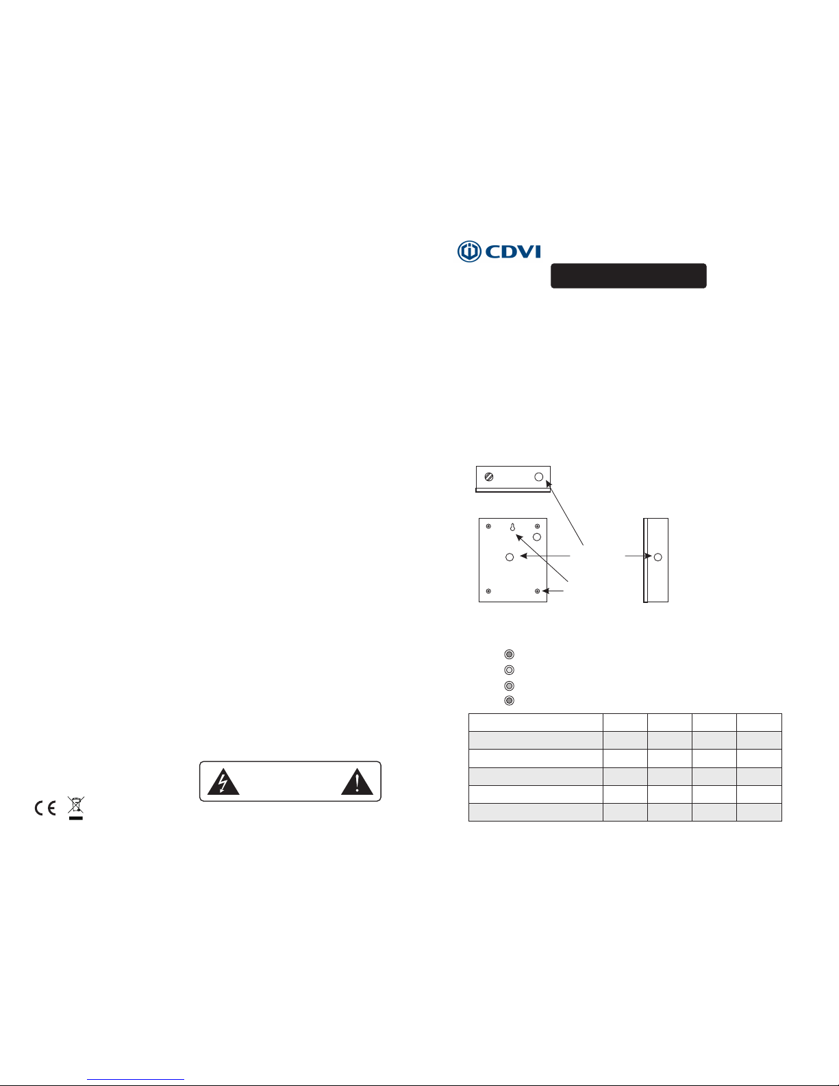
Mounting
The UPS must be mounted firmly and securely.
LED description
AC POWER
DC OUTPUT
BATT ERY CHA RG E
③Amber
②Green
BATT ERY LOW V OLTAGE
④Red
①Red
PS1A 12V S - - PS2A 12V S PS3A 12V S - PS5A1 2VS
Cable Entry
Mounting Holes
Rear view
Right side view
Top view
User Guide
Situation
Battery in full charged
No AC, V-battery > 11±0. 3V
No AC, 1 0±0.3V< V-batt ery<11±0 .3 V
Battery in charging
No AC, V-battery < 10±0.3V
①RED ②GREEN ③AMBER ④RED
on on
off
on on
flash off
off
on
off
off
off off off off
on on
on
on
on

Terminal description
B: AD JU STA BL E OU TP UT VO LTAG E
A: B ATT ERY AC TI VATIO N SW IT CH
*Based on the premise that the load can work normally, out pu t vo lt ag e re gu la ti on i s su gg es te d be tw ee n 13 .8 V to 1 4. 0V. B at te ry c an b e fu ll y ch ar ge a nd p ro lo ng t he
service life under this situation.
Main specification
BATT ERY
NL GND
ON OFF
12V- 14V
AC IN PUTINP UT SWIT CH
DC OU TPUT
A B
-20 ~+45 De gree Ce lsius
Up to 9 0% non- Conde nsing
AC su pply:
Out put vol tage - on m ains po wer:
Max . outpu t curre nt:
Max . charg e curre nt:
Ope ratio n tempe ratur e:
Hum idity :
Bat tery co mpart ment:
Out put vol tage - on b atter y stand by:
BATT ERY
NL GND
ON OFF
12V- 14V
AC IN PUTINP UT SWIT CH
DC OU TPUT
A B
*Before connecting to AC po we r fo r th e fi rs t ti me , th is s wi tc h ca n be u se d fo r ac ti va ti ng b at te ry ; Aft er c on ne ct in g to A C po we r, ba tt er y wi ll b e ac ti va te d au to ma ti ca ll y
in each AC po we r fa il ur e, w it ho ut p us hi ng t hi s sw it ch .
PS1A 12V S
PS5A 12V S
L
GND
N
BATT ERY
NL GND
ON OFF
12V- 14V
AC IN PUTINP UT SWIT CH
DC OU TPUT
A B
PS2A 12V S / PS3A1 2VS
100 -240 V ac 5 0/60H z
12. 0-14. 0 V dc adju stabl e
1.0 A
0.8 A
7Ah /12V
10. 0-12. 5 V dc
100 -240 V ac 5 0/60H z
3.0 A
0.8 A
7Ah /12V
12. 0-14. 0 V dc adju stabl e
10. 0-12. 5 V dc
2.0 A
0.8 A
7Ah /12V
12. 0-14. 0 V dc adju stabl e
10. 0-12. 5 V dc
PSU12-1SM PSU12-2SM PSU12-3SM
100 -240 V ac 5 0/60H z
 Loading...