

Page 1
2-wire Intercom System
2 EASY
1 2 3
654
7 8 9
#0
*
RF CARD
CONTENTS
INTRODUCTION...........................................................................2
Installation Guide........................................................................2
CONFIGURATIONS......................................................................4
Debug State...............................................................................4
Work Mode.................................................................................8
Software Update........................................................................10
Tone Update..............................................................................10
UI Update...................................................................................11
Namelist Update.........................................................................12
CDV-DDPs TECHNICAL MANUAL
by SD Card..............................................................................12
by CDV-Cong............................................................................13
Page 2
2 EASY
DESCRIPTION MOUNTING
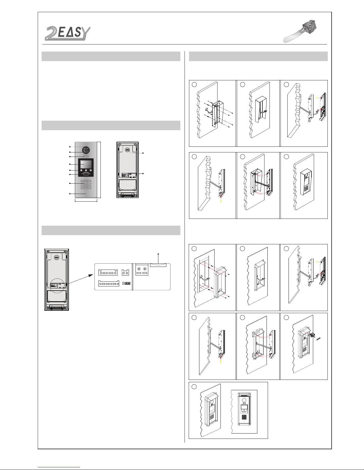
PARTS AND FUNCTIONS
Camera Lens
Night View LED
Speaker
Adjustable Camera
350 mm
128 mm
1 2 3
654
7 8 9
#0
*
LCD Screen
ID Card Window
Digital Keypad
Microphone
12
3
Touch Key
RF CARD
TERMINAL DESCRIPTION
L1
T/R -
CN-LK
T/R+
J/KMB JP-LK
Bus
SD Card Slot
EB+
EB-
N.O
LK+
LK-
+12V
L2
12
3
12
3
•
+12V:
12VDC power output.
•
LK-(GND):
Power ground.
•
LK+(COM):
Common contact of the relay .
•
NO.:
Normally open contact of the relay(refer to DT technical
guide for detail informations about lock connection).
•
EB+:
Exit button connection port.
•
EB-:
Exit button connection port.
•
JP-LK:
For electronic lock safety type setting(refer to door
station lock connections).
•
T/R-:
USB-RS485 communication terminal negative.
•
T/R+:
USB-RS485 communication terminal positive.
•
Bus(
L1,L2): non-polarity bus line.
Surface mounting
Flush mounting
1 2
4 5 6
Drill holes in the wall to match the size of
screws and attach the rainy cover to the wall.
Attach screws to fix the metal box
Attach the unit to the rainy cover correctlly
The last view for all mounting
The view for rainy cover after mounted.
Adjust the camera angle and attach the
metal to the panel and wire correctly.
Camera
angle
3
1 2 3
4
7
5 6
Drill a hole and attach the rainy
cover to it
Attach screws to fix the metal
box
Attach the unit to the
rainy cover correctlly
Attach the baffle to protect
the unit from droping
The last view for all mounting
The view for rainy cover
after mounted
Adjust the camera angle and attach the
metal to the panel and wire correctly.
Camera
angle
1
47
m
m
3
95
m
m
4
2mm
RF CARD
DMR18S Technical Menu-2-
INTRODUCTION:
Installation Guide
Connection Port
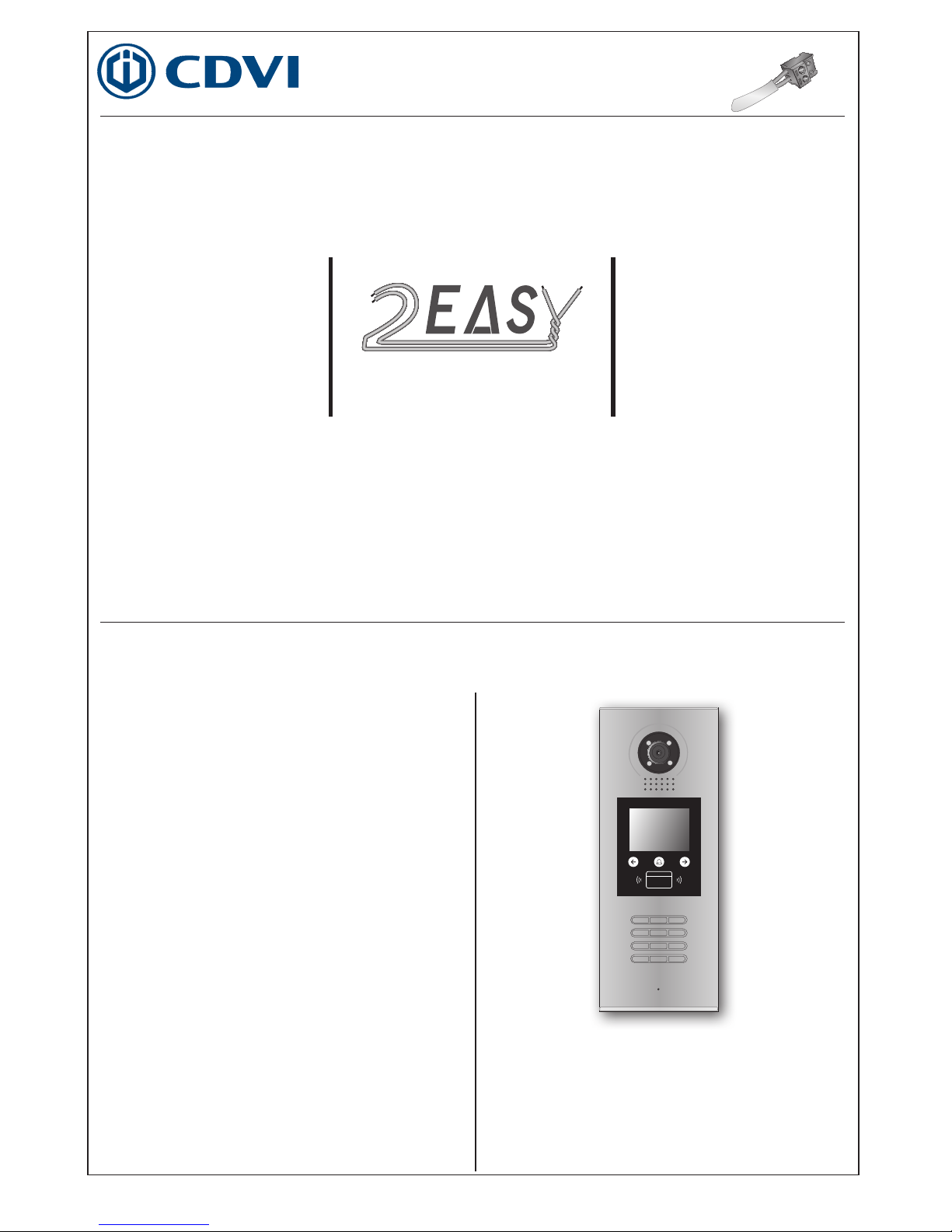
As an upgrade of the CDV-DDP, the CDV-DDPs
provides
stability and
stronger communication. It can call up of 128 families expanding the
capacity of the system. It also adds many special functions, such as
selection by use of a touch sensitive keypad for the name list, voice
prompt etc. , bringing clients fresh and modernised experience. For
convenience users can upgrade the User Interface(UI) and voice
prompt through use of an SD card themselves.
Page 3
2 EASY
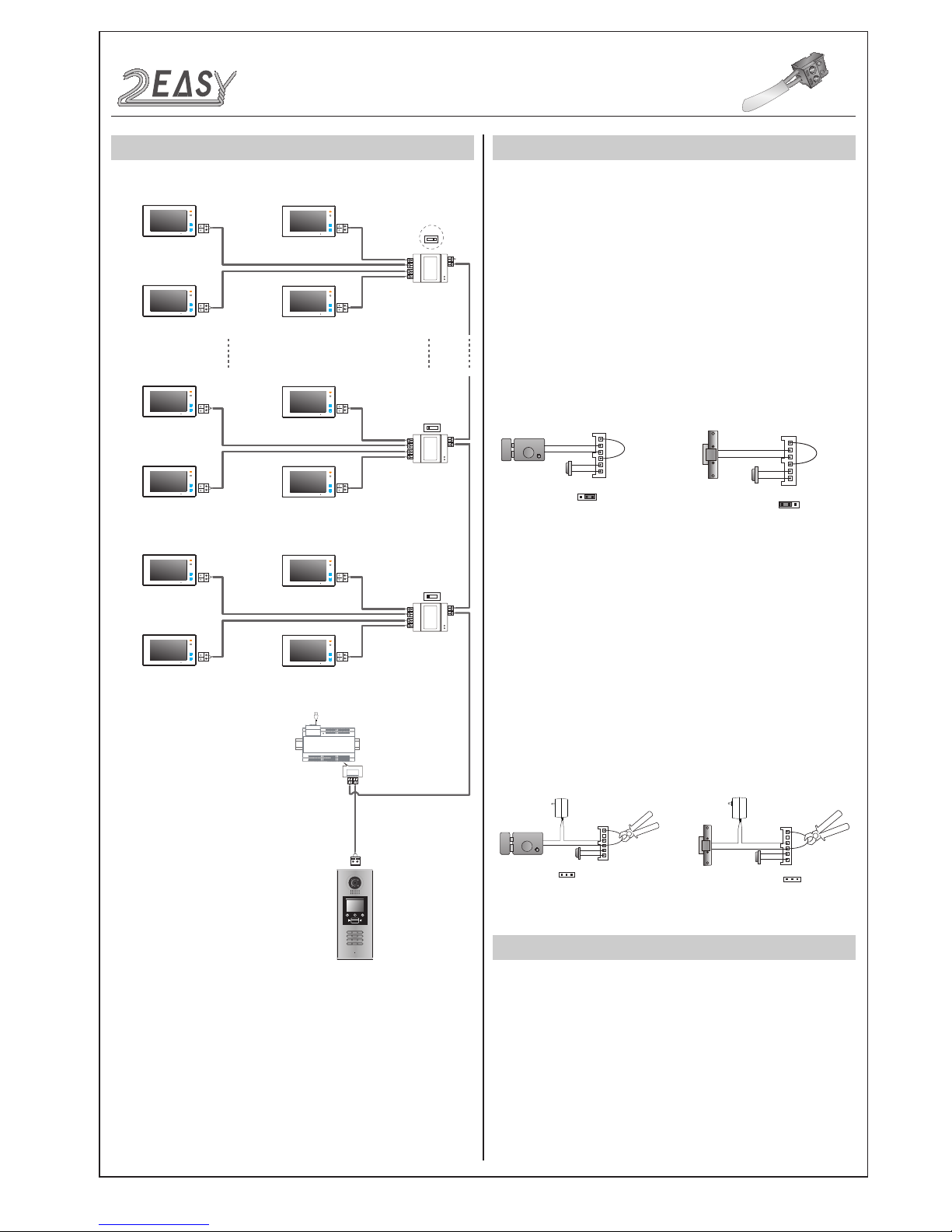
SYSTEM CONNECTION
OFF ON
OFF ON
DBC4A
A B C D
DBC4A
A B C D
Impedance
switch
Impedance
switch
100~240VAC
BUS(IM) BUS(DS)
PC6
AC~
OFF ON
DBC4A
A B C D
Impedance
switch
Code=28
Code=30
Code=29
Code=31
Code=4
Code=6
Code=5
Code=7
Code=0
Code=2
Code=1
Code=3
1 2 3
654
7 8 9
#0
*
RF CARD
ELECTRIC LOCK CONNECTION
1) Door Lock Controlled with Internal Power
1. The door lock is limited to 12Vdc, and holding current must be less
than 250mA when using internal power supply mode.
2) Door Lock Controlled with External Power
• Power-on-to-unlock type:Unlock Mode=0(by default)
• Power-off-to-unlock type:Unlock Mode=1
JP_LK
12V 300mA
Exit button
Jumper position in 2-3
+
-
+12V
LK LK+
N.O.
EBEB+
1 2 3
Power-on-to-Unlock type:
12V 300mA
Jumper position in 1-2
+12V
LK LK+
N.O.
EBEB+
+
-
JP_LK
1 2 3
Exit button
Power-off-to-Unlock type:
+
+
-
-
+12V
LK - (GND)
LK+(COM)
N.O.
EBEB+
JP_LK
Cut off the line
1 2 3
Exit button
+12V
LK - (GND)
LK+(COM)
N.O.
EBEB+
+
+
-
-
JP_LK
Cut off the line
1 2 3
Exit button
SPECIFICATION
• Power supply: DC24V
• Camera Lens: 1/4 ACS 4T image sensor
• Power consumption: Standby 33mA; Working status 157mA.
• Screen: 3.5 inch TFT
• Resolution: 320(R, G, B)X240 pixels
• Video signal: CCIR/EIA optional
• Wiring: 2 wires, non-polarity
• Dimension: 350(H)×128(W)×46(D)mm
• Note: The diagram take the monitor of DT47M for example.
DMR18S Technical Menu -3-
2. The Unlock Mode Parameter must be set to 0 (by default).
3. Jumper set to position 1 & 2 for power-off-to-unlock, fail safe
(Relay-no
rmally closed mode
); set to position 2 & 3 for
power-on-to-unlock type, fail secure (Relay n
ormally open mode
).
4. If a different unlocking time is required, change the unlock time
at the door station, for detailed information refer to the 2Easy
system technical guide.
1. The external power supply must be used in accordance to
lock current required.
2. The jumper JP_LK must be removed before connecting.
3. Setup of the
Unlock Mode Parameter
for different lock types
4. If different unlocking time is required, change the unlock time at
the door station, for detailed information refer to 2 Easy system
tech- nical guide .
Remove Jumper
Remove Jumper
Power-off-to-Unlock type - Mode 1:Power-on-to-Unlock type - Mode 0 (Default):
INTRODUCTION
Installation Guide
Page 4
2 EASY
Installer setup page
overview.
Descriptions:
0-#: Call Monitor again
2-#: Exit out Debug State
0 : Power-on-to-unlock mode
1 : Power-off-to-unlock mode
Descriptions:
[ 9 0 0 8 ]
Please Input Password
1 2 3
654
7 8 9
#0
*
RF CARD
>> Debug State <<
0-# Redial
1-# Tools
2-# Exits
DEBUG STATE
INSTALLER SETUP
TALK VOLUME ADJUST
Pres NO.
to select
*Back
Tools
Press No.
to select
*Back
Installer
Setup
1.Installer Setup
2.Setup
3.Card Manage
4.Online Monitors
5.Online Devices
6.Voltage Measure
1. ID Code [0]
2. Unlock Timing [01]
3. Unlock Output [0]
4. Monitor Timing [600]
5. Doorplate Mode [0]
6. Waiting Timing [040]
7. Talking Timing [090]
8. Installer Code ...
9. Default ...
>> Debug State <<
0-# Redial
1-# Tools
2-# Exits
* Cancel # Save
(0~3)
[ - ]
1. ID Code [0]
* Cancel # Save
(01~99)
[ - - ]
2. Unlock Timing [01]
* Cancel # Save
(0~1)
[ - ]
3. Unlock Output [0]
* Cancel # Save
(0~3)
[ - - - ]
4. Monitor Timing [600]
DMR18S Technical Menu-4-
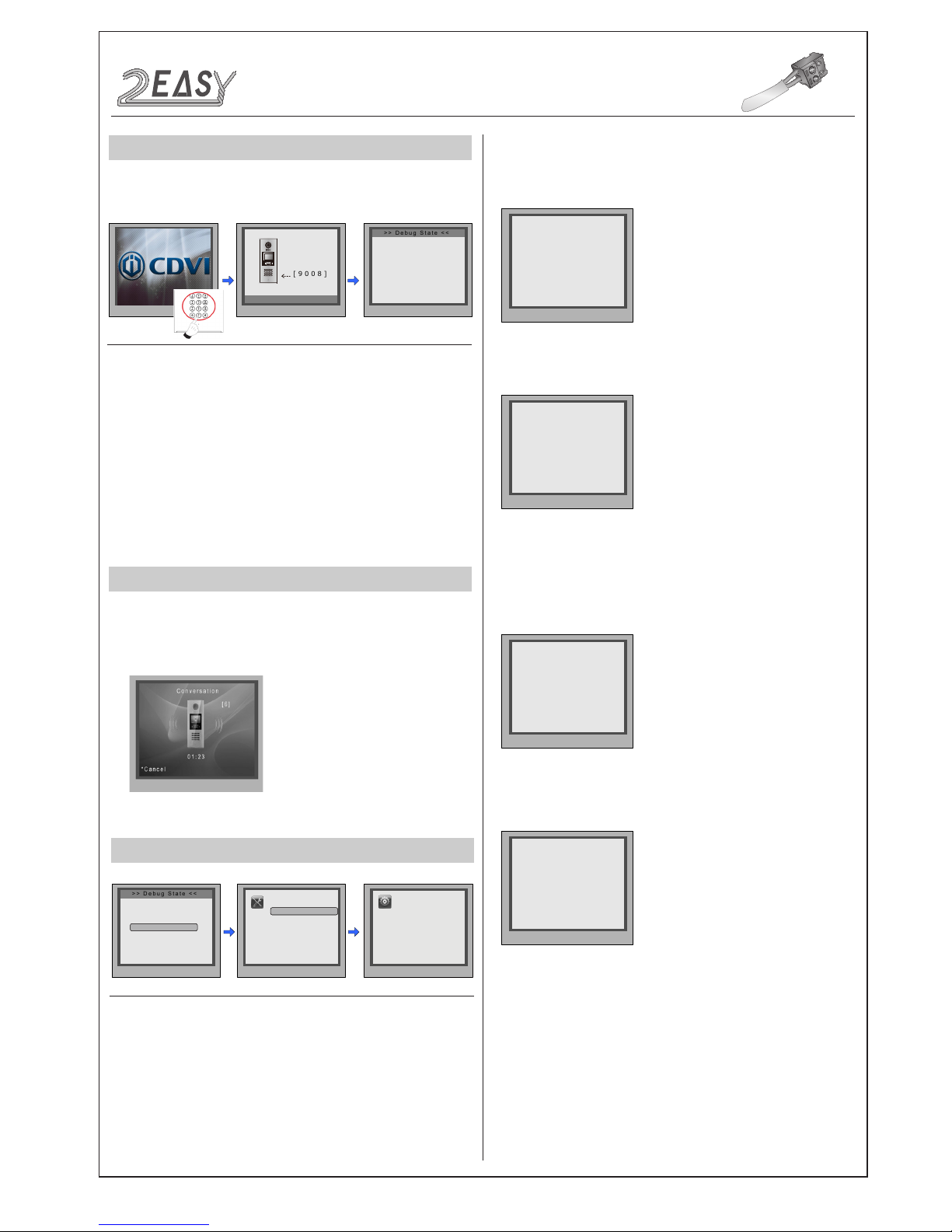
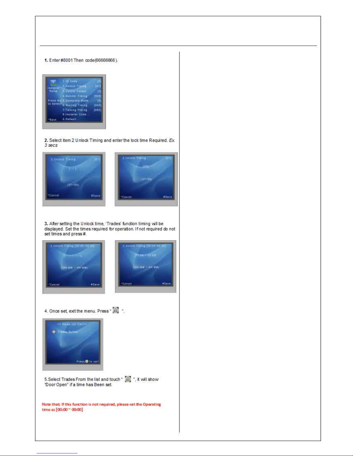
The Debug State is the starting point for using all the applications on
DMR18S.
When door station is in
standby, press '#' key
Enter '9008', then enter the
Admin Code.(66666666
by default)
Debug state menu is
launched
1-#: Go to Tools setting
In
Debug State
, calling and conversation are available, you can
enter 0~9 to select the volume you require, see the following
image.
While working in debug
state, press "1#" to enter
tools page.
0 : Enter the room number to call the monitor
1 : Enter the room number + ‘#’ to call the monitor
* Note: In the diagram -
2) Shows setup of 2 digit calling.
CONFIGURATION
Debug State
Press NO.“1” to enter
'Installer Setup'.
1.ID Code:
Select 1 to enter
ID Code
setting page. You can input
0~3
to set as door 1 ~ door 4.
2.Unlock Timing:
Select 2 to enter
Unlock Timing
setting page,
setting range is from 01~99s.
3.Unlock Output:
Select 3 to enter
Unlock Output
setting page.
4.Monitor Timing:
Select 4 to enter
Monitor Timing
setting
page, the setting range is from 006~600s.
5.Doorplate Mode:
Select 5 to enter
Doorplate Mode
setting
page.
1) “0” mode is used as an example.
Page 5
Page 6
2 EASY
Set 2 digit
number calling
* Cancel # Save
(0~1)
[ - ]
5. Doorplate Mode [0]
* Cancel # Save
[ : : : : : : : : ]
5. Doorplate Mode [11]
Input 0
0: *
1: 123
2: ABC
3: -
* Cancel # Save
[ * * * * * *1 1 ]
5. Doorplate Mode [11]
0: *
1: 123
2: ABC
3: -
* Cancel # Save
(006~600)
[ - - - ]
6.Waiting Timing [040]
* Cancel # Save
(006~600)
[ - - - ]
7. Talking Timing [090]
* Cancel # Save
(********)
[ - - - - - - - - ]
8. Installer Code ...
* Cancel # Save
Please input password
[ - - - - - - - - ]
9. Default ...
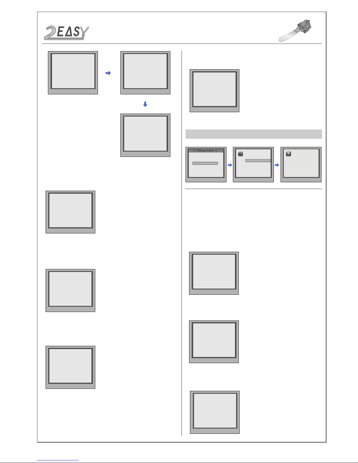
During working at debug
state,press "1#" to enter
tools page.
Press NO.“2” to enter
Setup item.
Setup page overview.
Descriptions:
SETUP
Pres NO.
to select
*Back
Tools
Press No.
to select
*Back
Setup
1.Installer Setup
2.Setup
3.Card Manage
4.Online Monitors
5.Online Devices
6.Voltage Measure
1. Language [0]
2. Tone Select [01]
3. Tone Volume [3]
4. Unlock Code [1111]
5. Work Mode [0]
6. Clock ...
7. Setup Code ...
8. About ...
9. Default ...
>> Debug State <<
0-# Redial
1-# Tools
2-# Exits
* Cancel # Save
1. Language [0]
00 English
* Cancel # Save
2. Tone Select [01]
00 Mute
01 Tune
02 English
* Cancel # Save
(0~9)
[ - ]
3. Tone Volume [3]
9.Default:
Select 9 to enter
Default
setting page. Input the setup
code
to restore factory setting.
6.Waiting Time:
Select 6 to enter
Waiting Timing
setting
page. The setting range is from 006~600s.
7.Talk Time:
Select 7 to enter
Talking Timing
setting page.
The
setting range is from 006~600s.
1.Language:
Select 1 to enter
Language
setting page. Select
the
language you need.(Refer to the following
UI Update
section).
2.Tone Select:
Select 2 to enter
Tone Select
setting page. Select
the
Tone you want. (Refer to the followng
Tone Update
section).
8.Installer Code:
Select 8 to enter
Installer Code
setting page.
(Setting 8 digit numbers).
3.Tone Volume:
Select 3 to enter
Tone Volume
setting page.
The
setting range is 0 ~ 9.
DMR18S Technical Menu -5-
CONFIGURATION
Debug State
Page 7
2 EASY
CONFIGURATION
Debug State
* Cancel # Save
(***)
[ - - - ]
4. Unlock Code [1111]
[ 8002 ]
Please Input Password
1 2 3
4 5 6
*
0 #
RF CARD
3. Tone Volume[03]
4. Unlock Code [1111]
5. Work Mode
6. Clock
7. Setup Code
8. About
9. Default
Press No.
to select
*Back
Setup
2. Tone Select [03]
*Cancel
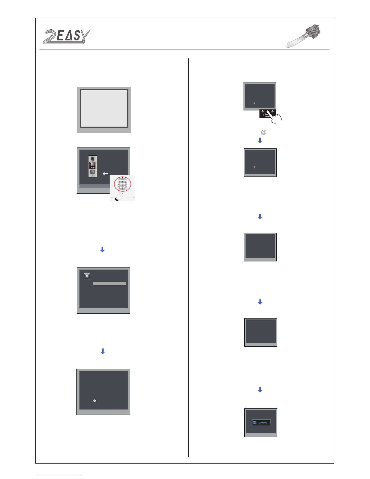
Long press[ ] to enter private code setting
[ - - - - ]
( * * * *)
# Save
1. Language [1]
4. Unlock Code[1111]
Input 4 digits number, then press
“#” to update.
Press “4” to enter unlock code
item.
Press “#”,Input “8002”, then
input Setup Code or Admin
Code (88888888 or 66666666
by default)
4.Unlock Code:
Select 4 to enter
Unlock Code
setting page,
1111 is the default unlock code. Input 4 digit numbers to set a
new code(Except for 8001~8019 and 9008).
At this point a private unlock code can be set, follow the steps below:
(****)
RF CARD
Long press[ ] to enter private code setting
# Save
Long press button.
4. Unlock Code [1111]
[----]
(****)
[009]
Input room number
Setting code: 005
[8888]
Input new password
Setting code: 005
4. Unlock Code [009] [----]
[8888]
Input new password
Setting code: 005
4. Unlock Code [009] [8888]
[005]
Input setting code
Long press[ ] to enter private code setting
# Save
*Cancel
4. Unlock Code [---] [----]
4. Unlock Code
*Cancel
# Save
# Save
# Save
*Cancel
*Cancel
Input setting code
(001~300), then
press “#“ to save.
Input room number,
then press “#“ to save.
Input new password,
then press “#“ to save.
-6- DMR18S Technical Menu
Page 8
2 EASY
Input 0
Input 0
Input time
0 : 32 apartments
1 : 128 apartments
2 : Router
3: Gateway
* Cancel # Save
[ - ]
6. Clock ...
0: DD/MM/YY
1: MM/DD/YY
* Cancel # Save
[ - ]
6. Clock ...
0: 24-Hour
1: 12-Hour
--/--/-- -
--/--
* Cancel # Save
DD/MM/YY W HH/MM
6. Clock ...
* Cancel # Save
DD/MM/YY W HH/MM
6. Clock ...
16/07/15 4
14/13
* Cancel # Save
(0~3)
[ - ]
5. Work Mode [0]
* Cancel # Save
(********)
[ - - - - - - - -]
7. Setup Code ...
* Cancel # Save
Hardware Version
DMR18S-CT a1.1
Software Version
V000101
Manufacture Date
Dailing Count[0006]
Calling Count[0002]
Unlock Count[0005]
2015-06-22
* Cancel # Save
Please input password
[ - - - - - - - - ]
9. Default ...
Card Manage page
overview.
Pres NO.
to select
*Back
Tools
Press No.
to select
*Back
1.Installer Setup
2.Setup
3.Card Manage
4.Online Monitors
5.Online Devices
6.Voltage Measure
1. Add Card ...
2. Delete By Card
3. Delete By M.code
4. Cards Information
5. Format
>> Debug State <<
0-# Redial
1-# Tools
2-# Exits
Card
Memory
Show the card
* Cancel # Save
Please input room code
[ - - - ]
1. Add Card ...
* Cancel # Save
Show the card
[ 0 0 1 ]
1. Add Card ...
* Cancel # Save
Card Numbs.05410469
[ 0 0 1 ]
1. Add Card ...
Input 001
i
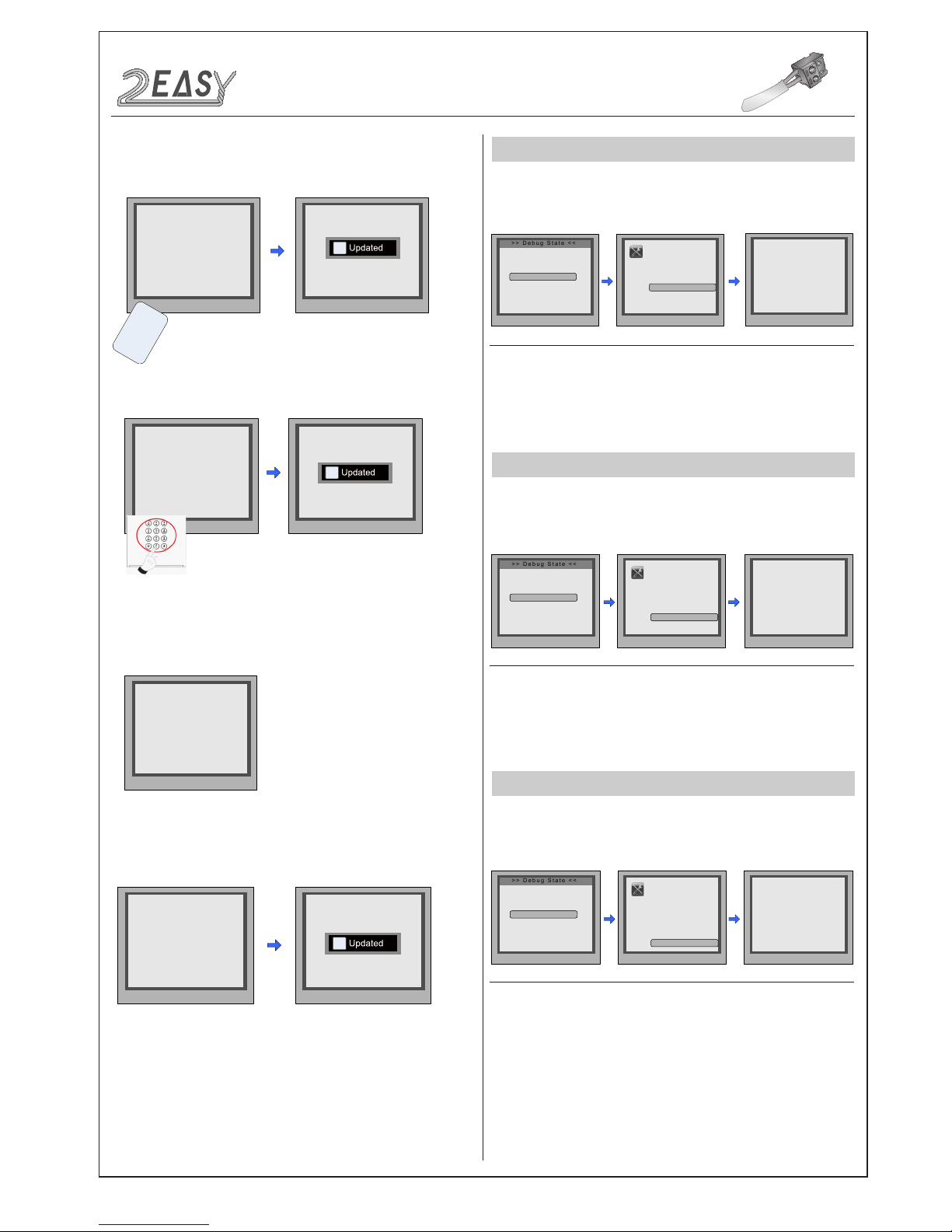
Updated
CONFIGURATION
Debug State
CARD MANAGEMENT
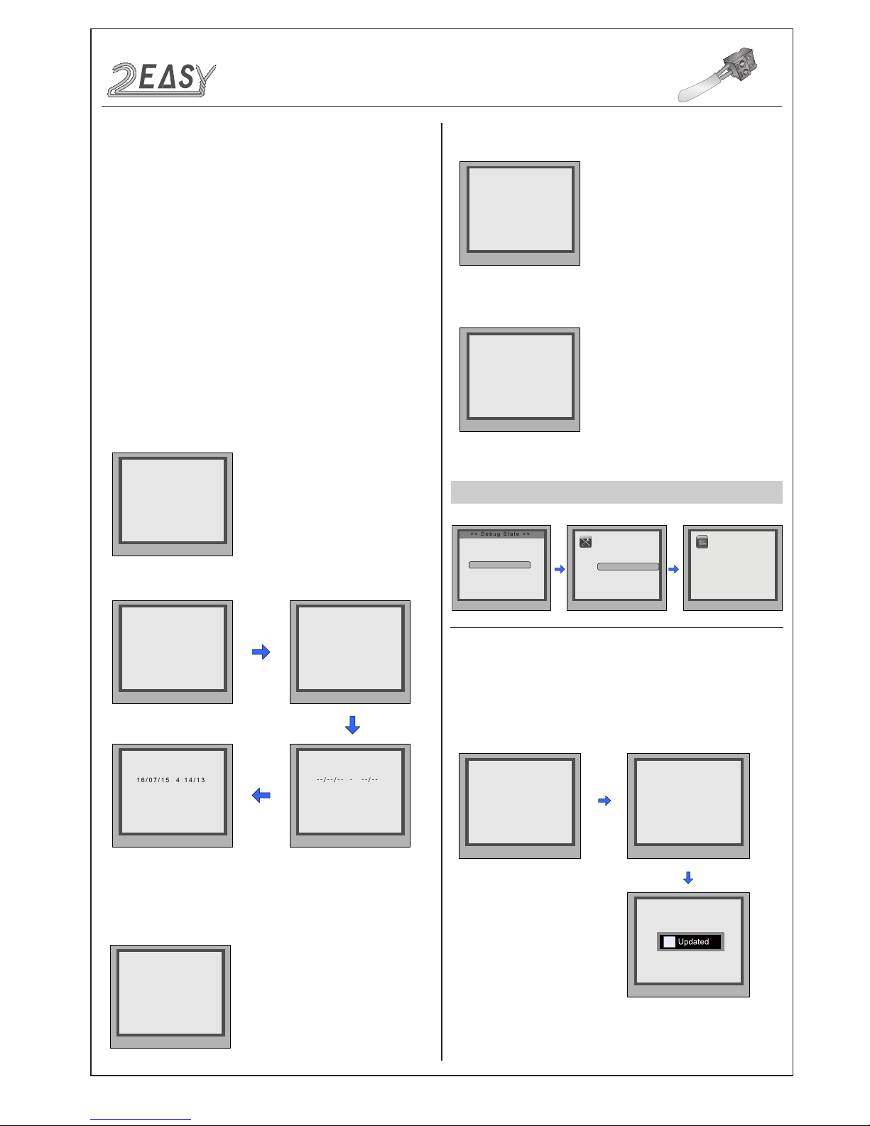
While working in debug
state, press "1#" to enter
tools page.
* Note: the diagram uses “0” mode as an example.
Press NO.“3” to enter
Card Manage'.
8.About:
Select 8 to enter
About
page. The information includes
Hardware version, Software Version etc.
9.Default:
Select 9 to enter
Default
setting page. Enter the
setup
code to restore factory settings.
6.Clock:
Select 6 to enter
Clock
setting page.
1.Add Card:
Select 1 to enter
Add Card
setting page.
7.Setup Code:
Select 7 to enter
Setup Code
setting page. Enter an
8 digit number to set a new setup code, then press ‘#’ to save.
5.Work Mode:
Select 5 to enter
Work Mode
setting page, four
modes are available, the setting range is 0~3.(For more details refer
to the following
Work Mode
section)
DMR18S Technical Menu -7-
Page 9
2 EASY
2.Delete Card:
ONLINE MONITORS
ONLINE DEVICES
During working at debug
state,press "1#" to enter
tools page.
All devices online or
ofine will be showed.
Pres NO.
to select
*Back
Tools
1.Installer Setup
2.Setup
3.Card Manage
4.Online Monitors
5.Online Devices
6.Voltage Measure
>> Debug State <<
0-# Redial
1-# Tools
2-# Exits
* Cancel # Save
4. Online Monitors
(Search Range)
Gateway:[ ]
IM:[ ] ~ [ ]
Pres NO.
to select
*Back
Tools
1.Installer Setup
2.Setup
3.Card Manage
4.Online Monitors
5.Online Devices
6.Voltage Measure
>> Debug State <<
0-# Redial
1-# Tools
2-# Exits
* Cancel # Save
5. Online Devices
[CDS1]: Online
[CDS2]: Online
[CDS3]: Fail
[CDS4]: Fail
Pres NO.
to select
*Back
Tools
1.Installer Setup
2.Setup
3.Card Manage
4.Online Monitors
5.Online Devices
6.Voltage Measure
>> Debug State <<
0-# Redial
1-# Tools
2-# Exits
* Cancel # Save
[ - - ]
6. Voltage Measure
* Cancel # Save
Show The Card
2. Delete By Card
* Cancel # Save
2. Delete By Card
i
Updated
Card numbs:15977131
U
s
e
r
C
a
r
d
* Cancel # Save
Please Input Room Code
3. Delete By M.code
[ - - - ]
* Cancel # Save
Please Input Room Code
3. Delete By M.code
[ 0 0 1 ]
i
Updated
* Cancel # Save
Card Count: 320
4. Cards Information
* Cancel # Save
[ - - - - - - - - ]
5. Format
Please Input Password
* Cancel # Save
[ 66666666 ]
5. Format
Please Input Password
i
Updated
CONFIGURATION
Debug State
To search the Gateway and Online Monitors, enter the monitor code
number(address) to search.
While working in debug
state, press "1#" to enter
the tools page.
Enter the search
range required, then
press “#” to start
search.
To search the online door stations(Max.4 door stations can be
searched) and other accessories.
VOLTAGE MEASUREMENT
To check the voltage of a monitor, Note: the monitor must be
online.
While working in debug
state, press "1#" to enter
tools page.
Press NO.“6” to enter
Voltage Measure item.
Enter the monitor code,
then press “#” to search.
Press NO.“5” to enter
'Online Devices'.
Press NO.“4” to enter
'Online Monitors'.
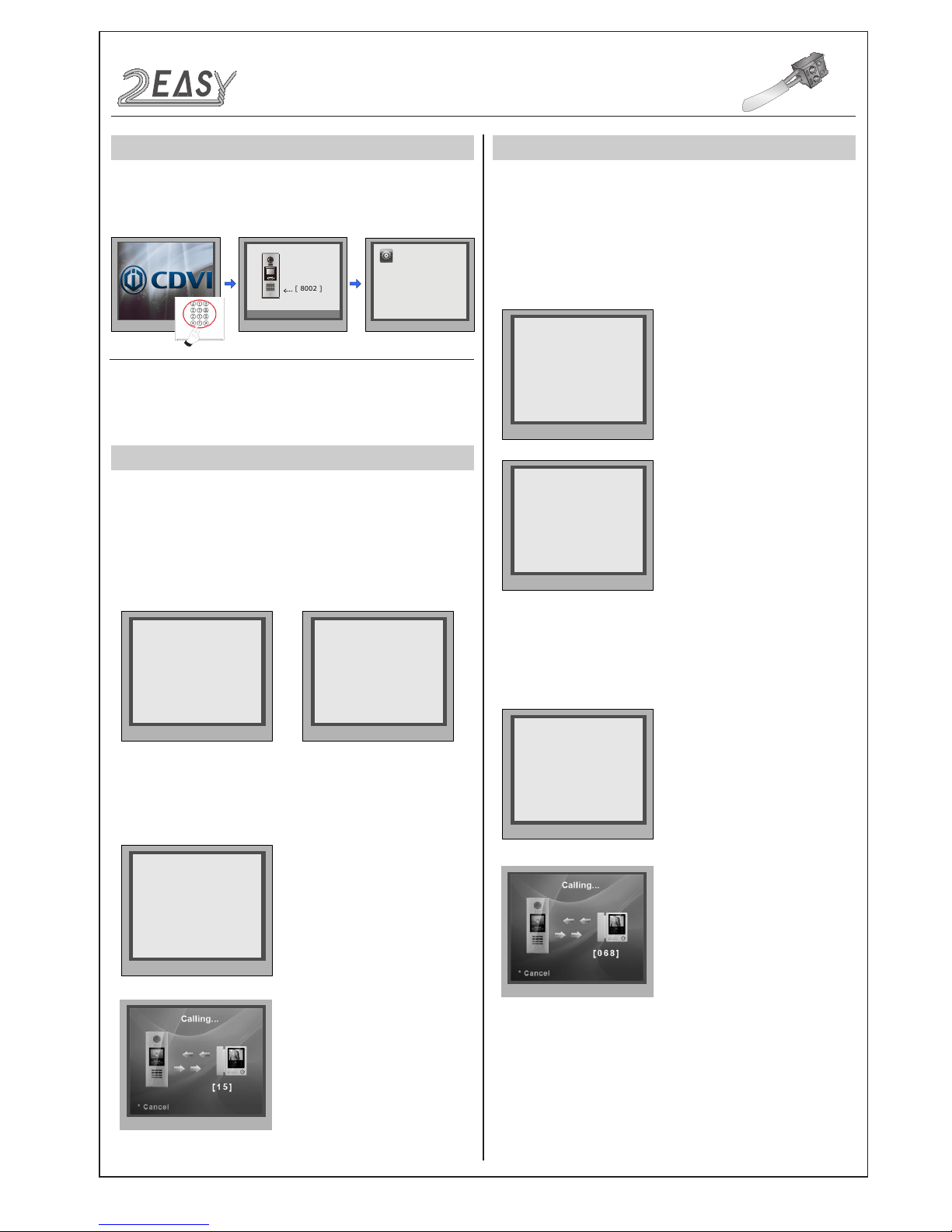
• Select 2 to 'Delete By Card'
• Select 3 to 'Delete By M.code'
3.Card Information:
Select 4 to en ter the
Card
Information page, card count will be showed.
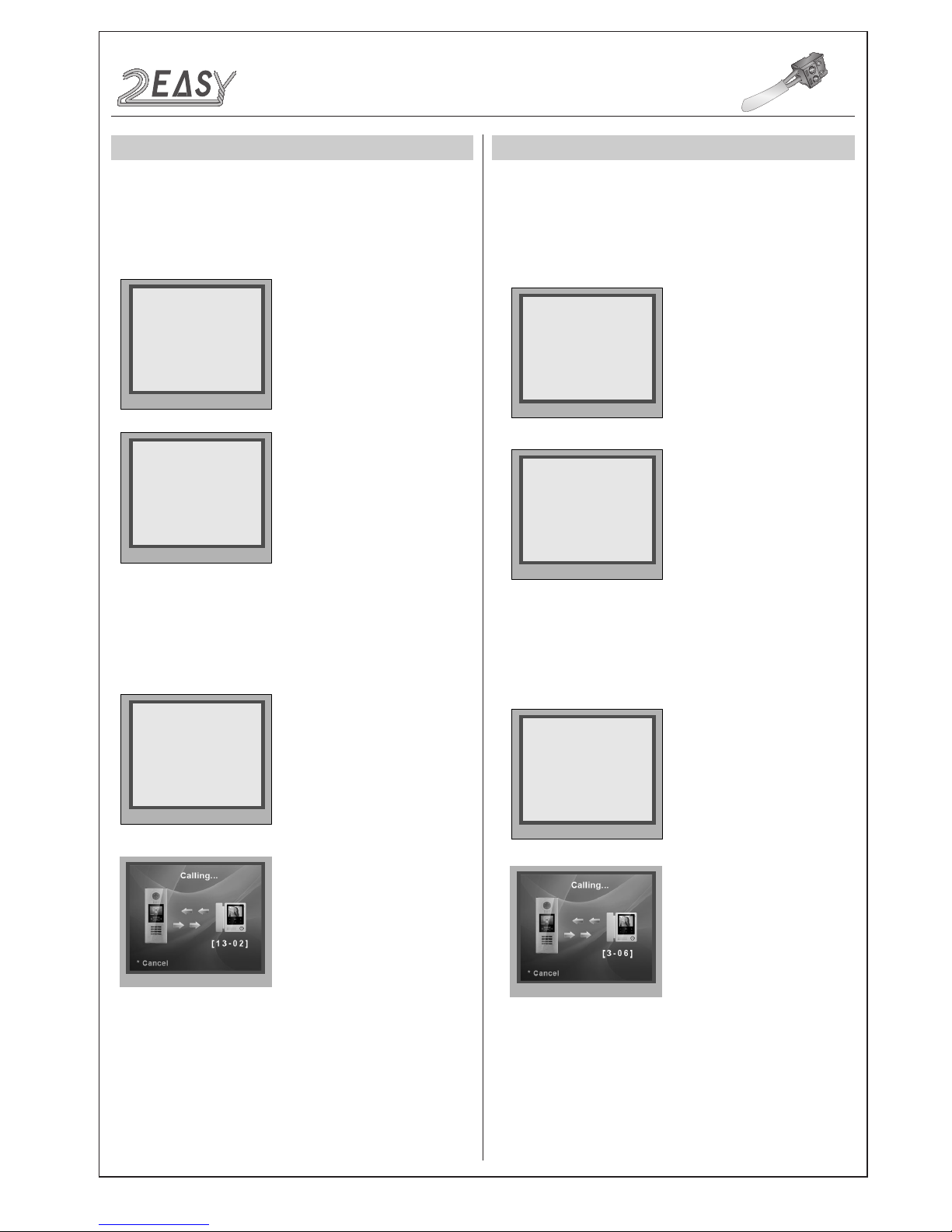
4.Format:
Select 5 to enter the
Format
page. Enter the 8 digit
pass
word to start format.
-8- DMR18S Technical Menu
Page 10
2 EASY
Work Mode
set to 0;
Work Mode set to 0, and ID code set to
0~3.
Work Mode
set to 1:
Work Mode set to 1, and ID code set to
0~3.
DEFINITION
STANDARD 32 APARTMENTS
DT-DJ MODE
* Cancel # Save
(0~3)
[ 0 ]
5. Work Mode [0]
* Cancel # Save
(0~3)
[ 1 ]
5. Work Mode [0]
* Cancel # Save
[ * * * * * *1 1 ]
5. Doorplate Mode [11]
0: *
1: 123
2: ABC
3: -
* Cancel # Save
[ * * * * * 1 1 1 ]
5. Doorplate Mode [111]
0: *
1: 123
2: ABC
3: -
* Cancel # Save
(0~3)
[ 0 ]
1. ID Code [0]
* Cancel # Save
(0~3)
[ 0 ]
1. ID Code [0]
[ 8002 ]
Please Input Password
1 2 3
654
7 8 9
#0
*
RF CARD
Press No.
to select
*Back
Setup
1. Language [0]
2. Tone Select [01]
3. Tone Volume [3]
4. Unlock Code [1111]
5. Work Mode [0]
6. Clock ...
7. Setup Code ...
8. About ...
9. Default ...
CONFIGURATION
Work Mode
When the door station
is in standby, press the
'#' key
Enter '8002', then enter the
Admin Code.(66666666
by default)
Select “5” to enter
Work Mode page.
The
Standard Mode
is used in a small capacity system, under 32
monitors and without a BDU unit. Generally dial 01~32 to call the
monitor.
Input Mode Setting:
In standby mode. Enter #8001+
Code(66666666 by
default), then select “ 5 ” to set the
Doorplate
Mode
, for example enter the code 15 to call the monitor.
Input Mode
: In standby mode. Enter #8001+ Code ( 66666666 by
default), then select “ 5 ” to set the
Doorplate Mode
, for example
enter the code 068 to call the monitor.
The
DT-DJ Mode
is used for the audio intercom system. When the
system contains audio handsets, such as DJ4A, DJ5A, DJ6A, etc.
The
DT-DJ Mode
can be assigned addresses from 001 to 128
without a BDU unit.
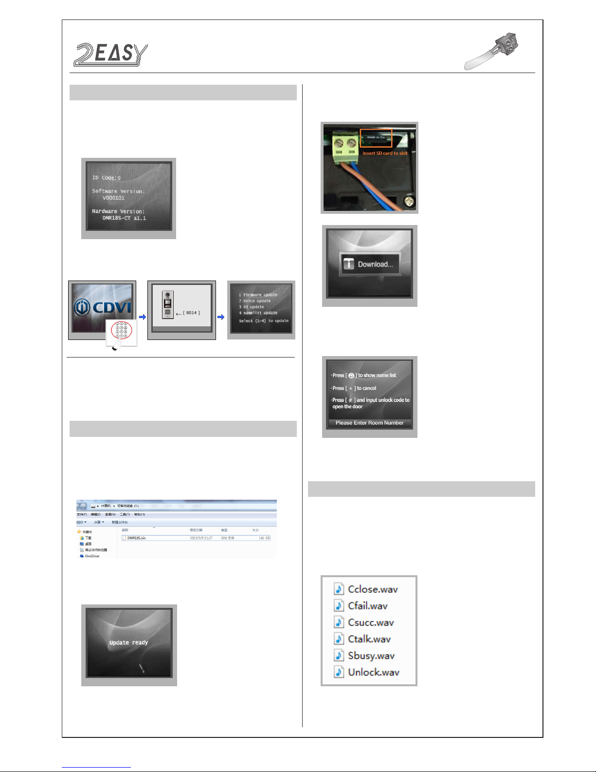
There are four different work modes available for CDV-DDP to
accommodate different situations. In standby mode, enter #8002
+ code (66666666) and select “ 5 ” item to enter
Work Mode
setting
page.
DMR18S Technical Menu -9-
Page 11
2 EASY
Work Mode Set to 2, and ID code set to
0~3
.
Work Mode set to 3, and ID code set to
0~3
.
DT-BDU ROUTER MODE
DT-BDU GATEWAY MODE
* Cancel # Save
(0~3)
[ 2 ]
5. Work Mode [0]
* Cancel # Save
[ * * * 1 1 - 1 1 ]
5. Doorplate Mode [11]
0: *
1: 123
2: ABC
3: -
* Cancel # Save
(0~3)
[ 0 ]
1. ID Code [0]
* Cancel # Save
(0~3)
[ 3 ]
5. Work Mode [0]
* Cancel # Save
[ * * * * 1 - 1 1 ]
5. Doorplate Mode [11]
0: *
1: 123
2: ABC
3: -
* Cancel # Save
(0~3)
[ 0 ]
1. ID Code [0]
Input Mode
: In standby mode enter #8001+ Code ( 66666666 by
default), then select “ 5 ” to set the
Doorplate Mode
, for example
enter 13-02 to call the monitor. As the following picture shows: 13
corresponds to the 13th oor, and 02 corresponds to the second room
number.
Gateway Mode
is used for a community network system, a common
door station is connected into the system which can call all the
monitors, the other door stations connected at each block can only call
the monitors in that block.
Input Mode
: In standby mode. Enter #8001+ Code ( 66666666 by
default), then select “ 5 ” to set the
Doorplate Mode
, for example
enter 3-06 to call the monitor. As the following picture shows: 3
corresponds to the third BDU, and 06 corresponds to the ID code of
monitor.
CONFIGURATION
Work Mode
Router Mode
is used for large capacity systems in conjunction with a
BDU unit. The namelist can be updated by SD Card or CDV-Cong
software (More details refer to
Update Namelist
Section
).
-10- DMR18S Technical Menu
Page 12
2 EASY
DESCRIPTIONS
SOFTWARE UPDATE
TONE UPDATE
1. Format SD card
[ 8014 ]
Please Input Password
1 2 3
654
7 8 9
#0
*
RF CARD
1. Format SD card
2. About the Ringtone le
• English is the standard audio le, as the picture shows:
CONFIGURATION
System Update
How to enter the update page:
When door station is in
standby, press '#' key
Enter '8014', followed by
the Code 87625761
Update page overview
2. Copy the update software file (DMR18S.bin, provided by our
company) to SD card by computer.
6. When the update is nished, it will return to
Standby Mode
interface.
4. Select 1 to enter
Firmware update
, the screen will show
“update ready”.
5. Insert the SD card into the slot shown below, “Download...” will
be displayed when the updated is in progress. After 3 seconds, a
long sound “BEEP” will be heard to start the update.
This section covers for software version V000101/2 for the
CDV-DDP. (After 2015.07.10). In standby mode, enter “#+#” to
check the CDV-DDP software version, see the following picture:
DMR18S Technical Menu -11-
Page 13
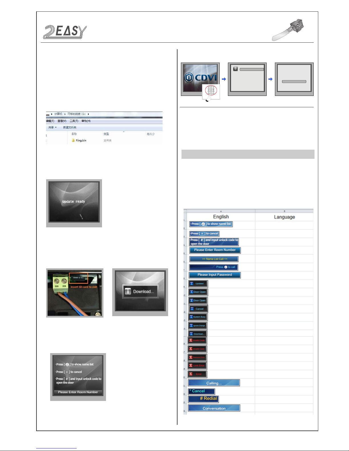
2 EASY
6. When update is nished, it will return to
Standby Mode
interface.
UI UPDATE
When door station
is in standby, press
'#8002'+code 66666666
to enter
Setup
page.
Tone Select
setting
page.
* Cancel # Save
2. Tone Select [01]
00 Mute
01 Tune
Press No.
to select
*Back
Setup
1. Language [0]
2. Tone Select [01]
3. Tone Volume [3]
4. Unlock Code [1111]
5. Work Mode [0]
6. Clock ...
7. Setup Code ...
8. About ...
9. Default ...
02 English
3. Copy the Ring.bin le to SD card by computer.
7. Check the Tone
Select 02(English) to
check your tone update,
and press # to save.
1. Format SD card
2. Edit UI le
CONFIGURATION
System Update
• If other languages are required, please record the audio le in the
language required.
• Then send the audio le to our company, a Ring.bin le will be
created for you to update the tone.
select 2 to enter
4. Select 2 (Voice update) to enter
Tone update
, the screen will
show 'Update Ready'
5. Insert the SD card into the slot shown below, “Download...” will be
displayed when the updated is in progress. After 3 seconds, a
long sound “BEEP” will be heard to start the update.
Multiple languages are supported on the CDV-DDP, English is the
default language, if other languages are required, please provide the
translation to us. About the UI le, see the following picture shows:
-12- DMR18S Technical Menu
Page 14
2 EASY
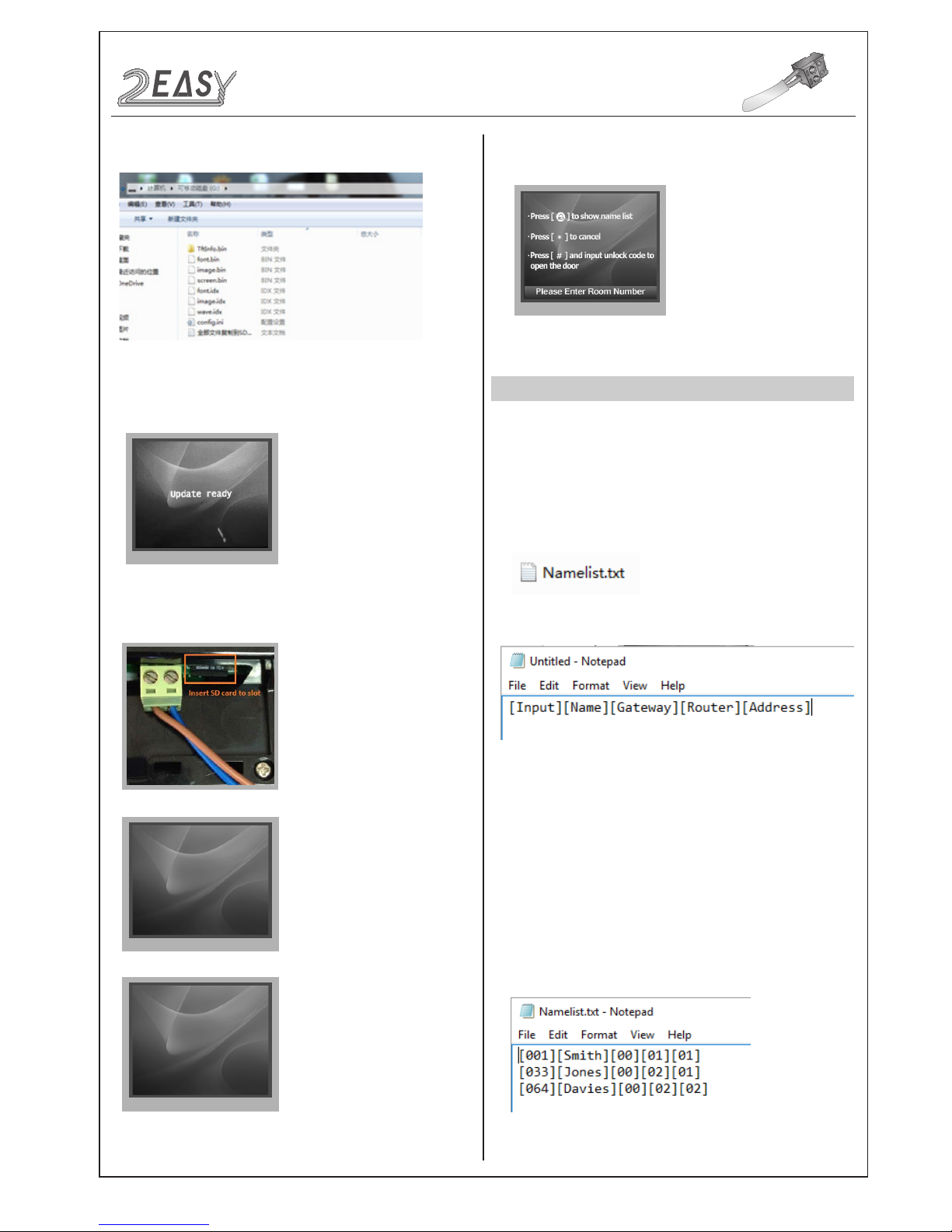
3. Copy the Update UI le to SD card by computer.
font.bin :12%
font.bin :100%
image.idx :100%
image.bin :6%
NAMELIST UPDATE
1) Namelist update by SD card
1. Format SD card
2. Namelist.txt le setting
• Open the NameList.txt file, and input 5 [ ] symbols. Each [ ]
symbol has its meaning, see the following picture.
Descriptions:
• Edit NameList.txt le, for example, as the following picture shows:
CONFIGURATION
System Update
6. When update is nished, it will return to
Standby Mode
display.
And show the new UI.
• Create a TXT le, named NameList.
Input:
Enter the number to call the monitor
Name:
As it would be displayed on screen
Gateway:
Set the gateway mode according to the BDU
address.
[08~15] means BDU address 01~08
Router:
Set the Router mode according to BDU address. [01~08]
means BDU address 01~08
Address:
Set the monitor address required
Enter101 or 1-01, it would call the monitor 01 in BDU 1.
4. Select 3 to enter
UI update, the screen will show 'Update Ready'.
5. Insert SD card to slot, after that, the update progress will be
shown.
DMR18S Technical Menu -13-
Page 15
2 EASY
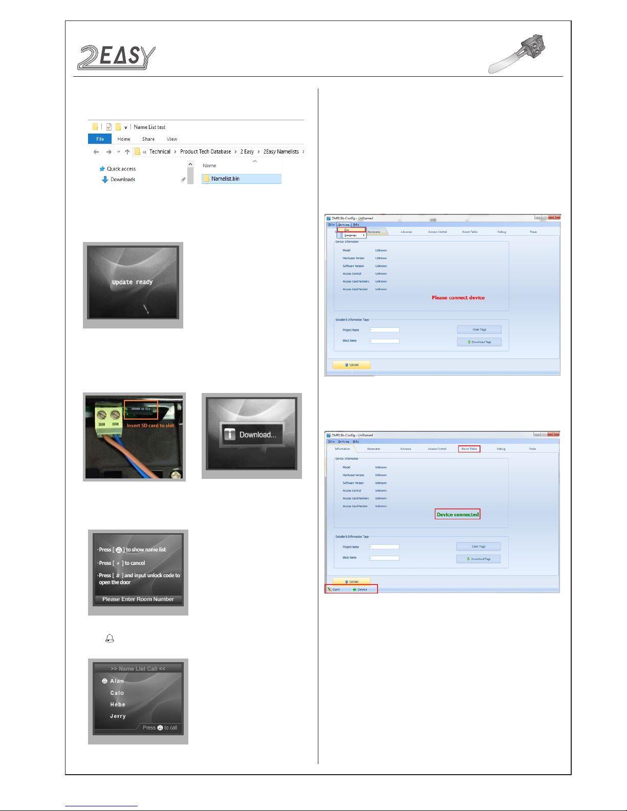
3. Copy the Namelist le to SD card by computer.
7. Press touch button to show the Name list
3. Then click “Insert” to create the rst item.
Address:
Monitor’s address (can be nd in “about”);
Name:
The name of resident;
CONFIGURATION
System Update
4. Select 4 to enter
Namelist update
,the screen will show
'Update Ready'.
5. Insert the SD card into the slot shown below, “Download...” will
be displayed when the updated is in progress. After 3 seconds,
a long sound “BEEP” will be heard to start the update.
6. When update is nished, it will return to
Standby Mode.
CDV-Cong software is to enable parameter setting of the
CDV-DDP, i.e. namelist setting etc.
The CDV-Cong software operation is as follows:
1. Open the “CDV-Config” software, connnect the CDV-DDP to
a PC via USB-RS-485; Click “Setting” on the menu bar, then click
Com to select the correct Com port.(Com port information can be
found in “ My Computer -> Properties ->Device Manage->Ports”)
2. Then if the CDV-DDP is connected to a PC successfully, “Device
connected” will be shown. Click “Room Table” tab to edit Name list.)
Each item has 5 different properties:
User Code:
The number used to call the monitor;
Router:
Sets the BDU address when in Router mode;
Gateway:
Sets the BDU address when in Gateway Mode.
2) Namelist update by CDV-Cong
-14- DMR18S Technical Menu
Page 16
2 EASY
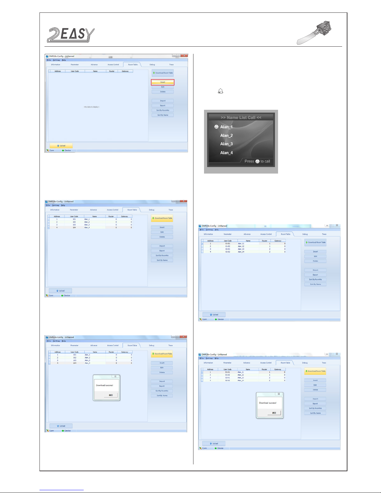
4. Edit Namelist
4.1 Apartments
• For example: Dial 101 to call the Apartment 01 without BDU. See
• Click Download Room Table to download the namelist.
CONFIGURATION
System Update
the following picture:
• After editing, click “Download Table” to download Name List to
the CDV-DDP; After a few seconds, a window will be displayed
if it is updated successfully.
• Check Name List on CDV-DDP
Set the CDV-DDP
Work Mode
to 0 (for more details refer to
Work
Mode
setting section).
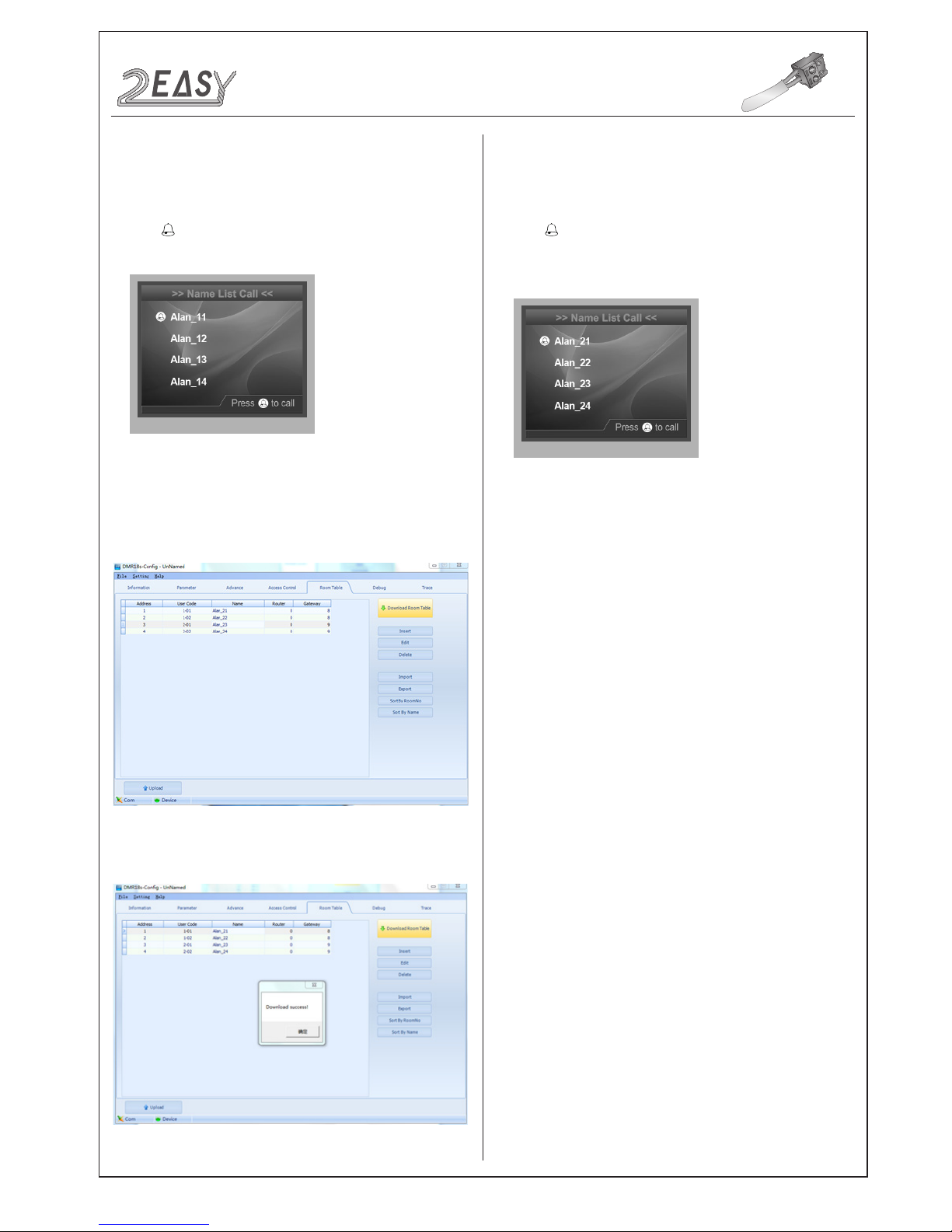
• Press touch button to enter
Name List
page. See the following
picture.
4.2 Router
• Enter 01-01 to call the monitor 01 connected to BDU 1 when
the system is in Router Mode, Ex. enter 02-02 to call monitor
connected to BDU 2, see the following picture.
DMR18S Technical Menu -15-
Page 17
2 EASY
4.3 Gateway
• Click Download Room Table to download the namelist.
CONFIGURATIONS
System Update
• Check Name List on CDV-DDP
• Press touch button to enter
Name List
page. See the following
picture.
• Input 1-01 to call the monitor 01 connected to BDU 1 when
the system is in Gateway
mode, EX. enter 2-02 to call the
monitor 02 connected to
BDU 2, see the following picture:
Set the CDV-DDP to
Work Mode
2 (more details refer to
Work Mode
setting section).
Set the CDV-DDP to
Work Mode
3 (more details refer to
Work
Mode
setting section).
• Press touch button to enter
Name List
page. See the following
picture.
• Check Name List on CDV-DDP
-16- DMR18S Technical Menu
 Loading...