

Page 1
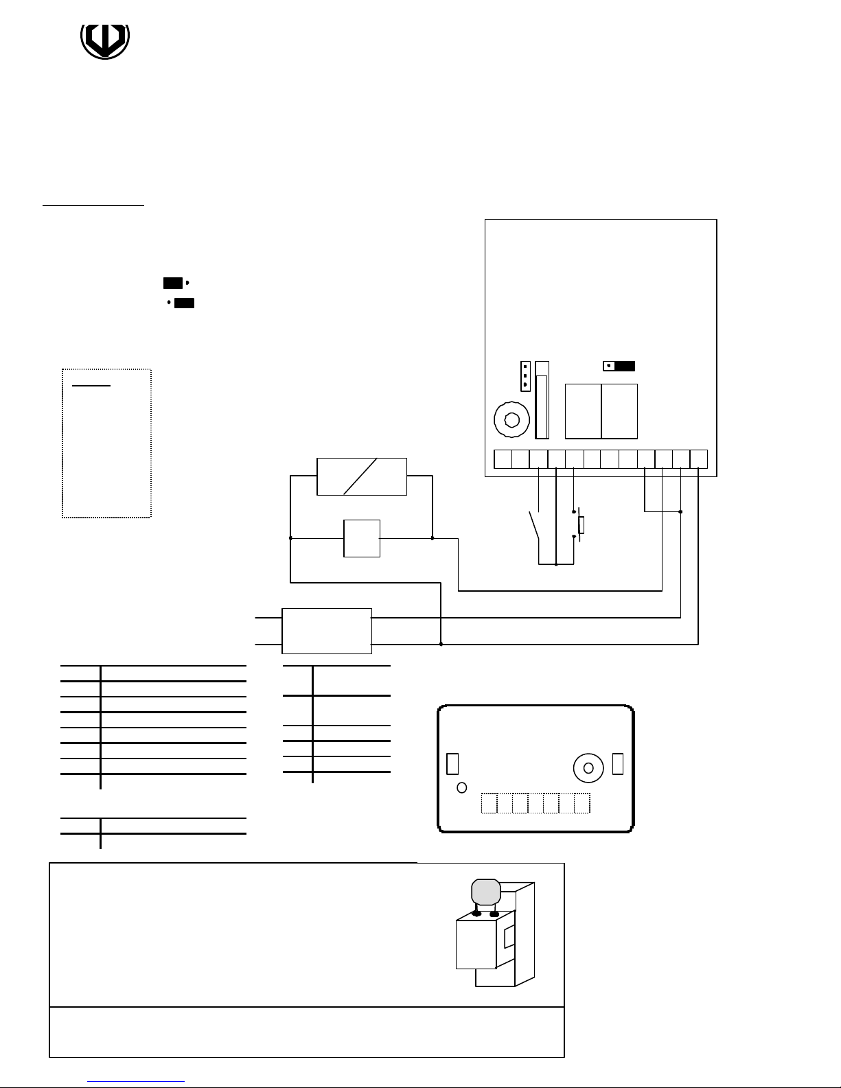
Wiring diagram
PCB front view
back emf.
ST1
(terminal connections)
Warning
Do not use a
switching
power supply
because of the
interference
radiation that
may disturb
the reading of
the badges
ST2
1
1 3
STAND-ALONE PROXIMITY SYSTEM
N/C contact RL1 (magnet)
3
N/O contact RL1 (strike)
DGPROX
PIN Code and/or Badge
ST1 ST2
3
2
1
strike
I1
1 3
RL1RL2
32 V1 E M B OCT5 12
V1
Input voltage
12V ~ or =
12 Power
supply
V Po
wer supply
1 Data
2 Buzzer
3 Green LED
B Request-to-exit PB1
E Alarm Input
M Common PB1, E and 4
O Relay 1 contact
C Common
T Relay 2 N/O contact
I1 Anti-tamper switch
V1 Varistor
Jumper for reset
ST2
Jumper for relay 1
RL1 Door relay
RL2 Alarm relay
230V~
This device comes with a varistor.
The varistor must be connected on the strike terminal
(electromagnet…) operated by the device.
If this product operates more than one strikes, each of them
should have a varistor.
The varistor controls the overload produced by the strike coil –
PB1
Auxiliary reader
12 V 1 4 5 3 2
See wiring diagram auxiliary reader
If you are using a « Shear Lock » electromagnetic lock, it is recommended to use a
separate power supply than the one connected to the DGPROX.
Page 2
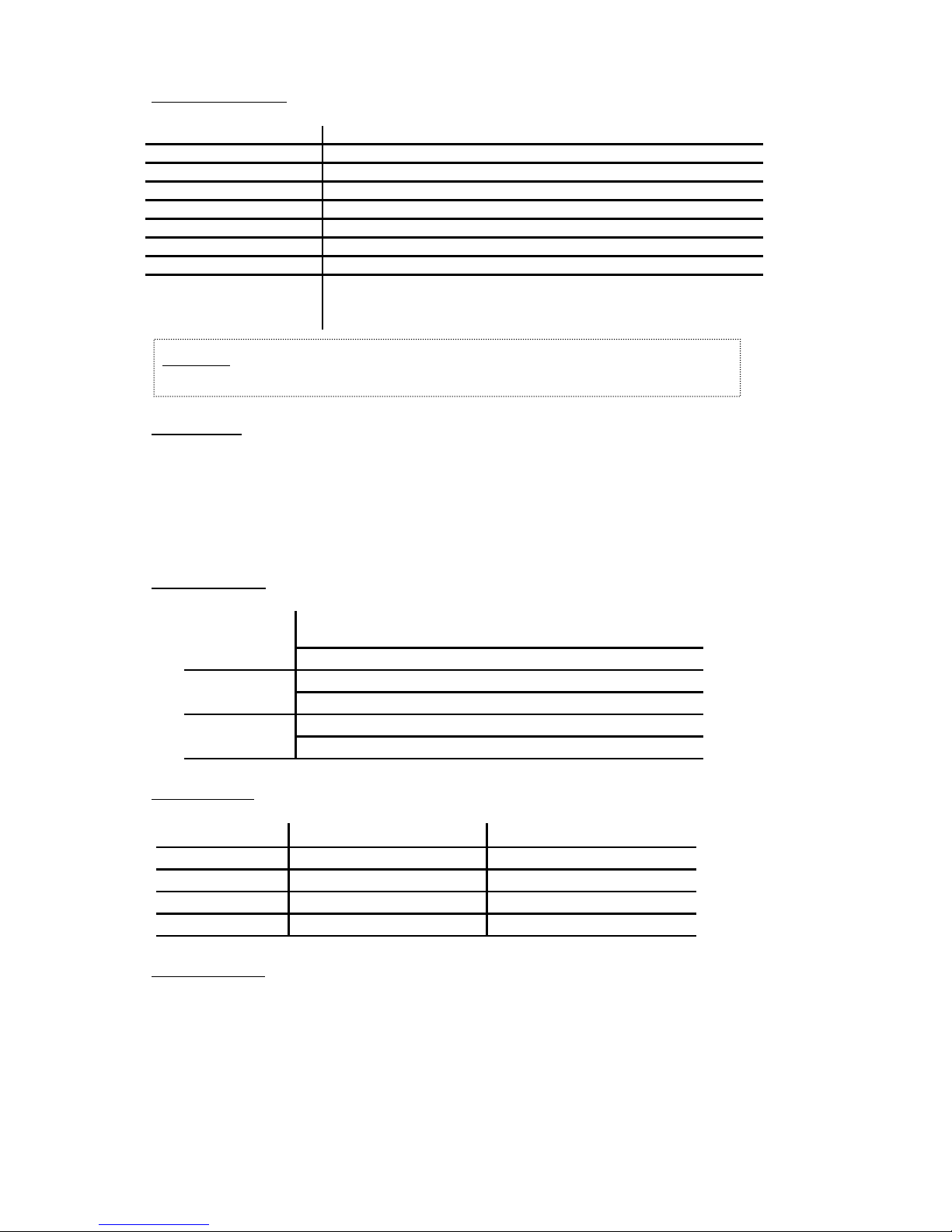
Technical features
Warning: Do not use a switching power supply because of radiation
Input voltage 12 VAC/DC
Output 2 relays, N/O & N/C contact 3A /125V
Anti-triggering contact 500 mA 50 V ~ or =
Badge entry 500 programmable badges
Code entry 500 programmable codes, 5-digit PIN code
Master code 5-digit programmable code
Input 1 request-to-exit
Keyboard 12-digit keypad with built-in buzzer (audible signal)
Distance between the
second reader and the
DGPROX unit
minimum 24 inches (60 cm)
maximum 45 yards (50 meters)
(cable minimum 7 x 0.6 mm
2
AWG22)
interference, which may disturb the reading of the badges.
Default values
Master code: 12345
Relay time delay: 1 second
Key-in keypad: 10 seconds
Alarm: Off
Audible signals
1 beep (long) Validation of data in programming mode: master code,
proximity badge or time delay.
Or access code validated
2 beeps (short) Accessing the programming mode
or exiting from the programming mode
4 beeps (short) incorrect mode, user number time delays entered
Visual signals
LED color Normal mode Programming mode
Green Door relay activated Code/Badge position empty
Red Alarm relay activated Code/Badge position busy
Orange Programming mode
Orange flashing Stand-by Data computing error
Request-to-exit
The request-to-exit push button PB1 operates relay RL1.
The LED turns green when the relay is activated.
2
Page 3

Setting a new master code
Enter the master code twice (for the first use, the master code default is 12345). 2 beeps will sound and the orange
LED illuminates to confirm that you are in programming mode.
Enter *3 then 5-digit for the new master code. The LED goes out for 1 second and an audible beep indicates that the
new master code is accepted.
Press # to exit from the programming mode. 2 beeps confirm that the reader is in standby mode.
4 beeps indicate a data computing error.
Setting operating mode and relay outputs
Enter the master code twice (for the first use, the master code default is 12345).
2 audible beeps, and the orange LED illuminates to confirm entry into programming mode.
Operating mode
Door relay
Alarm Relay
Press # to exit from the programming mode. 2 beeps confirm that the reader is in standby mode.
4 beeps indicate a data computing error.
Enter Ý0 then the 2-digit of the operating mode
00: PIN code and proximity badge, up to 500 users (500 PIN +
500 badges)
01: Proximity badges only up to 500 users.
02: PIN codes or proximity badges, up to 500 users.
The LED goes out for 1 second and an audible beep indicates
the time delay has been accepted.
Enter Ý1, then the time in seconds:
01 equal 1 second up to 99 for 99 seconds.
00 sets a latched output (toggle on/toggle off)
The LED goes out for 1 second and an audible beep indicates
the time delay has been accepted.
Enter Ý2, then the time in seconds:
01 equal 10 seconds up to 99 for 990 seconds.
00 to turn the alarm off
The LED goes out for 1 second and an audible beep indicates
the time delay has been accepted.
Setting new user codes and proximity badges
Enter the master code twice (for the first use, the master code default is 12345).
2 audible beeps, and the orange LED illuminates to confirm entry into programming mode.
Enter the user number (000 to 499). If the LED is green, the user number is available, therefore present a badge in
front of the main reader. Once the audible beep will sound and the green LED will change to orange then enter a 5digit code a long beep will sound to confirm that the badge and code has been accepted. If the LED is red the user
number is unavailable, therefore press the * key twice to cancel the old badge/code. Enter another user number or
press # to exit from the programming mode. 2 beeps confirm that you have returned to standby mode.
3
Page 4

Canceling or replacing programmed user codes and badges
Enter the master code twice (for the first use the master code default value is 12345). 2 beeps and the orange LED
light on to confirm that you have entered into the programming mode.
Enter the user number (000 to 499). The LED lights off during 1 second and an audible beep is emitted.
The red LED lights on indicating that the user number is unavailable.
Press the * key twice (**). The LED lights off during 1second and an audible beep is emitted.
The green LED lights on indicating that the user badge/code is cancelled, the user number is now empty.
Press # to exit from the programming mode.
OR
Present the new badge in front of the main reader. Once the audible beep will sound and the green LED will change
to orange then enter a 4-digit code a long beep will sound to confirm that the badge/code has been memorized.
To exit from the programming mode press #. 2 beeps confirm that you have returned to the reading mode.
Reset the master code and the badges
Put the jumper ST1 to position 2-3.
The green LED blinks during 5 seconds. An audible beep confirms that the master code has been
reset to the default value 12345. The red LED blinks.
Take off the jumper from position 2-3 to go back to a normal mode.
OR
Keep the jumper on position 2-3 to reset all the proximity badges.
The red LED blinks during 5 seconds then stays on during the reset.
When the reset is completed the red LED lights off.
Take off the jumper from position 2-3 to go back to a normal mode.
Operating instructions
Mode 00: Present the badge in front of the DGPROX one audible beep will sound to confirm that the badge is valid,
then enter the PIN code.
Mode 01: Present the badge in front of the DGPROX reader or of the second reader.
Mode 02: Present the badge in front of the DGPROX reader, the second reader or enter the PIN code.
After 3 incorrect badge and/or PIN code are entered, the DGPROX reader and the second proximity reader are
locked out during 30 seconds and the alarm relay is activated. 2 audible beeps sound when the badge/PIN code are
not valid.
Alarm function
The tamper switch activates the relay of the alarm when the front panel is removed. If the alarm time delay is
different to 00, the door monitoring (door ajar or door forced open) is enabled:
When the door is opened, without being activated by the request-to-exit button or a badge, the alarm relay is
activated after 1 second and the red LED lights on (forced open door).
When the badge or the request-to-exit button are used to open a door, if the door stays open, the open contact will
trigger the alarm relay according to the door relay output.
Momentary output – the alarm time delay begins at the end of the door time delay. If the door is maintained open
after the alarm time delay, the alarm relay is activated and the red LED lights on. Closing back the door will
deactivate the alarm relay and the LED lights off.
Latched output – the alarm time delay begins only when the door stays open after ordering the closing by presenting
back the badge or pressing on the request-to-exit button, the alarm relay is activated and the red LED lights on.
Closing back the door will deactivate the alarm relay and the LED lights off.
User badges list (Make other copies if needed) :
4
Page 5
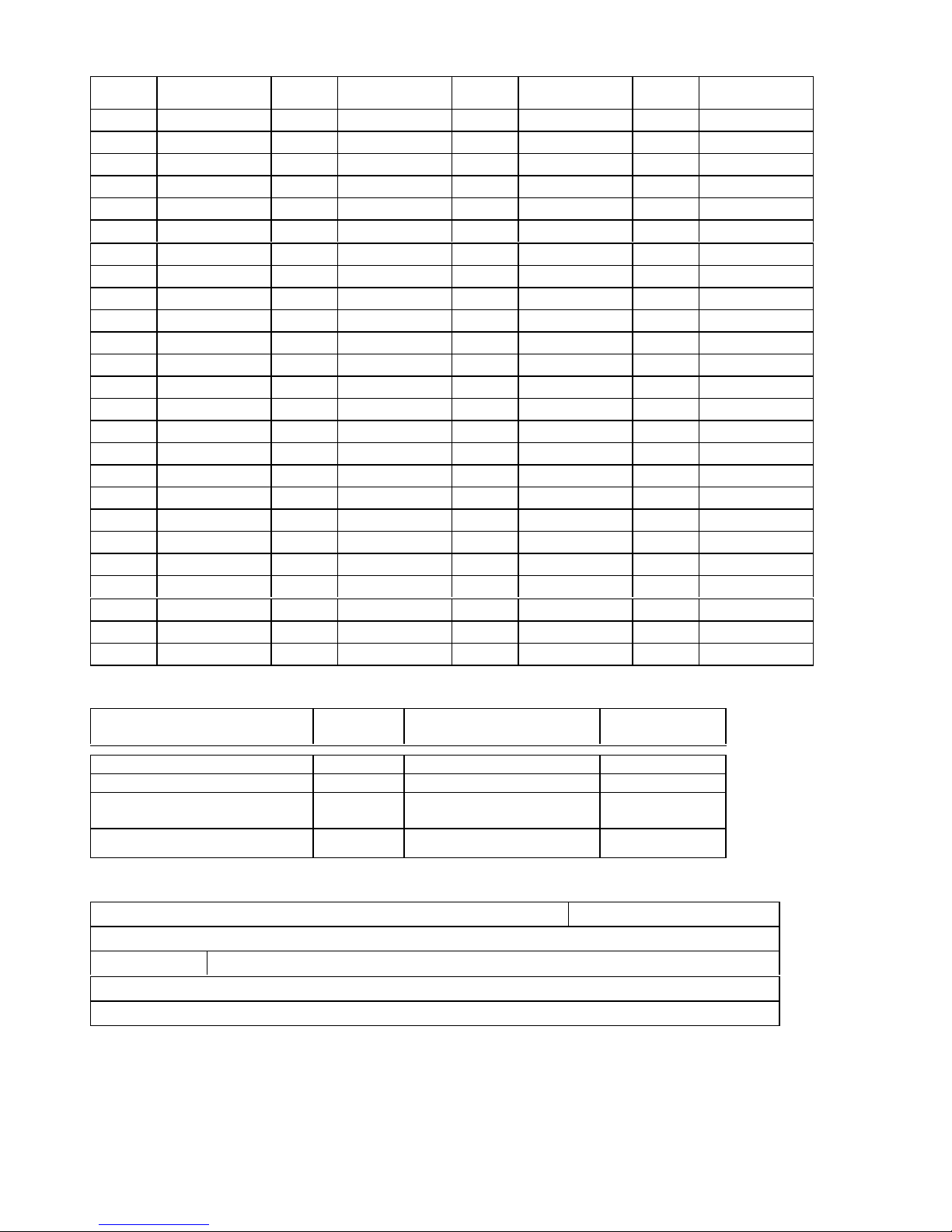
User
number
Name User
number
Name User
Number
Name User
number
Name
Time delays Function n° Values Programmed
Keypad key-in delay * 0 10 = 10 sec, 99 = 99 sec
Door relay * 1 01 = 1 sec, 99 = 99 sec
« opened door » before alarm * 2
Master code * 3
00 = without alarm
01 = 10 sec, 99 = 990 sec
5-digit code
Supervisor : Date
Building :
N° : Street :
City :
Other information :
values
5
Page 6
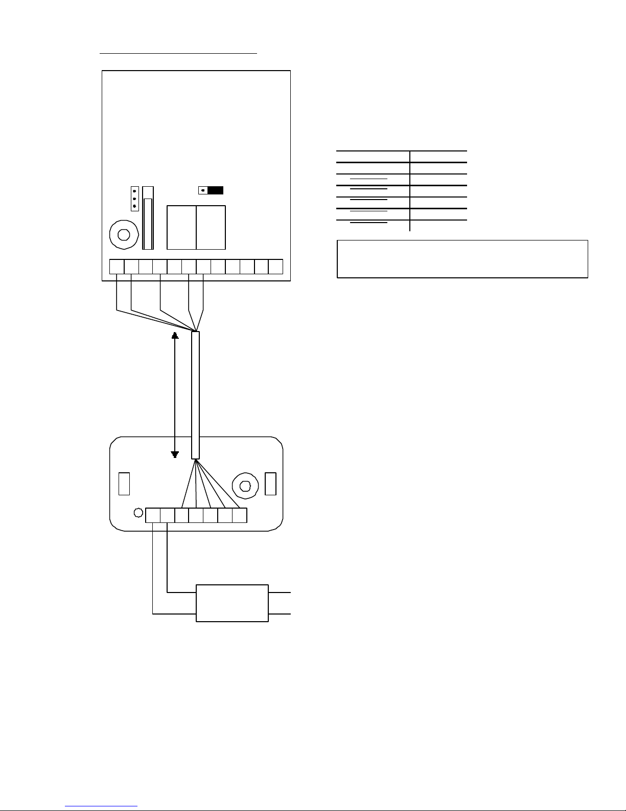
Wiring diagram auxiliary reader
12
Power supply
Power supply
ST1 ST2
I1
3
2
1
Distance :
minimum 60cm
maximum 50 m
1 3
RL1RL2
32 V1 E M B OCT5 12
Auxiliary reader
(terminal connections)
DGPROX
V
1 1 Data
2 2 Buzzer
3 3 Green LED
M 4 Common
5 5 Red LED
Reader
It is recommended to use a separate power supply for the
auxiliary reader.
Input voltage
3 2V 1 4 512
12V ~ or =
230V~
6
Page 7
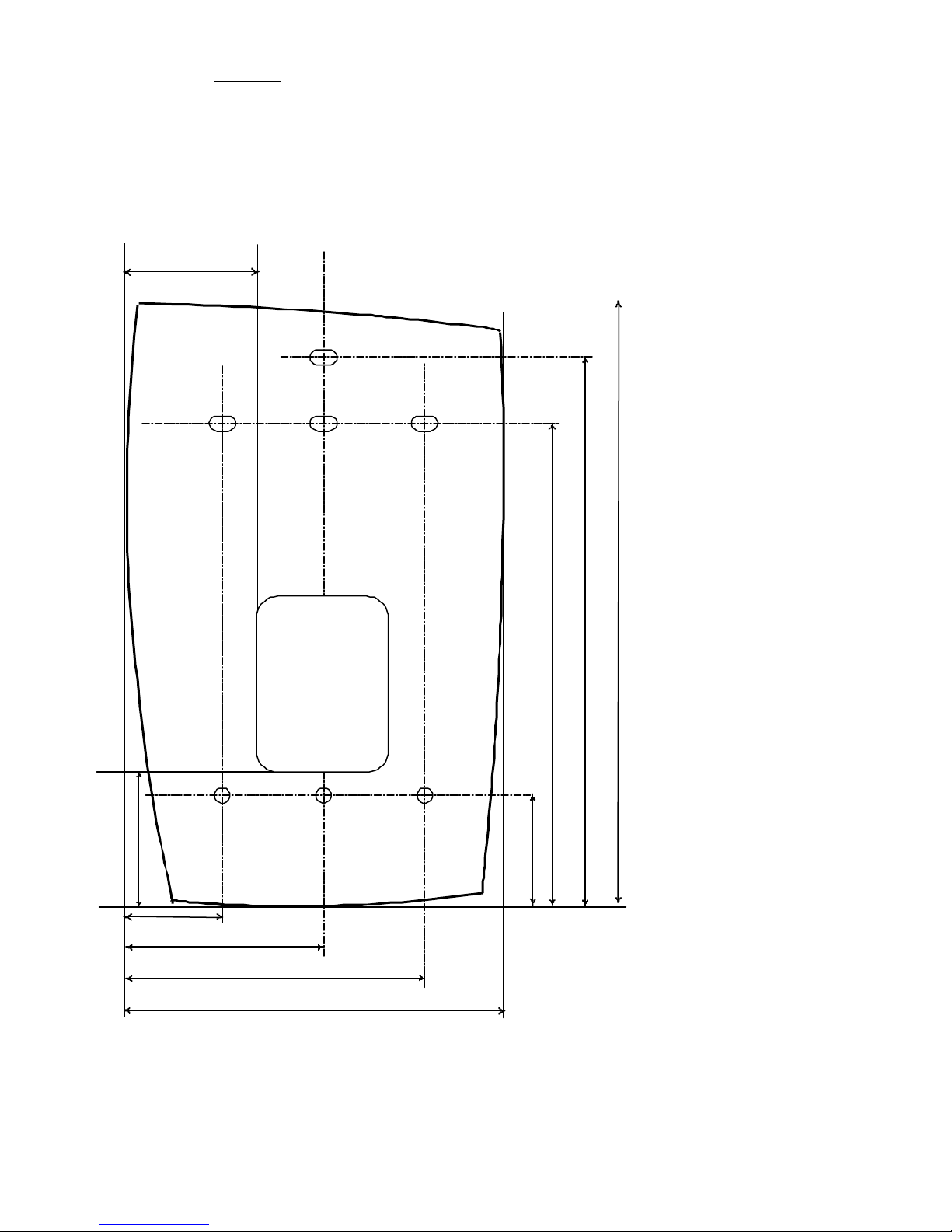
Template
29 mm
68 mm
86 mm
• DGPROX
31 mm
22 mm
Wiring Access
Area
30 x 40 mm
45 mm
137 mm
125 mm
110 mm
26 mm
7
Page 8

8
Page 9
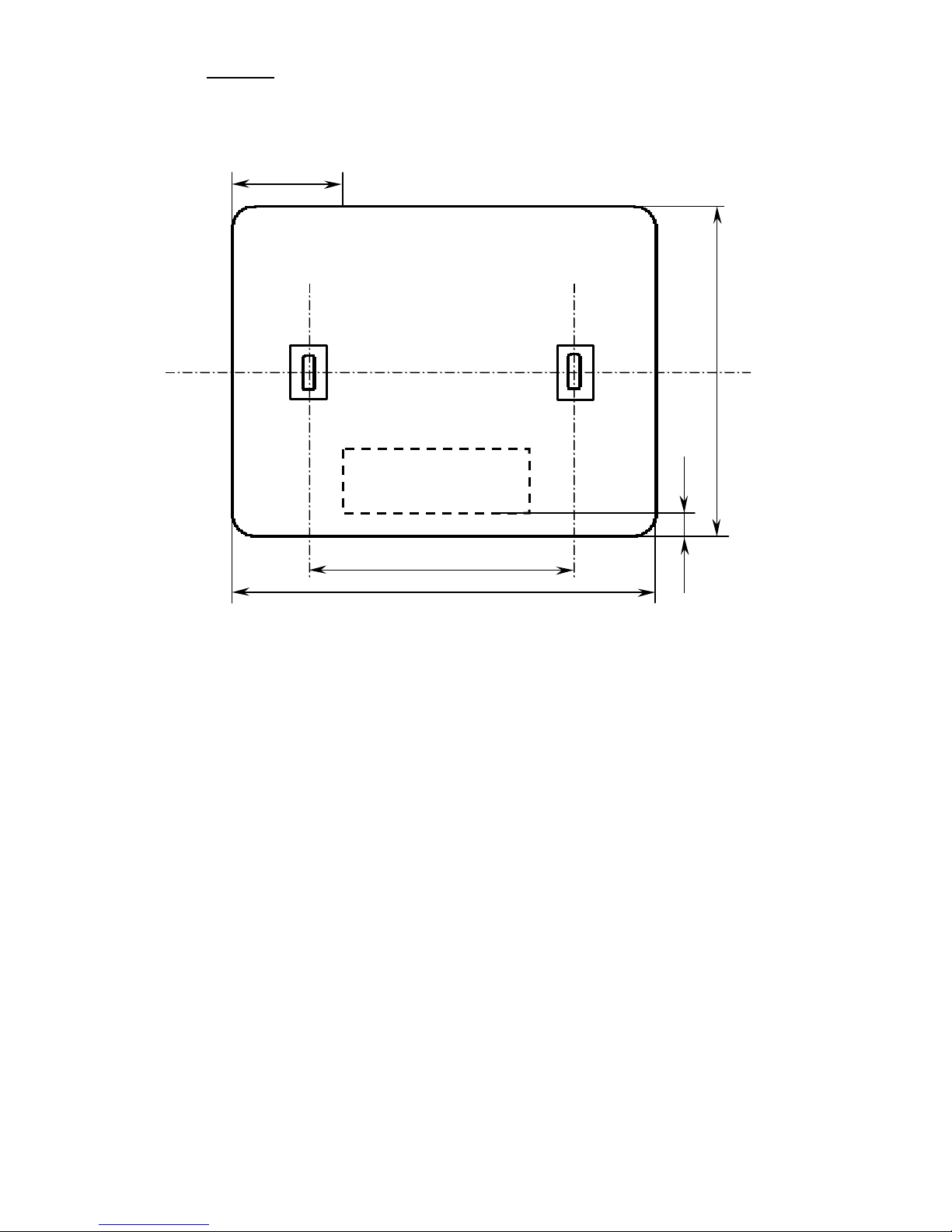
Template
43x15 mm
60
96
25 mm
• DGLI and DGLP Auxiliary reader
]
Block terminal
75 mm
6 mm
FCC statement:
NOTE: This equipment has been tested and found to comply with the limits for a
Class B digital device, pursuant to Part 15 of the FCC Rules. These limits are
designed to provide reasonable protection against harmful interference in a
residential installation. This equipment generates, uses and can radiate radio
frequency energy and, if not installed and used in accordance with the
instructions, may cause harmful interference to radio communications. However,
there is no guarantee that interference will not occur in a particular installation.
If this equipment does cause harmful interference to radio or television reception,
which can be determined by turning the equipment off and on, the user is
encouraged to try to correct the interference by one or more of the following
measures:
-- Reorient or relocate the receiving antenna.
-- Increase the separation between the equipment and receiver.
-- Connect the equipment into an outlet on a circuit different
from that to which the receiver is connected.
-- Consult the dealer or an experienced radio/TV technician for help.
Caution:
Changes or modifications not expressly approved by C.D.V.I. could void the user's
authority to operate the equipment.
9
 Loading...