

Page 1

DGLPWLC
DGLPFNWLC
DGLIWLC
DGLIFWLC
Group Products
MANUEL D’INSTALLATION
Lecteurs Proximité intérieur/extérieur - Wiegand
Gamme: Contrôle d’Accès centralisé
INSTALLATION MANUAL
Indoor/Outdoor Proximity Card Readers - Wiegand
Range: Integrated Access Control /
FRANCAIS
FR
ENGLISH
EN
Page 2

DGLIWLC
DGLPFNWLC
DGLPWLC
DGLIFWLC
2
cdvi.com
cdvigroup.com
EN
DGLPWLC - DGLPFNWLC - DGLIWLC - DGLIFWLC
Proximity Card Readers - Wiegand Output
1] PRODUCTS OVERVIEW
2] RECOMMANDATIONS
3] MOUNTING KIT
Important
To protect the device from back - emf
do not forget to mount the varistor
on the lock in parallel.
Recommended cables
4 twisted pairs 0.6 MM.
Optional
Single gang box mounting plate
for the DGLPFNWLC reader
(Ref: MPLATE).
Environment
When in a humid area or close to
a sea shore, we recommend applying a varnish on the terminals
to avoid oxidation.
Suggested power supplies
ARD12 & BS60
INSTALLATION MANUAL
HIGH RESISTANCE
TO VANDALISM
IP53
-25°C to +70°C
CE Certifi cation
WEEE
Certifi cation FCC CFR 47
part 15 compliance
Varistor
Diax
®
spanner
Diax
®
screw
stainless steel
Brass
anchor
Right cover Left cover
Plastic
anchor
Wood screw
3 x 40 mm
DGLIWLC 1 1 2 2 - - - -
DGLPWLC 1 - - - 2 2 2 2
DGLIFWLC 1 1 2 2 - - - -
DGLPFNWLC 1 - - - 2 2 2 2
Wiegand 26,30 or 44 bits.
Direct connection to the controller
or with the door controller (INTBUSW).
PCB sealed in epoxy.
Audible and visual feedback.
Available in version:
- Polycarbonate standard “VO” (DGLPWLC).
- Stainless steel (DGLIWLC).
DGLPWLC (L x W x D): 103 x 81 x 23mm.
DGLPFNWLC (L x W x D): 139 x 41 x 23mm.
Technology: 125 kHz*.
Multi card protocol reader.
Input voltage: 12V dc.
Consumption: 100mA.
* Complies with European R&TTE directive 99/5/EC and harmonised
standards: ETS 301 489 and ETS
300-330-1-Ed 2001. Complies with
applicable EMC standards:
EN 50133, EN 50130-4.
Page 3

31 2 4
ON
OFF/OFF
26 bits
ON
Centaur Mode
OFF
Pull up 5V
ON/OFF
30 bits
OFF
CDVI Mode
ON
Pull up 12V
OFF/ON
44 bits
ON/ON
Non allocated
DGLPWLC and DGLIWLC
DGLPFNWLC and DGLIFWLC
The buzzer and the LED’s
can be controlled by the
reader or by an external
device.
Pulls up 12 V or 5V
Open collector outputs:
The controller or the audio entry
system can manage the LED
and the buzzer to program
other operations.
In standard, when a card or
a tag is placed within the reader
the orange LED is activated
and the buzzer emit a tone.
The Centaur controller can
manage the LED and the buzzer
to program other operations.
Select the output voltage
according to the installation.
DIPSWITCH 1 & 2
POSITIONNING
DIPSWITCH 3
POSITIONNING
DIPSWITCH 4
POSITIONNING
EN
DGLPWLC - DGLPFNWLC - DGLIWLC - DGLIFWLC
Proximity Card Readers - Wiegand Output
4] WIRING DIAGRAM : DGLPWLC, DGLIWLC, DGLPFNWLC et DGLIFWLC
INSTALLATION MANUAL
3
cdvi.com
cdvigroup.com
Terminal (8 pins)
+ Input voltage 12VDC
- 0V
H Clock
D0 Data 0
D1 Data 1
B Buzzer
V Green LED
R Red LED
Wiring
Red Input voltage 12VDC
Black 0V
Blue Clock
Green Data 0
White Data 1
Brown Buzzer
Yellow Green LED
Orange Red LED
Page 4

4
cdvi.com
cdvigroup.com
DGLPWLC - DGLPFNWLC - DGLIWLC - DGLIFWLC
Proximity Card Readers - Wiegand Output
INSTALLATION MANUAL
6] OUTPUT FORMATS 26, 30 ET 44 BITS WIEGAND
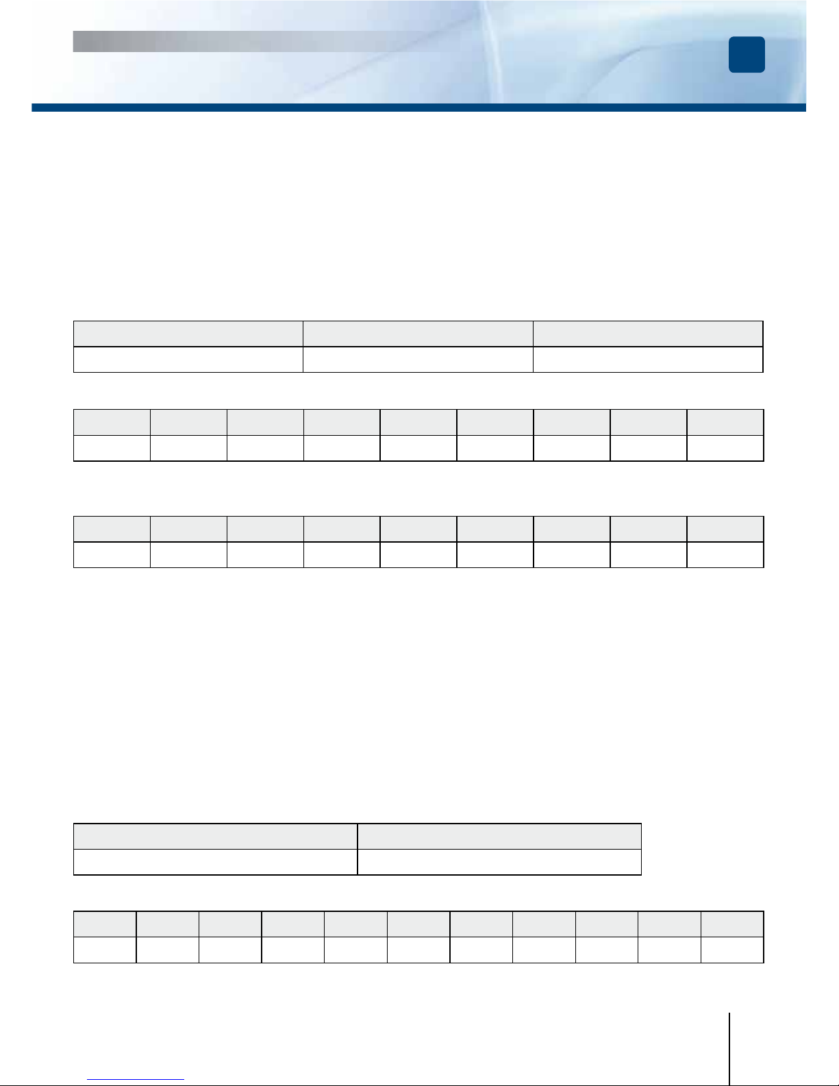
Chronograms
Open collector output with internal pulls up 1K at +5V or +12V according the ST4 position.
26-bit Wiegand Output
Structure and description of the code :
DGLPWLC - DGLPFNWLC - DGLIWLC - DGLIFWLC > Place the ST5 jumper on 1
Format 26-bit hexadecimal. The output format is 26-bit Wiegand (Signals: DATA1, DATA0 and CLOCK)
The frame is made of 26-bit and built as follow:
1 - First parity: 1-bit – even parity for the rst 12-bit
Code of the badge: 6 half byte represent the last 6 digit of the code (4bit = 1 digit of a code)
Each byte is transferred from bit 7 to bit 0.
2 - Second parity: 1-bit – odd parity for the last 12-bit
Bit 1 Bit 2 to bit 25 Bit 26
Even Parity on bit 2 to bit 13 Data (24 bit) Odd Parity on bit 14… bit 25
Example: code of the badge is 0100166A37.
1 0001 0110 0110 1010 0011 0111 0
Parity 1 1 6 6 A 3 7 Parity 2
The code transmitted is in hexadecimal format 166A37
Parity 1: 0 if the number of 1 in bit 2 to bit 13 is even
1 if the number of 1 in bit 2 to bit 13 is odd
Parity 2: 0 if the number of 1 in bit 14 to bit 25 is odd
1 if the number of 1 in bit 14 to bit 25 is even
0 logic
\DATA1
\CLOCK
\DATA0
50 µs 50 µs
2ms 2ms
1 logic
EN
Page 5
DGLPWLC - DGLPFNWLC - DGLIWLC - DGLIFWLC
Proximity Card Readers - Wiegand Output
INSTALLATION MANUAL
EN
5
cdvi.com
cdvigroup.com
30-bit Wiegand Output
Structure and description of the code :
DGLPWLC - DGLPFNWLC - DGLIWLC - DGLIFWLC > Place the ST5 jumper on 2
Signals output in open collectors with pull up in 30-bit hexadecimal format. The output format from the
proximity reader is 30-bit wiegand (Signal: DATA1, DATA0 and CLOCK) and is structured as follow:
1 - First parity : 1 bit – even parity for the rst 14-bit
Code : A code is formed from 7 half byte.
Each byte is transferred from bit 7 to bit 0.
2 - Second parity: 1 bit – odd parity for the last 14-bit
Bit 1 Bit 2 à bit 29 Bit 30
Even Parity from bit 2 to bit 15
Data (28-bit)
Odd Parity from bit 16 to bit 29
Example A : Temic card decimal code: 689905 (in hexadecimal: A86F1).
1 0000 0000 1010 0110 0110 1111 0001 0
Parity 1 0 0 A 8 6 F 1 Parity 2
The code number of the card is 00A86F1 in hexadecimal
Example B : EM badge hexadecimal code: 0100166A37
1 0000 0000 0001 0001 0110 1011 0110 1
Parity 1 0 0 6 6 A 3 7 Parity 2
The code transmitted is in hexadecimal format 0166A37
Parity 1: 0 if the number of 1 in bit 2 to bit 15 is even
1 if the number of 1 in bit 2 to bit 15 is odd
Parity 2: 0 if the number of 1 in bit 16 to bit 29 is odd
1 if the number of 1 in bit 16 to bit 29 is even
44- bit Wiegand Format Output
DGLPWLC - DGLPFNWLC - DGLIWLC - DGLIFWLC > Place the ST5 jumper on 3
44-bit hexadecimal format. The output format from the proximity reader is 44-bit (Signal: DATA1, DATA0
and CLOCK) and is structured as follow:
1 - Data: 10 digit code number hexadecimal MSByte rst . Each hexadecimal digit = 4 bit, MSBit rst
2 - LRC : 4 bit = or restricted in between the digit of the data, MSBit rst.
Bit 1 à bit 40 Bit 41 à bit 44
Data MSBit rst LRC
Example A : EM badge hexadecimal code: 01001950C3.
0000 0000 0000 0000 0001 1001 0101 0000 1100 0011 0011
0 1 0 0 1 9 5 0 C 3 3
The code number of the card is: 01001950C3 in hexadecimal code.
Page 6
6
cdvi.com
cdvigroup.com
EN
DGLPWLC - DGLPFNWLC - DGLIWLC - DGLIFWLC
Proximity Card Readers - Wiegand Output
INSTALLATION MANUAL
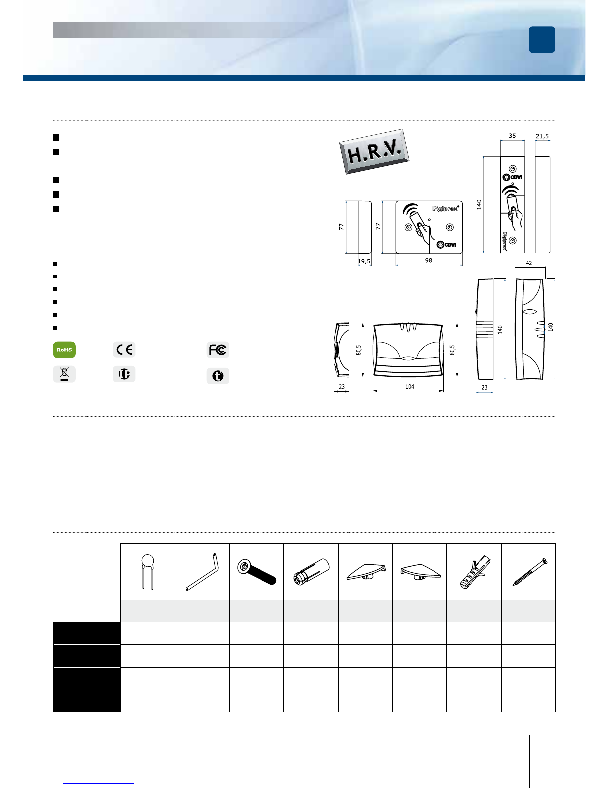
1
Measure and mark the
center lines to determine
the reader position. Drill
the xing screw holes
(Diametre: 4MM for the
mounting plate and 6MM
for the reader). Drill the
wiring access area.
2
DGLIWLC
Insert the brass anchors in the mounting
holes, connect the cable
to the terminal block,
then fasten the reader
with the DIAX
®
screws
using the DIAX® spanner. Make sure that the
varistor is connected on
the lock (refer to page 2
«Recommendations»).
3
DGLPWLC
Insert the plastic anchors in the mounting
holes, connect the
cable to the terminal
block, Then fasten the
reader with the wooden
screws Leave an area
to access the cable to
make
the wiring). Put the
covers on top of the reader.
Make sure that the varistor is connected on
the lock (refer to page
2 «Recommendations»).
1
Measure and mark
the center lines to determine the reader
position. Drill the xing
screw holes (Diametre:
4MM for the mounting
plate and 6MM for the
reader). Drill the wiring
access area.
2
DGLIFWLC
Insert the brass anchors in the mounting
holes, connect the
cable to the connectors,
then fasten the reader
with the DIAX® screws
using the DIAX® spanner. Make sure that the
varistor is connected on
the lock (refer to page 2
«Recommendations»).
3
DGLPFNWLC
Insert the plastic anchors in the mounting
holes, connect the
cable to the terminal
block, then fasten the
reader with the wooden
screws. Put the covers
on top of the reader.
Make sure that the
varistor is connected on
the lock (refer to page 2
«Recommendations»).
4
Optional (MPLATE)
Single gang box mounting plate for the
DGLPFNWLC mullion
polycarbonate proximity
card reader.
Ref : DGLPFNWLC and DGLIFWLC
Make sure that there are no pieces missing in the mounting kit. Get the right tools according to the
installation type (Drill, screw drivers, metre tape,...) and follow the mounting instructions of the reader.
7] MOUNTING INSTRUCTIONS
Ref : DGLPWLC and DGLIWLC
Page 7
7
cdvi.com
cdvigroup.com
FR
DGLPWLC - DGLPFNWLC - DGLIWLC - DGLIFWLC
Lecteurs Proximité Wiegand
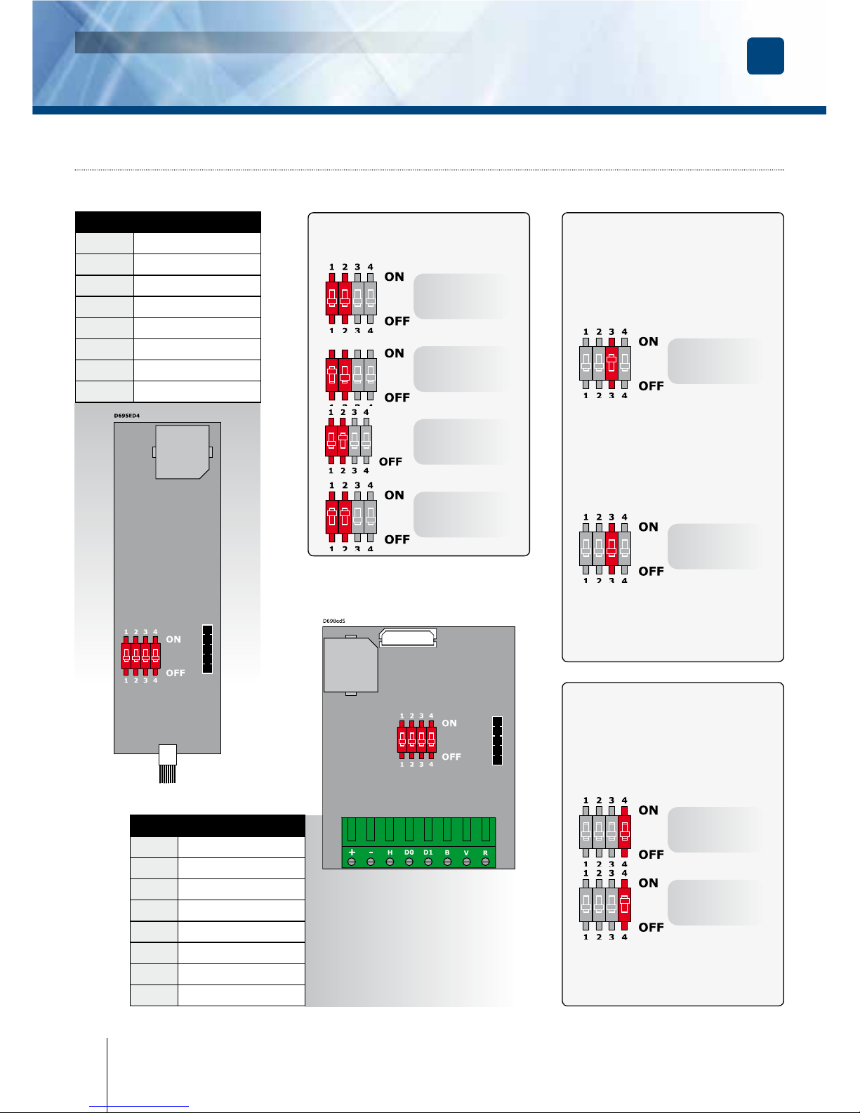
3] ÉLÉMENTS FOURNIS
MANUEL D’INSTALLATION
Varistance
Outil
Diax
®
Vis Diax®
5x35mm
Cheville
métal
Cache Vis
gauche
Cache Vis
droite
Cheville
plastqiue
Vis à bois
3x40mm
DGLIWLC 1 1 2 2 - - - -
DGLPWLC 1 - - - 2 2 2 2
DGLIFWLC 1 1 2 2 - - - -
DGLPFNWLC 1 - - - 2 2 2 2
DGLIWLC
DGLPFNWLC
DGLPWLC
DGLIFWLC
1] PRESENTATION DES PRODUITS
2] RAPPELS ET RECOMMANDATIONS
Recommandations d’installation
Pour sécuriser l’installation, n’oubliez
pas de placer la varistance sur le
système de verrouillage en
parallèle
au niveau de l’alimentation.
Câble préconisés
Câble 4 paires 6/10ème.
Option
Il existe une plaque d’adaptation
en option pour le DGLPFNWLC.
Environnement
Si vous installez ces lecteurs dans
un environnement marin/salin,il
est préconisé de passer du vernis
en bombe sur les contacts après
câblage a n de prévenir le risque
d’oxydation.
Alimentations préconisées
ARD12 et BS60.
HAUTE RÉSISTANCE
AU VANDALISME
IP53
-25°C to +70°C
Certifi cation CE
DEEE
Certifi cation FCC CFR 47
part 15 compliance
Wiegand 26, 30 ou 44 bits.
Connexion directe à la centrale ou via
le contrôleur de porte (INTBUSW).
Electronique résinée.
Signalisation lumineuse et sonore.
Disponible en version :
- Polycarbonate standard “VO” (DGLPWLC).
- Inox (DGLIWLC).
DGLIWLC (L x l x P) : 97 x 76 x 20 mm.
DGLIF WLC (L x l x P) : 140 x 35 x 21,5 mm.
Technologie : 125 Khz.
Protocole : lecteur multi-carte.
Alimentation : 12 V DC.
Consommation : 100 mA.
* Conforme à la directive européenne R&TTE 99/5/CE et selon les normes
harmonisées : ETS 301 489 et ETS
300-330-1-Ed 2001. Conforme aux normes CEM
appliquées :
EN 50133, EN 50130-4.
Page 8
8
cdvi.com
cdvigroup.com
FR
DGLPWLC - DGLPFNWLC - DGLIWLC - DGLIFWLC
Lecteurs Proximité Wiegand
MANUEL D’INSTALLATION
31 2 4
ON
OFF/OFF
26 bits
ON
Mode Centaur
OFF
Pull up 5V
ON/OFF
30 bits
OFF
Mode CDVI
ON
Pull up 12V
OFF/ON
44 bits
ON/ON
Non attribué
DGLPWLC et DGLIWLC
DGLPFNWLC et DGLIFWLC
Vous avez la possibilité
de gérer le buzzer et les
voyants en interne ou en
externe.
Pulls up 12 V ou 5V
Pour les sorties à collecteur
ouvert, il y a deux niveaux
de sorties possibles :
La centrale ou la platine permettent de défi nir les états
de la LED et du buzzer.
En standard, la lecture d’un
badge active la LED orange et
déclenche le buzzer.
La centrale Centaur permet
néanmoins de défi nir d’autres
états pour la LED et le buzzer.
Permet à l’utilisateur de choisir
la tension de sortie en fonction de l’installation.
POSITIONNEMENT
DIPSWITCH 1 & 2
POSITIONNEMENT
DIPSWITCH 3
POSITIONNEMENT
DIPSWITCH 4
4] SCHÉMA DE RACCORDEMENTS : DGLPWLC, DGLIWLC, DGLPFNWLC et DGLIFWLC
Bornier (8 points)
+
Alimentation 12 V DC
- 0V
H Clock
D0 Data 0
D1 Data 1
B Buzzer
V Voyant Vert
R Voyant Rouge
Raccordement
Rouge Input voltage 12VDC
Noir 0V
Bleu Clock
Vert Data 0
Blanc Data 1
Marron Buzzer
Jaune LED Verte
Orange LED Rouge
Page 9
FR
DGLPWLC - DGLPFNWLC - DGLIWLC - DGLIFWLC
Lecteurs Proximité Wiegand
MANUEL D’INSTALLATION
9
cdvi.com
cdvigroup.com
6] FORMAT DE SORTIE WIEGAND 26, 30 ET 44 BITS
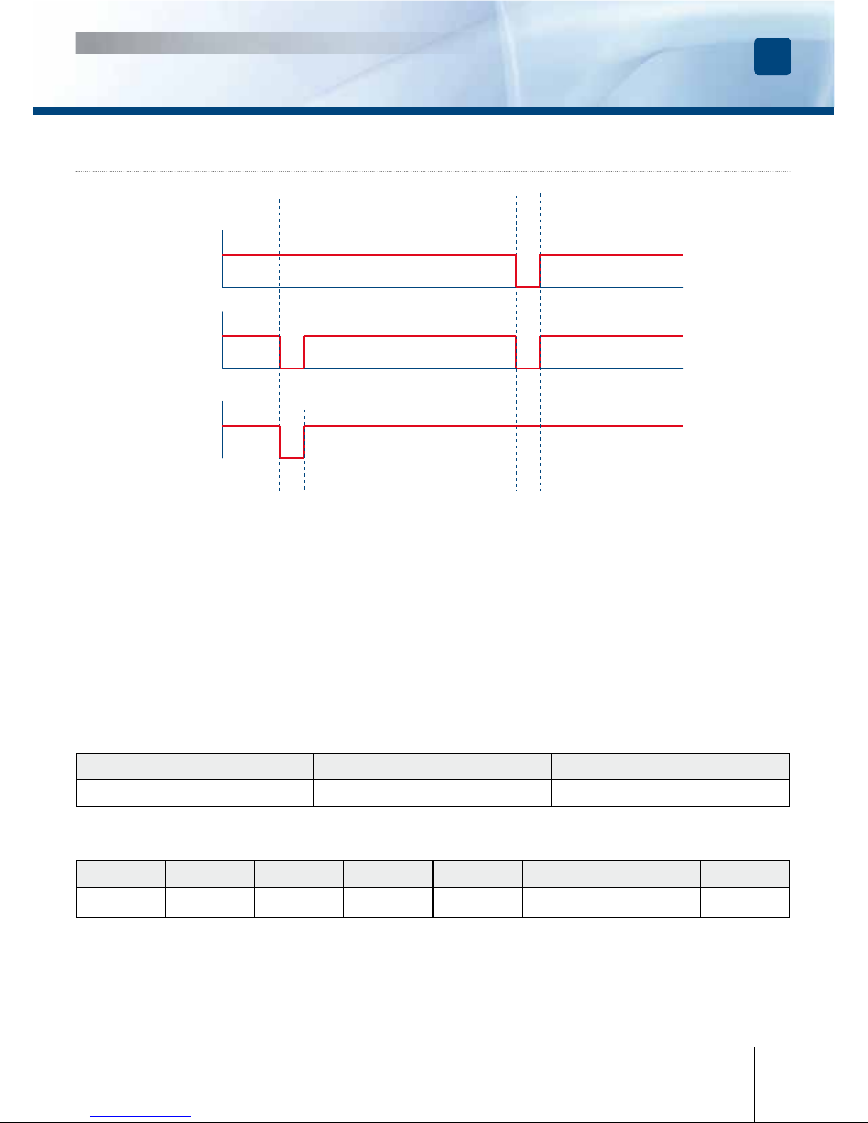
Chronogrammes
Sorties en collecteur ouvert avec pulls up internes de 1K au +5V ou +12V selon la position de ST4
Format Wiegand 26 bits
DGLPWLC - DGLPFNWLC - DGLIWLC - DGLIFWLC > Cavalier ST5 sur 1.
Format 26 bits hexadécimal.
La communication s’effectue par une liaison de type Wiegand 26 bits
(Signaux : DATA1, DATA0 et CLOCK).
La trame est constituée d’une totalité de 26 bits
et se décompose comme suit :
1 - 1ère parité : 1 bit – parité paire des 12 premiers bits
Code du badge : 3 mots d’un octet représentant les 6 derniers termes.
Chaque mot est transmis bit de poids fort en premier.
2 - 2ème parité: 1 bit – parité impaire des 12 derniers bits
Bit 1 Bit 2 à bit 25 Bit 26
Parité paire sur bit 2 à bit 23 Donnée (24 bits)
Parité impaire sur bit 14 à bit 25
Exemple : pour un badge dont le code hexadécimal est 0100166A37.
1 0001 0110 0110 1010 0011 0111 0
Parité 1 1 6 6 A 3 7 Parité 2
Le code émis est 166A37 en hexadécimal
Parité 1 : 0 si le nombre de 1 dans bit 2 à bit 13 est paire,
1 si le nombre de 1 dans bit 2 à bit 13 est impaire.
Parité 2 : 0 si le nombre de 1 dans bit 14 à bit 25 est impaire,
1 si le nombre de 1 dans bit 14 à bit 25 est paire.
0 logique
\DATA1
\CLOCK
\DATA0
50 µs 50 µs
2ms 2ms
1 logique
Page 10
FR
10
cdvi.com
cdvigroup.com
DGLPWLC - DGLPFNWLC - DGLIWLC - DGLIFWLC
Lecteurs Proximité Wiegand
MANUEL D’INSTALLATION
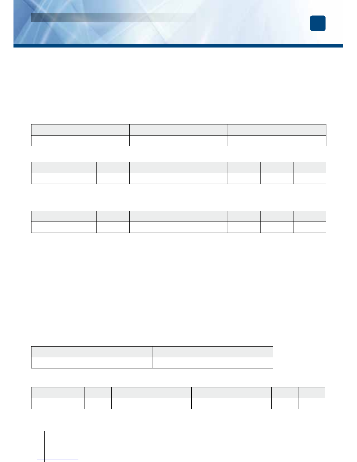
Format Wiegand 30 bits
DGLPWLC - DGLPFNWLC - DGLIWLC - DGLIFWLC > Cavalier ST5 sur 2
Format 30 bits hexadécimal.
La communication s’effectue par une liaison de type Wiegand 30 bits (Signaux :
DATA1, DATA0 et CLOCK).
La trame est constituée d’une totalité de 30 bits et se décompose comme suit :
1 - 1ère parité : 1 bit – parité paire des 14 premiers bits
Code du badge : 7 quartets représentant le code du badge
Chaque mot est transmis bit de poids fort en premier.
2 - 2ème parité: 1 bit – parité impaire des 12 derniers bits
Bit 1 Bit 2 à bit 29 Bit 30
Parité paire sur bit 2 à bit 15 Donnée (28 bits) Parité impaire sur bit 16 à bit 29
Exemple A : pour une carte ayant le code décimal : 689905 (en hexadécimal : A86F1).
1 0000 0000 1010 0110 0110 1111 0001 0
Parité 1 0 0 A 8 6 F 1 Parité 2
Le code émis est 00A86F1 en hexadécimal
Exemple B : pour un badge ayant le code hexa : 0100166A37
1 0000 0000 0001 0001 0110 1011 0110 1
Parité 1 0 0 6 6 A 3 7 Parité 2
Le code émis est 0166A37 en hexadécimal
Parité 1 : 0 si le nombre de 1 dans bit 2 à bit 15 est paire
1 si le nombre de 1 dans bit 2 à bit 15 est impaire
Parité 2 : 0 si le nombre de 1 dans bit 16 à bit 29 est impaire
1 si le nombre de 1 dans bit 16 à bit 29 est paire
Format Wiegand 44 bits
- DGLPWLC - DGLPFNWLC - DGLIWLC - DGLIFWLC > Cavalier ST5 sur 3.
Format 44 bits hexadécimal. La communication s’effectue par une liaison de type Wiegand 44 bits (Signaux :
DATA1, DATA0 et CLOCK). La trame est constituée d’une totalité de 44 bits et se décompose comme suit :
Données : 10 chiffres hexadécimaux (octet de poids fort en premier),
Chaque chiffre hexadécimal = 4 bits (bit de poids fort en premier).
LRC : 4 bit = OU exclusif entre les chiffres de la donnée (bit de poids fort en premier).
Bit 1 à bit 40 Bit 41 à bit 44
Code du badge LRC
Exemple A : pour un badge ayant le code hexa : 01001950C3.
0000 0000 0000 0000 0001 1001 0101 0000 1100 0011 0011
0 1 0 0 1 9 5 0 C 3 3
Le code émis est : 01001950C3 en hexadécimal.
Page 11
FR
DGLPWLC - DGLPFNWLC - DGLIWLC - DGLIFWLC
Lecteurs Proximité Wiegand
MANUEL D’INSTALLATION
11
cdvi.com
cdvigroup.com
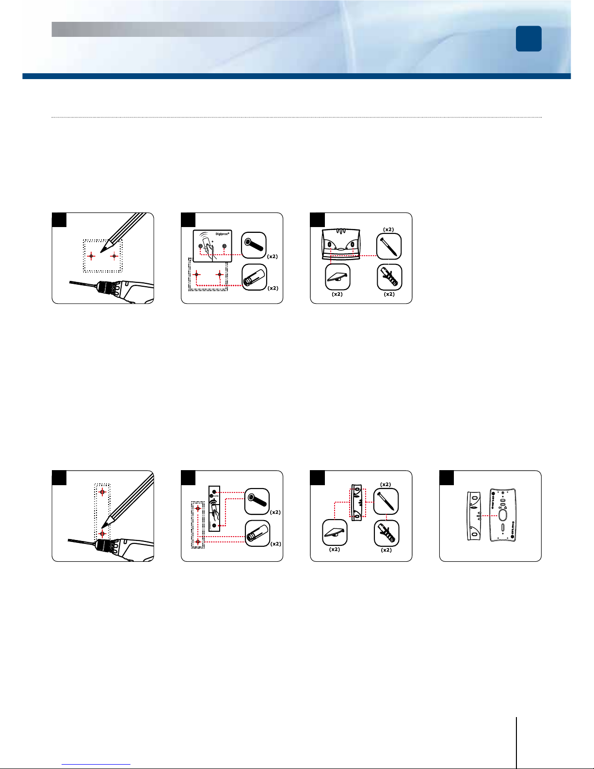
1
A l’aide du lecteur, prenez
les marques pour xer le
produit. Percez le support
de montage au niveau
des marques (Diamètres
de perçage préconisés :
plaque de xation =
4 mm et lecteur = 6 mm).
Grâce à votre schéma
de câblage, prévoyez
la sortie des câbles,
cachés dans la surface ou à
l’extérieur (moulure).
2
DGLIWLC
Placez les chevilles métal
dans les trous, connectez les ls aux borniers
(voir schéma de câblage
page 4), puis xez le
lecteur avec les deux
vis DIAX
®
grâce à l’outil DIAX®. N’oubliez pas
de placer la varistance
au niveau du système de
verrouillage (Voir page 2
«Rappels et préconisations»).
3
DGLPWLC
Placez les chevilles
plastiques dans les
trous, connectez les
ls aux borniers (voir
schéma de câblage
page 4), puis xez les
lecteurs avec les deux
vis à bois. Pour naliser l’installation du lecteur, placez les cachevis. N’oubliez pas de
placer la varistance au
niveau du système de
verrouillage (Voir page 2
«Rappels et préconisations»).
1
A l’aide du lecteur, prenez
les marques pour xer le
produit. Percez le support
de montage au niveau
des marques (Diamètres
de perçage préconisés :
plaque de xation =
4 mm et lecteur = 6 mm).
Grâce à votre schéma
de câblage, prévoyez
la sortie des câbles,
cachés dans la surface ou à
l’extérieur (moulure).
2
DGLIFWLC
Placez les chevilles métal
dans les trous, connectez
les ls aux borniers
(voir schéma de câblage
page 4), puis xez le
lecteur avec les deux
vis DIAX® grâce à l’outil DIAX®. N’oubliez pas
de placer la varistance
au niveau du système de
verrouillage (Voir page 2
«Rappels et préconisations»
).
3
DGLPFNWLC
Placez les chevilles plastiques dans les trous,
connectez les ls aux borniers (voir schéma de câblage page 4), puis xez les
lecteurs avec les deux vis à
bois.
Pour naliser l’installation du lecteur, placez les
cache-vis. N’oubliez pas
de placer la varistance au
niveau du système de
verrouillage (Voir page 2
«Rappels et préconisations»).
4
DGLPFNWLC (Option)
Pour ce lecteur, il existe
une plaque d’adaptation
qui se place entre la surface
de montage et le lecteur.
Cette plaque est non founie
(disponible sur demande).
Réf : DGLPFNWLC et DGLIFWLC
Après avoir véri é que le kit de montage est complet, vous allez pouvoir
procéder à l’installation nale de votre lecteur. Réunissez le matériel approprié
(Perçeuse, tournevis, mètre,...) et suivez les recommandations de montage
qui correspondent au lecteur que vous allez installer.
7] MONTAGE
Réf : DGLPWLC et DGLIWLC
Page 12

Reference : G0301FR0277V10
Extranet : EXE-CDVI_IM DGLP-DGLI WIEGAND CMYK A5 FR-EN 09
Manufacturing Access Control since 1985
cdvigroup.com
All the information contained within this document (photos, drawing, features, specications and dimensions)
could be perceptibly different and can be changed without prior notice.
Toutes les informations mentionnées à titre indicatif sur le présent document (photos, dessins, caractéristiques
techniques et dimensions) peuvent varier et sont susceptibles de modications sans notication préalable.
CDVI Group
FRANCE (Headquarters/Siège social)
Phone: +33 (0)1 48 91 01 02
Fax: +33 (0)1 48 91 21 21
CDVI
FRANCE
Phone: +33 (0)1 48 91 01 02
Fax: +33 (0)1 48 91 21 21
CDVI AMERICAS
[CANADA - USA]
Phone: +1 (450) 682 7945
Fax: +1 (450) 682 9590
CDVI BENELUX
[BELGIUM - NETHERLAND - LUXEMBOURG]
Phone: +32 (0) 56 62 02 50
Fax: +32 (0) 56 62 02 55
CDVI
TAIWAN
Phone: +886 (0)42471 2188
Fax: +886 (0)42471 2131
CDVI
SWITZERLAND
Phone: +41 (0)21 882 18 41
Fax: +41 (0)21 882 18 42
CDVI
CHINA
Phone: +86 (0)10 87664065
Fax: +86 (0)10 87664165
CDVI IBÉRICA
[SPAIN - PORTUGAL]
Phone: +34 (0)935 390 966
Fax: +34 (0)935 390 970
CDVI
ITALIA
Phone: +39 0331 97 38 08
Fax: +39 0331 97 39 70
CDVI
MAROC
Phone: +212 (0)5 22 48 09 40
Fax: +212 (0)5 22 48 34 69
CDVI SWEDEN
[SWEDEN - DANEMARK - NORWAY - FINLAND]
Phone: +46 (0)31 760 19 30
Fax: +46 (0)31 748 09 30
CDVI UK
[UNITED KINGDOM - IRELAND]
Phone: +44 (0)1628 531300
Fax: +44 (0)1628 531003
DIGIT
FRANCE
Phone: +33 (0)1 41 71 06 85
Fax: +33 (0)1 41 71 06 86
 Loading...