

Page 1
RS-990
Power Solutions
LIBERTY®SERIES 1000
Valve-regulated Lead Acid Batteries
Installation and Operating Instructions
Page 2
SAFETY PRECAUTIONS
Only authorized and trained personnel familiar with standby battery installation, preparation, charging and
maintenance should be permitted access to the battery.
WARNING
SHOCK HAZARD - DO NOT TOUCH UN-INSULATED BATTERY, CONNECTORS OR TERMINALS.
BE SURE TO DISCHARGE STATIC ELECTRICITY FROM TOOLS AND TECHNICIAN BY TOUCHING
A GROUNDED SURFACE IN THE VICINITY OF THE BATTERIES BUT AWAY FROM THE CELLS
AND FLAME ARRESTERS.
ALL TOOLS SHOULD BE ADEQUATELY INSULATED TO AVOID THE POSSIBILITY OF SHORTING
CONNECTIONS. DO NOT LAY TOOLS ON THE TOP OF THE BATTERY.
®
ALTHOUGH LIBERTY
MAL OPERATION, THEY CONTAIN POTENTIALLY EXPLOSIVE GASES, WHICH MAY BE RELEASED
UNDER ABNORMAL OPERATING CONDITIONS, SUCH AS A CHARGER MALFUNCTION. PROVIDE
ADEQUATE VENTILATION SO HYDROGEN GAS ACCUMULATION IN THE BATTERY AREA DOES
NOT EXCEED ONE PERCENT BY VOLUME. HOWEVER, NORMAL AIR CIRCULATION IN A VENTILATED FACILITY WILL PRECLUDE ANY HYDROGEN BUILD-UP, EVEN DURING EQUALIZE CHARGING. NEVER INSTALL BATTERIES IN A SEALED CABINET OR ENCLOSURE. IF YOU HAVE ANY
QUESTIONS, CONTACT YOUR LOCAL C&D TECHNOLOGIES AGENT.
SERIES 1000 BATTERIES ARE SEALED AND EMIT NO GAS DURING NOR-
THIS BATTERY CONTAINS
SKIN CONTACT WITH ELECTROLYTE, REMOVE CONTAMINATED CLOTHING AND FLUSH
AFFECTED AREAS THOROUGHLY WITH WATER. IF EYE CONTACT HAS OCCURRED, FLUSH
FOR A MINIMUM OF 15 MINUTES WITH LARGE AMOUNTS OF RUNNING WATER AND SEEK
IMMEDIATE MEDICAL ATTENTION.
THIS BATTERY IS DESIGNED FOR
APPLICATION IN VEHICULAR STARTING, LIGHTING AND IGNITION AND/OR OPERATION OF
PORTABLE TOOLS AND APPLIANCES. USE ONLY IN ACCORDANCE WITH MANUFACTURER’S
WRITTEN INSTRUCTIONS. USE OF THIS PRODUCT OTHER THAN IN ACCORDANCE WITH
MANUFACTURER’S WRITTEN INSTRUCTIONS MAY PRODUCE HAZARDOUS AND UNSAFE
OPERATING CONDITIONS, LEADING TO DAMAGE OF EQUIPMENT AND/OR PERSONAL INJURY.
SULFURIC ACID, WHICH CAN CAUSE SEVERE BURNS. IN CASE OF
INDUSTRIAL USE ONLY AND IS NOT INTENDED FOR
IMPORTANT FOLLOW MANUFACTURER’S PUBLISHED INSTRUCTIONS WHEN INSTALLING, CHARGING AND
SERVICING BATTERIES. THIS MANUAL IS TO BE USED FOR THE INSTALLATION AND
OPERA
TION OF C&D
TECHNOLOGIES
VE-REGULA
AL
V
TED LIBERTY SERIES 1000 BATTERIES.
Page 3

FOR ADDITIONAL INFORMATION CONTACT:
C&D Technologies, Inc.
1400 Union Meeting Road, PO Box 3053
Blue Bell, PA 19422-0858
215-619-2700 or 1-800-543-8630, Fax 215-619-7899
www.cdtechno.com
FOR TECHNICAL or WARRANTY ASSISTANCE CONTACT:
Technical Service Department located at:
1400 Union Meeting Road
Blue Bell, PA 19422
215-619-2700 or 1-800-543-8630, Fax 215-619-7842
WARRANTY NOTICE
This instruction manual is not a warranty. Each standby battery is sold subject to a limited
warranty, which is in place of all other warranties, express or implied (including the warranties of
merchantability or fitness for a particular purpose) and which limits a purchaser’s (user’s)
remedy to the repair or replacement of a defective battery or parts thereof. The terms of the
limited warranty are incorporated herein and are available upon written request from C&D
Technologies, Inc., 1400 Union Meeting Road, PO Box 3053, Blue Bell, PA 19422-0858 or in
Canada C&D Technologies, Inc., Canada, 7430 Pacific Circle, Mississauga, ON
L5T 2A3.
1
Page 4

INTRODUCTION
The batteries referenced in this document are valve-regulated lead acid Liberty Series 1000®.
They are constructed with pasted lead calcium plates with an absorbent glass mat and are
valve-regulated.They are designed to provide long, reliable service life with minimal
maintenance. The cells/units are shipped pre-assembled in 2-, 4-, 6- and 12-Volt modules to
enable quick and easy installation. When operated at the recommended float voltage and
temperature, the batteries emit virtually no gas or acid mist and do not need special
ventilation other than what is required by local building codes. This makes Liberty Series
1000 batteries an ideal reserve power source for many critical applications, including
telecommunications, switchgear and control, and uninterruptible power supply (UPS)
systems. The Liberty Series 1000 product brochure and additional information are available
on the C&D Technologies website at www.cdtechno.com.
Recombination: A More Efficient Design
In addition to eliminating the need for watering, the uniquely efficient recombination design
also makes Liberty Series 1000 batteries lighter and more powerful than conventional lead-
. Oxygen evolves from the positive plates where it is converted back to water
acid batter
ies
by electro chemical recombination, eliminating the need for watering.
CAUTION:
Do not remo
ve vent covers, they must remain in place at all times. Removal
will void warranty.
Specifications are subject to change without notice
. Contact your C&D Technologies sales
office for the latest specifications. All statements, information and data given herein
are belie
ved to be accurate and reliab
le but are presented without guaranty, warranty, or
responsibility of any kind, express or implied. Statements or suggestions concerning possible use of our products are made without representation or warranty that any such use is
free of patent infr
ingement, and are not recommendations to infringe any patent.
The user
should not assume that all safety measures are indicated, or that other measures may not be
required.
2
Page 5

RECOMMENDED TECHNICAL REFERENCES AND EXPERTISE
These instructions assume a certain level of competence by the installer/user. The following
recommended practices and codes contain relevant information, and should be consulted for safe
handling, installation, testing and maintaining standby batteries. Applicable state and local codes must
be followed.
IEEE Std. 485-1997, IEEE Recommended Practice for Sizing Large Lead Acid Storage Batteries for Generating
Stations and Substations (ANSI)
IEEE 1189-1996, IEEE Guide for Selection of Valve-Regulated Lead Acid (VRLA) Batteries for Stationary
Applications
IEEE 1188-1996, IEEE Recommended Practice for Maintenance, Testing, and Replacement of Valve Regulated
Lead-Acid Storage Batteries for Stationary Applications
IEEE 1187-2000, IEEE Recommended Practice for Installation Design and Installation of Valve Regulated LeadAcid Storage Batteries for Stationary Applications
IEEE - PAR-1375-1998 “Guide for Protection of Stationary Battery Systems”
NESC, National Electric Safety Code, ANSI C2-1993 (or latest revision)
Copies may be obtained by writing: The Institute of Electrical and Electronic Engineers, Inc.
345 East 47th Street, New York, NY 10017, USA
ANSI - T1.330-1997, Valve-Regulated Lead Acid Batteries Used in the Telecommunications Environment
NEC National Electrical Code NFPA -70 (latest version) available from:
National Fire Protection Association Batterymarch Park, Quincy, MA 02269
Federal Codes:
ety Requirements f
29CFR1926.441
29CFR1910.151(c) “Medical Services and First Aid”
29CFR1910.268(g) “Telecommunications”
29CFR1910.305(j) “Wiring Methods, Components and Equipment”
STD 1-8.2(e)
IBC, International Building Code
This manual is divided into four parts: Receiving and Installation of the battery, Operation and Maintenance,
Reference and Trouble-Shooting section to assist the user should he require more detailed explanation of battery
performance and maintenance procedures, and the Appendix.
Before handling cells or storing cells for future installation take time to read this manual. It contains
information that could avoid irreparable damage to the battery and/or void product warranty.
“Saf
“
OSHA Standing Directive”
or Special Equipment”
3
Page 6

LIBERTY SERIES 1000
ALVE-REGULATED (SEALED) LEAD ACID BATTERIES
V
INSTALLATION AND OPERATING INSTRUCTIONS
TABLE OF CONTENTS PAGE
INTRODUCTION. . . . . . . . . . . . . . . . . . . . . . . . . . . . . . . . . . . . . . . . . . . . . . . 2
Recombination: a more efficient design
Recommended Practices, Technical Sources
PART 1
RECEIVING AND INSTALLATION . . . . . . . . . . . . . . . . . . . . . . . . . . . . . . . . . 6
SECTION 1 - RECEIVING . . . . . . . . . . . . . . . . . . . . . . . . . . . . . . . . . . . . . . . 6
1.1 General Information and precautions
1.2 Safety
1.3 Packing, Inspection at time of delivery
1.4 Damage and shortage situations
1.5 Unpacking and handling
SECTION 2 - STORAGE and SHELF LIFE . . . . . . . . . . . . . . . . . . . . . . . . . . 7
2.1 Storing charged batteries
SECTION 3 - INSTALLATION AND ASSEMBLY . . . . . . . . . . . . . . . . . . . . . . 8
3.1 Location and preparation
3.2 Ventilation
3.3 Modular rack assembly
3.4 Relay rack assembly
3.5 Optional steel jackets for batteries/units operating in a demanding
environment
SECTION 4 - ELECTRICAL CONNECTIONS
4.1 Preparing electrical contacting surfaces
4.2 Polarity inspection of assembled units and inter-row, inter-tier connections
4.3 Connecting and torquing battery terminal posts
4.4 Checking connection integrity
4.5 Parallel battery strings
PART 2
CHARGING AND OPERATION OF BATTERY. . . . . . . . . . . . . . . . . . . . . . . 16
SECTION 1 - CHARGING . . . . . . . . . . . . . . . . . . . . . . . . . . . . . . . . . . . . . . 16
1.1 General information and precautions
1.2 Initial charge
1.3 Constant voltage charging
1.4 Initial charge records
1.5 Warning labels
. . . . . . . . . . . . . . . . . . . . . . .
12
4
Page 7

SECTION 2 - BATTERY OPERATION . . . . . . . . . . . . . . . . . . . . . . . . . . . . . 18
2.1 Float charging
2.2 Equalizing charge
2.3 Over-voltage
2.4 Voltmeter calibration
SECTION 3 - GENERAL INFORMATION AND MAINTENANCE. . . . . . . . . 20
3.1 Performance characteristics
3.2 Capacity and testing
3.3 Low cell voltages
3.4 Effects of temperature
3.5 High ambient temperature
3.6 Cleaning cell covers
3.7 Tap connections
3.8 Putting batteries into storage
3.9 Record keeping
PART 3
TROUBLE-SHOOTING and AVOIDING BATTERY DEGRADATION and
RECOGNIZING PROBLEMS . . . . . . . . . . . . . . . . . . . . . . . . . . . . . . . . . . . . 26
SECTION 1 - HOW TO AVOID BATTERY DEGRADATION . . . . . . . . . . . . . 26
1.1 General information and precautions
1.2 Float versus cycle life
1.3 Low float voltage and sulfation
1.4 Hydration
1.5 Open circuit - late installations
1.6 Parallel battery strings
1.7 High temperature operation
APPENDIX A - MATERIAL SAFETY DATA SHEETS . . . . . . . . . . . . . . . . . . 29
APPENDIX B - WARRANTY PROVISIONS . . . . . . . . . . . . . . . . . . . . . . . . . 35
APPENDIX C - VALVE REGULATED LEAD ACID BATTERY and
CHARGER INSPECTION REPORT FORM . . . . . . . . . . . . 36
5
Page 8

PART 1
RECEIVING AND INSTALLATION
SECTION 1 - RECEIVING
1.1 General Information and Precautions
This battery is designed for industrial use only and is not intended for
application in vehicular starting, lighting, and ignition, and/or operation
of portable tools and appliances. Use only in accordance with
manufacturer’s written instructions. Use of this product other than in
accordance with manufacturer’s written instructions may produce
hazardous and unsafe operating conditions, leading to damage of
equipment and/or personal injury.
1.2 Safety
Charge only in accordance with manufacturer’s operating instructions.
Do not expose to open flame or electrical arc.
Do not tamper with cell covers that prevent access to vents.
Observe all precautions shown on the inside cover of this manual.
1.3 Packing, Inspection at time of delivery
Every precaution has been taken to pack the battery for shipment to
ensure its safe arrival. As soon as you receive the battery, check the
packing mater
ial for evidence of damage in transit. If the packing
material is physically damaged or wet acid stains are present, make a
notation on the delivery receipt
before you accept the shipment/
delivery.
Note: Freight Carriers generally require that the carriers’
representativ
e inspect concealed damage within 15 days
from date of delivery to determine responsibility. The
xtend up to 9 months.
resolution of such claims ma
erify the number of cartons and skids against the bill of lading and
V
ify the components against the pac
er
v
y e
king lists
Keep a copy of the
.
verified lists for your installation records. It is important to verify that
the accessor
correct.
y package is present and the component quantity is
echnologies
If help is required call y
our local C&D
T
Representative or C&D Technologies Customer Service at 800-5438630 to report any discrepancies.
1.4 Damage and shortage situations
C&D
echnologies ships FOB plant (o
T
wnership passes at our doc
k). If
shipments are damaged or if cartons or skids are damaged or missing,
a claim must be filed with the carrier. Place an immediate
echnologies and use the replace-
order f
or replacement with C&D
T
ment cost as the amount of freight that damages or shortages
involved. If individual components or parts are missing, a shortage
t should be fi
repor
led immediately with C&D
Technologies. Mail
(express mail recommended) or fax a copy of the VERIFIED compo-
6
Page 9

nent packing list. This verified list should show both the name of the
packer, as well as the quantities of items checked off by the receiver.
Send the list to:
C&D Technologies, Inc.
Attn.: Customer Service
1400 Union Meeting Road
Blue Bell, PA 19422
SECTION 2 - STORAGE and SHELF LIFE
2.1 Storage of VRLA (valve regulated lead acid) Batteries
Store batteries indoors, preferably at 77°F (25°C) or in a cool 20°F to
90°F (-7°C to 32°C), dry location and place on charge by the
date
found on the battery carton.
Note:
Batteries that are not placed in service for several months will
self-discharge.
Storage time is based on storage at 77°F (25°C) and is six months for
valve regulated cells. Do not allow the electrolyte
Liberty Series
1000
to freeze, as this will destroy the battery and can cause a potentially
hazardous condition and leakage.
Refer to Table 1, for electrolyte freezing temperatures. Although the
specific gravity of a fully charged battery may present no freezing
lem, a discharged battery gravity may freeze at relatively mild
prob
temperatures.
TABLE 1 - FREEZING TEMPERATURE VS SPECIFIC GRAVITY
Specific Gravity Freezing Temperature
at 77°F (25°C)
ahrenheit
Celsius
1.000
1.050
1.100 -7.7 +18
1.150 -15 + 5
1.200
1.250 -52 -61
1.300 -70 -95
1.350
1.400 -36 -33
0.0 +32
-3.3 +26
-27 -17
-49 -56
F
Note: Store cells upr
ight in order to maximiz
e electrolyte contact with
the plates.
e limitations
2.2 Stora
g
C&D Technologies Liberty Series 1000 valve-regulated (sealed) lead
7
Page 10

acid batteries are warranted against defects in materials or manufacturing or both. To keep the warranty in effect, you must place the units
on charge by the date stamped on the shipping carton when stored at
77°F (25°C). If storage beyond this time is required or storage temperature is in excess of 77°F (25°C), monitor battery voltage at monthly
intervals, if possible. A convenient measurement technique is to read
the open circuit voltage. If the open circuit voltage drops below 2.10
volts per cell from the nominal value, the cell(s) must be given a boost
charge at the “Initial/Equalize” voltage shown in Table 2. With the
exception of the LS 2-600 all units consist of multiple cells. Refer to
Table 2 for the nominal voltage and number of cells for a particular
Liberty Series unit. Ne
ver charge the cells at a higher voltage than the
equalize/ boost voltage recommended in Table 2, at 77°F (25°C). If
cell temperature is below 60°F (16°C), double the initial/equalize
charge time that is typically 12-16 hours at 77°F (25°C).
If this is not possible, contact C&D Technologies, Inc., Technical
Services Department for special instructions.
Always complete a record of initial charge, refresh charges during
storage, and fl
t 2, Section 1.2 using RS-1511 of this manual and retain the
Par
oat charge readings as described in
“initial charge”
readings in your files for future reference. Clearly identify your installation location, application, C&D Technologies model n
umber
, the date,
and name of the person who took the readings.
The ser
vice life of the battery will depend on its ambient temper
ature,
frequency and depth of discharge, discharge rate, charge voltage, and
regulation of the battery charger.
SECTION 3 - INST
ALLATION AND CONNECTION
3.1 Location and Preparation
ies 1000 batteries are best installed upright. Physical
ty Ser
Liber
dimensions for layout may be found in Table 2. Install battery in a cool,
dry location away from heat sources.The recommended operating
temper
ature is 65-77
°F (18-25°C). The allowable temperature range
with performance degradation at the extreme temperatures is 32-90°F
(0-32°C). Float voltage compensation should be made for temperatures
F (25°C).
other than 77
°
Avoid sources of hot or cold air directed on a section of the
batter
y that could cause temperature variations within the
battery assembly. Such variations will compromise optimum
battery performance such as float voltages of individual cells.
When handling units never lift them by the terminals as this can
damage the post seals and cause acid leakage.
8
Page 11

TABLE 2 - BATTERY SPECIFICATIONS
(Characteristics subject to change without notice. Refer to current specifications 12-373)
Model LS 12-25* LS 6-50* LS 12-55 LS 12-80
Nominal voltage 12 Volts 6 Volts 12 Volts 12 Volts
Number of cells in 6/unit 3/unit 6/unit 6/unit
module
Rated 8 hr. 25 Ah 50 Ah 52 Ah 80 Ah
Capacity (Ampere- to to to to
hours to 1.75 Vpc) 10.50 Volts 5.25 Volts 10.50 Volts 10.50 Volts
Rated 15-min. capacity 0.092 0.185 0.172 0.275
(kiloWatts to 1.67 Vpc)
Internal resistance/cell 0.0017 Ohms 0.0008 Ohms 0.00157 Ohms 0.00094 Ohms
Short circuit current 1155 A 2310 A 1274 A 2128 A
Unit height 7.11 in 7.11 in 9.20 in 9.20 in
(181 mm) (181 mm) (234 mm) (234 mm)
Unit length 7.64 in 7.64 in 10.20 in 13.94 in
(includes handles) (194 mm) (194 mm) (234 mm) (354 mm)
Unit width 5.20 in 5.20 in 6.80 in 6.80 in
(132 mm) (132 mm) (173 mm) (173 mm)
Weight 23 lbs 23 lbs 56 lbs 79 lbs
(10 kg) (10 kg) (25 kg) (36 kg)
Terminal 0.55 in (14 mm) 0.55 in (14 mm) 0.55 in (14 mm) 1.00 in (25 mm)
Characteristics diameter threaded diameter threaded diameter threaded diameter threaded
brass insert, 0.50 brass insert, 0.50 brass insert, 0.50 brass insert, 0.75
in (13 mm) deep. in (13 mm) deep. in (13 mm) deep. in (19 mm) deep.
Fasten with 10-32 Fasten with 10-32 Fasten with 10-32 Fasten with 1/4-20
stainless steel stainless steel stainless steel stainless steel
hex bolt/washer hex bolt/washer hex bolt/washer hex bolt/washer
Tightening torque 45 in-lbs (5.1 N*m) 45 in-lbs (5.1 N*m) 45 in-lbs (5.1 N*m) 110 in-lbs (12.4 N*m)
Re-torque 40 in-lbs (4.5 N*m) 40 in-lbs (4.5 N*m) 40 in-lbs (4.5 N*m) 100 in-lbs (11.3 N*m)
Boost charge voltage 2.33 +/-.02 Vpc 2.33 +/-.02 Vpc 2.33 +/-.02 Vpc 2.33 +/-.02 Vpc
Nominal float voltage 2.26 +/-.01 Vpc 2.26 +/-.01 Vpc 2.26 +/-.01 Vpc 2.26 +/-.01 Vpc
Electrolyte at 77°F 1.300 Specific 1.300 Specific 1.300 Specific 1.300 Specific
(25°C) nominal value Gravity Gravity Gravity Gravity
*These units ha
ve been discontinued
9
Page 12

TABLE 2 (CONTINUED)
Model LS 12-100 LS 6-200 LS 4-300 LS 2-600
Nominal voltage 12 Volts 6 Volts 4 Volts 2 Volts
Number of cells in 6/unit 3/unit 2/unit 1/unit
module
Rated 8 hr. 100 Ah 200 Ah 300 Ah 600 Ah
capacity (Ampere- to to to to
hours to 1.75 Vpc) 10.5 Volts 5.25 Volts 3.5 Volts 1.75 Volts
Rated 15-min capacity 0.344 0.688 1.032 2.063
(kiloWatts to 1.67 Vpc)
Internal resistance/cell 0.0008 Ohms 0.0004 Ohms 0.0003 Ohms 0.0001 Ohms
Short circuit current 2545 A 5089 A 7634 A 15267 A
Unit height 9.20 in 9.20 in 9.20 in 9.20 in
(234 mm) (234 mm) (234 mm) (234 mm)
Unit length 16.58 in 16.58 in 16.58 in 16.58 in
(includes handles) (421 mm) (421 mm) (421 mm) (421 mm)
Unit width 6.84 in 6.84 in 6.84 in 6.84 in
(174 mm) (174 mm) (174 mm) (174 mm)
Weight 95 lbs 95 lbs 95 lbs 95 lbs
(43 kg) (43 kg) (43 kg) (43 kg)
Terminal 1.00 in (25 mm) .00 in (25 mm) 1.00 in (25 mm) 1.00 in (25 mm)
characteristics diameter threaded diameter threaded diameter threaded diameter threaded
brass insert, 0.75 brass insert, 0.75 brass insert, 0.75 brass insert, 0.75
in (19 mm) deep. in (19 mm) deep. in (19 mm) deep. in (19 mm) deep.
Fasten with 1/4-20 Fasten with 1/4-20 Fasten with 1/4-20 Fasten with 1/4-20
stainless steel stainless steel stainless steel stainless steel
hex bolt/washer hex bolt/washer hex bolt/washer hex bolt/washer
Tightening torque 110 in-lbs
Re-torque 100 in-lbs
Boost c
Nominal float voltage 2.26 +/-.01 Vpc 2.26 +/-.01 Vpc 2.26 +/-.01 Vpc 2.26 +/-.01 Vpc
Electrolyte at 77°F (25°C) 1.300 Specific 1.300 Specific 1.300 Specific 1.300 Specific
nominal value Gravity Gravity Gravity Gravity
harge voltage 2.33 +/-.02 Vpc 2.33 +/-.02 Vpc 2.33 +/-.02 Vpc 2.33 +/-.02 Vpc
(12.4 N*m)
(11.3 N*m)
110 in-lbs
100 in-lbs
(12.4 N*m)
(11.3 N*m)
110 in-lbs
100 in-lbs
(12.4 N*m)
(11.3 N*m)
110 in-lbs
100 in-lbs
(12.4 N*m)
(11.3 N*m)
3.2 Ventilation
ies 1000 battery is a valve-regulated, low-maintenance battery, which, under normal float
The Liber
ty Ser
conditions, requires only normal room ventilation. Therefore, under normal float operation, Liberty batteries
can be installed in proximity to electronic equipment and in computer rooms with personnel present.
However, should the battery be subjected to excessive overcharge, hydrogen and oxygen can be vented to
the atmosphere.
precautions m
10
Therefore, the battery should never be installed in an airtight enclosure. Sufficient
ust be taken to prevent excessive overcharge and containment of potential gases.
Page 13
VRLA batteries when subjected to extreme overcharge (above the
recombinant ability of the cell) can release hydrogen gas at a
maximum rate of 0.000269 cubic feet per minute per ampere of
charging current at 77°F (25°C) at atmospheric pressure.
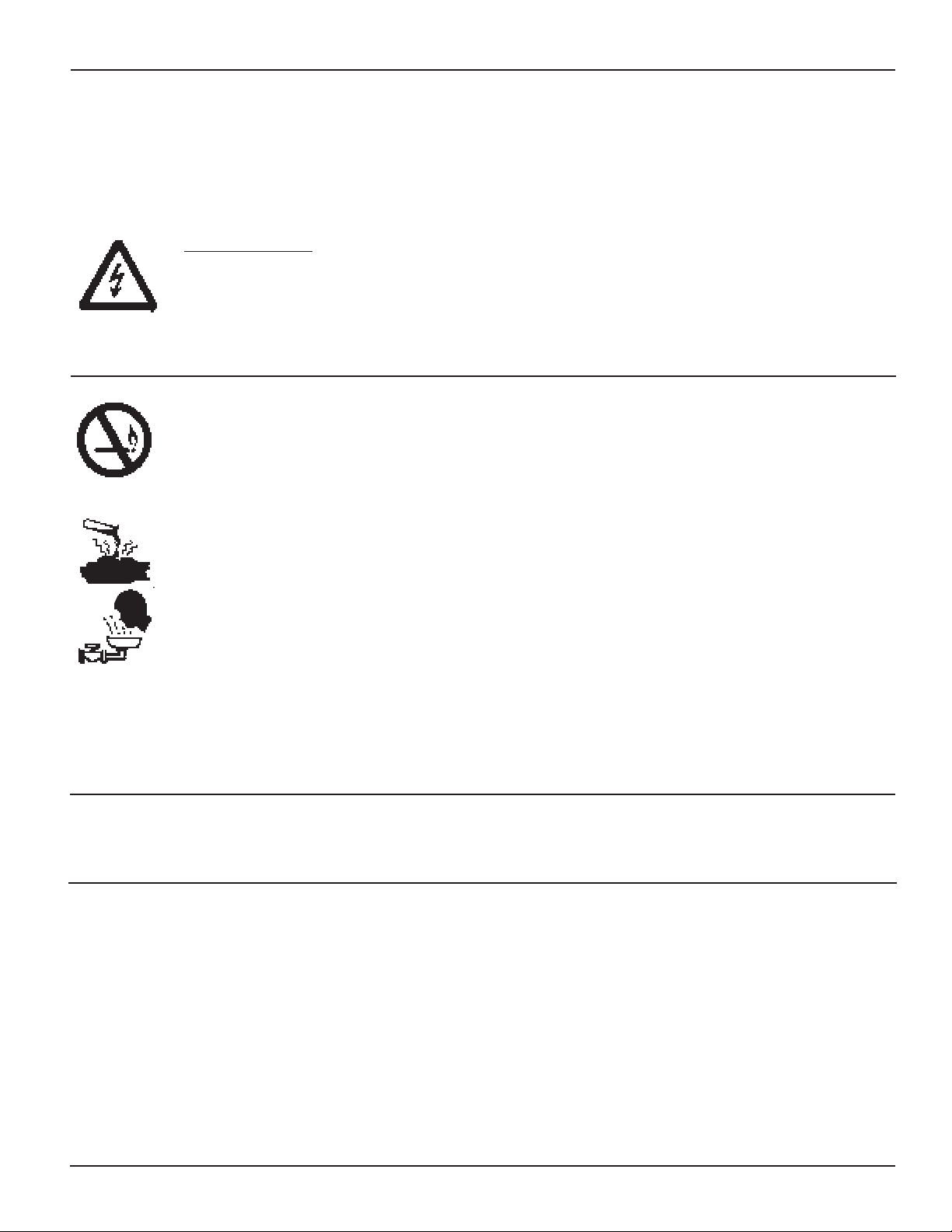
3.3 Rack Assemblies
Liberty Series 1000 batteries may be installed in a variety of
mounting assemblies
• Modular Rack assembly (Figure 3.1) - battery units may be assembled in a floor mounted module or rack. One modular rack available
from C&D Technologies, Inc. is designed to mount the units in a
sturdy open frame that is stackable. They are available in 29" and
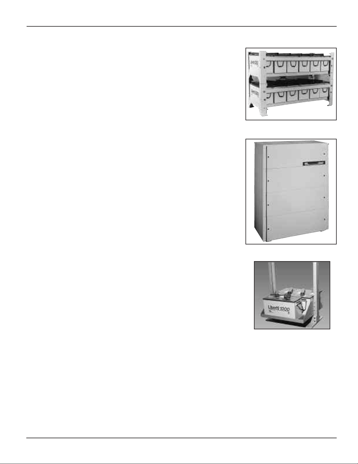
43" (74 cm and 109 cm) lengths. Optional panels are available to
enclose the racks, providing a cabinet-like appearance. (Figure 3.2)
For additional information refer to specification 12-373 and 12-380.
• When large numbers of batteries are required for the application
and a dedicated battery room may be provided, conventional tiered
ks may be appropriate.
rac
FIGURE 3.1 - Modular Rack Assembly
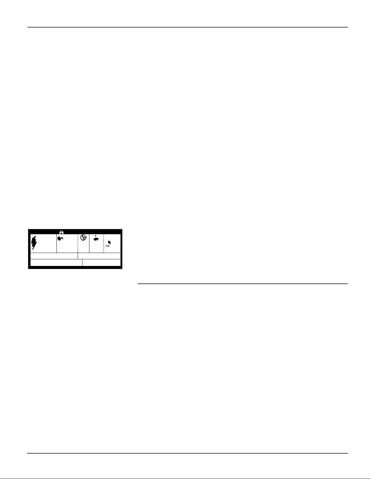
3.4 Relay Rack Assemb
ly
• Battery units can be mounted in standard 19" and 23" (48 cm and
ames. A typical C&D Technologies “tray layout” is
58 cm) relay rac
shown in Figure 3.3.
k fr
Specially designed trays/fixtures should be
ordered for relay rack applications.
3.5 Optional Steel Jackets for Batteries/Units operating in a
demanding environment
Although a metal jacket cannot change the thermal degradation or
electro/chemical properties of the battery exposed to elevated
temper
atures, it will physically contain the cells exposed to elevated
temperatures by retaining compression on the positive and negative
plates and absorbent glass mat between the plates.The net effect and
pose is that the plates are pro
pur
contained electrolyte
.
vided with a uniform exposure to the
Note: Optional steel jackets are recommended if the batteries are
xpected to e
e
xperience frequent periods of operation at
temperatures in excess of 90°F (33°C).
FIGURE 3.2 - Modular Rack With Panels
FIGURE 3.3 - Relay Rack Trays
11
Page 14

SECTION 4 - ELECTRICAL CONNECTIONS
WARNING
• Always use protective insulating equipment, such as gloves,
shoes and eye and face protection. Wrenches and other tools
must be insulated.
• Observe local, state, and national electric codes at all times.
• Always work with the battery ungrounded. Battery ground
connections, if required, should be made last.
• To avoid working with high voltages, break the battery down
into convenient lower-voltage modules, i.e., equal to or less
than 48-Volts.
ays maintain a firm grasp on tools and hardware when
• Alw
working on the battery. Dropped hardware can cause a short
circuit, possibly resulting in serious personal injur
y and/or
damage to the equipment.
king on the battery, be sure to discharge static
• Before w
electricity that can b
or
uild up on tools or the technician by touching
a grounded surface in the vicinity of the battery but far enough
away from the cells and fl
ame arresters. Avoid creating sparks or
exposing cells to open flames that could ignite the gasses
produced by a charging battery.
4.1 Preparing electrical contacting surfaces
All electrical contacting surfaces must have a clean and electrolyte
free finish. Any tarnish or discoloration should be carefully removed.
Do not use steel br
y posts and intercell connectors
batter
ushes or other abr
asive tools to clean the tin plated
.
The posts and inter
cell
connectors are plated with a thin layer of tin. Cable lugs are tin
plated. It is important that the electro-plating m
ed or removed.
g
dama
ust not be
1. With a dry cloth, remove any factory-applied grease or oil coating
from the contact surf
aces or posts
.
2. Brush the contacting surfaces of battery posts/terminals and
intercell connectors to a clean corrosion free fi
nish using a
ne
fi
brass plater’s wire brush (multiple 0.010 diameter brass wire
construction).
3. After brushing connections with a fine brass plater’s brush,
terminals and interface can be coated with NO-OX which prevents
xidation between connections.
o
12
Page 15

CAUTION
Do not use steel brushes, steel wool, sandpaper or emery cloth
to clean surfaces, as these will damage the plating. Do not use
cleaning solvents. Solvents can cause crazing or cracking of
the plastic cell containers or covers. Use of solvents will void
the warranty.
4. Attach intercell connectors or cable/lugs from the positive post of
one unit to the negative post of the next cell or unit for series
connection. If the units are mounted on more than one tier make
certain to follow the polarity convention, positive post to negative
post. Inter-tier and inter-row connections are typically made with
cables with lugs on both ends. Do Not Use Steel or Cadmium
Plated Lugs.
5. Large batteries may use “Terminal Plates” to accommodate
multiple cable connections.There are a variety of optional terminal
plates availab
le from C&D Technologies, Inc., Inc. Terminal plates
should be clean and prepared in the same manner as the intercell
connectors.
4.2 Polarity of assembled units/cells and inter-row, inter-tier
connections
LS 12-100 Inter-Tier Connection
Cell/unit polarities have been marked by a raised mark in the covers to
provide proper interconnection between cells.When connecting
cells/units be sure that all ter
minals, including inter-tier, have been
connected positive (+) to negative (-) from one cell/unit to another
throughout the battery.
4.3 Connecting and torquing battery terminal posts
Liberty Series 1000 batteries are available in various sizes and volt-
able 2 and with corresponding Ampere-hour
ages as descr
ibed in
T
ratings at the 8 hour rate of discharge: 80 Ah, 100 Ah, 125 Ah, 200
Ah, 300 Ah, and 600 Ah. The units are connected positive to negative
from one unit to another unit in a series arrangement. This is accomplished by fastening the tin plated connector (used on larger size
units) or lugs found on cables (for smaller size units) from the positive
terminal of a unit to the negative terminal of the next unit. The lug or
connector is secured with the appropriate terminal hardware
described in Table 2 and tightened to the torque value specified in
Table 2.
Connect cells/units with the stainless steel hex head bolts and
washers in accordance with the connecting instructions for the
system. Torque all connections to the proper torque value shown in
Table 2.
LS 12-100 Inter-Rack Connection
It is recommended that the top tier of connectors be installed first on
multi-tier racks, then the second and so on, working from the top
down. This may avoid short circuiting connected groups of units in
lower tiers.
13
Page 16

CAUTION
Use extreme care when installing connectors; maintain a firm
grasp on each connector as it is being installed, to prevent it
from dropping and potentially causing a short circuit.
Note:
Over-torquing can damage the post seal causing electrolyte
leakage.
4.4 Checking connection integrity
• Check once again that all units are connected positive terminals to
negative terminals. Measure the battery voltage with a digital
voltmeter. The voltage should be approximately 2.15 Volts (open
circuit) times the number of cells per unit times the number of units
connected in series. Example: 2.15 Volts x 2 cells/unit (model LS 4-
300) x 6 units = 25.8 Volts, representative of the nominal open
circuit voltage of a 24-Volt system.
• Recheck the torque of connections to make certain that there are no
loose connections that could cause a poor connection thereby
creating an arc or spark or a hot connection that on discharge could
melt the lead components.
• Follow the charger manufacturer’s instructions and make the connections to the battery with the charger de-energized.
CAUTION
It is the sole responsibility of the user to chec
k connections.
All connections should be checked at regular intervals to
ensure that connections are c
battery with loose or corr
oded connections.
lean and tight. Ne
ver operate a
When checking
connections, disconnect the battery from the load and the
charging equipment, and follow all precautionary measures
outlined above and the general safety references.
14
Typical internal cell resistance values are provided in Table 2
according to cell type. In addition a listing of short circuit current in
amperes is pro
vided to further inform the user of the potential energy
available from the batteries.
4.5 Paralleling Batteries
When strings of batteries of equal voltage are connected in parallel,
the total capacity is equal to the sum of the capacities of the individual
strings. C&D Technologies recommends parallel strings when the
required capacity exceeds available Ampere-hour sizes or when
physical arrangement favors this choice. The use of parallel strings
permits maintenance on one string while the other(s) remain functional at a somewhat lower reserve time. Limit the number of paralled
battery strings to six.
When paralleling is necessary to obtain required capacity, the cable
size and external cable length should be optimized to match the cable
Page 17

resistance for each battery. A wide variation in circuit resistance can
result in unbalanced discharging and charging of cells. As a
consequence this can produce unequal float voltages of the
connected cells and individual strings can sustain a loss of
performance and capacity, resulting in higher loads on the other
parallel strings with lower cable (circuit) resistance.
15
Page 18

PART 2
CHARGING AND OPERATION OF BATTERY
SECTION 1 - CHARGING
1.1 General Information and Precautions
To safely charge the Liberty Series 1000 batteries and avoid
damaging the battery and/or connected equipment, observe the
following:
• Use only direct current for charging. AC ripple current from charger
must not exceed 5 percent of the 8-hour (Ampere-hour) rating of the
battery.
• Be sure charger is turned off before making electrical connections
between the battery and system.
• Connect battery positive terminal to charger positive terminal and
battery negative ter
battery ma
y be either to positive or negative terminal of the battery.
minal to charger negative terminal.
Grounding
This will depend upon the system design.
• Be cer
tain that all connections are tight and secured before turning
on the charger.
• Perform a voltage test to assure proper connection (Section 4.4).
UTION
CA
If the proper polarities are not observed when charging the
battery, the battery or groups of reverse-connected cells will be
irreparab
1.2 Initial c
ly damaged.
ge
har
All cells/units are shipped fully charged but will lose some charge in
transit or storage before installation. Provide an initial charge by the
date stamped on the shipping container when stored in a clean, dr
and cool (between 32°F-77°F [0°C-25°C]) location.
UTION
CA
Valve-regulated batteries must receive a boost charge (see Part
1, Section 2) if installation will not occur by the date on the
ton or if open circuit voltage drops to 2.10 Volts per cell.
car
Multiply the open circuit voltage by the number of cells in a unit
to obtain unit voltage. Use initial/equalize charge voltages as
wn in Table 2 of Part 1 or Table 3 of Part 2 for boosting cells
sho
at the Initial/Equalize Voltage.
y
16
Page 19

TABLE 3
C
HARGE VOLTAGES FOR LIBERTY SERIES 1000 CELLS
CHARGE VOLTAGES AT 77°F (25°C)
Cell Type Open Minimum Float Voltage Initial Charge Typical Charging
All Liberty 2.15 2.20 2.26 +/- 0.01 2.33 +/- 0.02 12 - 16 Hours
Series 1000
ote 1:
N
1 - Applies to average cell voltage. Battery voltage should be set at average cell voltage multiplied by the number of cells in unit or string. Individual cell voltages may
vary by +/- 0.05 Volts from the average.
- Charging time will vary due to open circuit stand, temperature and charger voltage available.
2
- If cell temperature is below 60°F (16°C), double the charge time for initial or equalize charge.
3
Note 2:
ll lead-acid batteries lose a certain amount of charge when removed from a constant voltage source charger, set at a potential that is higher than the open circuit
A
otential of the battery. As the charge is lost, the electrochemical process produces lead sulfate in the positive and negative plates of every cell in the battery. If left
p
uncharged for a significant period of time, the lead sulfate will begin to form large crystals of lead sulfate. Because of their size, these crystals may be somewhat
difficult to reduce (break down) through normal charging procedures and may inhibit the complete electro/chemical process necessary to sustain a healthy lead-acid
attery. Frequently, higher-than-normal charging potentials or even more sophisticated remedial approaches may be necessary to recover the affected battery. In
b
ases of severe sulfation, replacement may be the only solution.
c
®
ircuit Cell (Vpc) Voltage (Vpc) Time for Initial
C
Vpc) Voltage (Vpc) Charge
(
Higher than normal storage temperature (77°F [25°C] nominal) will
accelerate internal self-discharge of a battery by a factor of two for
each 15°F (9°C) over nominal 77°F (25°C) storage temperature. This,
in turn, will reduce the allowable time before initial and subsequent
charging.
Therefore it is very important that boost charges be given at the
appropriate time to avoid major remedial action or damage to
product.
All batteries, including Liberty Series 1000, are capable of generating
potentially explosive gases when charged at higher than nor
voltages typical of initial or equalizing charge
. The Liberty Series 1000
mal
cells are equipped with a “flame arrestor and pressure relief valve”
assemb
allo
ly that seals the cells during nor
ws it to safely vent in case of overcharge. Removing the cover
mal charge and operation b
ut
and/or valve assembly can cause the release of potentially explosive
gases and such action will v
oid the warranty.
CAUTION
Never expose a cell or battery to sparks or an open flame.
When working on a battery, discharge static electricity on the
body, tools, etc., by touching a grounded surface in the vicinity
of the battery rack.
1.3 Constant voltage charging
The recommended method of providing an initial/equalize charge is to
first determine the maximum allowable voltage that may be applied to
the connected equipment. Divide this by the number of cells in the
battery to obtain maximum average voltage per cell allowed by the
equipment. Adjust this number down to a recommended initial value
found in Table 3 and continue charging at this voltage for the time
specified. Next put the battery at the recommended float voltage for a
17
Page 20
minimum of 72 hours before any load is placed on the system. The
F
LUSH EYES
IMMEDIATELY
WITH
W
ATER.
GET
MEDICAL
HELP FAST
DANGER
HIGH VOLTAGE…
RISK OF SHOCK. DO NOT
T
OUCH UNINSULATED
T
ERMINALS OR
CONNECTORS
SHIELD
EYES
E
XPLOSIVE
GASES
CAN CAUSE
B
LINDNESS OR INJURY
NO
•
SPARKS
•
FLAMES
• SMOKING
S
ULFURIC
ACID
CAN
C
AUSE BLINDNESS
OR SEVERE BURNS
“DO NOT REMOVE VENT VALVES.”
VENTILATE WELL WHEN IN AN ENCLOSED
SPACE AND WHEN CHARGING.
SEE INSTALLATION, MAINTENANCE AND OPERATION
INSTRUCTIONS FOR IMPORTANT SAFETY PRECAUTIONS.
R
EPAIR SHOULD BE PERFORMED ONLY BY
A QUALIFIED SERVICE TECHNICIAN.
battery is now considered fully charged and is ready for either initial
acceptance testing or regular service.
Use only direct current for charging. AC ripple current from charger
must not exceed 5 percent of the 8-hour (Ampere-hour) rating of the
battery.
1.4 Initial charge records
At the completion of the initial charge and after the cells have been on
float charge for approximately one week, record voltages of the individual cells or units, the total battery voltage and ambient
temperature. Retain this information in your files for future reference.
This information establishes one baseline for future reference. Refer to
RS-1511 found in the appendix. Make a photocopy of the form and
use it whenever necessary to record readings taken on the battery.
FIGURE 1.1 - BCI Battery Warning Label
IMPOR
TANT:
Initial charge records are essential f
view by C&D
or re
Technologies sales/service agents in the event of a problem. Since
records can materially affect y
our warranty
, be sure to maintain clear,
signed, and dated copies.
1.5 Warning labels
C&D Technologies, Inc., provided a warning label to assist in maintaining standb
y batteries and to advise you of cer
tain hazards.
This label
may be found on the battery cover visible to anyone in the immedi-
ate vicinity of the battery. Make certain that all individuals who could
be oper
ating near the battery read the war
ning that is intended to
inform the individuals of basic safety practices.
SECTION 2 - BATTERY OPERATION
ging
2.1 Float c
har
Standby batteries are continuously connected to control circuits, which
must be energized at all times. Connected to a load in parallel with a
contin
uously oper
ating power supply, these batteries assure
instantaneous support of the load in the event of a power failure or
brownout. In addition to operating the connected load, the power
supply k
eeps the standb
y battery fully charged. This parallel
interconnection and operation is called float service. Maximum battery
life can be expected in full float service, in which the frequency and
depth of discharges are k
ept at a minimum.
18
Deep and/or frequent discharges, such as those in a UPS application,
can shor
ten service life, even with proper battery maintenance.
Maximum battery life can be expected only in full float service.
Page 21

F
or optimum service, adjust the power supply to the float voltages shown
in Table 3. If the power supply is intermittent or more frequent discharges
are anticipated, use a higher value recommended voltage setting.
Note: For locations that exhibit frequent temperature variations it is
recommended that temperature compensated rectifiers be
used that adjust the voltage in accordance with sub-sections
3.4 and 3.5 of Section 3.
2.2 Equalizing charge
Under normal operating conditions, it should not be necessary to
equalize batteries when charged at the recommended voltage in
Tables 2 and 3. An equalizing charge delivered at a voltage higher
than the nominal float voltage is used to restore uniform cell voltage to
a battery.
Note 1: Some hydrogen gas may be liberated at equalize charging
voltage.
An equalizing charge can be provided when individual cell voltages go
below the minimum value shown in Table 3 or 0.05 Volts below the
minimum float voltage specified in Table 3. Remember to divide the
number of cells into unit voltage to arrive at cell voltage. Presence of a
minimum voltage does not imply a battery is malfunctioning or that it
will not provide the necessary power when called upon.
Note 2: Chargers must be current limited to 25 Amperes per 100-
Ampere-hour battery rating. Higher charging currents could
potentially destro
y the batter
can subsequently cause more current to fl
y by overheating.This heating
ow, creating a
vicious cycle sometimes referred to as “thermal runaway.”
Note 3: Minim
um voltage is the point at which plans should be made
to provide an equalizing charge. Note that the normal equalize voltage level (initial charge level) will not be effective in
VRLA product as the voltage is not high enough to enable the
negative plates to charge. An equalizing charge of 2.45 volts
per cell can be applied to the string or problem cell/unit for a
period not exceeding eight hours. Consult the C&D
Technologies Technical Service Department for answers to
specific questions.
2.3 Over-voltage
When a charger is improperly set or a panel meter is improperly
calibrated battery over-voltage or under-voltage may result. Higher
than normal battery voltage can damage a battery, significantly
shortening its service life. This is especially important in valveregulated product where over-voltage increases gas generation that
could cause pressure build-up within the cell. The excess pressure will
cause the cells to vent the gases generated, causing premature dry out
of the battery electrolyte. Even a small increase in over-voltage,
beyond what is recommended in Table 3, increases the corrosion rate
of the positive grid element and will contribute to reduced battery life.
19
Page 22

T
o avoid over-voltage, periodically check battery voltage with a
calibrated digital voltmeter. If an over-voltage is recorded, check and
readjust the rectifier and/or panel meter calibration as necessary. Place
the battery at the recommended float charging voltage as soon as
possible. Restoring the proper float voltage will preclude further damage caused by charging at an over-voltage b
ut it cannot reverse dam-
age that has already been sustained by the battery.
CAUTION
Liberty Series 1000 batteries produce virtually no gas
emissions during normal operation. However, potentially
explosive gases may be released under abnormal operating
conditions or initial/equalize charge. Provide adequate
ventilation so hydrogen gas accumulation in the battery area
does not exceed one percent. Do not smoke
, use open flame
or create sparks near battery.
2.4 Voltmeter calibration
Panel voltmeters used in conjunction with float charging systems
should be kept in accur
standard per the man
uf
ate calibr
ation by checking with a kno
acturer’s recommendations. Alw
wn
ays measure
battery voltage at the battery terminals and compare the reading with
the panel meter to eliminate the effect of line drop between the batter
and connected system or charger. Battery voltage should always be
1
measured with a digital voltmeter with at least a 3
um accuracy of 0.25 percent. Battery voltage must be measured
minim
⁄2-digit display and a
at the battery, not at the system connection.This type of instrumentation is also particularly useful in recording individual cell potentials.
y
SECTION 3 - GENERAL INFORMA
TION AND MAINTENANCE
3.1 Performance characteristics
y performance at a given discharge rate is related to the internal
Batter
resistance of the cells and the external resistance of the conductors
Aging increases internal resistance that results in
connecting the cells
.
greater voltage drop, or losses. The effects of aging have the greatest
impact on high r
increased b
ate performance. A battery whose resistance has
y 10%, f
or e
xample
, when discharged at its 8-hour r
ate will
experience a loss of approximately 10% of its reserve capacity or
vide only 7.2 hours of support. But the same battery discharged at
pro
ience a loss of approximately 20% capaci-
its 15 min
ute r
ate will e
xper
ty and provide only 12 minutes of support to its final voltage. Internal
cell resistance is provided in Table 2, Part 1 of this manual.
Typically during the last half of the battery service life, performance
will begin to fall slowly at first, then at an increasing rate. Lead-acid
batteries have reached the end of their useful life when performance
has fallen to 80 percent of published ratings.
Note: Frequent charge/discharge cycles accelerate battery aging and
performance degradation.
To insure adequate performance it is recommended that a battery be
ed with additional margin f
siz
or oper
ation at minimum expected tem-
perature and for loss of capacity as the battery ages.
20
Page 23

3
.2 Capacity and testing
Batteries are rated in Ampere-hours or kiloWatts on their ability to
deliver a certain number of amperes or power, respectively, to the load
for a specified amount of time before cell voltages drop to a final
design potential. It is important to understand that the ampere-hour
capacity or kiloWatts of a cell or battery depends upon the rate at
which it is discharged. Consult C&D Technologies specification sheet
12-373 for the ratings of various cell types.
C&D Technologies lead-acid batteries and cells are designed for
optimum performance, either as short, high-rate or long, low-rate
discharge batteries. Short, high-rate discharge batteries are typically
discharged to lower end-potentials, such as 1.65 to 1.67 Volts per cell.
These voltages are not practical end potentials for long, low-rate
discharges that normally terminate at 1.75 Volts per cell or higher final
voltages.
It is also important to consider low ambient operating temperatures
when calculating required battery size. Low operating temperatures
will reduce available battery capacity approximately 0.5 percent
per degree F. Refer to Section 3.4 “Effects of Temperature” for
temperature compensation and additional information. To be valid,
a capacity test must be based upon:
• A fully charged battery and balanced cell potentials
require an equalize charge or
, in cases of sulfation, other action.
. This may
Consult the C&D Technologies Technical Service Department at the
address or telephone n
umber shown on
pa
ge 1
of this man
ual for
additional information.
• Battery must be at float voltage for at least 3-7 days. This is
especially impor
tant following an equaliz
e charge in order to clear
gases developed at the surface of the plates.
• Temperature correction for cells tested at any temperature other
than 77
°F (25°C).
• All connections are correct and at minimal resistance.
A complete description of capacity tests is beyond the scope of this
ut is discussed in detail in IEEE 1188-1996 and other
ual b
man
professional society standards. These standards are applicable to
VRLA batter
impor
ies similar to the Liberty Series 1000 batteries.
tant to recogniz
e that standb
y batteries/cells are designed
It is
for emergency standby operation and excessive testing or
cycling of a battery can materially shorten the life of a battery.
C&D Technologies can supply batteries specifically designed for cycle
service. Consult your C&D Technologies representative or the
Technical Service Department located in Blue Bell, PA about testing
procedures and special service requirements.
3.3 Low cell voltages
With proper float operation at recommended voltages, individual cell
voltages should be within +/- 0.05 Volts of the average cell voltage for
Liberty Series 1000 batteries.
21
Page 24

When the voltages of individual cells are lower than normal, it is
possible to conclude that insufficient charging has occurred.
The following are possible causes of cell voltage variations:
• Panel voltmeter reading high - This results in a low float voltage.
Re-calibrate the panel voltmeter.
• Poor intercell/inter-unit or terminal connections - If any
connection is found to be higher than 20% of the initial installation
values, disassemble and clean contact surfaces and reassemble.
• A temperature variation of more than 5°F (2.8°C) between cells -
Warmer cells drop to a lower voltage, because they require more
float current to keep them fully charged. Avoid exposing batteries to
external heat sources, which can cause temperature imbalance.
3.4 Effects of temperature
A lead-acid battery is an electro chemical device. Heat accelerates
chemical activity; cold slows it down. Normal battery operating
temperature is 77°F (25°C). Higher than normal temperatures have
the following effects on a lead-acid battery:
• Increases capacity
• Shortens life
• Increases internal discharge or local action losses
• Lowers cell voltage for a given charge current
• Raises charging current for a given charge voltage
• Increases the rate of dry-out of electrolyte
Lower than normal temperatures have the opposite effect and reduce
capacity
. In general, at proper fl
oat voltage, a battery in a cool
location will last longer than one in a warm location.
Note: No temper
, (25
F
°
+/- 10
ature correction is required when oper
C +/- 5.5
°
°C). The following correction factors
ating at 77°F
apply for a range not exceeding +/- 30°F from nominal. For
further
assistance with temper
ature correction f
actors, contact C&D
Technologies.
If the oper
ating temper
ature is other than 77°F (25°C), it is recommend-
ed that the float voltage be changed as follows:
For temperatures other than 77°F (25°C), correct float voltage by 2
mV per degree F (3.6 mV per degree C):
• Add 2 mV (0.002 Volts) per degree F (3.6 mV per degree C) below
C)
°
F (25
°
77
• Subtract 2 mV (0.002 Volts) per degree F (3.6 mV per degree C)
above 77°F (25°C)
Note: Temperature compensation will materially improve battery
service life when provided.
22
Page 25

If continuous adjustment of the battery plant charger voltage relative
to ambient temperature is impractical, it is recommended the
appropriate fixed float voltage setting of Table 4 is used.
At temperatures below 77°F (25°C), battery capacity will be reduced
by approximately 0.5 percent per degree Fahrenheit.
Caution must be exercised when operating or storing batteries at low
temperature because of the possibility of electrolyte freezing.
Although the specific gravity of your fully charged battery may present
no freezing problem, the discharged specific gravity may. Refer to Part
1, Section 2, Table 1.
3.5 High ambient temperature
At higher than normal ambient temperature 77°F (25°C), gas that may
exceed the rate of recombination will be evolved internally. This gas
will vent to the atmosphere when internal pressure causes the relief
valve to open.
This is the equivalent of water loss that cannot be
replenished and therefore accelerates the rate of dry-out, resulting in
e-regulated battery
loss of capacity. The Liberty Series 1000 v
should be placed in an oper
room temperature does not
1000batter
signifi
ies can toler
cant de-r
ating of expected life. They must be contained in the
ating environment in which the battery
exceed 90°F (33°C). The Liberty Series
ate a temperature up to 120°F (49°C) with
alv
optional steel jacket if temperatures are expected to exceed 100°F
(38°C).
Valve-regulated lead acid batteries will incur a 50 percent
reduction in expected life for each 15°F (9°C) in average temperature
above 77°F (25°C).
Note: Operation at high temperature causes VRLA batteries to draw
more current thereby increasing the internal temperature of the
cells. As the temper
the cells
. This condition can lead to destruction of the cells by
ature increases more current is supplied to
an effect sometimes referred to as “thermal runaway.” Care
ercised when ambient temperatures exceed 90
should be e
ahrenheit.
F
x
ABLE 4
T
ADJUSTMENT OF FLOAT VOLTAGE FOR TEMPERATURE
FOR LIBERTY SERIES 1000
Given in v
67°F-87°F 80°F-100°F 90°F-110°F 100°F-120°F
Vpc 2.24 Vpc 2.22 Vpc 2.20 Vpc
2.26
+/-0.010 Volts +/-0.010 Volts +/-0.010 Volts +/-0.010 Volts
Note:
1. If the average ambient temperature changes over time more than 20°F (11.1°C) and no correction in float
voltage is made, permanent battery degradation will occur.
2. Temperature variations within the battery string of more than 5°F (2.8°C) can cause cells at the extremes
to be either over or under-charged, depending on where the float voltage has been set.
olts per cell and accurac
AMBIENT TEMPERATURE RANGE
®
y of adjustment
23
Page 26

3.6 Cleaning cell covers
• Cell covers can be dusted with a clean cloth or clean dry paintbrush.
• Cell covers may also be cleaned with clear water and a small
amount of baking soda and dried after cleaning.
• If residual acid appears on the cover surfaces it may be neutralized
with a solution of one pound baking soda and one gallon of clear
water. Rinse with water following neutralization and air dry.
CAUTION
Never use solvents other than water to clean battery containers.
Many solvents will damage the plastic materials causing the
materials to crack or fail. A neutralizing solution of baking soda
and water may be used to clean acid spills.
Tap connections
3.7
Tap connections on the battery electr
ically unbalance the battery and
should never be used. Installing a tap will result either in partial or
complete discharge of the group of cells that are furnishing current to
the auxiliary load. In addition an o
untapped cells that will materially decrease their useful lif
vercharge is imposed on the
e. Tap connections most often inadvertently occur during initial installation when
installers ma
y be tempted to use a portion of the battery to po
equipment, par
ticularly prior to installation of electrical service. The
wer their
use of tap connections will void the warranty.
3.8 Putting batteries into storage
A batter
y on float charge provides maximum service life and, therefore,
should not be stored on open circuit unless it is unavoidable, but in
such cases only for a very limited time as discussed earlier in Part 1,
Section 2.
In such cases
, follow these recommendations before
de-energizing:
• Provide an equalize charge as described in Part 2, Section 1.3 and
Section 2.2.
• De-energize battery only after it is fully charged, typically 12 to 16
hours.
Disconnect batter
•
y terminals or remove battery system fuses, so
there is no possibility of discharge through the electrical circuits. As
an added precaution, open one intercell connector on each row of
ies.
batter
• Store the battery at approximately 77°F (25°C) in a horizontal
position. When returning the battery to service, restore all open
connections
, replace fuses, and treat as a new battery by providing
an initial charge.
24
3.9 Recor
d keeping
At a minimum, annual measurement of unit voltages should be taken
and recorded. On occasion, if a long discharge has been experienced,
Page 27

completely recharge the battery and take a set of voltage readings,
recording them for future reference if the readings are satisfactory.
Provide remedial action or an equalize charge if necessary.
Do not
discharge a battery below the design final voltage. Remedial
action may be required if the battery was discharged below its final
design voltage.Very deep discharges can, without an immediate
recharge, completely deplete the electrolyte and cause hydration.
Note: Refer to sample form RS-1511 found in the Appendix to record
readings.
1. BATTERY IDENTIFICATION
2. DATE OF REPORT
3. BATTERY FLOAT VOLTAGE
4. AMBIENT OPERATING AND STORAGE TEMPERATURES
5. DATE AND DESCRIPTION OF LAST EQUALIZING CHARGE (IF
APPLICABLE)
6. GENERAL OBSERVATIONS FROM VISUAL INSPECTION AND
INDIVIDU
AL CELL
VOLTAGES
7. NAME OF INSPECTING TECHNICIAN
If any un
usual readings or visual indications are observed, consult
your C&D Technologies representative and send a copy of your latest
maintenance report to the Technical Ser
Technologies
, Inc., 1400 Union Meeting Road, Blue Bell,
vices Department, C&D
PA 19422. Indicate to whom you have spoken in C&D
Technologies sales and service and when your batter
y was
last inspected.
25
Page 28

PART 3
TROUBLE-SHOOTING, AVOIDING BATTERY DEGRADATION AND
RECOGNIZING PROBLEMS
SECTION 1 - HOW TO AVOID BATTERY DEGRADATION
1.1 General Information and Precautions
Properly maintained and charged, Liberty Series 1000batteries will
provide many years of trouble-free service. However, despite their
inherent dependability, failure to operate and maintain them correctly
can lead to damage, shortened service life or cause loss of service.
The following sections address some of the most frequently
encountered errors.
1.2 Float versus cycle life
Standb
contin
y batter
uous float service. They differ in their design from “cycling
batteries,” such as “star
continuously charged at a compar
ies are designed and constructed to provide long life in
ting” or “traction” types. Standby batteries are
atively low float voltage in parallel
with the load, ready to supply instantaneous dc power either directly to
the load or by way of interf
acing electronics, such as an un-interruptible
power supply (UPS) system. The name “stationary” implies the battery
is usually permanently placed in a given location and not transferred
from place to place in its ser
vice life.
Standby battery calendar life is affected by and may be reduced by
repeated cycling.
Depth of discharge, number of discharges
, rate of
discharge, and the interval between discharges are some of the
determining factors in battery life. Cycling should therefore be kept
to a minim
um.
To ensure that the battery will perform during power outages and other
emergencies
um in accordance with the f
minim
, it is strongly recommended that testing be k
ollowing practices:
ept to a
• The performance of an initial acceptance test not to exceed user’s
iginally specifi
or
ed system reserve time.
• A full-load service test should be performed not more than once
every 12 months to verify battery capacity at user’s originally
specifi
ed discharge r
ate.
• A monthly transfer test not to exceed 30 seconds of battery
discharge time at user’s originally specified discharge rate to verify
system load tr
ansfer and electrical system performance.The time
that is required to synchronize the UPS system and return to rectifier
power must be taken into account when calculating total discharge
.
time
26
The user is expected to maintain complete records of all battery
testing and emergency discharges in order to comply with the
requirements of the warranty.
Page 29

CAUTION
RECHARGE BATTERIES AS SOON AS POSSIBLE AFTER AN
EMERGENCY DISCHARGE. Failure to recharge batteries
immediately after emergency discharge may lead to sulfation
or, in the case of deep discharge, to complete battery failure
due to hydration. If recharging at equalize voltage is
impractical, recharge at float voltage.
1.3 Low float voltage and sulfation
Either because of incorrect charger voltage adjustment or excessive
intermittent or static loads paralleling the charging source or low
operating temperature, a battery may not receive adequate charge. In
some cases, the charger may even be turned off, erroneously or by
choice. The net result is a battery left in a partially discharged
condition. The first observable signs may be erratic cell voltages.
Although not visib
le to the obser
ver, the plates will become sulfated.
If you suspect sulfated plates
Services Depar
tment for assistance. Sulfated batteries are partially
, contact C&D Technologies
Technical
charged batteries and have not completed the electrochemical reac-
y will have reduced capability and
tion of recharge. Accordingly
, the
available capacity. If allowed to remain in a partially charged condition
for an extended period of time, sulfated batteries may suffer
versible damage
irre
, requiring replacement.
1.4 Hydration
A battery that has been severely over-discharged and left in a
discharged condition without immediate recharge is subject to damage
wn as hydration. This is a phenomenon in which the electrolyte
kno
specific gravity has been reduced to a value so low it permits the lead
components to dissolve into the electrolyte.
ms many compounds and salts,
The reaction of dissolution f
or
generically referred to as hydrate. On recharge these compounds
react to clog separator pores and form metallic lead. As time passes
thousands of shor
t circuit paths are created in the separ
ators placed
between the positive and negative plates to provide electrical
insulation. Very often, the effect of these short circuits goes unnoticed
xcept f
e
or a slight increase in charging current. As the reaction
continues, however, short circuits become so extensive it is almost
impossible to keep the cells charged. Finally, the cells experience total
ailure.
f
1.5 Open circuit - late installations
As soon as a battery is disconnected from a charger, local action
(discharge) begins. This is caused by inherent internal losses within
the cell.
In the case of Liberty Series 1000 cells, a self-discharge is
expected to occur at a rate of “up to 3.0 percent” of full charge per
month at 77°F (25°C). Therefore, if cells remain, for whatever reason,
on open circuit (with no charge supplied) for prolonged periods of time,
27
Page 30

the affected cells may become sulfated and require corrective action.
1.6 Parallel battery strings
When strings of batteries of equal voltage are connected in parallel,
the overall capacity is equal to the sum of the capacities of the
individual strings. When paralleling valve-regulated batteries is
necessary, the external circuit resistance must be matched for each
battery. A large variation between battery string resistance can result
in unbalanced discharge (i.e., excessive discharge currents in some
batteries and less discharge in others). As a consequence, cell
failures in one battery string and the subsequent loss of performance
capacities of that string will result in higher loads in the lower resistance interconnections of some parallel strings that may exceed
the ratings of the battery interconnections and/or cables. C&D
Technologies recommends paralleling strings to obtain higher capacity.
Paralleling cells is not recommended due to potential safety and
maintenance problems.
1.7 High temperature operation
Operating a batter
y at temperatures exceeding 77°F (25°C) will reduce
battery service life. Elevated temperatures accelerate the electro
chemical reaction within lead acid batteries.
Refer to Part 2, Sections 3.4 and 3.5 for more information concerning
ects of Temper
“Eff
ature.”
28
Page 31

14-312
1
MATERIAL SAFETY DATA SHEET
SECTION I: CHEMICAL PRODUCT AND COMPANY IDENTIFICATION
PRODUCT IDENTITY:
Sealed, Lead-Calcium Battery
CDID: LIBERTY 1000 SERIES
LS 12-25, 6-50, 12-100, 6-200, 4-300 & 2-600
LFA 12-100. 6-200 & 2-600
FAM 12-100 & 12-150
M
ANUFACTURER NAME: C & D Technologies, Inc
ADDRESS:
1400 Union Meeting Road
P. O. Box 3053
Blue Bell, PA 19422-0858
TELEPHONE: (215) 619-2700
EMERGENCY: (610) 828-9309
24 HOUR EMERGENCY TELEPHONE: (CHEM TEL) 1-800-255-3924
SECTION II: COMPOSITION / INFORMATION ON INGREDIENTS
NOTE: The C&D "Liberty Series" batteries are sealed, recombinant design. Under normal use and handling
the customer has no contact with the internal components of the battery or the chemical hazards. Under
normal use and handling these batteries do not emit regulated or hazardous substances.
HAZARDOUS
COMPONENT
CAS# OSHA PEL ACGIH TLV % BY WEIGHT
*Lead, Lead compounds
7439-92-1 0.05mg/m3 0.05mg/m3 66-77%
*Sulfuric Acid
7664-93-9 1.0mg/m3 1.0mg/ m3 6 - 9%
Tin
7440-31-5 2.0mg/m3 2.0mg/m3 .1-.3%
Aluminum
7429-90-5 15.0mg/m3 10.0mg/m3 < .01%
*Copper
7440-50-8 1.0mg/m3 1.0mg/m3 <
.5%
NON-HAZARDOUS INGREDIENTS
Water
7732-18-5 N/A N/A 10 -13%
Calcium
7440-70-2 N/A N/A .02-.04%
Inert Components
N/A N/A N/A 7 - 12%
SECTION 313 (40 CFR 372) LISTED TOXIC CHEMICALS ARE PRECEDED BY AN *.
SECTION III: HAZARDS IDENTIFICATION
APPEARANCE AND ODOR: Colorless, Oily Fluid, Vapors are Colorless; Acrid odor when hot or charging.
RATING CODES: 0=Insignificant 1=Slight 2=Moderate 3=High 4=Extreme
HMIS RATING: Health: 2 Flammability: 0 Reactivity: 1 Other: 0
NFPA RATING: Health: 2 Flammability: 0 Reactivity: 1 Other: CORR
TARGET ORGANS: Skin, Eyes,
Upper Respiratory Tract
ROUTES OF ENTRY:
Inhalation X Skin X Ingestion X
HEALTH HAZARDS (ACUTE AND CHRONIC):
ACUTE: Tissue destruction on contact. May cause 2nd and 3rd degree burns or blindness with prolonged
contact. Ingestion will cause corrosive burns on contact. May be fatal if swallowed.
CHRONIC: Inhalation of mists may cause upper respiratory irritation.
SIGNS AND SYMPTOMS: Irritation and burning of exposed tissues.
MEDICAL CONDITIONS AGGRAVATED BY EXPOSURE: Respiratory disorders may be aggravated by
prolonged inhalation of mists.
California Proposition 65 Warning – Battery posts, terminals, and related accessories contain lead and
lead compounds, chemicals known to the State of California to cause cancer and reproductive harm.
Batteries also contain other chemicals known to the State of California to cause cancer. Wash hands after
29
Page 32

14-312
2
handling.
SECTION IV: FIRST AID MEASURES
E
MERGENCY AND FIRST AID PROCEDURES:
SKIN / EYES
x Flush with water for 15 minutes
x Remove contaminated clothing
x If irritation continues, seek medical attention
INGESTION
x Drink large quantities of milk or water
x Do not induce vomiting
x Give CPR if breathing has stopped
x Seek medical attention immediately
SECTION V: FIREFIGHTING MEASURES
FIRE AND EXPLOSIVE PROPERTIES:
Flash Point: N/A
Flammable Limits (as H
2
gas):
LEL: 4% UEL: 74%
UNUSUAL FIRE AND EXPLOSION HAZARDS: Hydrogen gas may be present when used in a battery.
Hydrogen gas and acid mist are generated upon overcharge or in fires. Ventilate area.
EXTINGUISHING MEDIA: Class ABC or CO2. Caution should be taken not to use CO2 directly on the
battery cell as the thermal shock may cause cracking of the battery case and release of battery electrolyte.
SPECIAL FIREFIGHTING PROCEDURES: Ventilate the area well. SCBA and acid protective clothing are
recommended.
SECTION VI: ACCIDENTAL RELEASE MEASURES
STEPS TO BE TAKEN IF BATTERY IS BROKEN: Neutralize exposed battery parts with soda ash or
sodium bicarbonate until fizzing stops. pH should be neutral at 6-8. Collect residue in a suitable container.
Residue may be hazardous waste. When neutralized, the battery parts are non-hazardous. Place the
broken battery in a heavy gauge plastic bag or other non-metallic container. Provide adequate ventilation,
hydrogen gas may be given off during neutralization.
SECTION VII: HANDLING AND STORAGE
Store in a cool, dry area away from combustibles. Do not store in sealed, unventilated areas. Avoid overheating and overcharging. Do not use organic solvents or other than recommended chemical cleaners on
the batteries.
SECTION VIII: EXPOSURE CONTROLS / PERSONAL PROTECTION
ENGINEERING CONTROLS: General room ventilation is sufficient during normal use and handling. Do not
install these batteries in a sealed, unventilated area.
PERSONAL PROTECTIVE EQUIPMENT (IN THE EVENT OF BATTERY BREAKAGE):
Eye Protection = chemical goggles or safety glasses with sideshields and a full-face shield.
Protective Gloves = rubber or neoprene
Respiratory Protection = NIOSH approved acid mist respirator, if OSHA PEL is exceeded or respiratory
irritation occurs.
Other Protective Equipment = acid resistant apron or clothes.
WORK PRACTICES: Do not wear metallic jewelry when working with batteries. Use non-conductive tools
only. Discharge static electricity prior to working on a battery. Maintain an eyewash, fire extinguisher and
emergency communication device in the work area.
SECTION IX: PHYSICAL AND CHEMICAL PROPERTIES
ACID: Appearance / Odor: At normal temperatures: colorless, oily fluid / acrid odor when hot.
30
Page 33

14-312
Boiling Point: N/A Vapor Pressure: N/A
Vapor Density: (air=1): >1 Melting Point: N/A
Evaporation Rate (water=1): N/A Solubility in water: N/A
Specific Gravity (contained in battery): 1.300+/-.010
SECTION X: STABILITY AND REACTIVITY
STABILITY: This battery and contents are stable.
CONDITIONS TO AVOID: Overheating, overcharging which result in acid mist / Hydrogen generation.
INCOMPATIBILITY (MATERIALS TO AVOID): Strong alkaline materials, conductive metals, organic
solvents, sparks or open flame.
HAZARDOUS DECOMPOSITION OR BYPRODUCTS: Hydrogen gas may be generated in an overcharged
c
ondition, in fire or at very high temperatures. In fire may emit CO, CO2 and Sulfur Oxides.
HAZARDOUS POLYMERIZATION WILL NOT OCCUR.
SECTION XI: TOXICOLOGICAL INFORMATION - SULFURIC ACID
The "Liberty Series" batteries are sealed, recombinant design. Under normal use and handling the customer
has no contact with the internal components of the battery or the chemical hazards. Under normal use and
handling these batteries do not emit regulated or hazardous substances.
LD 50: Administration Route: Oral Dose: 2140mg/kg Test Animal: Rat
LDLo: Administration Route: Unreported Dose: 135mg/kg Test Animal: Man
LC50: Administration Route: Inhalation Dose: 510mg/m3 Test Animal: Rat
CARCINOGENICITY: The International Agency for Research on Cancer (IARC) has classified "strong
inorganic acid mists containing sulfuric acid" as a category 1 carcinogen (inhalation), a substance that is
carcinogenic to humans. “The National Toxicology Program (NTP) has designated strong inorganic sulfuric
mists as a known human carcinogen.” This classification does not apply to the liquid forms of sulfuric acid
contained within the battery. Misuse of the product, such as overcharging, may result in the generation of
sulfuric acid mist at high levels.
SECTION XII: ECOLOGICAL INFORMATION
Lead and its compounds can pose a threat if released to the environment. See waste disposal method in
Section XIII.
SECTION XIII: DISPOSAL CONSIDERATIONS
WASTE DISPOSAL METHOD: This battery is recyclable. It is illegal to dispose of lead-acid batteries by any
means other than recycling. C&D provides an environmentally responsible nation wide lead acid battery
collection and recycling program. Contact your local C&D sales representative for more information.
HAZARDOUS WASTE CODES: D002, D008
SECTION XIV: TRANSPORTATION INFORMATION
All DOMESTIC SHIPMENTS:
BATTERY, ELECTRIC STORAGE, WET, NON- SPILLABLE, NOT REGULATED.
FOR WATER EXPORT AND CANADIAN SHIPMENTS:
FOR AIR: NON-SPILLABLE, NOT REGULATED. UNITS MEET A67 SPECIAL PROVISION
REQUIREMENTS OF THE IATA REGULATIONS. UN OR NA IDENTIFICATION: UN-2800
PROPER DOT SHIPPING NAME: Batteries, Wet, Non-spillable, Electric Storage
HAZARD CLASS: 8 PACKING GROUP: III
LABEL: Corrosive (NOT REQUIRED FOR CANADA) NO PLACARDS OR LABELS REQUIRED.
14-312
SECTION XV: REGULATORY INFORMATION
See 29 CFR 1910.268(b)(2)
SECTION XVI: OTHER INFORMATION
The information herein is given in good faith, but no warranty, expressed or implied, is made.
MSDS Preparation / Review Date: 7/05 Revision Number: 21 Prepared by: W. Kozlowski
14-312
Boiling Point: N/A Vapor Pressure: N/A
Vapor Density: (air=1): >1 Melting Point: N/A
Evaporation Rate (water=1): N/A Solubility in water: N/A
Specific Gravity (contained in battery): 1.300+/-.010
31
Page 34
14-332
1
MATERIAL SAFETY DATA SHEET
SECTION I: CHEMICAL PRODUCT AND COMPANY IDENTIFICATION
PRODUCT IDENTITY:
Sealed, Lead-Calcium Battery
CDID:
L
IBERTY SERIES LS 12-55, 12-80 only;
F
A 12-125, FAM 12-125
EMERGENCY: (610) 828-9309
24 HOUR EMERGENCY TELEPHONE:
(CHEM TEL) 1-800-255-3924
MANUFACTURER NAME: C & D Technologies, Inc.
ADDRESS:
1400 Union Meeting Road
P. O. Box 3053
Blue Bell, PA 19422-0858
TELEPHONE: (215) 619-2700
SECTION II: COMPOSITION / INFORMATION ON INGREDIENTS
NOTE: The C&D "Liberty Series" batteries are sealed, recombinant design. Under normal use and
handling the customer has no contact with the internal components of the battery or the chemical hazards.
Under normal use and handling these batteries do not emit regulated or hazardous substances.
HAZARDOUS COMPONENT CAS# OSHA PEL ACGIH TLV % BY WEIGHT
*Lead, Lead compounds
7439-92-1 0.05mg/m3 0.05mg/m3 60-71%
*Sulfuric Acid
7664-93-9 1.0mg/ m3 1.0mg/ m3 6 – 9%
Tin
7440-31-5 2.0mg/m3 2.0mg/m3 < .1%
Aluminum
7429-90-5 15.0mg/m3 10.0mg/m3 < .01%
*Copper
7440-50-8 1.0mg/m3 1.0mg/m3 <.01%
NON-HAZARDOUS INGREDIENTS
Water
7732-18-5 N/A N/A
14-16%
Calcium
7440-70-2 N/A N/A .01%
Inert Components
N/A N/A N/A
7 -12%
SECTION 313 (40 CFR 372) LISTED TOXIC CHEMICALS ARE PRECEDED BY AN *.
SECTION III: HAZARDS IDENTIFICATION
APPEARANCE AND ODOR: Colorless, Oily Fluid, Vapors are Colorless; Acrid odor when hot or charging.
RATING CODES: 0=Insignificant 1=Slight 2=Moderate 3=High 4=Extreme
HMIS RATING: Health: 2 Flammability: 0 Reactivity: 1 Other: 0
NFPA RATING: Health: 2 Flammability: 0 Reactivity: 1 Other: CORR
ROUTES OF ENTRY: Inhalation X Skin X Ingestion X
TARGET ORGANS: Skin, Eyes, Upper Respiratory Tract
HEALTH HAZARDS (ACUTE AND CHRONIC):
ACUTE: Tissue destruction on contact. May cause 2nd and 3rd degree burns or blindness with prolonged
contact. Ingestion will cause corrosive burns on contact. May be fatal if swallowed.
CHRONIC: Inhalation of mists may cause upper respiratory irritation.
SIGNS AND SYMPTOMS: Irritation and burning of exposed tissues.
MEDICAL CONDITIONS AGGRAVATED BY EXPOSURE: Respiratory disorders may be aggravated by
prolonged inhalation of mists.
California Proposition 65 Warning – Battery posts, terminals, and related accessories contain lead and
lead compounds, chemicals known to the State of California to cause cancer and reproductive harm.
Batteries also contain other chemicals known to the State of California to cause cancer. Wash hands after
handling.
14-332
32
Page 35

1
4-332
2
SECTION IV: FIRST AID MEASURES
EMERGENCY AND FIRST AID PROCEDURES:
SKIN / EYES
x Flush with water for 15 minutes
x Remove contaminated clothing
x If irritation continues, seek medical attention.
INGESTION
x Do not induce vomiting
x Drink large quantities of milk or water
x Give CPR if breathing has stopped
x Seek medical attention immediately
SECTION V: FIREFIGHTING MEASURES
FIRE AND EXPLOSIVE PROPERTIES:
Flammable Limits (as H2 gas) LEL: 4% UEL:74% Oxygen Index: >32 Flash Point: N/A
UNUSUAL FIRE AND EXPLOSION HAZARDS: Hydrogen gas may be present when used in a battery.
Hydrogen gas and acid mist is generated upon overcharge or in fires. Ventilate area.
EXTINGUISHING MEDIA: Class ABC or CO2. Caution should be taken not to use CO2 directly on the
battery cell as the thermal shock may cause cracking of the battery case and release of battery electrolyte.
SPECIAL FIREFIGHTING PROCEDURES: Ventilate the area well. SCBA and acid protective clothing are
recommended.
SECTION VI: ACCIDENTAL RELEASE MEASURES
STEPS TO BE TAKEN IF BATTERY IS BROKEN: Neutralize any spilled electrolyte or exposed battery
parts with soda ash or sodium bicarbonate until fizzing stops. pH should be neutral at 6-8. Collect residue
and place in a suitable container. Residue may be hazardous waste. When neutralized, the spill is nonhazardous. Keep untrained individuals away from the spilled material. Place the broken battery in a heavy
gauge plastic bag or other non-metallic container. Provide adequate ventilation, hydrogen gas may be
given off during neutralization
.
SECTION VII: HANDLING AND STORAGE
Store in a cool, dry area away from combustibles. Do not store in sealed, unventilated areas. Avoid
overheating and overcharging. Do not use organic solvents or other than recommended chemical
cleaners on the batteries.
SECTION VIII: EXPOSURE CONTROLS / PERSONAL PROTECTION
ENGINEERING CONTROLS: General room ventilation is sufficient during normal use and handling. Do
not install these batteries in a sealed, unventilated area.
PERSONAL PROTECTIVE EQUIPMENT (IN THE EVENT OF BATTERY BREAKAGE):
Eye Protection = chemical goggles or safety glasses with sideshields and a full-face shield.
Protective Gloves = rubber or neoprene
Respiratory Protection = NIOSH approved acid mist respirator, if OSHA PEL is exceeded or respiratory
irritation occurs.
Other Protective Equipment = acid resistant apron or clothes.
WORK PRACTICES: Do not wear metallic jewelry when working with batteries. Use non-conductive tools
only. Discharge static electricity prior to working on a battery. Maintain an eyewash, fire extinguisher and
emergency communication device in the work area.
SECTION IX: PHYSICAL AND CHEMICAL PROPERTIES
ACID:
Evaporation Rate (water=1) : N/A Vapor Density: (air=1) : >1
Solubility in water: N/A Vapor Pressure: N/A
Specific Gravity (contained in battery): 1.300 +/- .010 Melting Point: N/A
33
Page 36

1
4-332
3
A
ppearance / Odor: colorless, oily fluid, acrid odor when hot. Boiling Point: N/A
SECTION X: STABILITY AND REACTIVITY
STABILITY: This battery and contents are stable.
C
ONDITIONS TO AVOID: Overheating, overcharging which result in acid mist / hydrogen generation.
INCOMPATIBILITY (materials to avoid): Strong alkaline materials, conductive metals, organic solvents,
sparks or open flame.
HAZARDOUS DECOMPOSITION OR BYPRODUCTS: Hydrogen gas may be generated in an
overcharged condition, in fire or at very high temperatures. In fire- may emit CO, CO2 and Sulfur Oxides.
H
AZARDOUS POLYMERZATION WILL NOT OCCUR.
SECTION XI: TOXICOLOGICAL INFORMATION – SULFURIC ACID
The "Liberty Series" batteries are sealed, recombinant design. Under normal use and handling the
customer has no contact with the internal components of the battery or the chemical hazards. Under
normal use and handling these batteries do not emit regulated or hazardous substances.
LD 50: Administration Route: Oral Dose: 2140mg/kg Test Animal: Rat
LDLo: Administration Route: Unreported Dose: 135mg/kg Test Animal: Man
LC50: Administration Route: Inhalation Dose: 510mg/m3 Test Animal: Rat
CARCINOGENICITY: The International Agency for Research on Cancer (IARC) has classified "strong
inorganic acid mists containing sulfuric acid" as a category 1 carcinogen (inhalation), a substance that is
carcinogenic to humans. “The National Toxicology Program (NTP) has designated strong inorganic
sulfuric acid mists as a known human carcinogen.” This classification does not apply to the liquid forms of
sulfuric acid contained within the battery. Misuse of the product, such as overcharging, may result in the
generation of sulfuric acid mist at high levels.
SECTION XII: ECOLOGICAL INFORMATION
Lead and its compounds can pose a threat if released to the environment. See waste disposal method in
Section XIII.
SECTION XIII: DISPOSAL CONSIDERATIONS
WASTE DISPOSAL METHOD: This battery is recyclable. It is illegal to dispose of lead-acid batteries by
any means other than recycling. C&D provides an environmentally responsible nation wide lead acid
battery collection and recycling program. Contact your local C&D sales representative for more
information.
HAZARDOUS WASTE CODES: D002, D008
SECTION XIV: TRANSPORTATION INFORMATION
FOR DOMESTIC, CANADIAN, AND EXPORT SHIPMENTS:
UN OR NA IDENTIFICATION: UN-2794
PROPER DOT SHIPPING NAME: Batteries, Wet, Filled with Acid, Electric Storage
HAZARD CLASS: 8 PACKING GROUP: III LABEL: Corrosive
SECTION XV: REGULATORY INFORMATION
See 29 CFR 1910.268(b)(2)
SECTION XVI: OTHER INFORMATION
The information herein is given in good faith, but no warranty, expressed or implied, is made.
MSDS Preparation / Review Date: 6/07 Revision Number: 14 Prepared by: W. Kozlowski
34
Page 37

A
ppendix B - WARRANTY PROVISIONS FOR LIBERTY SERIES
1000 BATTERIES
C&D Technologies valve regulated lead-acid batteries are warranted
against defects in materials or manufacturing or both from C&D factory
when oper
ated in full float and when stored at 77°F (25°C). Refer to
specific warranty certificates for your Liberty 1000 model for float or
UPS operation and for storage at other temperatures.
IMPORTANT: Full and pro-rata warranty is reduced for operation
exceeding 77°F (25°C) and is adjusted for cycle service (such as UPS
service and similar applications). Refer to the specific warranty
RS-924 for full float service and RS-1224 for cycle service (such as
UPS) provided in the time period when the battery was purchased.
Always complete the record of initial charge, float charge and ambient
temperature as described in the initial charge section of this manual
and retain them in your files for future reference. Clearly identify your
location, application, C&D Technologies model number, the date, and
name of the person who took the readings.
The ser
vice life of your batter
y will depend on ambient temper
ature,
frequency and depth of discharge, discharge rate, charge voltage, and
regulation of the battery charger
iting C&D
wr
Technologies, Inc., 1400 Union Meeting Road, PO Box
. A product warranty is a
vailable by
3053, Blue Bell, PA 19422-0858.
CAUTION
Due to the operating requirements of valve-regulated batteries,
Liberty Series 1000
batteries are sealed and h
readings cannot be taken. Remo
val of vents voids warranty.
ydrometer
35
Page 38

Appendix C - VALVE-REGULATED LEAD ACID BATTERY AND
CHARGER INSPECTION REPORT
A sample inspection report form is provided in the following pages of
this manual and is referred to as
RS-1511. This form should be used
to record appropriate battery, charger and related system information
at timely events such as:
• Initial installation of the battery at which time open circuit voltage of
all cells should be recorded.
• The initial charge is provided at equalize or float voltage (if first
charge is provided within a short time after receipt of battery).
• The system is finalized and float voltage is established to the battery.
• Whenever equalize charge is delivered to the battery to balance cell
potentials.
• At periodic maintenance.
• Following a deep discharge or capacity test.
Important inf
ormation can be found on unit labels affixed to the
cell covers:
1 - Label contains the:
• Battery Model or Type Identification
• Ampere-hour Rating (Ah)
• Shipping Date, from C&D Technologies factory
• Order Number
User Note: Make a photocopy of the RS-1511 form shown in the
following pages so that additional copies may be
made at subsequent inspections.
36
Page 39

P
ower Solutions
TECHNICAL SERVICES DEPARTMENT Inspection by:___________________
1400 UNION MEETING ROAD
BLUE BELL, PA 19422 Date of Inspection:_______________
LIBERTY®SERIES 1000 BATTERY AND CHARGER
INSPECTION REPORT
User’s Name: Authorized Site Contact:
Installation Location: Phone No.:
Other:
System OEM: Installation by:
BATTERY & CHARGER SYSTEM INFORMATION
USER INSPECTION C&D
C&D Technologies Order No. Appearance of Following Battery Items
C&D Technologies Ship Date Positive Posts
Date Installed Negative Posts
Battery Model Cell Covers
Cells x Strings Presence of Lubricant on Cells
Application
Bus Voltage, Portable Meter
Bus Voltage, Equipment, Final
Charger Size, Type, Serial No. & Mfg.
emperature
Ambient Room
Last Discharge
Peak Load Current Amp. or KW
Typical Load Current/KW
Cell Arrangement
T
TECHNOLOGIES INSPECTION
■■
Yes■■No
COMMENTS AND RECOMMENDATIONS
RS-1511
37
Page 40

BATTERY CHARGE STATUS
BATTERY BUS VOLTAGE __________Vdc __________Vdc _________Vdc
Location: Model: Date:
Cell Volts Serial Connection Conductance Cell Volts Serial Connection Conductance
No. +2.000 No. Resistance /Impedance/ No. +2.000 No. Resistance /Impedance/
■■
OPEN CIRCUIT
nternal Cell Internal Cell
I
Resistance Resistance
■■
FLOAT
■■
EQUALIZE
38
RS-1511
Page 41

NOTES
39
Page 42

NOTES
40
Page 43

POWER SYSTEMS DIVISION
1400 UNION MEETING RD.
X 3053
BO
.
.O
P
BLUE BELL, PA 19422-0858 USA
(215) 619-2700 • FAX (215) 619-7899
(800) 543-8630
www.cdpowercom.com
Any data, descriptions or specifications presented herein are subject to revision by C&D Technologies, Inc. without
notice. While such information is believed to be accurate as indicated herein, C&D T
warranty and hereby disclaims all warranties, express or implied, with regard to the accuracy or completeness of
such information. Further
C&D Technologies, Inc. hereby disclaims all warranties, either express or implied, concerning the fitness or suitability
of such product(s) for any particular use or in any specific application or arising from any course of dealing or usage
of trade. The user is solely responsible for determining the suitability of the product(s) featured herein for user’s
intended purpose and in user’s specific application.
Copyright 2003 C&D TECHNOLOGIES, INC.
, because the product(s) featured herein may be used under conditions beyond its control,
echnologies, Inc. makes no
Printed in U.S.A. RS-990 1M/707/WLG/6
 Loading...