

Page 1
RS-937
STANDBY BATTERY RACKS
ASSEMBLY INSTRUCTIONS
Applies to All rdb series pAcks
(reAd All instructions prior to instAllAtion)
These instructions detail the proper procedure for installing C&D
Standard and EP (Earthquake Protected) battery racks. The following
describes how to locate, assemble, and load open-frame battery
racks for C &D battery mounting applications. Proper attention to
these instructions will help ensure safe, trouble-free performance.
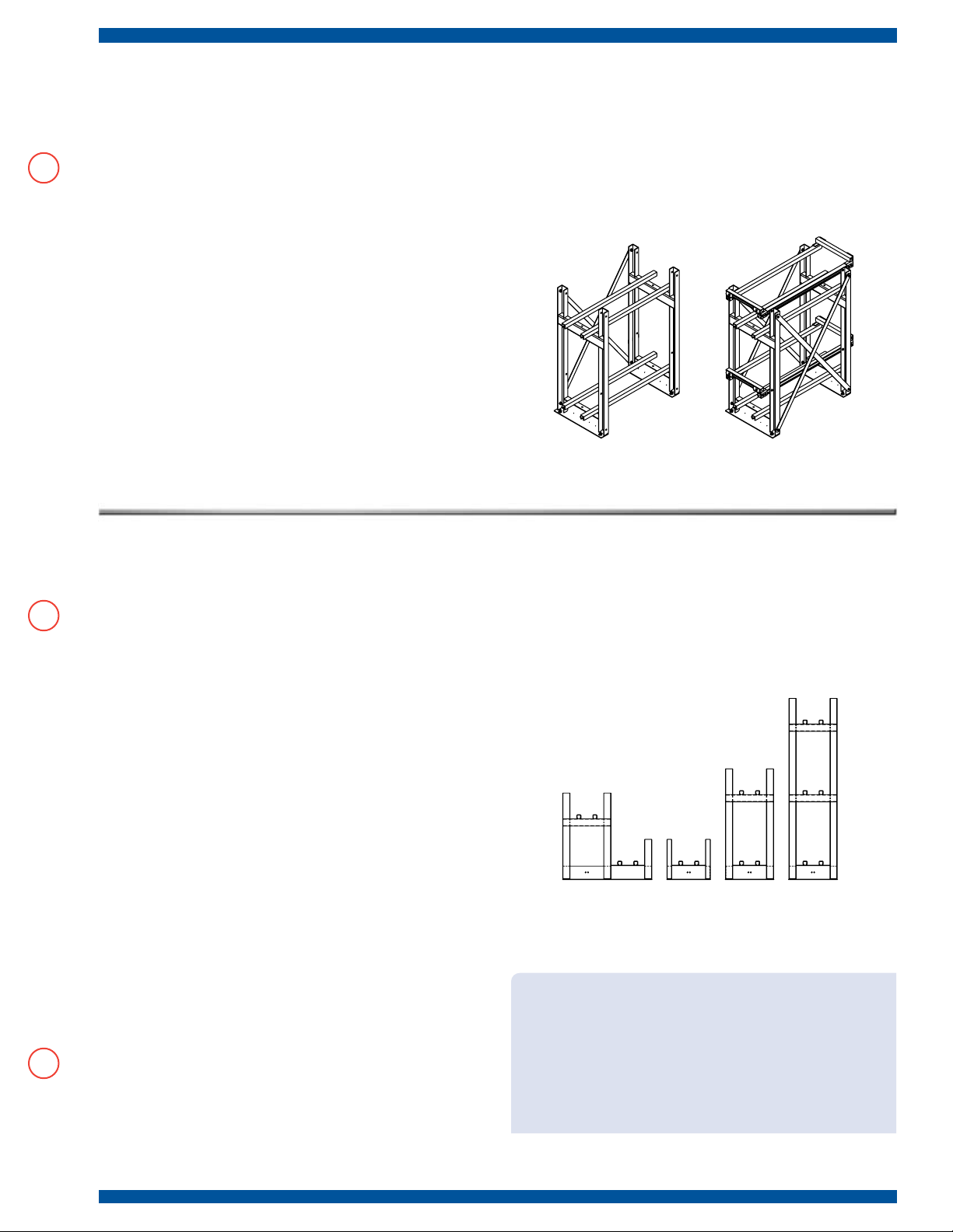
Two Tier Standard Rack Two Tier EP Rack
Figure 1. Standard Vs. EP Rack
Standard and Earthquake-Protected (EP) Racks:
Earthquake-protected racks are similar to standard racks, with
the exception of additional frame bracing, battery constraints and
spacer elements. Frames are the same for both Standard and EP
series. EP racks are certified to Section 1630 of the Uniform Building
Code, 1994 edition. See Figure 1.
Configuration:
Racks are available in single or multiple tier/step arrangements as
shown in Figure 2. Rack components are supplied loose and must
be assembled and secured on-site in accordance with these C&D
assembly instructions, the drawings included with the rack shipment,
and applicable codes.
Rack Location:
Locate racks in a clean, cool, dry place so the batteries are not affected
by sources of radiant heat, such as sunshine, heating units, radiators,
steam pipes, etc. Variations of more than 5 degrees F between cells
may cause the battery to become electrically unbalanced. Top rows of
batteries in multiple-tier configurations tend to operate at slightly higher
temperature than those on lower tiers. Always provide adequate
ceiling clearance for ventilation and maintenance.
Anchoring:
To provide stability, safety, and seismic integrity (for EP series),
racks must be securely anchored to the floor. Anchor bolts are to
be installed per contractor specifications and in accordance with
applicable codes. Do not attach rack to walls without consulting
C&D first. Mounting holes are provided in the base of each frame.
All frames must be secured to floor using all anchor bolt locations.
It is the responsibility of the customer to secure racks in accordance
with allowable floor loading, applicable codes and regulations.
Grounding:
Rack grounding provisions are integrated into the base of each
frame. Two through holes are located at the center of the frame’s
bottom cross member and may be used to secure a standard NEMA
lug. These holes are 0.44” in diameter and 1.0” between centers.
The surfaces surrounding the holes have been masked and are free
of powder coat to allow electrical contact. Frame to frame grounding
integrity is accomplished via the lower support rail, attached to each
frame with Internal/External “star” washers.
2-Step 1 Tier 2 Tier 3 Tier
Figure 2. Typical Rack Configurations
CAUTION:
• Donotinstallbatteriesuntiltherackhasbeenproperly
installed, with all bolts tightened to specified torque and
frames anchored to the floor.
• Donotuseoilorgreaseasalubricantforcellinstallation.
Lubrication is usually not required due to the low friction
interface of the insulating covers. If necessary, a small
amount of water or unscented talcum can be applied to
the rail covers to reduce friction.
Page 2
Assembly InstructIons for
stAndArd And eP rAcks
1 Material Verification : Battery racks are shipped
unassembled with a complete set of related drawings and
documentation. Check received parts and quantities against
the rack’s bill of materials on provided drawings and /or
packing list. Do not assemble rack if parts are missing or
quantities are incomplete.
2 Required Tools : Torque wrench (0 to 65 ft.-lb.) with 9/16”
and 3/4” Hex socket. Adjustable wrench or 9/16” and 3/4” box
wrenches, tape measure, square and leveling device.
Note: Consult manufacturer’s instructions for tools required to
install floor mounting hardware.
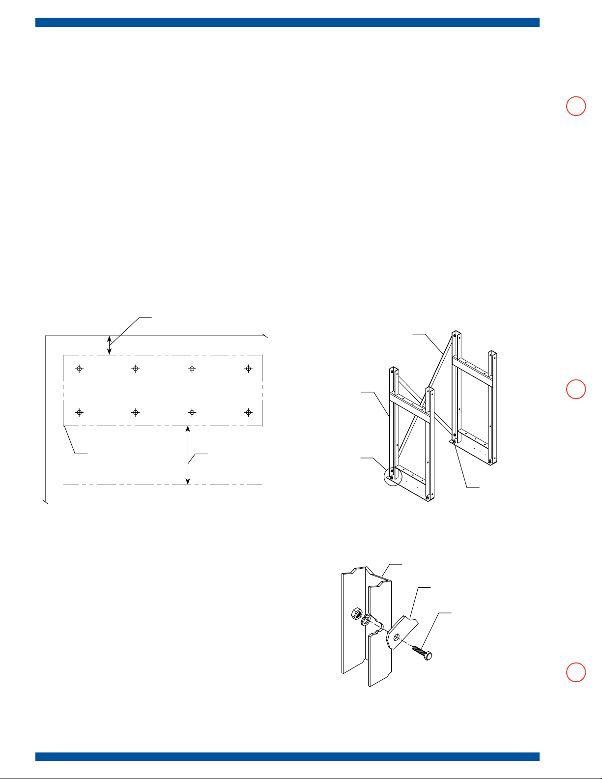
2” Typical Clearance Around
Existing Boundary
3 Location of Rack Assembly: When determining rack
location and floor bolt pat tern, use applicable drawings
provided with rack shipment. Locate the rack’s general position,
considering boundar y and aisle clearances. Locate floor
mounting locations using provided drawings. See Figure 3.
Note: Floor mounting hardware is to be determined in
accordance with applicable building codes, not by C& D.
4 Initial Assembly: Place frames over installed floor
mounting hardware, finger tight. (Hardware not supplied by
C&D). All frames must face the same direction. Install back
cross braces, finger tight. See Figure 4. Do not install front
cross braces at this time (if required).
Note: Cross bracing pattern along the length of the rack
may not necessarily be symmetric. Cross bracing pattern
and location(front, middle, or back) is detailed on assembly
drawing provided with the racks.
Cross Brace (s)
Frame
External Rack Dimensions.
See Assembly Drawing.
36” Typical Aisle
Clearance
Figure 3. Rack Assembly Location
and Anchor Bolt Pattern
Frame and Cross
Brace Connection.
See Detail 1.
Floor Mounting
Hardware
Figure 4. Initial Assembly
Frame Upright
Cross Brace
1/2-13 Bolt, Lock
Washer and Nut
Detail 1. Brace to Frame
connection ( Reverse View)
Page 3

Assembly InstructIons for
stAndArd And eP rAcks
9 Front Restraint Rail (EP only): With the batteries in
place, slide the front side support rail and cover up from its
resting location to its mounting location, aligning with rear
side restraint rail. Install hardware and torque to 15-20 ft.-lbs.
See Figure 8.
10 Final Assembly: Install corner brackets, end restraint rails,
and covers. Position end restraint rail against end battery unit.
See Detail 4. Note that the corner bracket may be reversed
by 180° if required. Install all front cross braces if indicated by
rack assembly drawing. Torque to 55-65 ft.-lbs. See Figure 9
for final rack assembly.
11 Battery Arrangement: Install inter-cell and inter-
unit connectors and cable assemblies as specified by
battery arrangement. Refer to Battery Installation Manual
(RS -1476) for more detail on battery connection and
initialization change.
Restraint Rails and
Figure 8. Installed Front Restraint Rail
End Restraint
Rail and Cover
Side Restraint
Rail and Cover
Cover (Installed)
Figure 9. Assembled EP Rack,
With Front Cross Braces
Corner
Bracket
3/ 8-16 Hex Bolt, Lock
Washer and Serrated Nut
Detail 4 . End Restraint Rail (s)
and Corner Brackets
Page 4

Assembly InstructIons for
stAndArd And eP rAcks (contInued)
5 Installing Support Rail(s): Place support rail(s) in
location using supplied 3/8” bolt, washer, serrated strut nut,
finger tight. Align support rails with “A” dimension from rack
assembly drawing. Install rail covers. See figure 5.
Note: An internal/external “star” washer is used in place of
lock washer on bottom tier or step, for grounding connection.
Optional third rail should be installed at this time (L-Series only).
Support Rail
and Cover
Rail to Frame
Connection.
See Detail 2.
6 Leveling: Check that the rack is level and square. Torque
down all bolts. First torque the cross brace bolts to 55-65 ft.-lb.,
then torque the rail to frame bolts to 15-20 ft.-lbs. Torque anchor
bolts to manufacturer’s recommended value.
Support Rail
Frame
and Cover
3/ 8-16 Hex Bolt,
Washer (Lock or star)
and Serrated Nut
Figure 5. Support Rail Installation
Detail 2 . Frame and Support Rail Connection
At this point, you have installed a C &D Standard Rack, please proceed to step 8 for cell installation or if you have
an EP Rack, continue on in this procedure.
Page 5

AdditionAl Assembly instructions
for eArthquAke Protected (eP) rAcks
7 EP Rack Assembly (Continued): Install all back
restraint rail(s) and cover(s). See Figure 6. If installing a
rack to hold either a JC or XTJ battery system, the provided
spacer block must be installed between the restraint rails and
the frame. See Detail 3. Position front restraint rail and cover
temporarily next to front support rail prior to installing cells. DJ
Series battery racks to utilize lower set of restraint rail holes to
avoid interference with the handles.
8 Cell Installation Procedure: If not instructed otherwise,
install cells starting at the center of the bottom row and,
working out to each end, leave a half inch space between
cells. For EP racks, use spacers between cells as supplied.
Back Restraint
Rail and Cover
Back Restraint
Rail to Frame
Connection.
See Detail 3.
Do not use oil or grease as lubricants. Instead a small
amount of water or unscented talcum may be applied to the
rail cover to help reduce friction. For rows having an odd
number of batteries, the center of the first battery installed
will match the center of the row. For rows having an even
number of batteries, a cell space will coincide with the center
of the row. Pay attention to polarities and terminal placement.
Refer to the battery’s Installation and Operating Instruction
manual for more details. All cells should be pushed back
against back restraint rail and cover. Up to 1/8” gap between
restraint rail and cells is acceptable. Repeat this procedure
for remaining steps and tiers, working upward. See Figure 7.
Battery Units
Figure 6. Initial Step For EP Rack
Back Restraint
Rail and Cover
1/2” Spacer
Block. Used for
“J” Series Only
Frame
Detail 3. Frame and Restraint Rail(s)
(Reverse View)
Front Restraint Rail
and Cover (loose)
Figure 7. Cell Installation
3/ 8-16 Hex Bolt,
Lock Washer and
Serrated Nut
Figure 7a. Cell Spacer Detail (L-Series)
Page 6

ADDITIONAL INSTRUCTIONS FOR
MULTI-RACK ARRANGEMENTS
Back to Back Assembly:
Where two rows of racks are required, two rack assemblies may be
installed in parallel front to back.
Frame Location:
Locate back to back frames relative to each other as shown, such
that the rear cross brace attachment holes align for the two adjoining
frames. All braces must be installed, as described previously, except
that a single bolt may be used to connect the front and rear frames
and respective cross braces. Use 3/16” spacers and/or washers to
ll gaps between adjacent frames. See gure 10.
Back of Racks A and BFront of Rack A
Front of Rack B
End to End Rack Installation Instructions:
Where a continuous rack string is required, two racks may be
installed adjacent in length.
Frame Location:
End to end rack assemblies are installed as two individual, standalone rack assemblies as shown. When installing standard racks,
the minimum clearance between racks is 0”. When installing EP
racks the two racks must be spaced apart so that the minimum
distance between the ends of the support rails is 5”. See Figure 11.
5” Min. Between
End to End EP Racks
Figure 10. Back to Back Assembly
1400 Union Meeting Road
P.O. Box 30 53 • Blue Bell, PA 19422-0858
(215) 619-2700 • Fax (215) 619-7899 • (800) 5 43-8630
customersvc@cdtechno.com
www.cdtechno.co m
Figure 11. End to End Installation
Any da ta, descr iptions or spe cificati ons presen ted herein ar e subject to re vision by C&D Tec hnologies , Inc. without no tice. While s uch inform ation is be lieved to be a ccurate a s indicat ed herein, C &D Technol ogies, Inc . makes
no war ranty and h ereby discl aims all warr anties, ex press or impl ied, with reg ard to the acc uracy or comp letenes s
of su ch infor mation. Furthe r, becaus e the p roduct (s) fea tured h erein ma y be us ed unde r condit ions bey ond its
cont rol, C&D Technol ogies, Inc. he reby disclai ms all warran ties, eithe r ex press or implie d, concern ing the fitnes s
or suit ability of s uch produ ct(s) fo r any parti cular use or in any speci fic applica tion or arisi ng from any c ourse of
deal ing or usage o f trade. Th e user is sole ly respons ible for det ermining th e suitabili ty of the pro duct(s ) featur ed
here in for user’ s intended p urpose an d in user’s sp ecific app lication.
Copy right 2007 C &D TECHN OLOGIES, I NC. Printed i n U.S.A. 12-3 34 5M/ 0107/TD /3
 Loading...