

Page 1
MSE
®
DCS
®
RS02109/0814/CD 1 ww w.cdtechno.com
Page 2

SAFETY PRECAUTIONS
Only authorized and trained personnel familiar with battery installation, preparation, charging, and
maintenance should be permitted access to the battery.
WARNING
SHOCK HAZARD – Do not touch un-insulated batter y, connectors or term inals. Be sur e
to discharge static electricity from tools and technician by touching a grounded surface
near the batteries, but away from the cells and flame arresters.
All tools should be adequately insulate d to avoid the possibility of shorting conn ec tions.
Do not lay tools on the top of the battery.
Although VRLA batteries are sealed and emit no gas during normal operation, they
contain potentially explosive gases, which may be released under abnormal operating
conditions, such as a charger malfunction. It is the responsibility of the customer to
provide adequate ventilation so hydrogen gas accumulation in the battery area does
not exceed two percent by volume. However, normal air circulation in a ventilated
facility will preclude any hydrogen build-up even during equalize charging. Never
install batteries in a sealed cabinet or enclosure. If you have any questions, contact your
local C&D representative.
This battery contains sulfuric acid, which can cause severe burns. In case of skin contact
with electrolyt e, r emove contaminated clothing and flush affected areas thoroughly with
water. If eye cont act has occurred, f lush for a minimum of 15 minutes with large amo unt s
of running water and seek immediate medical attention.
Warning
Risk of fire, explosion or burns. Do not disassemble, heat above 80ºC (175ºF) or incinerate
MPORTANT
NOTE
FOR ADDITIONAL INFORMATION CONTACT:
C&D Technologies, Inc.
Technical Service Department
1400 Union Meeting Road
P.O. Box 3053
Blue Bell, PA 19422-0858
Telephone 1-800-543-8630 +1 (215)619-2700 FAX 215-619-7899
customersvc@cdtechno.com
Check C&D’s web site for further details www.cdtechno.com
This manual is to be used for the ins tallation and operating of C&D’s Liberty MSE or Liberty DCS series of batteries.
RS02109/0814/CD 2 www.cdtechno.com
Page 3

Liberty 2V (Liberty MSE & Liberty DCS)
VALVE REGULATED LEA D-A CID BATTERIES
TECHNI CAL MANUAL
Table of Contents
Part 1 - Introduction .............................................................................................................................. 5
1.1 Cell Characteristics...................................................................................................................... 5
Part 2 - Recommended Technical References ................................................................................. 6
Part 3 - Safety Precautions ................................................................................................................. 7
3.1 Recommended Tool s .................................................................................................................. 7
3.2 Personal Protection Equipment (Safety) ...................................................................................... 7
3.3 Installation Equi pm ent, T ools and Sup pl i e s ................................................................................. 8
Part 4 - Receiving ................................................................................................................................ 8
4.1 Inspection at Time of Delivery ..................................................................................................... 8
4.2 Damage and Shortage Situations ................................................................................................ 8
Part 5 Storage ...................................................................................................................................... 9
5.1 Storage Conditions ...................................................................................................................... 9
5.2 Storage Temperature and Duration ............................................................................................. 9
Part 6 - Installation .............................................................................................................................. 9
6.1 Locating Battery System .............................................................................................................. 9
6.2 Ventilation .................................................................................................................................. 11
6.3 Floor Loading and Anchor i ng .................................................................................................... 11
6.4 Spill Containment ...................................................................................................................... 11
6.5 Electrical Connections ............................................................................................................... 11
6.6 Terminal Plates ......................................................................................................................... 12
6.7 Numbering Cells ........................................................................................................................ 12
6.8 Interconnection .......................................................................................................................... 12
6.9 Tap Connections ....................................................................................................................... 13
Part 7 - Initial Charging ..................................................................................................................... 14
7.1 Initial Charge ............................................................................................................................. 15
Table 1 – Charging Requirements ............................................................................................... 15
7.2 Initial Charge Records ............................................................................................................... 15
RS02109/0814/CD 3 www.cdtechno.com
Page 4

Liberty 2V (Liberty MSE & Liberty DCS)
VALVE REGULATED LEA D-A CID BATTERIES
TECHNI CAL MANUAL
Table of Contents
Part 8 - Battery Operation................................................................................................................. 17
8.1 Float Charging ........................................................................................................................... 17
8.2 Cycle Charging .......................................................................................................................... 17
8.3 Equalize or Freshening Charging .............................................................................................. 18
8.3.1 Equalize or Freshening Charge Float Charge Applications ................................................ 18
8.3.2 Equalize or Freshening Charge Cyclic Applications ............................................................ 18
8.4 Temperature Effects on Batteries .............................................................................................. 19
Part 9 – Maintenance ........................................................................................................................ 20
9.1 Monthly Inspection .................................................................................................................... 20
9.2 Quarterly .................................................................................................................................... 20
9.3 Semi-Annually ........................................................................................................................... 20
9.5 Performance Tests .................................................................................................................... 21
Part 10 - Battery Degradation ........................................................................................................... 21
10.1 General Information and Precautions ...................................................................................... 21
10.2 Float versus Cycle Life ............................................................................................................ 21
10.3 Low Float Voltage and Sulfation .............................................................................................. 22
10.4 Hydration ................................................................................................................................. 22
10.6 Parallel Battery Strings ............................................................................................................ 23
10.7 High Temperature Operation ................................................................................................... 23
Appendix............................................................................................................................................ 24
Appendix A – Installation of Modules .............................................................................................. 24
Appendix B - Termin al Connections ................................................................................................ 30
Appendix C – MSDS 14-355 Liberty MSE & Liberty DCS ............................................................... 31
Appendix D – Handling and Replacement of Individual Cells .......................................................... 31
Appendix E – Battery Inspection Report .......................................................................................... 33
Appendix F – Recycling ................................................................................................................... 35
RS02109/0814/CD 4 www.cdtechno.com
Page 5

Part 1 - Introduction
The Libert y 2V batt eri es (Li bert y MSE or L ibert y DCS) r efer ence d in th is docum ent ar e stat io nary,
lead-acid batteries. They are constructed with an absorbent glass mat (AGM) and are charact er ized as
Valve Regulated Lead-Ac id (VR LA). As VRL A, t here is no free flowing electrolyte. They are constructed
with lead-calcium alloy grids, dilute sulfuric acid (electrolyte) enclosed in a flame retardant thermoplastic
container (non-flame retardant container also available) with a safety vent and a flame arresting disk to
prohibit a spark from entering the head space of the cell. This type of battery is nearly 100% recyclable.
At the end of life, please dispose of properly or consult C&D for recycling information.
The Liberty 2V batteries are designed to provide reliable service life with minimal maintenance when
used in accor danc e wit h this manual. They are a single cell unit producing a nominal two volts per
cell, which are connected in series for the desired system voltage. The cells are housed in steel modules,
coated with acid resistant paint. These modules come in varying heights, depending on the cell size
and two widths (3 cells wide and 4 cells wide), and can be stacked up to 84” high while maintaining
their seismic ratin gs.
The Liberty 2V series are to be inst alled in a horizontal position with al l connections accessible from the
front of the system assembly. These cells are not designed for operation in any other orientation.
The Liberty MSE series is designed for float operation with minimal cycling. Typical applications include
Telecom, Switchgear/Control and other non-UPS applications which are subjected to 20 or fewer cycles
per year.
The Liberty DCS series is designed for cycling applications. Typical applications include OffGrid/Unreliable grid Telecom, Renewable energy or other stationary applications requiring a high number
of cycles throughout the life of the cell.
1.1 Cell Characteristics
Under normal float operation, Liberty 2V batteries can be installed in proximity to electronic equipment
and in computer rooms with occupied space. However, if subjected to excessive overcharge voltage,
hydrogen and oxygen can be vented into the atmos phere. Therefor e, lea d ac id batt eri es sho uld
never be installed in an airtight enclosure. Sufficient precautions must be take n to pre vent
excessive overcharge and containment of potential explosive off gases. All Lead-Acid batteries,
including Liberty 2V, are capable of generating excessive potentially explosive gases when charged for
prolonged periods at voltages higher than initial or equalizing charge. The Liberty 2V cells are equipped
with a “flash arrestor and pres sure r elief valv e” assem bly th at se als the c el ls dur ing norm al charge
and operation but allows it to safely vent in case of overcharge. Removing the valve assembly can
cause th e r ele as e of po te nt i al ly explosive gases and such action will void the warranty.
RS02109/0814/CD 5 www.cdtechno.com
Page 6

Part 2 - Recommended Technical References
These instructions assume a certain level of competence by the installer/user. Installers must have the
appropriate knowledge and experie nce to safely install the batteries. The design of the battery room, system wiring,
protect ion, e n vir onm ent al , f ir e, a nd s af et y r eq uir em ent s m ust c om pl y with applicable codes required by the
governing enforcement agency.
The following is a partial list of the codes that may have direct impact on your installation. This list is not meant to
be comprehensive. Consult with your local building, electrical and fire protection agencies to get proper direction
to the local codes that will affect your installation.
• NEC National Electric Safety Code, ANSI C2-1993 (or latest revision)
• UBC Uniform Building Code or locally applied Building Code
• IBC International Building Code
Federal Codes that may directly affect your battery room design and battery installation.
• 29CFR1926.441 Safety Requirements for Special Equipment
• 29CFR1910.151(c) Medical Services and First Aid
• 29CFR1 910.268(g) Telecommunications
• 29CFR1910.305(j) Wiring Methods, Components and Equipment
• STD 1-8.2(e) OSHA Standing Directive
The following references to IEEE documents contain relevant information. They should be consulted for safe
handling, installation, testing, and maintaining standby batteries. You may also refer to the battery brochure for
additional information, specific to the battery.
• IEEE 1187 “Recommended Practice for Design and Installation of Valve-Reg ulat ed Lea d-Acid
Storage Bat ter ies for Stationary Applications”
• IEEE 1188 “Recommended Practice for Maintenance, Testing, and Replacement of Valve-Regulated
Lead-Acid (VRLA) Batteries for Stationary Application”
• IEEE 1189 “Guide for Selection of Valve-Regulated Lead-Acid (VRLA) Batteries for Stationary
Application”
• IEEE 1375 “Guide for Protection of Stationary Battery Systems”
• IEEE 1491 “Guide for Selection and Use of Battery Monitoring Equipment in Stationary
Applications”
• IEEE P1578 “Guide for Battery Spill Containment”
Copies may be obtained by contacting:
The Institute of Elec t rical and Electronic Engineer s (IEEE), Inc. IEEE
Customer Service
445 Hoes Lane
PO Box 1331
Piscataway, NJ 08855-1331
customer.service@ieee.org
or visit the IEEE web site: www.standards.ieee.org
RS02109/0814/CD 6 www.cdtechno.com
Page 7
Part 3 - Safety Precautions
This batter y is de sign ed for in dust ri al, stat io nar y use only and is not intended for application in
vehicular, starting, lighting and ignition (SLI), and the operation of portable tools and appliances.
Use in accord ance with this manual or al l I EEE battery procedures. Use of this product other than in
accordance with these instructions may produce hazardous and unsafe operating conditions, leading to
damage of equipment and/or personal injury.
Do not expose the batteries to open flame or electrical arc. Do not tamper with the vent, as this will
void the warranty.
Do not use any petroleum based cleaning or lubrication solution on the battery jar or cover. Failure to
follow this warning may result in damage to the container and will void the warranty.
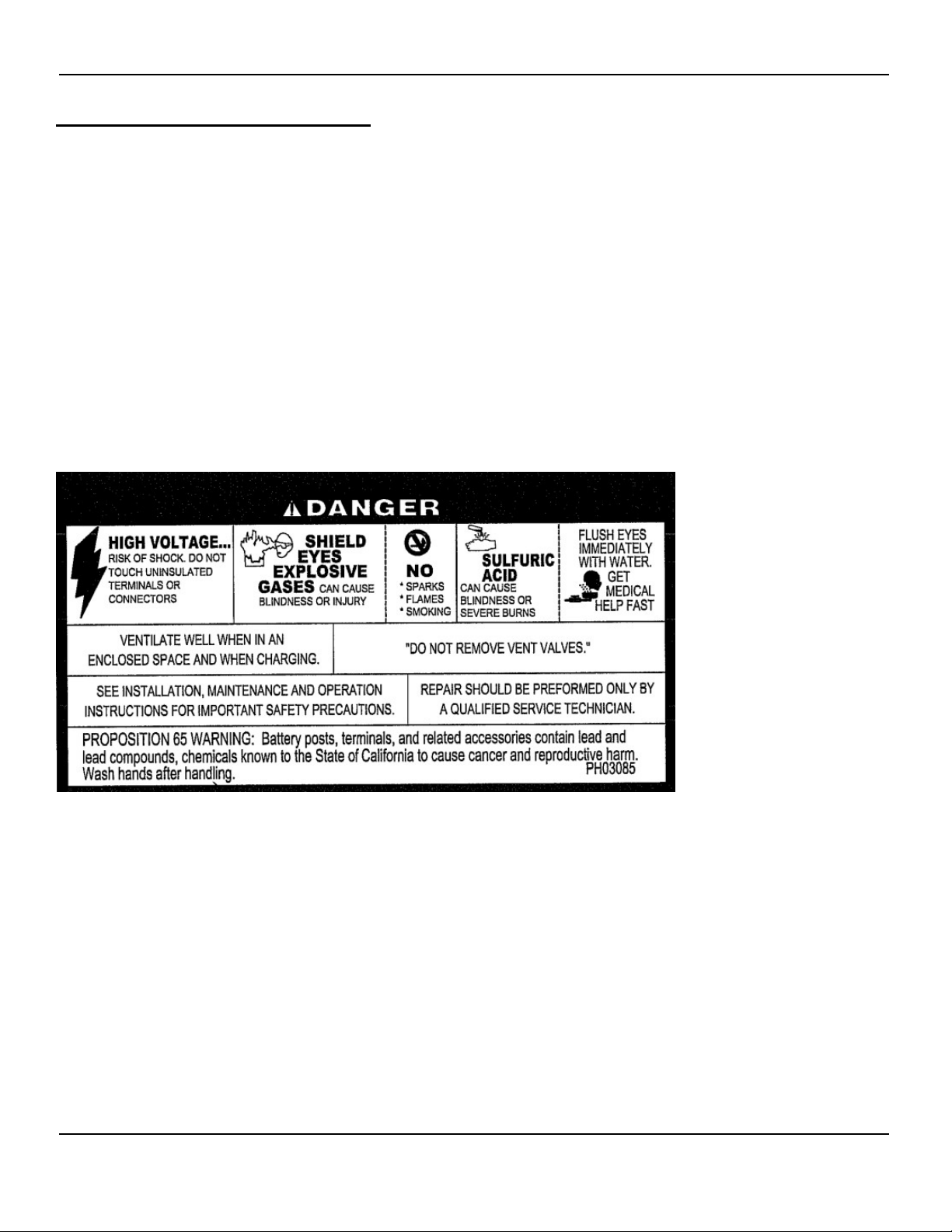
As a notice to all technicians and personnel in the near proximity of the batteries, a BCI warning label is
in plain view to indicate the potential hazards of battery systems.
Figure 1 - BCI warn in g label
3.1 Recommended Tools
The below lists are general recommendation and is not intended as a complete and specific list. Each
installation may require specia l tools that cannot be identified without knowing the specific applications.
Review the appropriate industry recommendations, state and local codes for the specific information.
3.2 Personal Protecti on E quipment (Safety)
• Use standard battery safety practices
• Rubber or Neoprene – Acid Resistant Gloves
• Protective apron
• Face shield/safety glasses or ANSI approved goggles
• Rubber soled safety shoes/boots
• Portable or permanent eye wash station
RS02109/0814/CD 7 www.cdtechno.com
Page 8

3.3 Installation Equipm e nt , Tools and Supplies
• Lifting sling or appropriately sized platform – for lifting cells into modules or modules into position.
• Fork lift or portable crane.
• Insulated steel toed safety shoes & remove all metals, i.e. rings, etc – to ensure no short circuits.
• Bicarbonate of soda, 1 lb per gallon of water – to neutralize and clean up any electrolyte.
• Metric insulated tools – to ensure no short circuits between connections.
• Insulated torque wrench – to ensure no short circuits between connections.
• Digital voltmeter with three – digits and 0.25% accuracy minimum – to record initial cell open circuit
voltages & ensure correct assembly.
• Digital Micro-Ohm meter (DLRO) – to measure connection resistances.
• Optional, one of the following; res ist ance, conductanc e or impedance meter – to r ecord initial
ohmic measurement s .
• Non-metallic brush or pad for cleaning connections – to ensure clean connections for good integrity.
• NO-OX-ID grease and applicator brush – to ensure good connection integrity throughout service life.
• Minimum of (2) lifting straps (lifting capacity 500 lbs + each).
Part 4 - Receiving
4.1 Inspection at Time of Delivery
Great care has been taken to pack the battery for shipment to ensure its safe arrival. As soon as you
receive the battery, check the packing m ate r ia l f or evi d en ce of dam ag e in t r ans it. I f the packing mater ia l is
physically damaged or wet acid stains are present, make a notation on the delivery receipt before you accept
the shipment/delivery.
NOTE:
Freight Carriers generally require that the carriers’
representative inspect concealed damage within 10 days
from date of delivery to determine responsibility.
The resolution of such claims may extend up to nine months.
Verify the number of cartons and skids against the bill of lading and verify their contents against the
packing l ists. K eep a cop y of the ver if ied l ists for your i nsta llat io n recor ds. It is impor ta nt to co nfirm that
the accessory package is pr ese n t a nd th e qua nt i t ie s ar e cor r ec t. If he lp is req u ir ed, c al l C &D c ust om er
service dep art m en t t o re p ort any discrepancies.
4.2 Damage and Shortage Situat ions
C&D ships FOB Pharr, TX (zip code 78577) (title/ownership passes to the ship-to/end user at t h e Pha rr , T X
warehouse ) . If s h ipm ent s ar e d amaged or if cartons or skids are damaged or missing, a claim must be filed
with the carrier. Plac e an immediate order f or replacement with C&D. P ay both the original invoice and the
replacement invoice using th e replacement cost as t he amount of freight dam ages or shortages involved as part
of your claim. If individual component items are missing, a shortage report should be filed within
30-days fr om the dat e of rec ei ving a sh ipment with C&D customer service department. Mail (express mail
recommended), e-mail customersvc@cdtechno.com
component-packing list. This verified list should show both the name of the packer, as well as the quantities
of items checked off by the receiver.
, call 1-800-543-8630 or fax a copy of the VERIFIED
RS02109/0814/CD 8 www.cdtechno.com
Page 9

Part 5 Storage
5.1 Storage Conditions
Store batteries indoors in a cool, well ventilated, clean, dry location and place in service as soon as possible
after receiving.
5.2 Storage Temperat ure and Duration
The recommended temperat ure for stor age is 50°F (10°C) to 77°F (25°C). Liberty 2V cells may be
stored at these temperatures f or approxim atel y si x months; longer storage is detrimental to t he cell
and can void the warranty if they are not given a freshening charge within that time period. A convenient
measurement to check the condition of the cell d uri ng st or ag e i s t o me as ure t he O p en C ir cu it Vol tag e
(OCV). A fully charged Liberty 2V c el l has an appr oxi mate O CV of 2.1 6 volt s. If th e Li bert y 2V series
cell OCV dr ops m or e t han 0. 0 4 v olts f r om its rec ei ve d v olt ag e or measures less than 2. 12 vo lts , a
freshening charge is required. Be sure to record dates and conditions (voltage, current and recharge
times) for all charges during storage.
Avoid exposure of a partially discharged cell to temperatures less than 0.0°F (-18°C), as this may
cause the battery electrolyte to freeze. This can permanently damage the battery and can cause potentially
hazardous leakage.
Higher than normal storage temperature (77°F [25°C] nominal) will accelerate internal self-discharg e of a
cell by a factor of two for each 15°F (10°C) over nominal 77°F (25°C) storage temper ature. This, in
turn, will reduce th e al lowable tim e befor e init ia l and/ or boost charging.
If a freshening char ge is required, it is very important that boost or freshening c harges (2.35 v/c for 12
to 16 hours) be gi ven at the appropriate t im e t o avoid major remedial action or loss of product as noted
in Part 7.
Part 6 - Installation
6.1 Locating Battery System
Install the batteries in a clean, cool, and dry location. Avoid areas with direct sunlight and heat sourc es,
including electrical equi pment vents or exhausts. The recommend ed batt er y room tem perat ur e of
77°F (25°C) provides the best combination of performance and life. Lower temperatures will reduce
battery performance, while higher temperatures will improve battery performance but reduce battery
service life.
Avoid sources of hot or cold air that could cause temperature variations of ±5°F (3°C) within th e
battery assembly. Such variations will compr om ise o pt imum bat t er y p erfo r m ance s uc h as t h e f l oat
voltages of individual cells.
For additional information on installing batteries in modular systems, refer to the Appendix for installation
details.
RS02109/0814/CD 9 www.cdtechno.com
Page 10
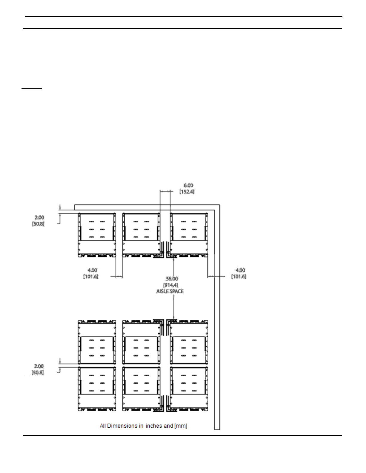
When considering room layouts and determining the necessary floor space required for mounting a given
system the below diagram is a guide to C&D’s recommended system clearances. Should a question or
concern arise please contact your C&D sales representative for further details. Each system is shipped with
an Applications Engineering System layout which goes into further detail on system layouts and floor
anchoring.
Notes:
1. Allow a minimum of 2.00” from the back of any system to a wall or any other obstruction/equipment.
2. Allow a minimum of 4.00” between systems (side to side) where no side termination is being used.
Reference supplied C&D connection diagram for additional details.
3. Allow a minimum of 6.00” between systems (side to side) where side termination is being used.
4. Allow a minimum of 4.00” spacing from any wall/equipment to the side of any system.
5. When installing systems back to back allow a minimum of 2.00” spacing from module to module as
shown in the diagram below.
6. Always allow for a minimum of 36.00” aisle space in front of the system for suitable handling
equipment.
7. There may be a de-rating of anchor bolt load ratings due to the proximity of anchor holes. Reference
anchor bolt manufacturer’s data for additional information.
RS02109/0814/CD 10 www.cdtechno.com
Page 11

•
•
•
•
•
6.2 Ventilation
Although the Liberty 2V bat teries ar e valve r egul ated, t hey can produce minimal gas emis s ion s d ur ing
normal operation. If exposed to abnormal high voltage charging, the cells may vent potentially explosive
hydrogen gas. Hy drogen gas when accumu lat ed in a c onfined area t hat exce e ds f our (4% ) p er cen t b y
volume in air is explosive. C&D recommends not allowing hydrogen gasses of greater than one (1%)
percent b y vo lume to a cc um ul ate. C ontact the loc al c o de enforcement off icer t o determine what codes and
levels are applicable to your battery room installatio n. Lead acid batteries should never be installed in a
sealed, non-ventilated cabinet or enclosure.
VRLA batteries subjected to extreme overcharge voltages have the potential to relea se h ydr oge n g as at a rat e
of 0.0 002 6 9 cu b ic f eet pe r m i nut e per ampere of charging current at 77°F (25°C). The Liberty 2V series
testing shows that they re c omb in e at near ly 99% effi cienc y und er nor mal conditions. However, compliance
with appropriate safety measures regarding hydrogen evolution is essential for the safety of the equipment
and personnel.
6.3 Floor Loading and Anchori ng
Floor loading and anchoring requirements are the responsibility of the user/installer and all applicable
building codes and regu lations must be follo wed. C&D provides connection drawings, weights, dimensions,
and floor loading information on our system drawings for reference which is supplied with every shipment.
The Liberty 2V floor-mounting base has provisions f or floor anchoring. Consult the applicable building codes
and regulations for specific requirements. In all cases, floor anchoring is considered mandatory with
floor anchors to be installed in all l ocations provide d unless otherwise specified. Floor anchor sizing
and hardware are the responsibil ity of the user/installer.
6.4 Spill Containment
Although t he Lib erty 2V batteries contain no free flowing electrolyte, it is the sole responsibility of the
user/installer to follow all local building and fire codes applicable to the battery installation. It is
recommended consulting the local fire marshal or building inspector to determine if spill containment
is required.
6.5 Electrical Connections
WARNING:
Always use protective ins ulating equipment, such as gloves, shoes, eye and
face protection. Wrenches and other tools must be properly insulated.
Observe local, state, and national electric codes at all times. Always work with the battery
ungrounded. Battery ground connections, if required, should be made last.
To avoid working with high voltages, brea k the battery down into convenient
lower-voltage modules, equal to or less than 48-volts.
Always maintain a firm grasp on tools and hardware when working on the battery.
Dropped hardware can cause a short cir cuit, possibl y resulting i n serious pers onal
injury and/or damage to the equipment.
Before working on the battery, be sure to discharge static electricity that can build
up on tools or the technician by touching a grounded surface in the vicinity of the battery.
RS02109/0814/CD 11 www.cdtechno.com
Page 12
6.6 Terminal Plates (If part of the battery system)
For reasons of safety, it is r ecom m ende d t h at t er m in a l plates be insta l led bef ore connector
install at ion as des cr i be d i n se ct io n 6.8. Interco nn ect c el ls an d m odu l es wit h t in-plated (standard)
copper connectors and 6mm stainless steel hex head bolts and washers in accordance with the
connection diagram supplied with each battery shipment.
Prior to installation, lightly brush (with a plastic brush or burlap) the battery terminals and terminal plate
contact surfaces. Then apply a thin coating of NO-OX-ID type grease. The Liberty 2V battery terminals
are made of a brass alloy with a tin coating cast inside a lead terminal. Terminal plates are made of
copper with a thin tin coating. Once coated with protective NO-OX-ID type grease, any “exposed”, “untinned” areas, no matter if from the factory or due to over brushing, will be protected from oxidation by
the grease thus not require reworking. Optional: preheat the NO-OX-ID type grease and apply warm.
After working with any lead component, wash your hands.
6.7 Numbering Cells
For ease of identification and for record keeping, all cells of a battery should be numbered. Plastic
peel-and-stick numbers are furnished in the ac cess ory k it. Comm on pr acti ce is to sta rt wit h “1” on t he
cover of the incoming (+) positive ter minal of t he batter y and follow the e lectr ical c ircuit with
succeeding numbers on the cell covers.
6.8 Interconnection
Cell series connection is made from the (+) of one cell to the (-) of the next sequential cell. I t is essent ial
that the cell locat ion and orient ation match the included drawing. All connections must be made as
indicated on the drawing with no deviations. If no drawing is provided or it is lost, contact C&D before
making any connections.
The cells ship with NO-OX-ID grease applied by the factory to the terminals, however it may be
necessary to rework prior to connecting the cells with the supplied inter-cell connectors. Refer to t he
Appendix for additional instructions for reapplying NO-OX-ID grease.
Prior to installation, lightly brush (with a plastic brush or burlap) the battery terminals and any contact
surfaces of the inter-unit connections. Then apply a thin coating of NO-OX-ID type grease to both the
battery terminals and contact surfaces of the inter-unit connectors prior to installation. The Liberty 2V
battery terminals are made of a brass alloy with a thin tin coating cast inside a lead terminal. The interunit connectors (cables and bus bars) are made of copper and have a thin lead or tin coating. Once
coated with protective NO-OX-ID type grease, any “exposed”, “un-tinned” coated areas, no matter if from
the factory or due to over brushing, will be protected from oxidation by the grease thus not require
reworking. Optional: preheat the NO-OX-ID type grease and apply warm. After working with any lead
component, wash your hands.
RS02109/0814/CD 12 www.cdtechno.com
Page 13

The top r ow of c on nectors is to b e i nst a ll ed first, then t he s e co nd row down and so on, work ing from the
top down. W hen inst all ing con nec tors, install the top (upper most) bolt first. Complete connector installation
by torquing all connections t o 110 in-lb. [12.4 N-m ] , using an insulated torque-wrench.
NOTE:
Over-torquing can damage the post seal
and degrade connection integrity.
After torquing all connections and with the bat ter y still o n open cir cuit (not connected to the charging
source), take post-to-post resistance measurem ents. Start at one e nd of the str ing and work to the ot her
end, recording micro-ohm resistance of e ach i nte r-cell connection betw een cell s. Clean and re-torque
connections (see Appendix B) of similar size connectors which exceed ±10% percent of the average resistance
of battery connections or five micro-ohms, whichever is greater.
IMPORTANT:
Record and retain the resistance readings with the
initial charge information for future reference. See Appendix E.
CAUTION:
It is the sole responsibility of the user to check connections.
Never operate a battery with loose or corroded connections.
When checking connections, disconnect the battery from the load and the charging equipment
and follow a ll th e precautionar y me asur es outlined above and in the general safety references.
Some resistance measur em ent eq ui pm en t ma y c a use a s par k wh en t he pr ob es ar e a pp li ed t o t he
cell posts. Use appropriate safety precautions when conducting this measurement.
Typical cell and connection resistance values are provided in the Appendix according to cell type. In
addition, a listing of short circuit current in amperes is provided to further inform the user of the potential energy
available from these batteries.
After connecting all cells of the battery, check the battery voltage using a calibrated digital DC
voltmeter with at least three digits and 0.25% accuracy minimum. Battery voltage should equal
the open circuit voltage of an indi vidu al cell multi plie d by the n umber of cell s in the battery.
Example: (24 cells) x (2.16 VPC) = 51.84 OCV. If the OCV does not equa l the expect ed value, i nspect the
sequence of (+) to (-) connection s. Furt her investi gat ion ma y requi re re-inspecting each cell voltage
to confirm an acceptable value.
6.9 Tap Connections
Tap connections may electrically unbalance the battery system and may void the warranty. If a
center tap is used, each side must have its own charging unit.
RS02109/0814/CD 13 www.cdtechno.com
Page 14

Part 7 - Initial Charging
General Information and Precautions
To safely charge the Liberty 2V batteries and avoid damaging the battery and/or connected equipment,
observe the following:
• Use a constant voltage charger with only direct current (DC). AC ripple current from charger
shall not exceed (5%) of the 8-hour (ampere-hour) rating of the battery.
• Be sure charger is turned off before making electrical connections between the battery and system.
• Connect via the appropriate size cable. Verify polarity with a volt meter before making final charger
connections and turning on the charger.
• Be certain that al l connections are tig ht and secured before t urning on the charger.
The recommended method of providing an initial/freshening charge (section 5.2 and section 7.1 & 7.2) is to
first determine the maximum allowable voltag e that may be appl ied by t h e c onn ect ed eq u ipm ent .
Divide this by the number of cells in the battery to obtain maximum average voltage per cell allowed
by the equipment. Adjust this number to a recommended value found in Table 1 and continue charging at
this voltage.
NOTE:
Charging current to the battery should be limited based on the Ampere Hour capacity
of the battery. Refer to Table 1 for maximum charging current. Higher charging current
can cause overheating that subsequently increases the internal resistance of the battery,
which requires additional current to compensate for the increased internal resistance.
This cycle is referred to as “thermal runaway”, which has the potential to destroy the
battery and cause damage to equipment.
RS02109/0814/CD 14 www.cdtechno.com
Page 15

Time
Amps per 100Ah
Not
7.1 Initial Ch a rge
All cells are shipped fully charged f r om the factor y with no need f or an in itial f res hening or eq ualizat ion
charge. The cells should be constant voltag e c harg ed at t he average f loat voltages as noted in T able 1
below. However , when in stor age or transit f or an extended per iod (espe cia lly at temperatures above
77°F/25°C) or when the number of cells is g reater than 24 cel ls; it is rec omm ended the batt ery system be
given an initial freshening charg e (see Table 1) at instal lation.
Table 1 – Charging Requirem e nt s
Cell
Type
Liberty MSE 2.25 to 2.30
Liberty DCS 2.25 to 2.30 2.4 to 2.45
Average String
Float Voltage
77°F (25 °C)
VPC VPC VPC Hours
Average String
Cycle Service
Voltage 77°F
(25°C)
Recommended
Notes:
a. Battery float voltage should be set at Table 1 average cell voltage multiplied by the number of cells in the battery string.
Individual cell float voltages may vary by +0.10/-0.05 volts from the average in a single string.
b. Average string float voltage must be adjusted based on temperatures which are above or below 77°F (25°C) - see section 8.4.
c. Charging time will vary due to temperature if cell temperature is below 60°F (16°C), double the charge time for initial or equalize charge.
d. If a battery load test will be performed within 90 days of installation, an initial freshening charge followed by a 72 hour float charge
(per IEEE 1187) is required to ensure full capacity.
Average String
Freshening
Voltage
2.35 +/- 0.02 12 – 16 25
2.35 to 2.40
+/- 0.02
Freshening /
Equalization
Charging
12 – 24 30
Maximum Charge
battery rating
Current
7.2 Initial Charge Records
At the completion of the initial charge and after the cells have been on float charge for approximately one week,
record voltages of the individual cells, the total battery voltage and ambient temperature. Retain this
information in your files for future reference. This information establishes a baseline for future reference.
The information b elow must be recorded or ref er to RS-1992 found in the Appendix E. Make a photocopy of
the form and use it whenever necessary to record readings taken on the battery.
RS02109/0814/CD 15 www.cdtechno.com
Page 16

Battery identifications
1. Date of readings
2. Battery total float voltage
3. Ambient operating temperature
4. Date and description of initial or last equalizing charge
5. General observations from visual inspection
6. Individual cell voltages
7. Connection resistance measurement
9. *Optional: One of the following for cell ohmic testers:
Impedance, Conductance or Resistance
10. Name of inspection technician
If you observe any unusual readings or visual indications, consult your C&D Technologies
Represent at ive and s end a cop y of your lat est maintenance report to your local C&D Representative
or the technical services department at C&D.
*Cell ohmic readings may vary by ±20% of the C&D Technologies published values. This variation does
not necessarily indicate a problem with the condition of the battery.
IMPORTANT:
Initial charge records are essential for review by C&D
Technology’s sales/service representatives in the event of a
problem. Since records can materially affect your warranty, be
sure to maintain clear, signed, and dated copies.
RS02109/0814/CD 16 www.cdtechno.com
Page 17

Part 8 - Battery Operation
8.1 Float Charging
Standby batteries are connected to control circuits, which must be energized at all times.
Liberty MSE 2V batteries must be cons tant volt ag e charg ed as descr ibed in section 7. Connect ed t o a
load in parallel with a continuou sl y oper ati ng power supp ly, th ese bat teri es as sure inst anta neo us
support of the load in the event of a power failure or brownout. In addition to operating the
connected load, the power supply keeps the standby battery fully charged. This parallel interconnection
and operation is called float service. Maximum battery life can be expected in full float service, in which
the frequency and depth of discharges are kept at a minimum. Deep and/or frequent discharges can
shorten service life, even with proper battery maintenance.
8.2 Cycle Charging
Note: Numerous cycle charge algorithms are permissible with the 2V Liberty DCS cells and if the specific
charge algorithm is not explicitly stated in this manual please contact your C&D technical representative for
further information.
Cycling applications are the most demanding applications that lead acid batteries are subjected. In many
cases, the batteries are in a constant state of either being charged or discharged. Knowing how the system
operates is critical to understanding how the batteries should be charged.
In typical conditions, the battery is fully charged after every discharge cycle. Under these circumstances, the
battery will be brought back to full charge using a charging rate designed to bring the batteries back to full
charge before the next discharge. If the system cannot achieve a full charge between discharging cycles, or if
the system is being utilized in a PSoC operation, then additional charging needs to be employed to bring it
back to full charge at least once month. The charging system should be capable of automatically adjusting the
charging voltage based on the temperature of the battery. The measurement of the battery temperature must
be taken at the battery; not ambient temperature. Please see section 8.4 for additional information.
In float applications with deep or frequent discharges, battery service life can be maximized by following
recommended cycle charge voltages and currents as shown in Table 1 (Section 7.1). The 2V Liberty DCS
cells can be both constant voltage and constant current charged, provided a voltage limitation is set at the
values recommended in Table 1 (Section 7.1). In addition, partial state of charge operation (PSoC) is
permissible if state of charge regulation is provided or periodic equalization charging is utilized (see section
8.3).
In pure cycle applications, where the battery is either in discharge, recharge, or open circuit stand, with the
depth of discharge (DoD) ranging from 5-90%, either a constant voltage charge algorithm or a constant current
charge algorithm is permissible, provided a voltage limitation is provided. Voltage and current limits provided
in Table 1 (Section 7.1) should be utilized to ensure maximum service life. Pure cycle applications will also
require a periodic equalization or freshening charge, depending on the time between discharge cycles.
Generally bi-weekly or monthly equalization charging is adequate for most applications including PSoC
applications where the average state of charge is between 30-90% SoC. Equalization charging, for cyclic
applications, should follow the procedures outlined in section 8.3.2
RS02109/0814/CD 17 www.cdtechno.com
Page 18

8.3 Equalize or Freshening Charging
8.3.1 Equalize or Freshening Charge Float Charge Applications
Under normal float charge operating conditions, it is not necessary to equalize or freshen the Liberty
2V batteries when used within the criteria described in sections 5.2 and 7.
NOTE:
Some hydrogen gas may be liberated
at equalize charging voltage.
An equalizing charge should be performed if individual cell voltages fall 0.05 volts below the average float
voltage as specified in Table 1 (Section 7.1). Presence of a minimum voltage does not imply a battery is
malfunctioning or that it will not provide the necessary power when called upon.
NOTE:
Charging current to the battery should be limited based on the Ampere Hour capacity of the battery.
Refer to Table 1 for maximum charging current.Higher charging current could potentially destroy the
battery by overheating that subsequentlycauses more current to flow creating a cycle sometimes
referred to as “thermal runaway”.
8.3.2 Equalize or Freshening Charge Cyclic Applications
In cycle charge applications, depending on how the system is designed
the batteries are regularly discharged and regularly re-charged. In these applications, the charging system
should be sized so that, on the average, the battery is returned to between 85 to 90% state of charge daily.
On a bi-weekly to monthly basis the battery should be charged to 100% or fully charged state using the
equalization parameters outline in Table 1 (Section 7.1) for equalization/freshening charge for 2V Libert y DCS.
If the system is a solar-only system then the charging strategy is solely based on the photovoltaic panels
returning all of the energy to the battery every day. The ratio to the photovoltaic array to the load during the
worst conditions should be able to bring the batteries to full charge at least once a month.
If the system is a hybrid system where there is dispatchable battery charging capability, the batteries should
be charged to between 85 and 90% of full charge on a daily basis (daily charge). Monthly they should be given
an equalization charge to insure that they were fully charged and the SoC is reset.
NOTE:
Use the equalize voltage setting as shown in Table 1 (Section 7.1) for a period not exceeding the
specified hours depending on service conditions.
Consult your C&D Technologies Representative for additional information.
RS02109/0814/CD 18 www.cdtechno.com
Page 19

8.4 Temperature Effects on Batteries
C&D recommends that the battery be operated at 77°F (25°C) ± 10°F (5.5° C). F or ambi ent t empera tur es
outside th e recom men ded tem pera tur e rang e, the f loat vo ltag e must be adj u sted b y 2mV per °F or 3 .6mV
per °C. Adjust as indicated below.
Add 2mV (0.00 2 volt s) per °F or 3.6m V per °C be low 7 7°F (25 °C). Subtract 2m V ( 0.002 volts) per °F or
3.6mV per °C above 77°F (25°C).
If the bat ter y i s op er ated a t te mp er at ur es be lo w t he r ec om me nde d r ange, the capacity will be reduced
even with temperature compensated charging, which must be accounted for during initial system sizing.
RS02109/0814/CD 19 www.cdtechno.com
Page 20

Initial Torque
Maintenance Re-Torque
Terminal Connectors
110 in-lbs (12.4 N-m)
110 in-lbs (12.4 N-m)
Module to Module Bolts
40 ft-lbs (55 N-m)
40 ft-lbs (55 N-m)
Restraint Bolts
40 ft-lbs (55 N-m)
40 ft-lbs (55 N-m)
Part 9 – Maintenance
9.1 Monthly Inspection
The Liberty 2V battery is a VRLA cell which does not require water addition and no spec if ic g ra vi t ie s or
water leve ls nee d to be check ed thr oug hout its lif e. Ho wever , it is r ecomm end ed to prop er ly fol low th e
below maintenance procedure, to assure that the batteries are well maintained and ready for oper ation
when needed. A blank inspection report is shown in Appendix E.
1. Visual inspection of the battery for general appearance and connector conditions. Check for
bulging jars, corrosion build up or any signs of heat damage to the jars/covers and connectors.
2. Measure and record the total system float voltage.
3. Measure and record the total system float current.
9.2 Quarterly (including the above)
4. Optional; measure and recor d one of the follo wing ohmic measurement: conductanc e, impedance,
resistance or internal resistance of each b att er y. Changes over t ime of less t han ±20 % are acceptable,
changes of greater than 50 % require further attention (such as a load test).
5. Measure and record the temperature of the negative terminal on each cell.
9.3 Semi-Annually (including the above)
6. Measure and record the individual cell voltages.
9.4 Annually (including the above)
7. Torque cell bolts to 110in-lbs (12.4 N-m). Any disassembled connections should be retorqued to
110 in-lb (12.4 N-m).
8. Measure and record connector resistance reading. If a value exceeds the average by 10% for
similar connections, see Appendix B and reference IEEE 1188 for more information.
9. If possible, measure and record the total and individual AC ripple current or voltage.
Clean products with a solution of 1 lb of bicarbonate soda to 1 gallon of water, if necessary
For more information, IEEE 1188 discusses the significance of connection integrity, further maintenance
techniques, and testing information.
RS02109/0814/CD 20 www.cdtechno.com
CAUTION:
Never use solvents to clean a battery system. Only use a
solution of water and bicarbonate soda, 1 gallon to 1 lb.
Page 21

9.5 Performance Tests
If desired by the customer, a full-load performance test can be conducted at the user’s original specified
discharge rate or the appropriate rate based on connector sizing per the following procedure:
• Equalize charge the batteries if necessary, refer to section 8.3 equalization notes.
• Let batteries float for 72-hours.
• Perform the annual inspection.
• Run a discharge test at the system designed rate per IEEE 1188.
Part 10 - Battery Degradation
10.1 General Information and Precautions
When properly maintained and charged, the Liberty 2V batteries should provide many years of trouble-free
service. H owe ve r, de spit e t he ir in h er ent dep e ndab i li t y, f ai lur e t o o p er ate and m a i nta in t h em c orr ectly can
lead to damage, shortened service life and possible loss of service. The following sections address some of
the most frequently encountered errors.
10.2 Float versus Cycle Life
Standby batteries such as the Liberty MSE are designed and constructed to provide long life in
continuo us f l oat s er vic e. They differ i n th eir d es ign f r om th e 2 V Li b ert y D CS cy cl ing batteries. Standby
batteries are conti nuous ly cha rge d at a comp arat ive ly lo w float vo ltag e in par al lel with the lo ad, ready to
supply instantaneous DC power either d irectly to the load or by way of interfacing electronics, such as an
uninterruptible power supply (UPS) system. T he name “stat ionary” impl ies the batt ery is usually
permanent ly p laced i n a give n loc atio n and not tr ansf err ed fr om place to place in its service life.
As such, standby battery life is directly affected by and will be degraded if subjected to r epe at ed cycling.
Depth of dis ch arg e, number of discharges, rate of discharge, and the interval between discharges are all
determin i ng f act or s in bat t er y lif e. C yc li ng s h ou ld t her ef or e b e k ept to a minimum. To ensure that the battery
will perform during power outages and other emergencies, it i s str ongly recomm ende d t h at t est i ng b e k e pt t o
a minimum in accordance with the following practices:
• The performance of an initial acceptance test not to exceed user’s originally specified system
reserve time.
• A full-load service test should be performed not more than once every 12 months to verify battery
capacity at user’s originally specified discharge rate.
• A monthly transfer test not to exceed 30 sec onds of bat tery dis ch arge time at us er ’s or ig i nal ly
specified discharge rate to verify system load transfer and electrical system perf or mance.
The time that is required to synchronize the UPS and return to rectifier power must be taken into
account when calculating total discharge.
The user is expected to maintain complete records of all battery testing and emergency discharges in
order to comply with the requirements of the warranty.
RS02109/0814/CD 21 www.cdtechno.com
Page 22

Liberty DCS cells are specifically designed for cycle service and while their robust design allows them to be
used in numerous types of cycle applications from mild shallow DoD service to continuous PSoC service,
battery service life can be maximized by following recommended cycle charge voltages and currents as shown
in Table 1 (Section 7.1). In addition, following recommended equalization charging procedures, temperature
compensation guidelines and maintaining accurate SoC and DoD limitations will ensure the Liberty DCS cells
provide long and reliable cycle service.
CAUTION:
RECHARGE BATTERIES AS SOON AS POSSIBLE AFTER
AN EMERGENCY DISCHARGE. Failure to recharge batteries
immediately after emergency discharge may lead to sulfation,
or in the case of deep discharge, a complete battery failure
due to hydration. If recharging at freshening/equalize voltage
is impractical, promptly recharge at float voltage.
10.3 Low Float Voltage and Sul fat ion
Either because of incorrect charger voltage adjustment, excessive intermittent or static loads paralleling
the charging source, low operating temperature or simply not fully recharged; a battery may not receive
adequate charging voltage. In some cases, the charger m ay eve n be turne d off , erro neous ly or by
choice. The n et res ult i s a batter y lef t in a part iall y dis char ged or under charg ed condit io n. The first
observable signs may be errat ic cell voltag es. A lthoug h not vis ible to t he observer, the plates will
become sulfated.
If you suspect sulfated plates, contact the C&D Technical Services Department 1-800-543-8630 or
(+1) 215-619-2700 for assistance. Sulfated batteries are not fully charged batteries t hus have not
completed the electrochemical reaction of recharge. Accordingly, they will have reduced capability. If
allowed to remain in a partially charged condition for an extended pe r iod of t im e, su lf at e d bat t er ies m a y
suffer irreversible damage, requiring replacement.
10.4 Hydration
A battery t hat has been severely over-discharged and left in a discharged condition without immediate
recharge is subject to damage known as hydration. This is a phenomenon in which the electrolyte specific
gravity has been reduced to a value so low it permits the lead components to dissolve into the
electrolyte.
The reaction of dissolution forms many compounds and salts, generically referred to as hydrate.
On recharge these compounds react to c log separat or pores and form metallic lead. As time passes
thousands of short circuit paths are created in the separators placed between the positive and negative plates
to provide electrical insulation. Very often, the effect of these shor t cir cuits goes u nnot ice d except for a
slight increase in charging current. As the reaction continues, however, short circuits become so extensive it is
almost impossible to keep the cells charged. Finally, the cells experience t otal failure. Liberty 2V batteries
are more resistant to hydration than t ypical wet cells, larg ely because of th e thic k absor bent g lass mat
separator b etwee n the pl ates. Howe ver, in severe cases of hydration, internal short circuits can form.
RS02109/0814/CD 22 www.cdtechno.com
Page 23

10.5 Open Circuit – Late Installations
As soon as a batte ry is di sco nnect ed fr om a charg er, local acti on (self-discharge) beg in s . This is caused by
inherent intern al losses within the cell. In the case of Liberty 2V cells , a self-discharge is expected to occ ur at
a rate of “up to 3.0 percent” of full charge per month at 77°F (25°C). Therefore, if cells remain, for whatever
reason, on open circuit (with no charge supplied) for prolonged periods of time, the affected cells may become
sulfated and require corrective action in the form of a freshening charge, see Sections 5.2, 7.1 & 7.2.
10.6 Parallel Battery Strings
When strings of batteries of equal voltage are connected in parallel, the overall capacity is equal to the sum
of the cap ac it ie s of the ind ivi d ua l st r ing s. W hen p ar a ll el ing val ve-regulate d batt eri es is ne cess ary, t he
external circuit resistance should be matched for each battery. A wide variation in battery circuit resistance can
result in unbalanced discharge (i.e., excessive discharge currents in some batteries and less discharge in
others). As a consequence, cell failures in one battery string and the subsequent loss of performance
capacities of that string will res ult in h igh er loads in the l ower resis tance inter con nect io ns of some parallel
strings that may exceed the ratings of the battery interconnections and/or cables. C&D recommen ds
paralleling strings to obtain higher capacity, to increase system reliability and with properly installed
disconnects, perform maintenance on one string at a time.
10.7 High Temperature Operation
Operating a battery at temperatures exceeding 77°F (25°C) will reduce the battery life.
Elevated temperatures accelerate the electrochemical reaction with i n t he lea d a c id b att er y.
For additional information, refer back to Section 8.4.
RS02109/0814/CD 23 www.cdtechno.com
Page 24
shipping materials are removed unbolt the system from the shipping pallet.
never tilt module forward.
Figure A2
Figure A4
Figure A5
Appendix
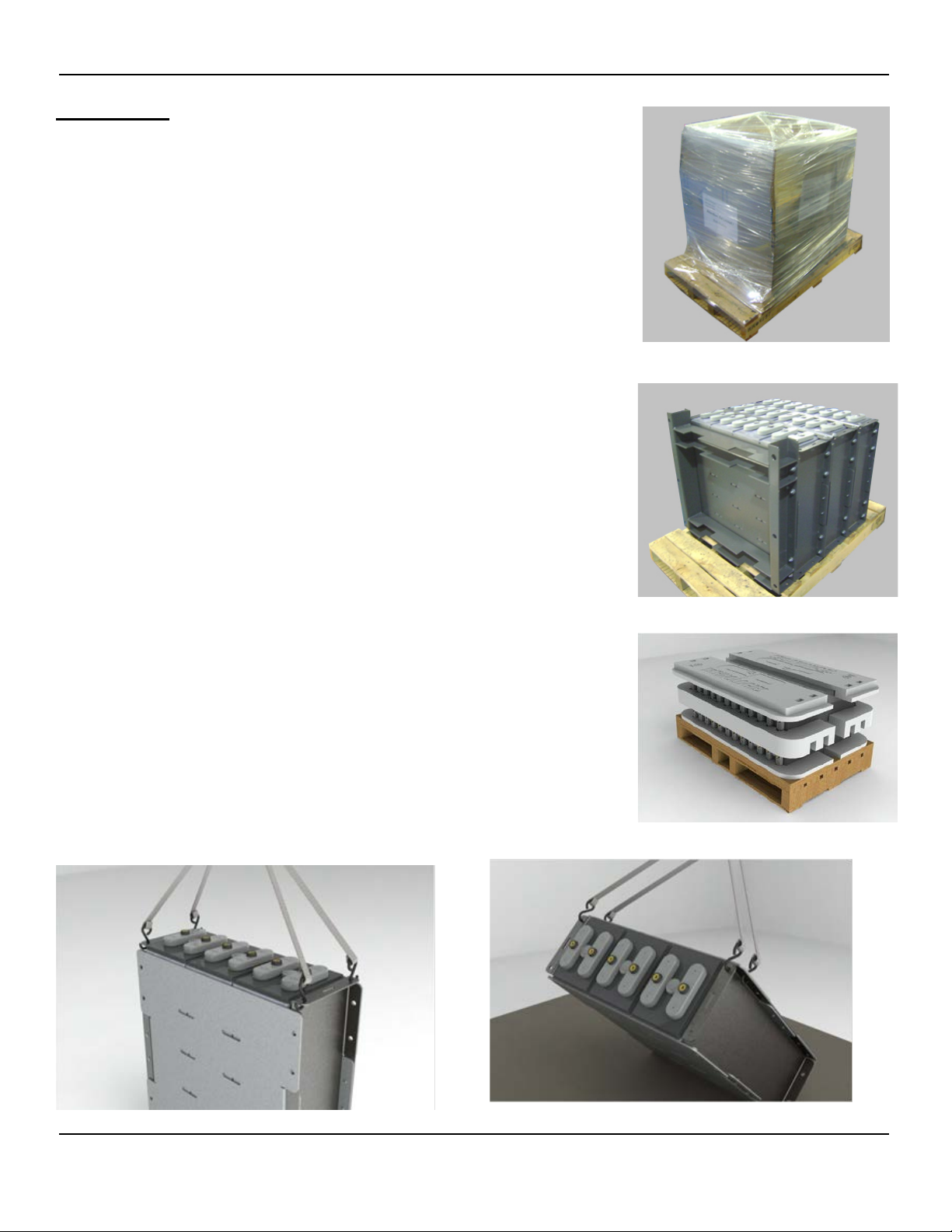
Appendix A – Installation of Modules
The Liberty 2V battery systems can be shipp ed with t he cells insta lled
into the modules or separately. Modules with cells installed are stacked
vertically and bolted to pallets for ease of transportation (See Figure A1 &
A2). When cells are packed separate l y they are packaged in foam for
safe transport and installed into mo dules on site (See Figure A3). It is
essential and the r esponsibility of t he c ustomer/installer to be properly
trained and have suitable equipment to handle these heavy products. It is
the responsibility of the customer/ inst all er to pro vid e a room pro per ly
designed for a batt ery system , inc lud ing appr opr iat e vent ila tio n, aisl e
space, eg re ss , f lo or load capabilities and a level mounting surface.
Unpacking and Handling
Do not remove shipping materials if a storage period is expected. The
battery modules are shipped in varying groups depending on cell size.
Lag bolts are used to attach the modules to the pallet along with a
protective honeycomb hood, cardboard packaging and shrink wrap
(See Figure A1).
Carefully remove all shipping materials and dispose of properly. Once all
Figure A1
Each system will be provided with one base assembly (See Figure A2) for
floor anchoring and should be removed first followed by any other bolted
connection leaving only the module rivets (See Figure A4, A5). The
design of the module allows for handling by a fork lift, portable crane or by
a battery lift table. When handling modules it is very important to use a
piece of insulating material such as shipping cardboard, plywood or rubber
insulating mat between handling equipment & battery terminals. Always
verify the lifting capacity of the equipment being used and never lift more
than one module at a time. Always use both lifting straps in an “X” pattern
as shown throughout this manual. The module assembly can be lifted by
either the front flanges or by a combination of holes on both flanges (See
Figure A4, A5 & A9). CAUTION: Cells are tightly fit however not
completely restrained until system is completely assembled therefore
Figure A3
RS02109/0814/CD 24 www.cdtechno.com
Page 25
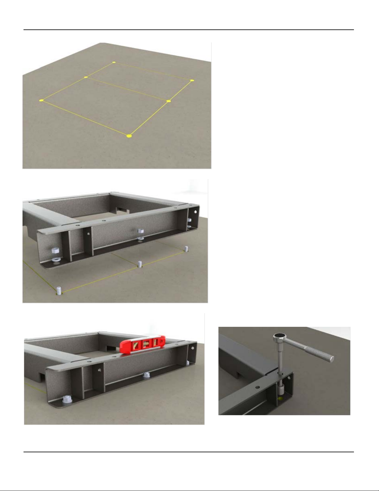
Figure A6
Floor Anchoring
Figure A7
Figure A8
Floor loading and anchoring requirements
are the responsibility of the user/installer
and all applicable building codes and
regulations must be follo wed. C&D
provides connection drawings, weights,
dimensions, and floor loading information
on our system drawings for reference
which is supplied with every shipment.
Anchor bolts are the responsibility of the
user/installer and are not supplied with the
order.
1. Where floor anchoring is required, place
base assembly into position an d ma r k
the anchor locations using the b ase as
a templat e ( See Figure A6 & A7).
2. Six 13/ 16” [20.6m m] ho les are
provided in the system base for floor
anchoring.
3. Inst al l f lo or an chors and repos it i on
base onto anchors (See Figure A8).
4. Install anchor hardware and verify top
surface of b as e assembly is le vel in
both axes, if ne ces sar y in sta ll shim s t o
level base.
5. Once base assembly is level, torque
anchors to proper rating based on
manufactures specification. (See Fig ure
A8).
6. A level base is particu lar ly import ant
for the stability and safety of high,
narrow stacks.
If tool clearance is an issue rear anchors can be accessed
using a standard 3/8” extension as shown.
RS02109/0814/CD 25 www.cdtechno.com
Page 26

Module Stacking/System Assembly
Figure A9
Figure A10
With base prope rly ins t al led, modules
unpackaged and in the horizontal position,
locate the C& D is s ued system diagram to
verify prop er c ell orientation wh en stacking
modules.
C&D recommends the following two methods for
handling Liberty 2V modules.
1. Portable Crane/Fork lift:
In the case of limited access in the rear of the
module install only the (4) 10mm bolts in the
rear flanges prior to hoisting. Connect optional
lifting straps in a “X” pattern as shown and
hoist carefully.
Note: Depending on the battery type some
sagging may occur while lifting however once
released and in position will return to square
(See Figure A9).
2. Battery Lift Table:
Again prior to hoisting, install only the (4)
10mm bolts in the rear flanges. Verify module
orientat i on then position mod ule on lift table
keeping metal surfaces isolated from battery
terminals. The modules flat top and bo tt om
surfaces allow it to easily slide from the lift
platform to the base with little effort (See
Figure A10).
Note: When lifting battery modules always
verify the lifting capacity of the equipment
being used and ne v er lift more than one
module at a time.
3. Next, make only the lower tier module to base
connections using (8) 10mm bolts (4/side).
Torque to 40 ft-lb [55N*m].
Note: Only the Module – to – Base connection
requires the use of all (8) bolt connections
(See Figure A11).
Figure A11
RS02109/0814/CD 26 www.cdtechno.com
Page 27

Module Stacking/System Assembly
Figure A13
Figure A12
(Tiers 2 and higher)
1. Using either of the two lifting methods
described on the previous sheet continue
with stacking modules for tiers (2) on up.
As mentioned before it is always a good
practice to reference C&D connection
diagram while stacking modules to assure
proper cell orientation. Doing so can save
time and effort in the future if a module is
installed in the incorrect orientation.
2. Once the module is in positi on and bolt
holes are in alignment make the Modu l e –
to – Module connecti on using (4) 10mm
bolts (2/side) in t he horizontal pla ne.
Torque to 40 ft-lb [55 N*m].
(See Figure A14).
3. Follow these steps for an y additional
modules for tiers 2 on up.
Note: Modu le – to – Module connection on l y
requires the use of (4) bolt connections per
tier in the horizontal plane (See Figure A14).
Figure A14
RS02109/0814/CD 27 www.cdtechno.com
Page 28

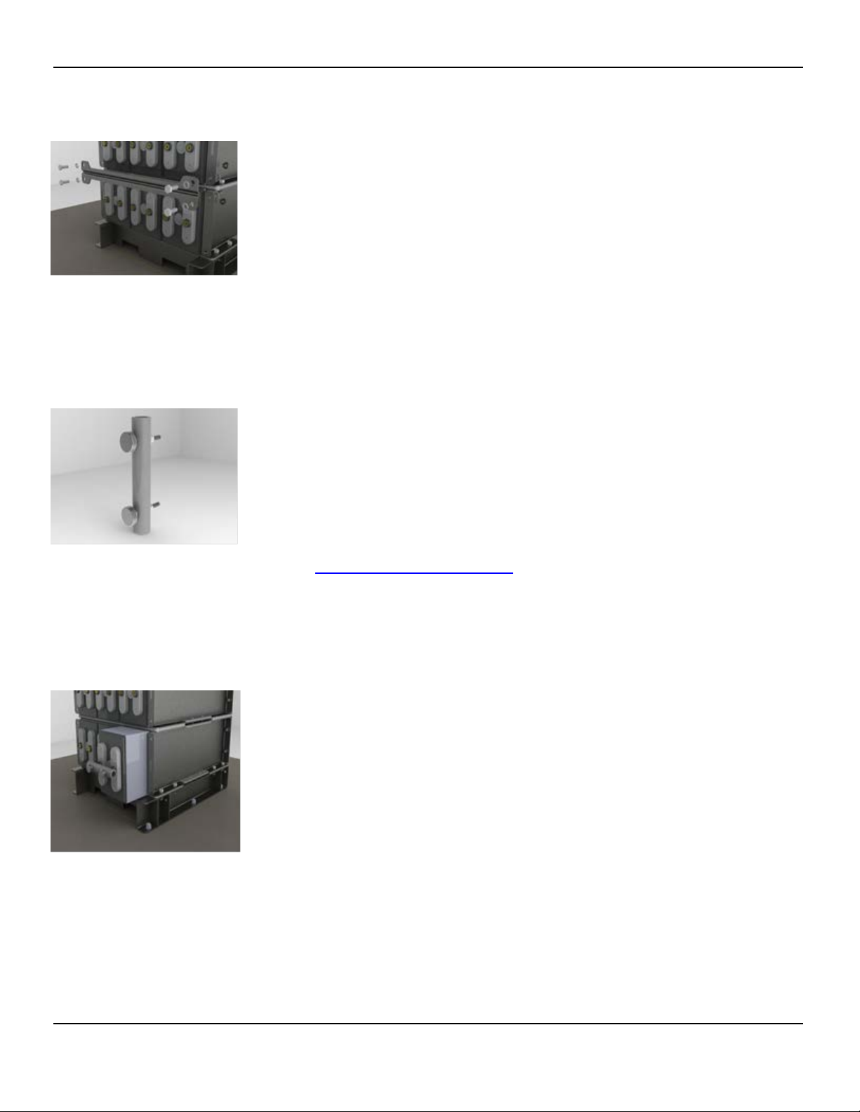
System Restraints
Figure A16
Figure A17
Figure A15
All systems are supplied from the factory with
two types of restraints. These restraints are
critical in maintaining the seismic rating of the
system and must be installed properly.
Front Restraint
Front restraints are installed between each
tier of the system to prevent cells from
shifting in the event of an earthquake. With all
of the modules properly stacked and in
agreement with the C&D layout drawing
attach the restraint bar using (4) 10mm bolt
assemblies (See Figure A15).
Top Restraint
Each system/stack will be supplied with one
top restraint. The top restraint will be installed
on the upper most module to complete the
assembly. The restraint will be installed using
(6) 10mm bolt assemblies (See Figure A16).
Final Check
Once the top restraint is attached the system
assembly is complete. Before attaching
terminal plates and making series
connections verify one last time the cell
orientation matches the supplied C&D
connection diagram.
Refer to Section 6 for mounting Terminal
Plates & inter-cell connectors.
RS02109/0814/CD 28 www.cdtechno.com
Page 29

Stack Module Disassembly and Re-assembly Procedure
If a requirement to disassemble and re-assemble a module stack arises, follow the following procedure.
1. Starting with the uppermost module in the stack, remove the individual cells following the
instructions shown in Appendix D.
2. Repeat until all the cells have been removed.
3. Disassemble the stack modules. Transport the bottom stack module to the desired
installation location. Mark the location of the floor anchors and install, again matching the
anchor holes in the floor-mounting base.
4. Be sure the floor mounting base or assembly is in position and level, and then t or q ue t h e
floor anc hors. If the bas e is not l eve l, use sh ims to level. A level base is particularly
important for t he s t ability and safety of these high, narrow stacks (See Figure A8).
5.
If the assembly requires additional modules, use the lifting slings. Place additional
modules, one at a time, on top of modules already in place. Properly align modules and
mounting ho les, and insert the M10 bolts, washers and nuts as shown in Figures A7 and
A8. When all bolts are in place, check that assembly is plumb and level, then tighten the bolts
to 40 ft-lb (55 N-m) using a torque wrench.
6. Reinstall the cells starting with the bottom module and working up. Perform the electrical
connections last.
RS02109/0814/CD 29 www.cdtechno.com
Page 30

Appendix B - Terminal Connecti ons
1. Remove any remaining factory-applied grease coating from the terminals with a
dry cloth.
2. Lightly brush the terminal, cable lug, terminal plates and cont act surfaces with a plastic brush or
burlap.
3. Coat all electrical surfaces with NO-OX-ID grease. (Optional: Use heat gun or hot plate to melt and
then apply the NO-OX-ID grease, no open flames).
4. (Optional) - Re-flow excess NO-OX-ID with heat gun and wipe excess.
5. Install hardware and torque to 110 in. lb. (12.4 N-m).
6. Wash hands after working with lead.
Reworking Terminal Connections: If a terminal connection needs to be reworked (for any reason)
follow the below steps:
Once the battery string has been removed from service using properly insulated tools and all appropriate
battery safety methods remove the suspect connection(s).
1. Remove any existing grease using a dry cloth.
2. With a neutralizing solution consisting of one-pound baking soda mixed with one
gallon of water, wipe the cover and term inal seal area with a cloth moistened with the neutralizing
solution. Do not allow the neutralizing solution to enter the cell. Rinse with clear water and dry
thoroughly.
3. Lightly brush the terminal, cable lug or terminal plate contact surfaces with a plastic brush or
burlap, removing any oxidized or corroded areas.
Note: Liberty 2V batteries terminals, buss bars, cable lugs and terminal plates are made of copper and
have a thin layer of tin. Once the terminal connection is coated with protective NO-OX-ID type grease,
any “exposed”, or “un-tined” areas, no matter if from the factory or due to over brushing, will be protected
from oxidation by the grease and not require reworking. Optional: preheat the NO-OX-ID type grease and
apply warm. After working with any lead component, wash your hands.
4. Coat all electrical surfaces with NO-OX-ID grease. (Optional: Use heat gun or hot plate to melt
and then apply the NO-OX-ID grease, no open flames).
5. (Optional) - Re-flow excess NO-OX-ID grease with heat gun and wipe excess.
Re-Install hardware and torque to 110 in. lb. (12.4 N-m) and measure connection resistance.
If still > +10% consult C&D.
RS02109/0814/CD 30 www.cdtechno.com
Page 31

Appendix C – MSDS Documentation
For the most up to date MSDS information, please visit the C&D Technologies public website.
Public Website - www.cdtechno.com
MSDS Sheets - http://cdtechno.com/resource/msds.html
RS02109/0814/CD 31 www.cdtechno.com
Page 32
Appendix D – Handling and Replacement of Individual Cells
A key design feature of the Liberty 2V battery is the provision for servicing
individual cells. With a minimum amount of handling and downtime, individual
cells can be changed in the field. In addition, disassembly and reassembly of the stack modules may accom moda te instal lation of a new
battery if necessitated by a hard-to-access location. Once the battery string
has been removed from service, the technician must use properly insulated
tools and adhere to all appropriate battery safety methods.
Figure D1
Figure D2
Figure D3
1. Remove the connector covers from the subject module.
2. Disconnect the system ground connection.
3. For each connector attached to the cell, loosen (but do not remove) the
terminal bolts at either end.
4. While holding the connector in one hand, remove the terminal bolts
completely. Remove the connector and set aside. Repeat for other
connectors.
5. After performing the electrical preparation described above, the steps to
physically remove the cell or cells can be performed as follows.
6. Remove cell retaining bar, shown in Figure D1.
7. Attac h the “cell puller tool ” , part number RE05259. This tool , sh own in
Figure D2, is available from your local C&D Technologies
Representative or directly through C&D Customer Service.
(customersvc@cdtechno.com
)
8. Prepare for cell removal by moving a platform lift or equivalent lifting
apparatus in pro ximity to the bottom of the stack module fr om which
the cell is to be removed. Make sure all exposed metal on the platform
is insulated. Verify the capacity of the lifting apparatus is sufficient to
safely lif t t he c e ll. I MP OR TA NT: B ef ore rem o vi ng t he c el l, note the
orientation of the cell in the module, i.e., positive terminal up or down.
9. Pull the cell straight out onto the platform, shown in Figure D3.
10. Follow Steps 2, 3 and 4 in reverse order to physically install the
replacement cell or reinstall a new disassembled battery. Do not perform
the electrical connections at this time.
11. Note: There is also a connection drawing supplied with each battery that
will aid in c ell orientation and installation. When all cells for a given
module have been installed, reinstall the cell-retaining bar.
12. Perform terminal and connector preparation.
13. Perform polarity check.
14. Reinstall connections.
15. Re-install connector covers.
16. Note: Liberty 2V cells should never be lifted by the terminals. Do not use
the cell puller tool as a lifting device
17. Never remove more than one cell per tier at a time.
RS02109/0814/CD 32 www.cdtechno.com
Page 33

RS-1992
APPENDIX E
BATTERY INSPECTION REPORT
TECHNICAL SERVICE DEPARTMENT Inspection by:
1400 UNION MEETING ROAD
BLUE BELL, PA 19422 Date of Inspection:
User's Name: Authorized Site Contact:
Installation Location:
Phone Number:
Other:
System OEM: Installation by:
C&D Order #
C&D Ship Date: Positive Posts:
Date Installed:
Battery Model: Negative Posts:
Cells X Strings:
Application:
Cell Covers:
Bus Voltage, Portable
Meter:
Bus Voltage,
Equipment, Final:
Presence of Lubricant on
cells?
Yes No
Charger Size:
Charger Type:
Charger Serial #:
Charger Mfg:
Ambient Room
Temperature
Last Discharge:
Peak Load Current
Amp. Or KW
Typical Load
Current/KW
Cell Arrangement:
Appearance of Following Battery Items
BATTERY & CHARGER SYSTEM INFORMATION
C&D TECHNOLOGIES' 2-VOLT BATTERY AND CHARGER INSPECTION REPORT
COMMENTS AND RECOMMENDATIONS:
Appendix E – Battery Inspection Re port
RS02109/0814/CD 33 www.cdtechno.com
Page 34

RS-1992
BATTERY CHARGE STATUS Open Circuit Float Equalize
BATTERY BUS VOLTAGE Vdc Vdc Vdc
LOCATION:
Cell #
Volts
+2.000
Serial #
Connection
Resistance
Internal Cell
Conductance/
Impedance/
Resistance
Cell #
Volts
+2.000
Serial #
Connection
Resistance
Internal Cell
Conductance/
Impedance/
Resistance
RS02109/0814/CD 34 www.cdtechno.com
Page 35

Appendix F – Recycling
Lead-acid batteries are recyclable and C&D Technologies currently has a low cost, convenient, and
environmentally safe collection and recycling program. Visit the C&D Web site at www.cdtechno.com
further information.
for
RS02109/0814/CD 35 www.cdtechno.com
Page 36

RS02109/0814/CD 36 www.cdtechno.com
Page 37

RS02109/0814/CD 37 www.cdtechno.com
Page 38

Any data, descriptions or specifications presented herein are s ubject to revision
Copyright 2011 C&D TECHNOLOGIES, INC. Printed in U.S.A. RS02109 0714/CD
by C&D Technologies, Inc. without notice. While such information is believed to
1400 Union Meeting Road
P.O. Box 3053 | Blue Bell, PA 19422-0858
(215) 619-2700 | (800) 543 – 8630
Fax (215) 619-7899
customersvc@cdtechno.com
www.cdtechno.com
be accurate as indicated herein, C&D Technologies, Inc. makes no warranty and
hereby disclaims all warranties, express or implied, with regard to the accuracy or
completeness of such information. Further, because the product(s) featured
herein may be used under conditions beyond its control, C&D T echnologies, I nc.
hereby disclaims all warranties, either express or implied, concerning the fit ness
or suitability of such product(s) for any particular use or i n any specif ic appl ication
or arising from any course of dealing or usage of trade. The user is solely
responsible for determining the suitability of the product(s) featured herein for
user’s intended purpose and in user’s specific application.
RS02109/0814/CD 38 www.cdtechno.com
 Loading...