

Page 1
Valve-Regulated Lead Acid Batteries
Installation and Operating Manual
RS02044/1114/CD 1 www.cdtechno.com
Page 2

incorpor at e d herein or a written copy is provided within the shipping materials
SAFETY PRECAUTIONS
Only authorized and trained personnel familiar with battery installation, preparation, charging, and
maintena nc e s ho ul d be p er m itt ed ac c es s t o th e battery.
WARNING
SHOCK HAZARD – Do not touch un-insulat e d ba tt ery, connect or s, or t er m in a ls.
Be sure to discharge static electricity from tools and technician by touching a
grounde d sur f ac e n ear th e bat t er ies, b ut a way f ro m t he c el ls a nd flame arr esters.
All tools should be adequately insulated to avoid the possibility of shorting
connections. Do not lay tools on the top of the battery.
Although m s En dur II b att er i es ar e s e a led and em it n o ga s d ur ing n orma l
operation, they contain potentially explosive gases, which may be released under
abnormal operating conditions, such as a charger malfunction. It is the
respons ibi li t y of th e c us to me r to pr o vid e adeq u at e v ent i lat io n s o h ydr og en gas
accumulation in the battery area does not exceed two percent by volume.
However, norma l air c ircu lat ion in a ve ntil ated fa cil ity wil l pr eclud e an y hydrog en
build-up even during equalize charging. Never install batteries in a sealed cabinet
or enclosure. If you have any questions, contact your local C&D representative.
This batt er y cont a in s sulfuric ac id, wh ic h c an c au s e se ver e b urn s. I n cas e of sk i n
contact wit h el ectro lyte, rem ove co ntam inat ed clo thi ng and f lush af fect ed ar eas
thorough ly wit h water . If e ye cont act has o ccur red, flus h for a min imum of 15
minutes with large amounts of runn ing wat er and s eek imm edi ate medi ca l
attention.
IMPORTANT
Follow instructions contained in this manual when installing, charging, and
servici ng batt eri es
For Additional Information Contact:
C&D Technologies, Inc.
Technical Service Department
1400 Union Meeting Road
P.O. Box 3053
Blue Bell, PA 19422-0858
Telephone 800-543-8630 FAX 215-619-7899
customersvc@cdtechno.com
Or check C &D’s web sit e www.cdtechno.com
NOTE
This manual is to be used for the inst a ll at ion a nd o p er at ing of C& D’s m s En dur II
series of b att er i es.
WARRANTY NOTICE
This instruction manual is not a warranty. Each standby battery is sold subject to
a limited warranty, which is in place of all other warranties, express or implied
(includ ing t h e war ra nt ies of mer c ha nt ab il it y or f it ness f or a p art i cu lar p ur po se) an d
which lim it s a purchaser’s ( us er ’s ) r em ed y to the r ep air or r ep lac em ent of a
defecti ve batt ery or pa rts ther eof . The term s of the l imit ed warr ant y are
RS02044/1114/CD 2 www.cdtechno.com
Page 3

Table of Contents
Part 1: I ntr od uc t ion ............................................................................................................................... 5
1.1 Cell Characteristics ..................................................................................................................... 5
Part 2 – R ecom m e nded T e chn i cal Ref er en c es ...................................................................................... 6
Part 3 – Safety Precautions .................................................................................................................. 7
3.1 Recommended Tools .................................................................................................................. 7
3.2 Perso n nel Pr ot ection Equipme nt ( S af et y) ..................................................................................... 7
3.3 Installation Tools and Supplies .................................................................................................... 8
Part 4 - Receiving ................................................................................................................................ 8
4.1 Inspe ct io n at T im e of De li ver y ...................................................................................................... 8
4.2 Damage a nd Short age Situations ................................................................................................ 8
Part 5 – St orag e Pri or to Insta llat ion ..................................................................................................... 9
5.1 Storage Conditions ...................................................................................................................... 9
5.2 Storag e T em per ature and Dur at io n .............................................................................................. 9
Part 6 - Installation ............................................................................................................................... 9
6.1 Locat ing B att er y Sys tem .............................................................................................................. 9
6.2 Ventilation................................................................................................................................. 10
6.3 Floor Loading and Anchoring ..................................................................................................... 10
6.4 Spill Containment ...................................................................................................................... 10
6.5 Module Installation .................................................................................................................... 11
6.5.1 Installation of Modules and Cells Together ........................................................................... 11
6.5.2 Ins tall ati on of Modu le s and Ce lls Sep arat ely ........................................................................ 11
6.5.3 Cell Removal and Stack Disassembly .................................................................................. 16
6.7 Termi na l P lat es ......................................................................................................................... 18
6.8 Numbering Cells ....................................................................................................................... 18
6.9 Interconnection ......................................................................................................................... 18
6.10 Tap C o nnect i o ns ..................................................................................................................... 19
Part 7 – Initial Charging ...................................................................................................................... 20
7.1 Initial Charge ............................................................................................................................ 21
7.1.1 Initial Charge – UPS Applications ........................................................................................ 21
7.2 Initial Charge Records ............................................................................................................... 21
Part 8 – B att er y O per at io n .................................................................................................................. 22
8.1 Float Charging .......................................................................................................................... 22
8.2 Equalize or Freshening Charge ................................................................................................. 22
8.3 Tempe rat ur e Eff ect s o n Bat te r ies .............................................................................................. 23
Part 9 – Maintenance ......................................................................................................................... 24
9.1 Monthly Inspection .................................................................................................................... 24
RS02044/1114/CD 3 www.cdtechno.com
Page 4

9.2 Quarterly (including the above) .................................................................................................. 24
9.3 Semi-Annually (including the above) .......................................................................................... 24
9.4 Annually (including the above) ................................................................................................... 24
9.5 Module Assembly Adjustments ................................................................................................. 25
9.6 Performance Tests .................................................................................................................... 26
9.6a UPS Transfer Tests ................................................................................................................. 26
10.1 Gener a l I nf orm at ion an d Pr ecautions ....................................................................................... 27
10.2 Float Ver su s Cycl e Lif e............................................................................................................ 27
10.4 Low Float Voltage and Sulfation .............................................................................................. 28
10.5 Hydrat io n ................................................................................................................................ 28
10.6 Open Cir c u it – Late Installations .............................................................................................. 28
10.7 Para llel Bat ter y Stri ngs ............................................................................................................ 28
Appendix A - Connections .................................................................................................................. 29
A.1 Terminal Connections ............................................................................................................... 29
A.2 Reworking Terminal Connections .............................................................................................. 29
Appendix B – Installati on a n d O per at ion of Cam As s emb li e s ............................................................... 30
Appendix C GAP and Module Assembly Details ................................................................................. 31
Appendix F – Recycling ...................................................................................................................... 35
Figure & Table Index .......................................................................................................................... 36
RS02044/1114/CD 4 www.cdtechno.com
Page 5

Part 1: Introduction
The msEndu r I I bat te r ies ref er e nc ed in t hi s docu me nt ar e s tat i o nar y, lea d-acid bat t er ies. T he y a re
construc ted wit h an abso rbe nt gla ss mat (AGM) an d are ch arac ter ize d as Val ve Regu late d Lead -Acid
(VRLA). As V RLA, th ere is n o free f lowing el ectrol yte. They are con struc ted with le ad-calcium alloy grids,
dilute sulf uri c aci d (elec tro lyte) encl ose d in a flam e retar dant therm op last ic cont ai ner wit h a safet y vent
and a flam e ar r esting disk t o pr oh ib it a s par k f rom en ter i ng t he h ea d spac e of the c el l. T hi s t ype of
battery is near ly 100% re cyc labl e. At th e end of life, p lease d ispos e of proper ly or co nsu lt C&D for
recycli ng inf ormat io n.
The msEndur II series of batteries are designed to provide reliable service life with minimal maintenance
when used in accordance with this manual. They are a single cell unit producing a nominal two volts per
cell, whic h are co nnec ted in ser ies f or the de sir ed syst em vo ltag e. Th e cells ar e hous ed in st eel
modules, coated with acid resistant paint. These modules come in var ying wid ths, depe ndi ng on the c el l
size and can be stacked up to eight modules high while maintaining their seismic ratings. The msEn dur II
series are to be installed in a horizontal position with all connections accessible from the f r o nt of t he
system ass embl y. The se ce lls are n ot des ign ed for oper at ion in a ny othe r ori entat ion .
The msEndu r I I is a va il ab le in t wo d iff er ent b att er y ver s io ns . Th e s ta nd ard version has t he s er i es
nomenclature of ATP for syst em s t h at can f l oa t b et wee n 2.25 to 2. 3 0 vol t s p er c el l ave rage. For
systems wher e th e msEnd ur II ce lls wi ll be fl oate d in par all el wit h floode d batt er y stri ngs, th e ATL P
series sho uld be s et on floa t bet ween 2. 17 to 2.2 2 volt s per ce ll aver age . Che ck with C& D t o det er m ine
which ATP/ATLP model of f ers c omp ar a ble float char act er istics.
1.1 Cell Characteristics
Under normal float operation, msEndur II batteries can be installed in proximity to electronic equipment and
in computer rooms with occupied spac e. Ho wever, if subj ect ed to e xcessive overcharge volt age, hydrogen
and oxygen ca n be vente d int o the atm osp here . Ther ef ore, l ead aci d batt eri es shou ld never b e inst all ed
in an airtight enclosure. Sufficient precautions must be taken to prevent excessive overcharge and
containm e nt of pot ent ial exp losi ve off gases . All Lead-Acid batteri es, i nc lu d ing ms En dur II, ar e c a pab l e
of generating excessive potentially explosive gases when charged for prolonged periods at voltages
higher than initial or equalizing charge.
The msEndur II cells are equipp ed wit h a “fla sh arr estor and pr essure r eli ef val ve” ass embl y that seals
the cells during normal charge and operatio n but a llows it to saf ely v ent in cas e of over charg e.
Removing the valve assembly can cause the release of potentially explosive gases and s uc h act io n will
void the warranty.
RS02044/1114/CD 5 www.cdtechno.com
Page 6

Part 2 – Recommended Technical References
These instructions assume a certain level of comp etence by the insta ller/user. Installers must have the
appropriate knowledge and experie nce to safely install the batteries. The design of the battery room, system
wiring, prote ct i on, e nvi ron me nt a l, f ir e, and s af et y req u ir em ent s m us t c omp ly wi t h ap p li cab l e co des
required by the governing enforcement agency.
The following is a partial list of the codes that may have direct impact on your installation. This list is not
meant to be comprehensive. Consult with your local building, electrical and fire protection agencies to get
proper direction t o the local codes that will affect your inst allation.
• NEC National Electric Safety Code, ANSI C2-1993 (or latest revision)
• UBC Uniform Building Code or locally applied Building Code
• IBC International Building Code
Federal Codes that may directly affect your battery room design and battery installation.
• 29CFR1926.441 Safety Requirements for Special Equipment
• 29CFR1910.151(c) Medical Services and First Aid
• 29CFR1 910.268(g) Telecommunications
• 29CFR1910.305(j) W iring Methods, Components and Equipment
• STD 1-8. 2( e) O SHA St an d ing Dir ect i ve
The following references to IEEE documents contain relevant information. They should be consulted for
safe handling, installation, testing, and ma int a in ing s ta ndb y batt er i es . You m a y a lso r ef er t o t he b att er y
brochure f or add it iona l infor mati on, sp ecif ic to th e batt ery.
• IEEE 1187 “Re comm ende d Pract ic e for De sign a n d I ns ta ll at ion of Va l ve-Regulated Lead-Acid
Storage Bat ter i es f or St at io n ar y Ap p lic at ion s”
• IEEE 1188 “Re comm ende d Pract ic e for Mai nten anc e, Test ing , and Rep la ceme nt of Valve Regulate d Lead-Acid (VRL A) Bat t er ies f or Stat io n ar y Ap p lic at io n”
• IEEE 1189 “Gu i de f or Se le ct i on of Valve-Regulated Lead-Acid (VRLA) Batteries f or
Stationary Application”
• IEEE 1375 “Gu i de f or Pr ot ect i o n of St at io nary Battery S yst em s”
• IEEE 1491 “Gu i de f or Se le ct i on a nd Us e of Bat te r y Mon i t or ing Equ i pm ent i n St at io na r y
Applications”
• IEEE P1578 “Guide for Battery Spill Cont ainment”
Copies may be obtained by contacting:
The Institute of Elec t rical and Electronic Engineers (IEEE), Inc.
IEEE Cust omer Service
445 Hoes Lane
PO Box 1331
Piscataway, NJ 08855-1331
customer.service@ieee.org
or visit the IEEE web site: www.standards.ieee.org
RS02044/1114/CD 6 www.cdtechno.com
Page 7
Part 3 – Safety Precautions
This batter y is de sign ed for in dust ri al, stat io nar y use only and is not intended for application in vehicular,
starting, lighting and ignition (SLI), and the operat ion of por tab le to ols and ap pli anc es.
Use in accord anc e with this ma nual or all IE EE batt ery pr oced ur es. Us e of this produ ct ot her than in
accordance with these instructions may produce hazardous and unsafe operating conditions, leading to
damage of equ ipm ent and/ or per so nal inj ury.
Do not expose the batteries to open flame or electrical arc. Do not tamper with the ve nt , as t h is will
void the warranty.
Do not use any pet rol eum ba sed c lean ing or lu br icat ion so lut ion on the battery jar or cover. Failure to
follow this warning may result in damage to the container and will void the warrant y.
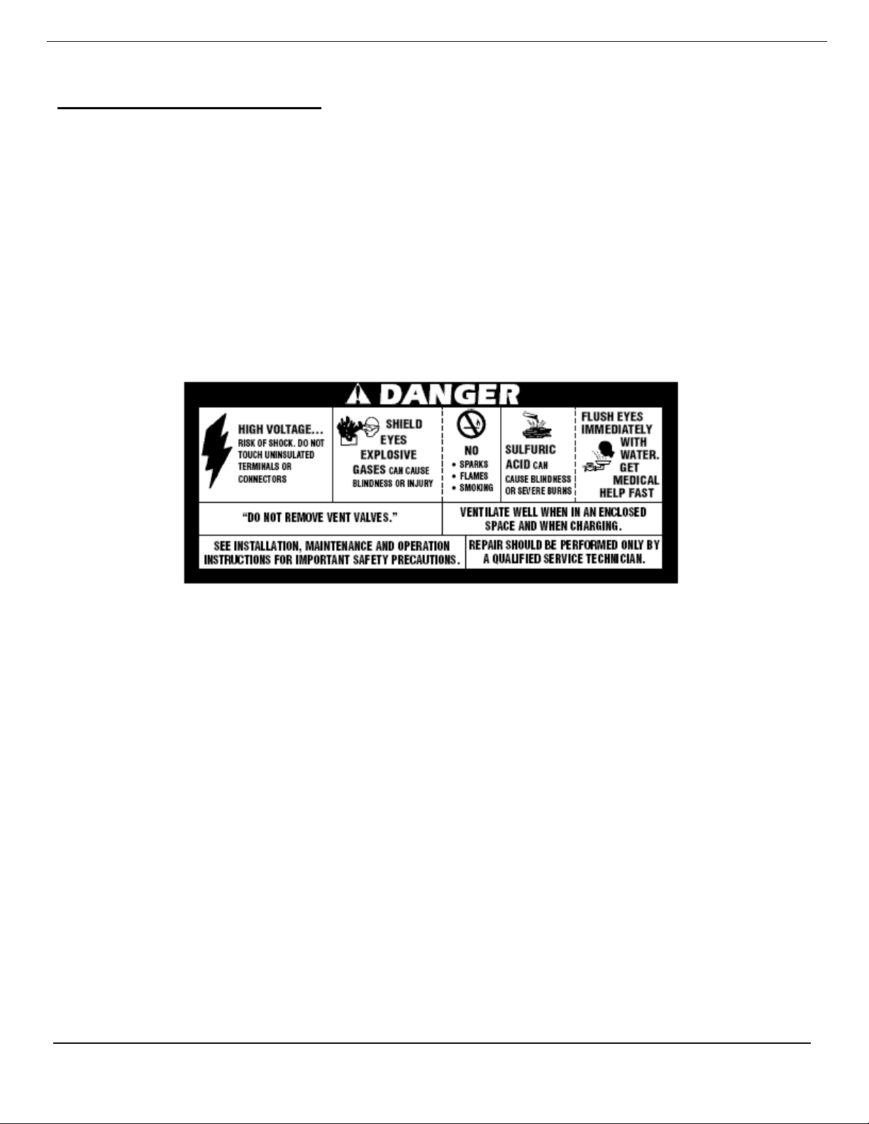
As a notice to all technicians and personnel in the near proximity of the batteries, a BCI warning label is in
plain view to indicate the potential hazards of battery systems.
Figure 3-1 BCI warni n g l ab el
3.1 Recommended Tools
The below lists are general recommendation and is not intended as a complete and specific list. Each
installation ma y req uire special t ools that cannot be identified without knowing the specific applic ations.
Review the a ppro pri ate ind ust ry rec omme ndat ion s, stat e and lo ca l codes f or the spe cif ic inf orma tio n.
3.2 Pers onn el Pr ot ect io n E q uip ment ( Saf et y )
• Use standard battery safet y pr a ct ic es
• Rubber or neoprene – acid resistant gloves
• Protect ive apr on
• Face shield/safety glasses or ANSI approved goggles
• Rubber sol ed saf ety sho es/ boot s
• Portable or permanent eye wash station
RS02044/1114/CD 7 www.cdtechno.com
Page 8

NOTE:
3.3 Installation Tools and Supplies
• Lifting sling or app ropr iat el y size d platform – f or lifting cells and modules.
• Insulated steel to ed s afe t y s hoes & r em o ve a l l met al s, i. e. r ings , et c – to ensure no short circuits.
• Sodium bicarbonate, 1 lb per ga llo n of wate r – to neutralize and clean up any electrolyte.
• Insulated tools – to ensure no short circuits between connections.
• Insulate d t orq u e wr e nc h – to ensur e no s h ort c i rc u its bet we en c on nect i on s.
• Digital voltmeter with three-digits and 0.25% accuracy minimum – to record init ial cell open circuit
voltages & ens ur e co rr ect a ss emb l y.
• Digital Micro-Ohm meter (DL RO) -to measur e c onn ec t ion r es i st anc es.
• Optional, one of the following; resi s t ance, conductance or im pedance meter – to record in itial
ohmic measurements.
• Non-metal lic br us h or pa d f or c leaning connections – to ensur e cle a n con n ect io ns f or g oo d
integrity.
• NO-OX-ID grease and applicator brush – to ensure good con nect ion integr it y thro ughout ser vice
life.
Part 4 - Receiving
4.1 Inspection at Time of Delivery
Great care has been taken to pack the battery for shipment to ensure its safe arrival. As soon as you
receive the battery, check the packing m ate r ia l f or evi d en ce of dam ag e in t r ans it. I f the packing mater i al is
physical ly d amag e d or wet a ci d st a ins ar e pr ese nt , make a notat ion on t he d e li ver y r ec ei pt before you
accept the shipment/delivery.
Freight carrier s g ener al l y r equi r e t hat t he c ar rie rs ’ r ep re sen tative inspect
concealed damag e withi n 15 days fr om dat e of del iver y to det ermi ne res ponsi bili ty.
The resolut ion of su ch cl aim s may exte nd up to ni ne mont hs.
Verify the number of cart ons and skids against the bill of lading and verify their contents against the
packing l ists. K eep a cop y of the ver if ied l ists for your i nsta llat io n recor ds. It is impor t a nt t o conf ir m that
the accessory package is pr esent and the quantities are correct. If help is requir ed, c a ll C&D cus t ome r
service department to report any discrepancies.
4.2 Damage and S horta ge Sit uat ion s
C&D ships FOB Pharr, TX (zip code 78577) (title/ownership passes to the ship-to/end user at t h e P har r, T X
warehouse ) . If s h ipm ent s ar e d amaged or if cartons or skids are damaged or missing, a claim must be filed
with the carrier. Plac e an immediate order for replacement with C& D. Pay both the original invoice and the
replacement invoice using th e replacement cost as t he amount of freight damages or shortages involved as
part of your c la im . If i nd ivid ua l com po ne nt it em s ar e m is s ing , a sh ort ag e r e por t s hould b e filed wi th in
30-days fr om the dat e of rec ei ving a sh ipment with the C&D customer ser vic e depar tme nt. Ma il
(express m ai l r ecom mended), e-mail customersvc@cdtechno.com
VERIFIED component-packing list. This verified list should show both the name of the packer, as well as
the quantities of items checked off by the receiver.
, call 1-800-543-8630 or fax a copy of the
RS02044/1114/CD 8 www.cdtechno.com
Page 9

Part 5 – Storage Prior to Installation
5.1 Storage Conditions
Store batteries indoors in a cool, well ventilated, clean, dry location and place in service as soon as possible
after rec e ivi ng .
5.2 Stora g e Tem p era tur e and Dur ation
The recommended temperat ure for storage is 50°F (10°C) to 77°F (25°C). msEndur II cells may be
stored at t hese temperatur es f or a ppr ox ima te l y si x months; longer stor age is detrimenta l to the cell and
can void the warr an t y if t he y ar e n ot given a fres h en ing c har ge wit h in t hat time period. A convenient
measurement to check the condition of the cell d uri ng st or ag e i s t o me as ure t he O p en C ir cu it Vol tag e
(OCV). A fully charged ATP cell has an approximate OCV of 2.16 volts. If the ATP series cell OCV drops
more than 0.0 4 volt s from it s rec eive d volt age or to less th an 2.12 volts, a freshening charge is required. A
fully char g ed AT L P cell has an approximate OCV of 2.10 volts. If the ATLP cell OCV drops more than
0.04 volts from its received voltage or to les s than 2. 06 vo lts, a freshening charge is required. Be sure to
record dates and conditi ons ( volt age, curre nt and re cha rge ti mes) fo r all cha rges durin g stor age.
Avoid exposure of a partially discharged cell to temperatures less than 0°F (-18°C), as this may cause the
battery electrolyte to freeze. This can permanently damage the batt ery a nd can caus e pote nt ial ly hazar dous
leakage.
Allowabl e st orage temper at ur e r a nge of 20°F (-7°C) to 90°F (32°C) is acc ept ab le. Higher than normal
storage t em per at u re s (77°F [25°C] nominal) will accelerate internal self-discharge of a ce ll by a f act or of
two for each 18°F (10°C) over the recommended nominal 77°F ( 25°C) storage temperature. This, in turn,
will reduce the allowable time before initial and/or boost charging by a corr espo nding amou nt.
If a freshening char ge is required, it is very important that boost or fres hening charges (2.40 v/c for ATP and
2.34 v/c for ATL P for 12 to 16 hours) be given at the appropr iate time to avoid major remedial action or
loss of prod uct as not ed in Pa rt 7.
Part 6 - Installation
6.1 Locatin g Batt ery Sy stem
Install the batteries in a clean, cool, and dry location. Avoid areas with direct sunlight and heat sour ces,
including electrical equi pment vents or e xh aus t s. Th e r ec omm en d ed ba tt er y ro om t em per at ur e of 77 °F
(25°C) pr o vi des t he b est com b ina t ion of performance a nd lif e. Lo wer temperatures will reduce battery
performance, while higher temperatures will improve battery per form ance but re duc e batter y servi ce life.
Avoid so urc es of hot or co l d a ir t ha t c o uld ca use t emp er at ur e var i at ions of ±5 °F (3° C ) with i n t he b att er y
assembl y. Such vari ation s will c ompr omi se opt imum bat ter y perf orm ance su ch as t he float v ol tages of
individual cells.
For additional information on installing batteries in modular systems, refer t o t he Sectio n 6.5 for instal latio n
details.
RS02044/1114/CD 9 www.cdtechno.com
Page 10

6.2 Ventil at i on
Although the ATP and AT LP series of batteries are valve reg ulated, the y do prod uce minimal gas
emissions during normal operation. If exposed to abnormal high voltage charging, the cells may vent
potentially explosive hydrogen gas. Hydrogen gas when accum ul ated i n a conf ined ar ea that exc eeds f our
(4%) percent by volume in air is explosive. C&D recommends not allowing hydrogen gasses of greater
than two (2%) p erce nt by vo lume t o acc umulat e. C onta ct the local code enforcement officer to determine
what codes and lev els are applicable to y our battery room inst allation. Lead aci d batteries should never
be installed in a seal ed, non-ventilat ed cabi net or encl osur e.
VRLA batteries subjected to extreme overcharge voltages have the potential to release hydrogen gas at a
rate of 0. 0 002 69 cub i c fe et per m in ute - amper e of charg ing c urre nt at 77 °F (25°C). The msEndur II
series test ing shows that th ey recom bi ne at near ly 99% eff ic ien cy und er norm al conditions. However,
compliance with codes and appropriate safety measures regarding hydrogen evolution is essential for the
safety of the equipment and personnel.
6.3 Floor Loading and Anchoring
Floor loading and anchor ing requirements are the responsibility of the user/installer and all applicable
building codes and regulations mus t be f ollowed. C&D provides connection drawings, weights,
dimensions, and floor loading infor m at io n o n our s yst em dr awi ng s f or r ef er enc e.
The msEndur II floor-mounting base has provisions for floor anchoring. Consult the applicable building codes
and regul at i ons f or sp ecific requir em ent s. I n al l c ase s, f lo or anc hor i ng is con s idered mandatory with floor
anchors to be installed in all locations provided unless otherwise spec if ied. Floor anchor sizing and
hardware are the responsibilit y of the us er/i nstal ler .
6.4 Spill Containment
Although th e ms E ndur I I ser ie s of b att er i es cont ai n no free flowing electrolyte, it is the sole responsibility of
the user/installer to follow all local bu ild ing and fir e cod es appl icab le to t he batte ry ins tal lat ion. It is
recommended consulting the local fire marshal or building inspector to determ i ne if s p ill cont a inment
is requir ed.
If requ ired, s p il l co nt ai nm ent c an b e pur cha se d f rom C &D. P lea se cont ac t your lo cal C& D r epr es en tat i ve
or C&D Custom er Ser vic e at 1-800-543-8630 or +1-215-619-2700 or emai l: cust omer svc @cdte chn o.com
RS02044/1114/CD 10 www.cdtechno.com
Page 11

Figure 6-1 Installation Usin g For kli ft
Figure 6-2 Installati on Usi n g Ho is t and Straps
Never attempt to move multiple m odules until module-to-module bolts have been
properly torqued to 60 ft-lb (81 N-m) using a torque wr enc h.
6.5 Module Installation
msEndur II battery systems are typica ll y shipped with the c ells pre-installed into the modu les f or ease of
transportation and instal latio n. In som e cases it may be neces sar y to have the ce lls ship ped separ atel y,
or to remove the cells from the modules prio r t o inst a llat ion .
It is esse nt i al and t h e r es p ons i bi lit y of t he cu stom er / inst a l ler t o be pr ope r l y tr a ined a nd h a ve s uit ab le
equipment to han dle thes e hea vy pro duct s. It i s the res pons ibi lit y of the cus tomer /i nsta ller t o provi de a
room properly designed f or a bat ter y syst em, inc lud ing appro priat e ven tila ti on, ai sle spa ce, egr es s, floo r
load capabilities and a level mounting surface.
6.5.1 Installation of M od ul es an d C ell s T oget he r
1) Floor anchoring is required for a safe installation. Mark the
location and install floor anchors, matching the anchor
holes in the fl oor -m ount ing bas e.
2) Install the floor-mounting base. Depending on the system
configuration and handling capabilities, the mounting
base may already be assembled with stacked modules.
See Figure 6-1
a) Floor mounting base alone: Lift t he m ounting base and
place it in the designated area over the floor anchors.
b) Floor mounting base assembled with stack modules:
Assemblies up t o f ou r ( 4) t ier s m ay be c aref u ll y
moved assembled with the use of a fork lif t , pallet
jack or other suitable lifting device; se e Fig ure 6-1.
c) A sse m bl ies c ons ist i ng of f lo or m ou nt ing b ase wit h
one stack module can be moved using the lifting strap
or a fork truck, pal let j ack or ot her ap pr op r iat e l ift i ng
device. See Fig ure 6. 2
d) Torque floor anchors per manufacturer’s
recommendations.
3) If the assembly requires additional modules, using appropriate
lifting equipment, place additional modules, one at a time, on
top of modules already in place. Proper ly alig n modul es
and mounting holes, and insert the bolts, washers and
nuts as shown in Fig ure 6-4. Module-to-module bolts
should be tor qued t o 60 ft -lb (81 N-m) using a torque
wrench.
6.5.2 Installation of M od ul es an d C ells S epa ra te ly
In cases where modules must be installed without cells, modules should be installed in the same manner
as deta il ed ( r em ov e “ shown”) in Sect io n 6. 5. 1. O nc e ba se and mo d ules h av e b ee n i nst a ll ed an d
properl y secur ed in pl ace, cells may be installed. For details on rem ov ing cells from modules, see
Section 6. 5. 3.
To install cells into empty modules:
RS02044/1114/CD 11 www.cdtechno.com
Page 12

NOTE: Handli ng of Indi vid ual Cel ls
cover seal ma y be com promi sed b y the modul e’s st eel e dge.
• When remove d, do not all ow cell s t o dr op. Ce ll s m ust b e l ai d d own i n a contr olle d
manner. A battery dropped may be damaged by the impact of falling even short
distance s. Some damag e may occ ur to int erna l com pone nts, not visi ble at i nst allat ion.
• Batteries should not be l aid , slid or dragged across pal l et s or r ough fl oo rs . Nails,
pebbles, floor imperfec tion s and ot her ob struc tio ns can dam age jar, cover or weld.
• If the lift tab le is not at proper ele vati on and cel ls are pu s hed i n at a n angl e, the j ar to
1. If not already done, remove cell front restraint bars and c ell side r est rain t plat es. Ref er to Section
6.5.3 for det aile d instructions on removal.
2. Prior to cell insertion assemble the two (2) side restraint plate bolts and washers (when required)
into the f lo at ing f la ng ed n ut s t hr ough the hex-shaped r ec es sed ho le s o n t he r ig ht s ide of th e
modules ( or both sides for t he 4 5”, 4 9” and 58” wide modules); Ref Figure 6-4A, Flange Nut
Detail). Do not comp let ely t ight en the bo lt/ wash er/n ut ass emb lies at this t ime.
3. T r an sf er c e ll s to be ins ta ll ed on to lif t t ab l e. Do n ot exc e ed m a xim um weig ht l im it of l if ting
equipment or l if t ta b le. In many cases, cells will need to be moved one at a time.
4. P os it i on lif t ta ble in f r ont of em pt y m o dul es, st art ing wit h t h e l o west em pty mo du le. T he t op of the
lift tab le s h oul d be e ve n wi t h t he b ott om s urf a ce of the module. C el l t erm i nal s shou l d f ace a way
from the module opening. Any metal surfac es tha t m a y com e i nt o co ntac t wi th th e t erm i na ls
should be insulated.
5. Af t er ch ecking the ce ll polarity/orientation against the system drawing/connect ion diagram, slide
cell from th e lif t t ab l e i nto t he em pt y mo dul e. Cell should slide directly into the module and should
not drop or n eed to b e l if te d in to p lac e. To prevent dam ag e t o t he ce l ls, do n ot att em pt to in st a ll
cells int o a m o du le t ha t i s ab o ve or be l ow t he su rf ac e of t he l if t t ab le. Slide th e c el l t o t he lef t wall
of the modu l e ( or to th e ce nt er par t it io n of t he 45 ”, 49 ” a n d 58” wi de mod u les ).
6. When the cell is fully inserted into the module, the jar/cover seal will protrude slight ly beyond the
front li p of th e m o dul e.
7. I nstall the remaining cells within the module repeating ste ps 2-5 until the module is full. After
each new cell is installed, insert metal cell spacer plate between each cell. The spacer plate
should be pushed to the back of the module. Slide the cell over to the pre vio usly i nsta lled ce ll .
This will ensure that the cells are all biased toward the side opposite of the cell side rest r ai nt
plate and side res tr a int har d war e. Th i s wi ll a llow ad eq uat e r oom for ease of i ns ert i on of the cell
side rest ra int p l ate . W hen installed properly, cell spacer plates should n ot re ac h t he j ar /c o ver
joint. If the cell spacer plate extends beyond the lower lip of the m odule, remove it, check for any
obstruct ions a nd re -install. See Figure 6-4
8. O nce all cells are installed within the module and spacer plates are in place, insert the cell side
restraint plate as shown in Figure 6-4. The cell sid e r est r ai nt p late s ho uld al s o be p ushe d t o t he
back of the module. W h en pr oper ly inst al led, th e ce ll side r estr aint plate sh oul d be full y seat ed
against t he ba ck of th e m odu l e a nd t he f r ont e dg e of t he p lat e sh o uld no t r ea ch t he jar cover se al.
With all cel ls, sp acer plates, and cell side restraint p lates instal le d wi t hin t he m o dul e, t h e front cell
restrai nt bar should be installed using all supplied hardwar e. The fr ont re str a int bar hardware
should not be com pl ete ly tig hte ned at th is tim e. S ee Figu re 6-4
9. Starting with th e t op m od u le, side restraint p lat e bo lts (installe d earl ier as descr ibed i n step 2)
should now be tightened. Bolts should be hand-tightened first to e ns ur e t hey are square ag ain st
the module and the cell side restrai nt plate. See Figure 6-4
10. The fo ll owi ng ste p s a re t o be f ol lo wed f or t h e co mp l et ion of th e as sem bl y of th e si d e r estr a int
plate bolts:
RS02044/1114/CD 12 www.cdtechno.com
Page 13

NOTE: Additional Module Assembly Guidelines
For system s us ing cam a s sem b li es i n pl ac e of side restraint plate bo lt s, r ef er t o
Appendix B
a) Align th e cell side restraint plate against the cell while keeping the plate straight and
parallel to the module side wall. Adjust bolts so they are both protruding approximately the
same amou nt out f r om th e s i de of t he m od u le.
b) Turn each bolt one rotation at a time alternating between the two bolts, ensuring to keep
the cell s id e r est r ai nt plate straight and parallel to the module’s wal ls and the protruding
bolt length of the two bolts the same.
c) Monitor the bolt/wash er/ n ut ass em b lie s t o e nsur e t hat th e f la nge nut remains nest ed i n t h e
module side panel recess and the bolt perpendicular to the cell side restr aint plate.
d) Continue to t ig ht en th e b olt s un t il t he GAP between the o ut s ide of the cell s i de r estraint
plate and th e insi de of the m odul e is wit hin th e target range as listed in Table 2 in
Appendix C
e) If there is n o m easuring device available the bolts should be tightened until t he inter-cell
connectors can be pr operly installed. Vertical connectors – connecting posts on cells on
tiers directly above/below each other – will be str a ight , pl um b a nd p ar a lle l t o a ll ot her
vertica l conn ector s. See F igur e 9-1.
11. The front cell restraint bar hardware should be completely tightened at this time. To maintain
seismic rating s, all front cell restraint bar hardware must be installed and torqued to 6 Ft-Lb (8 Nm). See Fig ur e 6 -4
• Foll ow th e spacing guidelines det ailed in Table 2 in Appendix C and not ed
above
• It is not a requir eme nt that the cell cover s touc h
• It is not a requir eme nt that the cell cover s pacin g is exa ctl y the sam e
• It is not a requir eme nt that the sid e restr ain t plat e bolt s bott om out
• Torque not to e xceed 15 Ft -Lbs for t he si d e r est r ai nt bol t/washer/nut
assemblies
RS02044/1114/CD 13 www.cdtechno.com
Page 14

CELL SPACER PLATE
msEndur II CELL
CELL SIDE
RESTRAINT PLATE
FRONT CELL RESTRAINT BAR
1
4
" BOLT
SIDE RESTRAINT
PLATE BOLT
SIDE RESTRAINT
PLATE WASHER
(WHERE APPLICABLE)
MODULE TO MODULE
BOLT, WASHER AND NUT
Figure 6-3 Base to Module Assembly
Figure 6-4 Spacer an d Front Cell Restraint Assembly
RS02044/1114/CD 14 www.cdtechno.com
Page 15

Figure 6-4 A Flange Nut Detail
Figure 6-5 Module and Faceplate Assembly
RS02044/1114/CD 15 www.cdtechno.com
Page 16

Note: msEndur II cells should never be lifted by the terminals.
Do not use the cell pull er too l as a lift ing de vic e.
6.5.3 Cell Rem oval and St ack Di sas sembl y
If a requirement to disassemble a module stack arises, it i s r ec omm en ded t o r em ov e t he ce ll s bef ore
disassembly. Once the batter y str i ng has b een r em o ved f r om ser v ic e, t he te ch ni c ian m ust u se
properly insulated tools and all appropriate battery safety methods. If removing cells from a new
system in pr epar ati on for installation, skip to step 5.
1. R em ov e t he f ac e plat e f r om t he s ubj ec t mo du le.
2. Disconnect the system ground connection.
3. For each connector attached to the cell, loosen (but do not remove) the terminal bolts at either end.
4. While holding the connector in one hand, remove the terminal bolts completely. Remove the connector
and set aside. Repeat for other connectors.
5. After performing the electrical preparation described above, the steps to physically remove the cell or
cells can be performed as follows: Starti ng wit h t h e to p m o dul e, l oosen cell side restraint plate bolts
until cell side restraint plate is loose. Do not remove bo lt s c om pl etel y. For s ystem s wit h Cam
assembl ies, s ee Appe ndix B.
6. Remove front ce ll r estr ai n t bar bolts, shown in Fig ur e 6-4. Restr ai nt bar m ay be lef t atta ched t o
modules us i ng r et a in ing r ing s t o pr e vent it f rom b e ing m isp l aced . The cell side restraint plates
can now be removed. This will allow the cells t o be moved apart for ease of removing the cell
spacer plates and the cells. The cell spacer plates can now be remove d.
7. Attach the “cell puller tool”, part number RE03197. This tool, show n in Figure 6-6, is available from
your local C&D TECHNOLOGIES representative.
8. Prepare for cell removal by moving an insulated platform lift or equivalent lifting apparatus in proximity to
the bottom of t he st ac k module from which the cell is to be removed as shown in Figur e 6-8. Mak e
sure all expo sed met al on t he platf orm is ins ulat ed. Verif y the ca pac ity of t he lift ing app arat us is
suffici ent to s af ely lif t the ce l l. B ef ore rem o vi ng t he c e ll, note the orientation of the cell in the
module, i.e., positive terminal up or down.
9. Pull the cell straight out onto the platform, shown in Figures 6-7 and 6-8.
10. Store rem ov ed ce ll f or re-install atio n or dis pos al.
11. Repeat steps 6-10 for all cells within a module before removing a module from the stack
12. Disassemble the stack modules by removing module-to-module bolts.
13. For re-installation of modules and cells, refer to sections 6.5.1 and 6. 5.2
RS02044/1114/CD 16 www.cdtechno.com
Page 17

Figure 6-8 Cell Installation and Removal Using Lift Tabl e
Figure 6-6 Cell Remo v al To ol
Figure 6-7 Removing a C ell
RS02044/1114/CD 17 www.cdtechno.com
Page 18

NOTE:
horizontal top termination kit.
6.6 Electrical Connect ions
• Always use protective insu lating equipment, s uch as g loves, sho es, eye a nd face pr ot ecti on.
Wrenches an d othe r tools must be prope rl y insula ted.
• Observe local, state, and national electric codes at all times. Always work wit h the batt er y
ungroun ded. B att er y g rou n d c onn ect i ons, if requ ired, shoul d be m a de last .
• To avoid working with high voltages, break the battery down into convenient lower-voltage
modules, equal t o or le ss th a n 48-volts.
• Always maintain a firm grasp on tools and hardware when working on the batter y. Dropped
hardware can cause a short circu it, possib ly resulting in serious pers onal injur y and/ or dam age
to the equ ipm en t.
• Before wor king on the batter y, be sure to dis charge static electr icity that can build up on
tools or the tech nician by touch ing a gr ound ed surf ac e in the vic init y of the batt ery.
6.7 Termi nal Pl at es
For reasons of safety, it is r ec omm en de d t hat t erm i na l pl at es be i nst al led b ef or e c onn ec tor inst a ll at io n as
describ ed in sect io n 6.9. I nt er co nn ect c el ls wi th t h e t in -plated (standard) copper connectors and stainless
steel hex head bolts and washer s in accor d ance wit h the c onn ection diagram supplied with each battery
shipment.
Prior to inst al lat ion, lig htl y bru sh with a br ass brus h or Sc otc h brit e™ type pad the battery terminals and
terminal p lat e c o nta ct su rf ac es. T hen a ppl y a t hi n coat i ng of NO -OX-ID type grease. The ATP and ATLP
msEndur I I ser ie s of b att er y terminals are ma de of a c o pper a l lo y wit h a t hi n lea d c oat ing . T er m ina l
plates ar e m ade of c op per wi t h a t hi n l e ad or t in c o at ing . On ce c oat ed wit h pro t ect i ve NO -OX-ID type
grease, any “exposed”, “un-tinned” or “ un-leaded” are a s, no m att er if f r om t h e f act or y or d ue t o o ve r
brushing, will be protected from oxidation by t he grease thus not require reworking. Optional: preheat the
NO-OX-ID type grease and apply warm. After working with any lead component, wash your hands.
For appli ca tio n i n w hic h cab le s exi t t he pos t m o un te d t ermi n al pla te an d ar e r out ed
horizonta ll y acro ss the top of t he mo dule; C&D recom men ds the us e of the op tio nal
6.8 Number i ng C ell s
For ease of identification and for record keeping, all cells of a battery should be number ed. Plastic
peel-and-st ick numbers are furni she d in the acc esso r ies cart on. Comm on pr act ice is to start wi th “1” on
the cover of t he incoming ( +) positive ter minal of the batt ery and follo w the electri cal c ir cu it wi th
succeeding numbers on the cell covers.
6.9 Interconnection
Cell series connect ion is m ad e f rom t he negative post of one c e ll t o t h e positive post of th e ne xt cell. It is
essential that the ce ll loc ation a nd ori entat ion m atc h the in clud ed drawi ng. All con nect io ns must b e
made as indic ated on the drawing with no deviations. If no drawing is provided or it is lost, contact C&D
before m aki ng an y c onne ct i ons .
The cells ship with NO-OX-ID grease applied by the factory to the terminals, however it may be
necessary to rework prior to connecting the cells with the supplied inter-cell con nectors. Refer to App endix
A for additional instructions f or reapplying NO-OX-ID grease.
RS02044/1114/CD 18 www.cdtechno.com
Page 19

NOTE:
Over-t or quei ng c an d am age t h e post s eal a nd d e gr ade con n ect io n i nt egr it y.
IMPORTANT:
Never operate a battery with loose or corroded connections.
Prior to installation, lig htly b rush wit h a br ass bru sh or Scot ch Brite ™ type pad t he b att ery termina ls an d
any contact surf aces of the int er-unit connections. Then apply a thin coating of NO-OX-ID typ e gr eas e t o
both the b att er y t er m inal s an d c ont ac t surf a ce s of t he i nter-unit connectors prior to installation. The ATP
and ATLP msEndur II series of battery terminals are m a de of a copper a ll oy with a thin le ad coa t ing . T he
inter unit connectors (cables and bus bars) are made of copper and have a thin lead or tin coating. Once
coated wit h prote cti ve NO-OX-ID type grease, any “exposed”, “un-tinned” or “un -leaded” coated areas ,
no matter if from the factory or due to over brushing, will be protected from oxidation by the grease thus
not require reworking. Optional: preheat the NO-OX-ID type grease and apply warm.
After working with any lead component, wash your hands.
The top row of connectors is to be installed first, then the second down and so on, working from the top
down. When installing connectors, install t he top (upper most) bolt first. Complete connector installation
by torqueing all c onnections to 160 in-lb. [18 N-m], usi ng an insulated torque-wrench.
After torqueing all connections an d with the batt ery still o n open cir cuit ( n ot con n ect e d t o th e cha rging
source), take post-to-pos t r esi sta n ce m easur ements. Start at o ne end of the str ing and wor k to the
other end, recording micro-ohm resi st an ce of eac h int er -cell connection betw een cell s. Clean and retorque connections (see Appendix B) of similar size connectors which exceed ±10% percent of the average
resistance of battery connections or five micro-ohms, whichever is greater.
Record an d r et ai n t he r e sis ta n ce r ea din g s w ith the
initial cha rg e i nf orm ati on fo r f ut ur e r efe re n ce. See Appe nd ix E .
CAUTION:
It is the sol e responsibility of the user to check connecti ons.
When chec ki ng con n ecti on s, d isc on ne ct t h e bat t er y f rom t he l o ad a nd th e c harging equipm e nt
and follow all the precautionary measures outlined above and in th e gener al saf ety ref er ence s.
Some res ist a nce m ea sur em ent eq u ipm en t m ay c a us e a s p ark when th e pr ob es ar e app li e d to th e
cell posts. Use appropriate safety precautions when conducting this measurement.
After connecting all cells of the batter y, che ck the bat ter y voltag e us ing a cal ibr ated d igita l DC voltm et er
with at le a st t hre e digits and 0.25% a cc ur ac y m ini mum . Bat t er y v olt ag e s hou ld eq ua l
the open circuit voltage of an individual cell multiplied by the number of cells in the battery. Example: (24
cells) x (2.1 6 VP C) = 51.84 OCV. If the OCV doe s not eq ual the exp ected va lue, insp ect th e sequ ence of
positive (+) to negative (-) connections. Further investigation may require re-inspecting each cell voltage
to confirm an acceptable value.
6.10 Tap Connections
Tap connections may electrically unbalance the battery system and may void the warranty. If a center
tap is used, ea ch side must h ave it s own char g ing unit .
RS02044/1114/CD 19 www.cdtechno.com
Page 20

NOTE
cause damage to equip ment.
Part 7 – Initial Charging
General I nf orm ati o n an d P re caut i on s
To safely c har ge th e m sE nd ur I I bat t er ies a nd avoi d dam aging the batt er y a n d/ or c o nne ct ed equ ipm e nt,
observe the following:
• Use a const a nt vo lt age c h arg er with o nl y dir ec t cur r ent ( DC). AC rippl e cur r e nt f rom ch arger shall
not exce ed f ive ( 5%) per ce nt of t he 8 -hour (amper e -hour) rati ng of t he ba tt er y in amps.
• Be sure c har ger i s t ur ned of f bef or e m ak ing el ectr i c al c on nec t io ns bet wee n t he bat t er y an d
system.
• Connect via the appropriate size cable. Verif y proper polar it y wi t h a vo lt m ete r b ef or e m ak ing f ina l
charger c on nec t io ns and t urn i ng on t h e ch arg er.
• Be certa in t hat a l l co nne ct i o ns ar e t ig h t a nd s ec ur e d bef or e t ur ni ng on t he c har ger .
The recomm ended metho d of pro vid ing an init ial /fr esh ening charg e (sect io n 5.2 and s ect ion 7.1 & 7.2 ) is
to first det erm i ne t he maximum allowable voltage that may be applied by t he connected equipment.
Divide this by the number of cells in the battery to obtain maximum average volt age per cell allowed by
the equipm e nt. Adj u st th is n umb er t o a r ecom m en ded va lu e f ou nd in T a bl e 1 a n d con t in ue c ha rging at
this voltag e.
Charging cur re nt to the b att er y s ho ul d be l i mi te d t o 25 amperes per 100-Ampere Hour
battery rating at the 8-hour rate. Higher charging current can cause overheating that
subsequently increases the internal resistance of the battery, which requi r es
additiona l cur rent t o compe nsat e for th e i ncr eas ed int ern al resi st ance. This cycl e is
referre d t o as “thermal runaw a y”, whic h has th e pote ntial to destr oy the battery and
RS02044/1114/CD 20 www.cdtechno.com
Page 21

Time
7.1 Initial Charge
All cell s ar e sh ipp ed f u lly c har ge d f r om t he f a cto r y wit h n o ne ed f or a n in it i al f r eshe n ing or eq ual iza t i on
charge. The cells should be constant voltage charged at the average float voltages as noted in Tabl e 1
below. However, when in storage or transit for an extended period (especially at temperatures above
77°F/25°C) or when the number of cells is greater than 24 cells; it is recommended the battery system
be given an initial freshening charge (see Table 1) at installation.
Table 1 – Initial Charge at 77°F (25° C)
Average Strin g
Cell
Type
ATP 2.25 to 2.30 2.40 +/- 0.02 12 – 16
ATLP 2.17 to 2.22 2.34 +/- 0.02 12 – 16
Float Voltage
77°F (25°C)
VPC VPC Hours
Average Strin g
Freshening
Voltage
Freshening /
Equalization
Charging
Notes:
a. B attery float voltage should be set at Table 1 average cell voltage multiplied by the number of cells in the battery string.
Individual cell float voltages may vary by +0.10/-0.05 volts from the average in a singl e s t ri ng.
b. I nitial battery charge current on the constant voltage recharge should not exceed 25 amps per 100 amp-hour batter y rati ng.
c. Average string float voltage must be adjusted based on temperatures which are above or below 77°F (25°C) - se e s ec ti on 8. 3.
d. Charging time will vary due to temperature if cell temperature is below 60°F (16°C), double the charge time for initial or equalize charge.
e. F or hi gh v olta g e strings, s ee S ec t io n 7. 1. 1.
f. If a battery load test will be perf ormed within 90 days of installation, an initial freshening charge followed by a 72 hour float charge (per
IEEE 1188) is r eq ui r ed to ensure f u ll capacity.
7.1.1 Init i al Ch ar ge – UPS Applic ation s
UPS battery strings typically contain many more cells connected in a series string versus
Telecommunications lower voltage applications. A UPS application may consist of 240 cells (480 VDC)
in a seri es as c om par e d wit h 12 t o 2 4 c el ls ( 24 t o 4 8 VD C) f or t h e t yp ical T el ec om app li c at ion. It is
recommended in High Voltage UPS applications, the ATP and ATLP series of ms En d ur I I b att e r ies b e
given a freshening charge at installation (see Table 1). This initial charge will assure higher initial
performance and reduce the t ime period required for the battery to achieve proper voltage balance
between the individual units.
7.2 Initial Charge Records
At the comp l et io n of th e in it ia l ch arg e and af ter th e c e lls h av e be en on f lo at cha r ge f or ap pr o xima te ly on e
week, rec or d volt ag e s of th e i nd ivi du a l ce l ls, t he t ot al batt er y vo lt age a nd am b i ent t emp er ature. Reta in
this inf orm at i on i n yo ur f il es f or f ut ur e r ef er en ce. T hi s inf or ma t ion est a bl is hes a bas e lin e f or f ut ur e
reference. The information below must be recorded or refer to RS-1992 foun d i n Appendix E. Make a
photocopy of the form and use it whenever nec es sa r y to r ec or d r e ad ing s t ak en on th e bat t er y.
RS02044/1114/CD 21 www.cdtechno.com
Page 22

IMPORTANT:
warrant y, b e sure to mai nt ai n cl ea r, si gn ed , and d at ed c opie s.
NOTE:
Some hydrogen gas may be liberated at equalize voltage.
Battery id entif ic ati ons
1. Date of readings
2. Battery total float voltage
3. A mb ie nt op er at ing tem pe ra ture
4. Date and description of initial or last equalizing charge
5. G eneral observations from visual inspection
6. Individual cell voltages
7. Connection resistance measurement
8. *O ptional: On e of t he f oll owi ng f or ce ll o hm ic t est er s : Im pe d anc e, Co nduc t anc e or Res i st anc e
9. N am e of i ns pection techn ic ia n
If you observe any unusual readings or visual indications, consult your C&D Technologies representative
and send a copy of your l atest m aint enan ce repo rt to y our loc al C& D representative
or the technical services department at C&D.
*Cell ohmic readings may vary by ±20% of the C&D Technologies published values. This variation does
not necessarily indicat e a problem with the condition of the battery.
Initial charge records are essential for review by C&D Technologies’ sales/service
represe nta t i ves i n t he e ve nt of a problem. Sin ce re cord s can mat erial ly aff ect your
Part 8 – Battery Operation
8.1 Float Charging
Standby batteries are connected to control circuits, which must be energized at all times.
msEndur II bat t er ie s mus t b e con st ant v o ltag e charg ed as de scr ibed in sect ion 7. Con nect ed to a l oad in
paralle l wi t h a c on t inu ou sl y o per ating power s up pl y, t h es e b att er i es a ss ur e inst a nt an eou s s u ppor t of th e
load in the event of a power failure or brownout. In addition to operating the connected load, the power
supply keeps the standby battery fully charged. This parallel interconnection and operation is called float
service. Max im um b att er y l ife c a n be e xp ect ed in f ul l f loat s er vi ce, i n whic h t he f r equ en c y an d de pt h of
discharges are kept at a minimum. Deep and/ or frequent discharges can shorten service life, even with
proper battery maintenance.
8.2 Equalize or Freshening Charge
Under normal operating conditions, it is not necessary to equalize or refresh the AT P and ATLP series of
msEndur I I batteries when used within the criteria described in sections 5.2 and 7.
An equalizing charge should be performed if individual cell voltages fall 0.05 volts below the average
float volt age as s pec ified in Tab le 1. Pres enc e of a minim um vo ltag e does not imp ly a batt er y is
malfunctioning or that it will not provide the necessary power when called upon.
RS02044/1114/CD 22 www.cdtechno.com
Page 23

NOTE:
to as “therm al runaw ay”.
NOTE:
Consult your C&D Technologie s r epr es e nta tive for answers to specific question s.
Chargers should be current limited to 25 amperes per 100-Ampere Hour battery rating.
Higher char gin g curr ent coul d pot enti all y destr oy the b att ery by ove rhe ati ng that
subsequently causes mor e cur rent to flow creati ng a vici ous c ycle so meti mes ref err ed
Use the equali ze vol tage s etti ng show n in Tabl e 1 for a per iod not excee ding 16 hour s.
8.3 Temp erat ur e E ff ect s on Bat t eri e s
C&D recomm e nds t h at t he b att er y b e oper at ed a t 77 °F (2 5° C) ± 10° F ( 5. 5° C) . For am bi ent te mp er at ur es
outside th e recom men ded tem pera tur e rang e, the f loat vo ltag e must be adj u sted b y 2mV per °F or
3.6mV per °C. Adjust as ind icat ed below.
Add 2mV (0.00 2 volt s) per °F or 3.6m V per °C be low 7 7°F (25 °C).
Subtract 2mV (0.002 volt s) per °F or 3.6mV per °C above 77°F (25°C).
If the bat ter y i s op er ated a t te mp er at ur es be lo w t he r ec om me nde d r a nge, t he c ap ac it y wi ll b e r ed uc ed
even with tem pera tur e comp ens ated c harg ing, which must b e compe nsate d for dur ing init ial s ystem
sizing.
RS02044/1114/CD 23 www.cdtechno.com
Page 24

CAUTION:
Only use a solut ion of w ater an d sodi um bicar bon ate, 1 gal lo n to 1 lb.
Part 9 – Maintenance
The msEndur II is a VRLA cell which does not require water addition and no specific gravities or water
levels need to be checked throughout its life. However, it is recommended to properly follow the below
maintenance procedure, this will assure that the batteries are well maintained and ready for operation
when needed. A blank inspection report (RS-1992) is shown in Appendix E.
9.1 Monthl y I ns pe cti on
1. Visual inspection of the battery for general appearance and connector conditions. Check for
bulging jars, corrosion build up or any signs of heat dam age to t he jars /co vers an d con nect ors.
Visually check cell spacing and cell side restraint plat e GAP as noted in Appendix C, Table 2.
2. Measure and record the total system float voltage.
3. Measure and record the total system float current.
9.2 Quarterly (including the above)
4. O ptional; measure and record one of the following: conductance, impedance, resistance or
interna l r esi st an c e of eac h bat t er y. C hanges over tim e of les s t ha n ± 20 % ar e ac ce pt ab le,
changes of g rea ter than 50% r equire further attention (such as a load test).
5. Me as u re and re c ord th e t em per at ur e of the n egat i ve t erm i na l o n ea c h ce ll .
9.3 Semi-Annually (including the above)
6. Measure and record the individual cell voltages.
9.4 Annually (includi ng t he a bo ve )
7. Re-torque cell connector bolts to 125in-lbs (14 N-m).
8. Any disassembled connections should be r e-t orqued to 160 in-lb (18 N-m).
9. Measure and record connector resistance r eading. If a value exceeds the average by 10% for
similar c on n ect io ns, s ee Appendix B and reference IE EE 1 1 88 f or mor e inf or ma t ion.
10. If possib le, m eas ur e a nd r ecord the tota l an d i nd ivi du a l A C r ip p le c urr en t or vo lt age.
11. Clean prod ucts wi th a sol utio n of 1 lb of sodium bic ar bo nate to 1 gallo n of water , if ne ce ss ar y.
Never use sol ve nt s t o c le an a bat t er y syst e m.
For more i nf orm at io n, IE EE 1 1 88 d is cus se s t he s ig nif ic a nce of co nn ect ion integ r it y, f urt her mai n te nan c e
techniques and testing information.
RS02044/1114/CD 24 www.cdtechno.com
Page 25

PROPER CELL SPACING
AND CONNECTORS
STRAIGHT
AND VERTICAL
IMPROPER CELL
COVER SPACING
AND CONNECTORS
ANGLED
SIDE RESTRAINT
PLATE
PROPER
LOCATION
SIDE RESTRAINT
PLATE
IMPROPERLY
ON JAR/COVER
JOINT
EXAMPLES OF
MODULE ASSEMBLY
ISSUES
CELL
COVER
SPACING
GAP
"Cell side
towards back
9.5 Module Asse mbl y A dj ust m ent s
A module assem bl y that ha s been i ncorr ect ly ass emb led in th e fie ld shoul d be adj uste d to ens ure
all cells, cell side restraint plates, cell spacer plates, connectors and hardware are properly aligned
and installed.
Common assem bl y issue s ( see F igur e 9-1):
1. C onne ct ors not p lumb an d vert ica l (due to larg e cell cover spacing) and th e GAP is not
within specifications noted in Tab le 2 in Ap pen dix C
2. Side restraint bolts not straight
3. Cell s ide restraint plate s and/ or cell spacer plates extending beyond the lower lip of the
module
4. Cell s id e r estr a i nt plates contacting the jar/ c o ver seal of t he c e ll (too far f or wa rd )
restraint plate
improperly
seated; needs
to be pushed
Figur e 9-1 Module Assembly Issues
RS02044/1114/CD 25 www.cdtechno.com
Page 26

If the sid e r est r ai nt p late or t h e c e ll cover spaci ng in a m o du le nee ds to b e adj us t ed f ol lo w t he s t eps
below. The technician m ust use pr oper ly i nsula ted t ools a nd all a pprop ri ate batt er y safet y met hods .
For improper cell side restraint plate positioning:
• Loosen – do not remove - the s id e r estr a i nt bolt s t o a ll o w th e cell side restraint plate to be
moved to t he pr op er loca t io n
• Push the cell side rest r ain t p late to the ba ck of the module and away from the jar/cover
seal joint
• Hand tighten the side restraint plate hardware while ensuring the bolts are perpendicular
to the cell sid e r est ra int pl at e. Th is can b e ac com p l ish ed by t ur ni ng t he bo lt wh il e
simultaneously pulling the bolt towards the outside of the module.
• Complete the assembly as noted in 6.5.2 notes 10 and 11
• Check the torque on all the terminal bolts as noted in section 6.9
For excessive cell spacing result ing in GAP values not to specification:
• The cell cover spacing can be reduced by tightening the side restraint hardwar e t o m o ve
the cell side r es t ra int p lat es . Star t at t h e t op t ier m odu l e f ol lo wing t he st ep s no te d in
section 6. 5.2.
• Refer to Table 2 in Appendix C for a guide on allowable GAP between the inside of the
module an d t he out si d e of t he cell sid e r est raint plate.
• After sett i ng t he GAP on all tiers as required, check the torque on all the terminal bolts as
noted in sect ion 6. 9
9.6 Performance Tests
If desired by the customer, a full-load performance test can be conducted at t h e us er ’s or ig i nal
specified discharge ra te or t h e a ppr opr i at e r at e b as ed o n con n ect or s izing p er t h e f ol lo wing
procedure:
• Equalize c harg e the ba tter ies if nece ssar y, ref er to se ct ion 8.2 eq ua lizat ion n otes.
• Let batt er ies f l oat charge for 72-hours.
• Perform the annual inspection.
• Run a discharg e test at the syst em des igned rate per IEE E 1188.
9.6a UPS Transf er Test s
A monthl y tr an sf er t est f or U PS s yst em s sho u ld n ot e xc eed 3 0 sec o nds of t he b att er y di sc har ge t im e at
the user’s originally specif ied discharge rate to verify system load transfer an d el ectr i c al s yst em
performa nc e. T he t i me t hat is r eq ui re d t o s ync hr on iz e t he UP S an d r et ur n t o r ect if i er p ower mu st be
taken into ac cou nt when c alcu lat ing tot al dis cha rge tim e.
(Deleted duplicate paragraph)
RS02044/1114/CD 26 www.cdtechno.com
Page 27

CAUTION:
at freshening/equalize voltage is impractical, pr om ptly recharge at fl o at vol ta g e.
Part 10 – Battery Degrad ati on
10.1 General Information and Precautions
When prop er ly m a int a ine d a nd c har ged , t he AT P and ATLP series of ms E ndur I I bat ter i es sh ould
provide many years of trouble-free service. However, despite their inherent dependability, failure to
operate a n d ma int a in t he m corr ect ly can le ad to dam age, short ened servic e l ife and po ssi ble los s of
service. The followi ng se ct i ons a ddr es s some of the m ost f r eq ue nt ly e nc oun tered errors.
10.2 Floa t V er sus Cy cle L ife
Standby batteries such as the msEndur II are designed and construct ed to provide long life in continuous
float ser vi c e. T he y d if f er in t he i r d es ig n f rom c ycl ing b att eries, such a s eng in e st ar t ing , so lar or tr act i on
types. Sta ndby bat ter ies are cont in uous ly char ged at a compar ati vel y low flo at vol tag e in par alle l wi t h th e
load, ready to supply instantaneous DC power either directly to the load or by way of interfacing
electron ic s, suc h as an u n int er r upt ib le po wer sup p ly ( U PS) sys t em. T he nam e “ st at i onary” implie s t he
battery is usual ly perm ane ntl y place d in a give n loc at i on a n d not t ra nsf err e d f rom p la ce t o p lac e in it s
service lif e.
As such, standby batt ery lif e is dir ect ly aff ect ed by and wil l be deg rad ed if subjec te d to repe at cyc ling .
Depth of discharge, num ber of discharges, rate of discharge, and the interval between discharges are all
determin i ng f act or s in bat t er y lif e. C yc li ng s h ou ld t her ef or e b e k ept t o a m i n imum .
To ensure that the bat ter y will per form dur ing powe r out age s and oth er emer gen cies, it is str ong ly
recommen ded th at t es t ing b e k e pt t o a m inim um in accord anc e with the f o llo wing practices :
• The performance of an initial acceptance test not to exceed user’s originally specified system
• reserve t ime.
• A full-load ser v ic e t e st sh o ul d be p erf orm e d no t m or e t ha n once e ver y 12 m ont hs t o ve r if y b att er y
capacity at u se r ’s or ig i na ll y s pe c if ied dis c harge rate.
• A monthl y tr an sf er t est n ot to e xc eed 3 0 sec o nd s of b att e r y dis c harge time at us er ’s or ig i nal ly
specified discharge rate to verify system load transfer and electrical system performance.
• The time t h at is r eq u ir ed t o s yn c hro n ize t h e U PS an d r et ur n to re ct if ier po we r m ust b e t ak en int o
account when calculating total discharge.
The user is expected to maintain complete records of all battery testing and emergency discharges in
order to comp ly wit h the req ui remen ts of the warr ant y.
RECHARGE BATTERIES AS SOON AS POSSIBLE AFTER AN EMERGENCY DISCHARGE.
Failure to re cha rge batt eri es immediate ly afte r emer gen cy disc harg e may le ad to sulf atio n,
or in the case of deep discharge, a complete battery failure due to hydration. If recharging
10.3 High Tem per ature O perat ion
Operating a battery at temperatures exceeding 77°F (25°C) will reduce the battery life.
Elevated temperatures accelerate the electrochemical reaction with i n t he lea d a c id b att er y.
For additional informatio n, ref er b ack t o Se ct i on 8 .3.
RS02044/1114/CD 27 www.cdtechno.com
Page 28

10.4 Low Float Volt age and Su lfa tion
Either because of incorrect charger voltage adjustment, excessive intermittent or static loads paralleling
the charging source, low oper ating temperature or simply not fully recharged; a battery may not receive
adequate charging voltage. In some cases, the charger may eve n be tur ned off , erro neo usly or by
choice. The n et res ult i s a batter y lef t in a part iall y dis char ged or under charg ed condit io n. The first
observable signs may be errat ic cell voltag es. Althoug h not vis ible t o t he ob ser ve r, t he p lat es wi ll
become sulf ate d.
If you suspect sulfated plates, contact the C&D Technical Services Department 1-800-543-8630 or 215619-2700 for assistance. Sulfated batteries are not fully charged batteries thus have not completed the
electrochemical react ion of recharge. Accordingly, they will have reduced capability. If allowed to
remain in a partially charged condition for an extended period of time, sulfated batteries may suffer
irrevers ib le d amage, requir ing r ep la cem e nt.
10.5 Hydration
A battery that has been severely over-discharged and left in a discharged condition without
immediate recharge is subject to damage known as hydration. This is a phenomenon in which the
electrolyte specific gravit y has been re duced t o a valu e so low it pe rm its the l ead com po nent s to
dissolve into the electrolyte.
The reaction of dissolut ion forms many compounds and salts, generically referred to as hydrate.
On recharge these compounds react to c log separ at or por es and f orm meta lli c lead. As tim e pas ses
thousan ds of shor t cir cuit p aths ar e cre ated i n the sep arat ors pl ace d betwe en th e positive and negative
plates to provide electrical insulation. Very often, the effec t of th ese s h ort c ir cu it s go es u nnot i ced except
for a slig ht increase in charging current. As the reaction continues, however, short circuits become so
extensive it is almost impossible to keep the cells charg ed. Finally, the cells experience total failure.
msEndur II batteries are more resistant to hydrat ion than t ypical wet cells, l arg ely becaus e of the th ick
absorbent g lass mat separ ator bet ween the p late s. Ho wever, in se vere ca ses of hydr atio n, int erna l
short cir cu it s c a n f orm.
10.6 Open Ci rc uit – Late Ins tal l at io n s
As soon as a batte ry is disconnected from a charger, local action (discharge) begins. This is caused by
inherent internal losses within the cell. In the case of msEndur II cells, a self-discharge is expected to
occur at a rat e of “u p to 3 .0 per c ent ” of fu ll ch arg e p er m on th at 7 7° F ( 25° C). T her ef or e, if ce ll s r em a in,
for whate ver r ea so n, on op e n ci rc u it ( wit h no cha r ge su pp l ied) f or pr o l ong e d per i o ds of t im e, t he af f ect ed
cells ma y be c ome su lf ate d and require corr ec t ive a ct i on in t h e f orm of a f re sh en ing ch arg e, s ee Sect i o ns
5.2, 7.1 & 7.2.
10.7 Parallel Battery Strings
When stri ng s of bat t er ies of equal voltag e a re co nn ect e d in p ar al lel , t he o ver al l ca pa c it y is eq ual t o t he
sum of the capacities of the individual strings. When paralleling valve-regulated batteries is necessary,
the extern al circ uit r es istan ce shou ld be mat ched for ea ch batt er y. A wide va ria tio n in batt ery cir cui t
resistance can result in unbalanced discharge (i.e., excessive discharge currents in some batteries and
less disch arge i n othe rs). A s a cons equen ce, cell f ail ures i n one batt er y stri ng and th e subseq uen t los s
of perform ance ca pac itie s of that str ing will resu lt in hig he r loads i n the l ower resis tanc e int ercon nect ions
of some para lle l string s tha t may e xcee d the rat ings of the batt er y inter con nect ions a nd/ or c ab les . C&D
recommends paralleling strings to obtain hig her capacity, to increase system reliability and with proper ly
install ed disc onn ects, perf orm m ainte nan ce on on e stri ng at a tim e.
RS02044/1114/CD 28 www.cdtechno.com
Page 29

NOTE:
any lead com ponent, w ash your hands.
Appendix A - Connections
A.1 Terminal Connections
1. Remove any remaining factor y -applied gr eas e co at i ng f r om t he te rm in als with a
dry cloth.
2. Lightly brush the terminal, cable lug and terminal plates contact surfaces with the supplied
brass bri st l e br us h o r s co tc h brite type pa d.
3. Coat al l elect r ical surf ac es with NO -OX-ID. (Optional: Use heat g u n or hot p late to m elt an d then
apply the NO-OX-ID greas e, no o pe n f lam es) .
4. (Optional) - Re-flow exc es s NO-OX-ID with heat gun and wipe excess.
5. I nst all h ardwa re an d torqu e to 160 i n. lb. (1 8 N-m).
6. Wash hands after wo rk ing wit h le ad.
A.2 Rewo rk ing Termi na l Co nnec ti ons
If a terminal connection needs to be reworked (for any reason) follow the below steps:
Once the batt ery str ing has bee n remo ved fr om serv ice us ing pr oper ly in su late d too ls and al l
appropr iat e b att e r y saf et y me th o ds r em o ve t he s usp ec t c o nnection(s).
1. Remove any existing grease using a dry cloth.
2. With a neutral izing solut ion c ons isting of one-pound sodium bicarbonate mixed with one
gallon of water, wipe the cover and terminal seal are a wit h a clot h moist ene d with the n eu tralizing
solution. Do not allow t he neutralizing solution to enter the cell. Rinse with clear water and dry
thoroughly.
3. L ig ht l y br us h t he t er m ina l, ca b le lug or t er m ina l pl at e c ont act s ur f aces wit h t he s up pl ied br as s
bristle br ush or Scotch brite™ type pad removing any oxidized or corroded areas.
4. Coat al l elect r ical surf ac es with NO -OX-I D. ( O ptional: Use heat g un or ho t plat e to me lt and th en
apply the NO-OX-ID greas e, no o pe n f lam es) .
5. (Optional) - Re-flow exc es s NO-OX-ID with heat gun and wipe excess.
6. Re-Insta ll hard war e and tor que t o 160 in. l b. (18 N -m) and measur e co nne ct i on r es ist a nc e.
If still > +10% consult C&D.
The ATP and ATLP msE ndur II seri es of bat ter ies termi nals, bus bar s, cabl e lug s
and termin al plat es are m ade of cop per an d have t hin layer of eit her ti n or lea d.
Once the t erm i nal co nn ect i o n i s co ate d w it h pr ot ect i ve NO-OX-ID type grease,
any “exposed”, “un-tinned” or “un-lea de d” ar ea s, n o mat t er if f r om th e f act or y
or due to over bru shing , wil l be prote cte d from o xidati on b y the grea se an d not
Optional: prehe at th e NO-OX-ID type gre ase a n d ap pl y w arm. Aft er w or kin g w ith
require r ew or ki ng.
RS02044/1114/CD 29 www.cdtechno.com
Page 30

Appendix B – Installation and Operation of Cam Assemblies
In some ca se s, t he side restr aint p lat e bolt s will no t be acc essi ble on ce th e b att er y st a ck h as be e n
install ed. For t hes e ins ta ll at io ns, C& D T ec hn ol og ie s of f ers c am a ss em bli es t hat m ount t o t he s id e of t he
module and pr ovid es a way t o tig hten an d loose n cell side restrai nt p lates f rom th e f ro nt of the m od u le.
To install cam assemblies:
1) Slide hex shaft through front lip of side flange & front channels See Figure B-1
2) Slide hex shaf t int o cam lob e and install retaining clip on each s ide of cam lobe Se e Figur e B-2
3) Locate position brackets over the cam assem bly and line up holes with threaded h o les in t he m od u le.
a) Refer to C am systems drawing M14043 for quantity of shims where required.
4) Bolt position brackets in place using (4) ¼-20 bolts. Torqu e to 60 in-lbs.
5) Rotate h ex s haf t 3/ 4 t urn so t h at t he f lat e dge of th e c am lo be bear s aga in s t the cell side restrain t
plate.
a) Cam assemblies installed on t he right – Countercl o ck wis e t o set / Clockwis e t o r e lea se
b) Cam assemblies installed on t he left – Clockwise t o se t / Cou nt er cl ock wis e t o r el eas e
Figure B-1 Cam Assembly Diagram
RS02044/1114/CD 30 www.cdtechno.com
Page 31

(Reference Figure C-1)
16
16.04"
AT(L)-07P
4
0.50 to 0.88
16
16.04"
AT(L)-15P,-17P
2
0.50 to 1.13
19
19.32"
AT(L)-07P
5
0.63 to 1.25
19
19.32"
AT(L)-09P
4
2.00 to 2.88
22
22.61"
AT(L)-07P
6
0.88 to 2.00
22
22.61"
AT(L)-11P,-13P
4
2.13 to 3.63
22
22.61"
AT(L)-15P,-17P
3
0.88 to 1.25
22
22.61"
AT(L)-23P, -25P
2
1.38 to 2.13
26
26.13"
AT(L)-19P, -21P
3
0.50 to 1.00
26
26.13"
AT(L)-27P, -29P
2
1.25 to 1.63
27
27.86"
AT(L)-09P
6
1.75 to 2.38
27
27.86"
AT(L)-11P,-13P
5
0.50 to 1.25
27
27.86"
AT(L)-15P,-17P
4
0.88 to 1.75
30
30.44"
AT(L)-07P
8
0.88 to 1.13
30
30.44"
AT(L)-23P, -25P
3
1.25 to 1.63
30
30.44"
AT(L)-35P, -39P
2
0.25 to 0.75
31
31.37"
AT(L)-11P,-13P
6
0.63 to 1.13
34
34.44"
AT(L)-09P
8
0.88 to 1.50
34
34.44"
AT(L)-15P,-17P
5
0.63 to 1.00
34
34.44"
AT(L)-19P, -21P
4
1.38 to 1.75
34
34.44"
AT(L)-27P, -29P
3
0.50 to 0.75
35
35.76"
AT(L)-07P
10
2.13 to 2.38
39
39.54"
AT(L)-23P, -25P
4
1.00 to 1.38
40
40.86"
AT(L)-13P
8
1.25 to 1.63
40
40.86"
AT(L)-15P,-17P
6
0.88 to 1.25
43
43.62"
AT(L)-07P
12
3.00 to 3.25
43
43.62"
AT(L)-35P, -39P
3
1.00 to 1.38
45 *
45.53"
AT(L)-27P, -29P
4
0.75 to 1.00
49 *
49.40"
AT(L)-19P, -21P
6
0.88 to 1.13
58 *
58.37"
AT(L)-23P, -25P
6
0.63 to 1.00
58 *
58.37"
AT(L)-35P, -39P
4
0.78 to 1.00
Figure B-2 Cam Assem bly Detail
Appendix C GAP and Module Assembly Details
Table 2 – GAP and Module Assembly Details
Module
Size
Module
Width
(Reference)
Cell Size
# of
Cells
Wide
Target GAP
Range
(inches)
RS02044/1114/CD 31 www.cdtechno.com
*These modules have cell side retention plates on both sides of the module
Page 32

SIDE RESTRAINT
PLATE
BOLTS
SPACING BETWEEN CELLS
REMOVED/ MINIMIZED
BY PROPER ASSEMBLY
OF SIDE RESTRAINT PLATE
GAP
INTER-CELL
CONNECTORS
VERTICAL WITH
PROPER INSTALLATION
OF SIDE RESTRAINT PLATE
Torque not to
exceed 15 Ft-Lbs
INTER-CELL CONNECT O RS
SPACING BETWEEL CELLS
CELL SID E
PLATE BOLTS
VERTICAL WITH PROPER
INSTALLATION OF CELL
SIDE RESTRAINT PL AT E
RS02044/1114/CD 32 www.cdtechno.com
Figure C-1 Module Assembly Details
RESTRAINT
REMOVED/MINIMIZED
BY PROPER ASSEMBLY
OF CELL SI DE RE ST AIN T
PLATE
Page 33

Appendix E – B att er y Ins pec t io n Re p ort
RS02044/1114/CD 33 www.cdtechno.com
Page 34

RS-1992
BATTERY CHARGE STATUS Open Circuit Float Equalize
BATTERY BUS VOLTAGE Vdc Vdc Vdc
LOCATION:
Cell #
Volts
+2.000
Serial #
Connection
Resistance
Internal Cell
Conductance/
Impedance/
Resistance
Cell #
Volts
+2.000
Serial #
Connection
Resistance
Internal Cell
Conductance/
Impedance/
Resistance
RS02044/1114/CD 34 www.cdtechno.com
Page 35

Appendix F – Recycling
Lead-acid batteries are recyc lable and C&D Technologies currently has a low cost, convenient, and
environm enta lly saf e collectio n a nd r ec yc l ing p rog r am. V is it t h e C& D We b s ite at www. cd t ec hno .c om f or
further inf orm ati on.
RS02044/1114/CD 35 www.cdtechno.com
Page 36

Figure & Tabl e Index
Figure 3-1 BCI warning label ................................................................................................................ 7
Figure 6-1 Installation Using Forklift .................................................................................................... 11
Figure 6-2 Installation Using Hoist and Straps ..................................................................................... 11
Figure 6-3 Base to Module Assembly .................................................................................................. 14
Figure 6-4 Spacer and Front C ell Res tra int As semb ly .......................................................................... 14
Figure 6-4A Flange Nut Detail ............................................................................................................ 15
Figure 6-5 Module and Faceplate Assembly ........................................................................................ 15
Figure 6-6 Cell Removal Tool ............................................................................................................. 17
Figure 6-7 Removing a Cell ................................................................................................................ 17
Table 1 – Initial Charge at 77°F (25°C) ............................................................................................... 21
Figure 9-1 Module Ass embly Issues ................................................................................................... 25
Figure B-1 Cam Assembly Di agram .................................................................................................... 30
Figure B-2 Cam Assembly Det ai l ........................................................................................................ 31
Table 2 – GAP and Module Assembly Details ..................................................................................... 31
Figure C-1 Module Assembly Details .................................................................................................. 32
RS02044/1114/CD 36 www.cdtechno.com
 Loading...