

Page 1
RETURN
RECYCLE
RS 1942
“L” SERIES NEBS COMPLIANT
STANDBY BATTERY RACKS
ASSEMBLY INSTRUCTIONS
General: These instructions detail the proper procedure for
installing C&D Technologies' Powercom Division (C&D) NEBS
compliant battery racks. The following describes how to
locate, assemble, and load open-frame racks for C&D
battery mounting applications. Proper attention to these
instructions will help ensure safe, trouble-free performance.
Rack Location: Locate racks in a clean, cool, dry place so
the batteries are not affected by sources of radiant heat,
such as sunlight, heating units, radiators, steam pipes, etc.
Variations of more than 5F (3C) between cells may
cause the battery to float and operate at different voltage
ranges. Top rows of batteries in multiple-tier configurations
tend to operate at slightly higher temperature than those
on lower tiers. Always provide adequate ceiling clearance
for ventilation and maintenance.
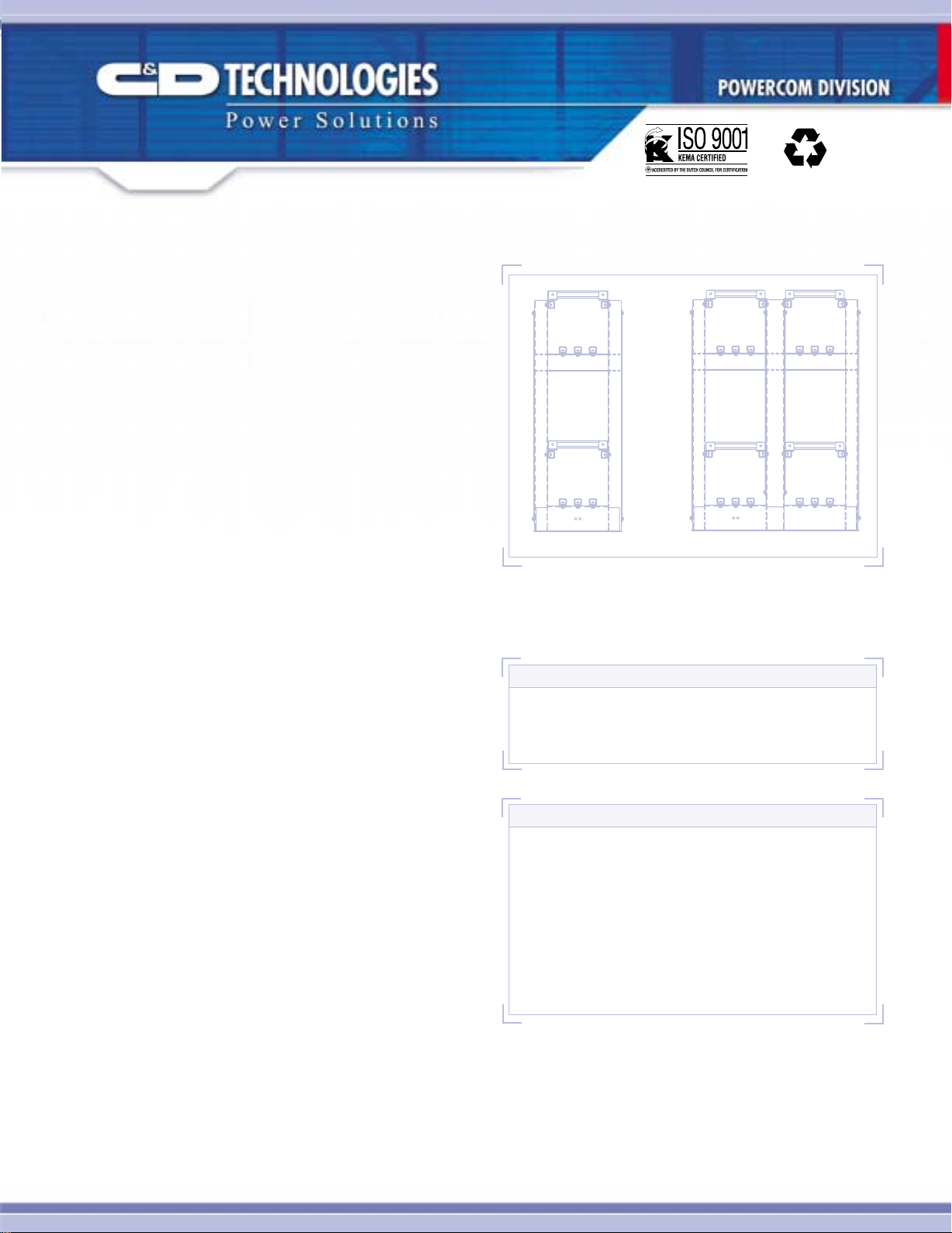
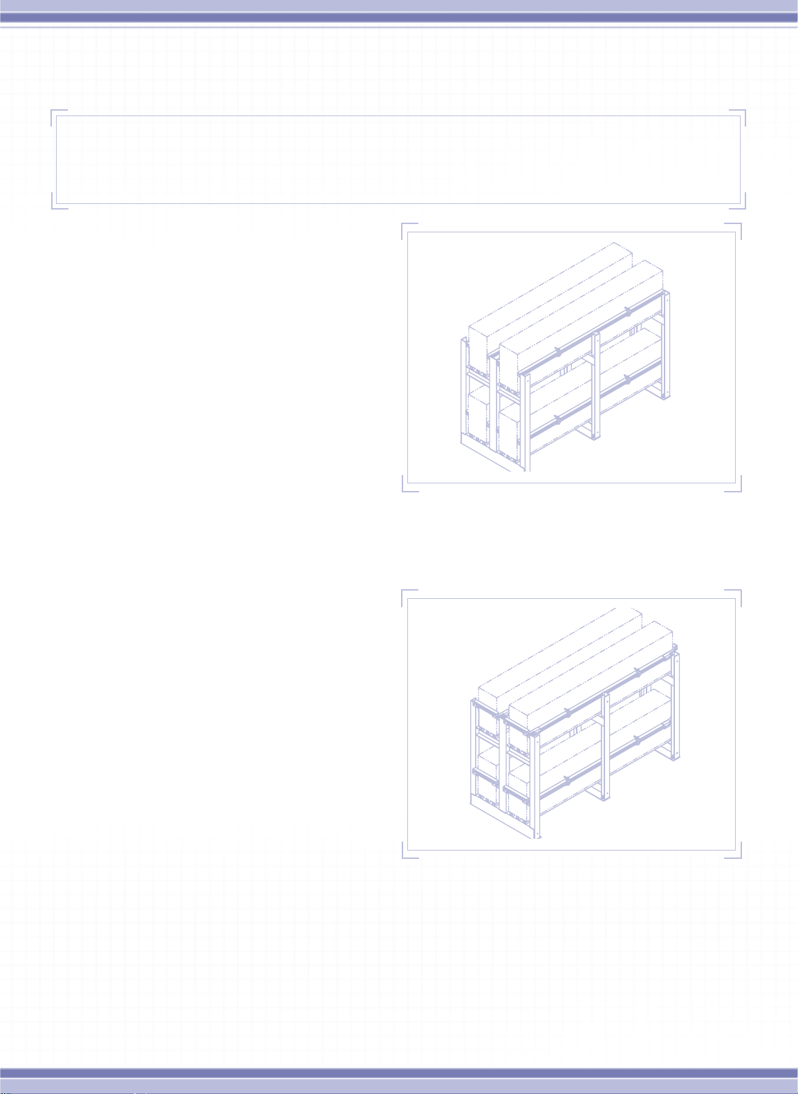
LEAD
FIGURE #1 End view of 2-tier and 2-tier/2-row racks.
Anchoring: To provide stability, safety , and seismic integrity,
racks must be securely anchored to the floor. Anchor bolts
are to be installed per vendor’s specifications and in
accordance with applicable codes. Do not attach rack to
walls without consulting C&D first. Mounting holes are
provided in the base of each frame. All frames must be
secured to floor using all anchor locations. It is the
responsibility of the customer to secure racks in
accordance with allowable floor loading, applicable
codes and regulations.
Grounding: Rack grounding provisions are integrated into
the base of each frame. Two 7/16” (11mm) diameter thru holes
are located at the center of the frame's bottom cross member
and may be used to secure a standard NEMA lug. These
two holes have 1.0” (2.54cm) between centers and have
been masked and are free of powder coating to allow for
electrical contact. Frame to frame grounding integrity is
accomplished via the lower support rail, attached to
each frame with an Internal/External “star” washer.
NOTE:
Floor mounting hardware is to be determined in
accordance with applicable building codes, not by
C&D. For proper certification, a floor anchor must
be a minimum or equivalent to an Hilti HSLM12-25.
CAUTION:
Do not install batteries until the rack has been properly
installed, with all bolts tightened to specified torque and
frames anchored to the floor.
Do not use oil, grease or any other lubricating agent as a
lubricant for cell installation. This could void the warranty.
Lubrication is usually not required due to the low friction
interface of the insulated covers. If necessary, a small
amount of water or unscented talcum powder can be
applied to the rail covers to reduce friction.
Page 2
RS 1942
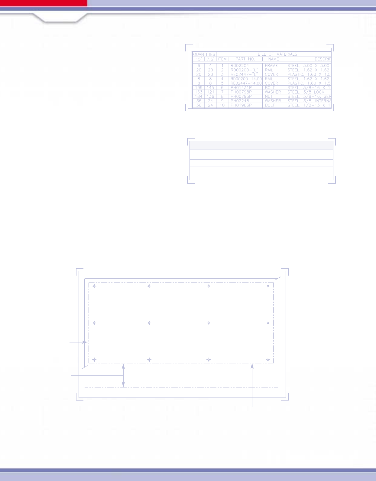
MATERIAL VERIFICATION
Battery racks are shipped unassembled with a complete
set of related drawings and documentation. Check received
parts and quantities against the rack’s Bill of Materials
(reference Table #1) on the provided drawing or packing list.
Do not assemble rack if parts are missing or quantities are
incomplete. Please contact C&D’s customer service,
800-543-8630 with any problems.
REQUIRED TOOLS
Torque wrench (0 to 120 ft.-lb.) with hex sockets for 3/8”
and 1/2” hardware. Adjustable wrench or 3/8” and 1/2” box
wrench, tape measure, square and leveling device.
Note: Consult manufacturers’ instructions for tools
required to install floor anchoring hardware.
INSTALLATION DETAILS
Bolted connection details are located at the end of
installation manual for reference. Torque values for
hardware are shown in Table #2.
LOCATION OF RACK
When determining the rack location and floor anchor pattern,
use applicable drawings provided with rack shipment.
Locate the racks’ general position, considering boundary
and aisle clearances. Locate floor anchoring locations
using provided drawings.
TABLE #1 Sample Bill of Material.
TORQUE VALUES
Hardware Type Torque Value
3/8”-16 Bolt, Nut and Lock Washer 15-20 Ft.-lbs (20-27 N•m)
1/2”-13 Bolt, Nut and Lock Washer 55-65 Ft.-lbs. (75-88 N•m)
3/8”-16 Bolt, Strut Nut and Lock Washer 19 Ft.-lbs. (25 N•m)
TABLE #2 Tourque Values.
Typical rack
clearance, 2 min.
Typical aisle
clearance, 36
FIGURE #2 Rack Assembly Location and Anchor Bolt Pattern.
External rack dimensions.
See assembly drawings.
Page 3
ASSEMBLY INSTRUCTIONS:
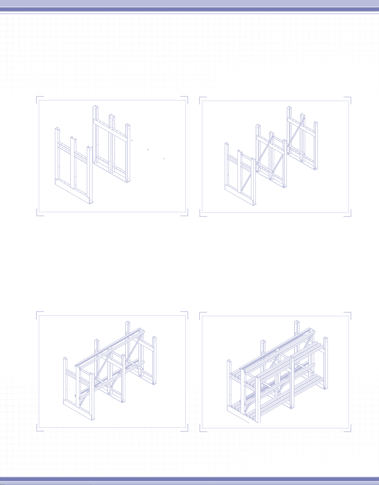
1 Initial Assembly: Place frames over installed floor mounting hardware, finger tighten. See Figure #3. (Floor anchors are
not supplied with rack) All frames must be in the proper orientation as shown on the rack assembly drawing. Install back
(away from aisle) cross braces for single row rack and center braces for double row rack. See Figure #4. Please refer to
rack drawing for proper orientation of cross braces. Refer to Detail #1 for brace to frame installation and Detail #3 for
brace to brace connections.
FIGURE #3 Placing Frames.
FIGURE #4 Installing Cross Braces.
Place support rail(s) in location using supplied 3/8” bolt, lock washer and serrated strut nut. Ensure that the strut nut has
properly engaged the strut.
Side Rails: Install back side restraint rail for 2-tier racks and center side rails on 2-tier/2-row racks.
2
See Figure #5. Refer to Detail #2.
3 Installing Support Rails: Install support rails from the back to front on 2-tier racks and from the center outward
on 2-tier/2-row racks. See Figure #6.
FIGURE #5 Installing Back or Center Side Restraint Rails and Covers.
FIGURE #6 Installing Support Rails and Covers.
Page 4
4 Leveling: With all support rails (not all side) rails and covers in place, the rack needs to be checked for level
and square. Shim frames as necessary to obtain level and squareness. Shims are not supplied by C&D.
With all frames level and square, torque cross brace bolts then torque the support rail to frame bolts.
T orque anchor bolts to manufacturer’s recommended value.
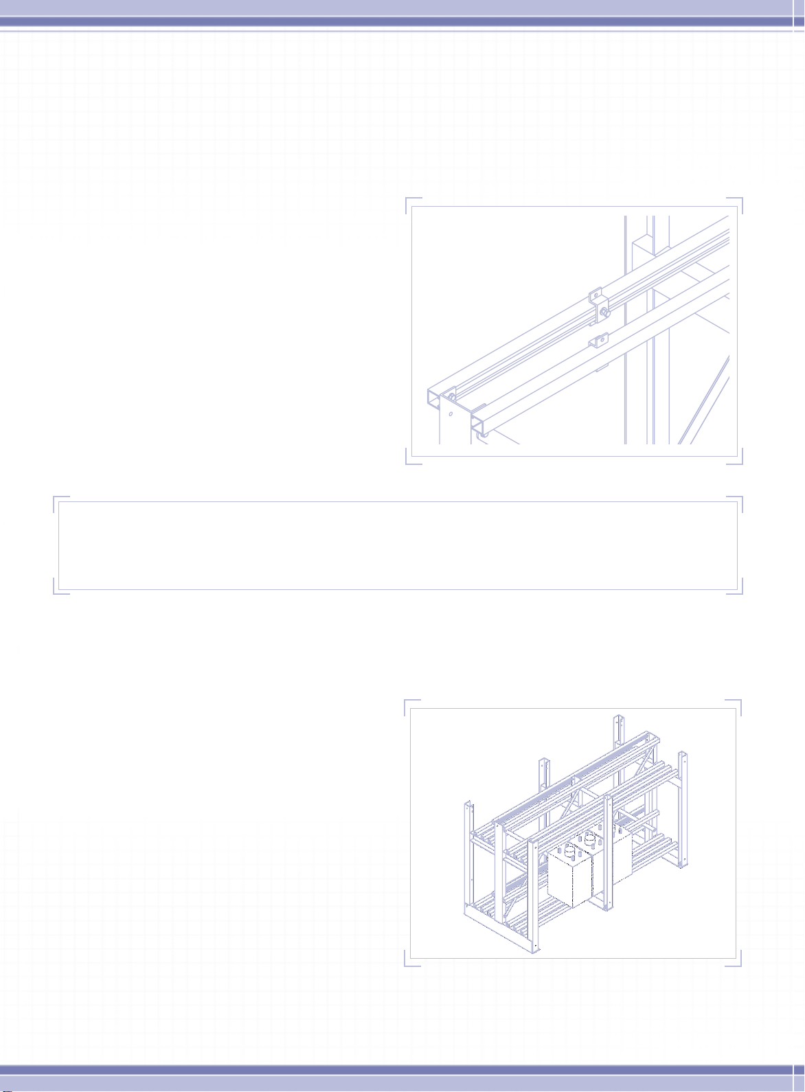
5 Install Inward Bracket of Battery Restraint Brackets:
Install partially assembled battery bracket in approximate
location with hardware loose, so bracket may slide into
exact location at a later step in the installation. This
bracket may not be required, depending on the rack
drawings. See Figure #7 and Detail #4.
FIGURE #7 Install Bracket Top Rail.
IMPORTANT STEP:
Place front restraint rail and cover on frame cross member (top and bottom rows) to be installed after all batteries
are in place. These rails should be slid up into position rather than dropped down from the top.
6 Cell Installation Procedure: If not instructed otherwise, install cells starting at the center of the bottom row
and working out to each end, install cell foam battery spacers as supplied if indicated by drawings.
7 Battery Restraint Bracket Assembly: Install the
tie rods and covers of the battery restraint bracket
assembly. See Detail #4. If batteries are completely
installed before this step, installing tie rods and
covers will be very difficult.
8 Cell Installation Procedure Continued: Do not use
oil, grease or any other lubricating agent, as a lubricant
for sliding batteries into place. Use a small amount
of water or unscented talcum powder to help reduce
friction on rail cover. Pay close attention to the
polarities and terminal placement. Refer to the
battery’s Installation and Operating Instructions
Manual for more details. All cells should be pushed
back against the back restraint rail and cover.
Repeat this procedure for all remaining rows and
tiers. Completely finish the bottom row before
starting the top row.
FIGURE #8 Bottom Cells Installed.
Page 5
SAFETY NOTE:
Take all necessary safety precautions when installing the top row of batteries and rack components,
as to not drop anything on the batteries below.
9 Front Restraint Rails: With the batteries in place,
slide the front side restraint rails and covers up into
place. See Figure #9. There should be a maximum
of 1/8” gap between side restraint rails and covers to
batteries. If there is interference between battery and
rail, confirm that the battery is pushed to the back
for single row and towards the center for double
row racks. If there is still interference, stop and
contact C&D immediately. If there is a gap greater
than 1/8” (3mm), contact C&D immediately.
10 Battery Restraint Bracket: Complete the installation
of battery restraint brackets, refer to Detail #4.
FIGURE #9 Install Front Side Restraint Rails and Covers.
11 Install End Restraint Rails and Bracket:
Install corner brackets, end rails and covers.
Position end restraint rail and cover against end
of battery. See Figure #10 and Detail #5.
FIGURE #10 Install End Restraint Brackets, Rails and Covers.
Page 6
RS 1942
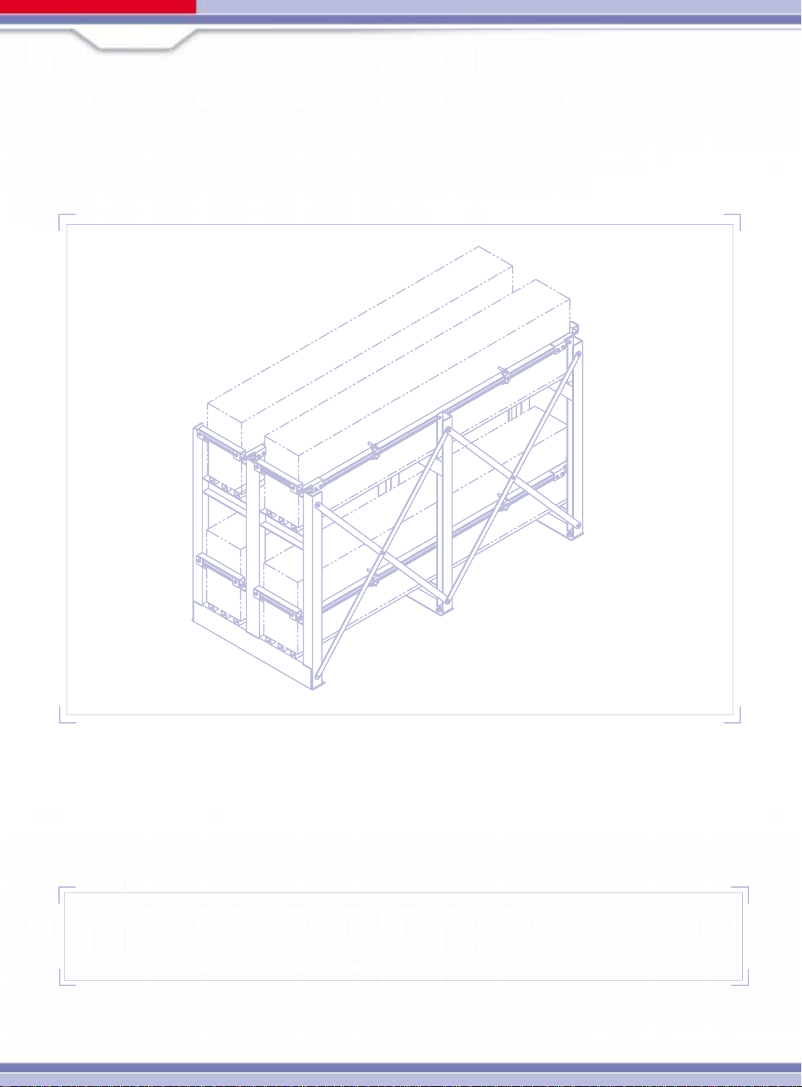
12 Install Front Cross Braces: Install front cross braces for single row rack and front & rear cross braces for double
row racks. Note that the center bolt must be inserted into the brace from the battery side. If installed incorrectly the
bolt may puncture the battery container during a seismic occurrence. See Figure #11 Details #1 and #3.
FIGURE #11 Completed Rack Assembly.
13 Batterty Arrangement: Install inter-cell and inter-unit connectors and cable assemblies as specified by the battery
arrangement. Refer to battery installation manual for more detail on battery connections.
ADDITIONAL INSTRUCTION FOR MULTI-RACK ARRANGEMENTS
Back to Back Assembly: Single row racks which are installed in an back to
back arrangement should be spaced a minimum of 2” apart.
Page 7
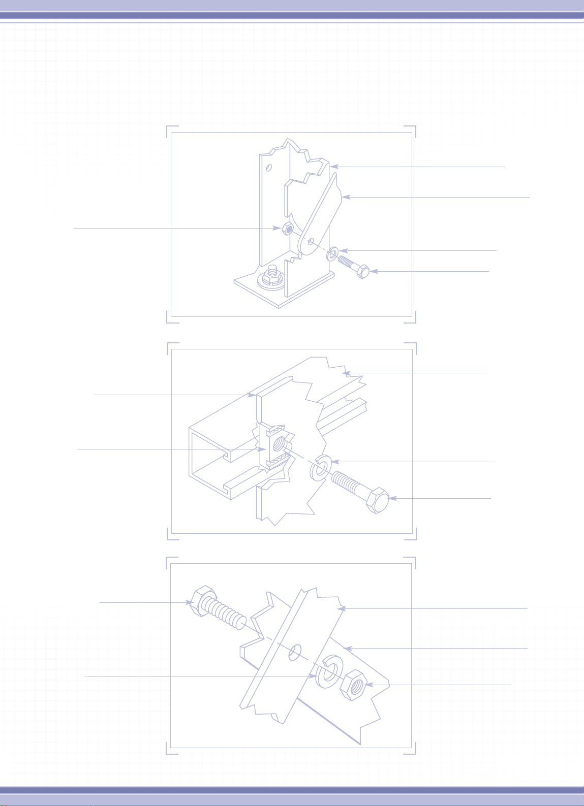
CONNECTION DETAILS FOR RACK ASSEMBLY.
Typical Bolted Connections: These typical details are to be used unless detailed specifically on drawing.
Use torque values from Table #2. For all values.
Nut, 1/2-13
DETAIL #1 Brace to Frame Connection.
Frame, Typical for
Both Side Restraint
and Bottom Rails
Frame Upright
Brace
Lock Washer, 1/2
Bolt, 1/2-13 x 1.50
Strut, For Support
Rails or Side Rails
Serrated Nut
Bolt, 3/8-16 x 1.00
Note: Bolt head must
be facing Battery
3/8 Lock washer
Lock Washer, 3/8
Bolt, 3/8-16 x 1.00
DETAIL #2 Rail to Frame Connection.
Brace
Brace
Nut, 3/8-16
DETAIL #3 Brace to Brace Connection.
Page 8

CONNECTION DETAILS FOR RACK ASSEMBLY.
Typical Bolted Connections Continued: These typical details are to be used unless detailed specifically on drawing.
Bracket
Tie Rod and Poly Tubing
Corner Bracket
3/8-16 x 1.00 Bolt
and 3/8 Lock Washer
Serrated Strut Nut
5/16-18 Nut and
5/16 Lock Washer
3/8-16 x 1.00 Bolt
and 3/8 lock washer
DETAIL #4 Battery Restraint Assembly Details.
End Restraint Rail
and Cover.
Serrated Strut Nut
1400 Union Meeting Road
P.O. Box 3053 • Blue Bell, PA 19422-0858
(215) 619-2700 • Fax (215) 619-7899 • (800) 543-8630
powercom@cdtechno.com
www.cdtechno.com
DETAIL #5 End Restraint Assembly Detail.
Any data, descriptions or specifications presented herein are subject to revision by C&D Technologies, Inc. without
notice. While such information is believed to be accurate as indicated herein, C&D Technologies, Inc. makes no
warranty and hereby disclaims all warranties, express or implied, with regard to the accuracy or completeness of such
information. Further, because the product(s) featured herein may be used under conditions beyond its control, C&D
Technologies, Inc. hereby disclaims all warranties, either express or implied, concerning the fitness or suitability of
such product(s) for any particular use or in any specific application or arising from any course of dealing or usage of
trade. The user is solely responsible for determining the suitability of the product(s) featured herein for user's
intended purpose and in user's specific application.
Copyright 2003 C&D TECHNOLOGIES, INC.
Printed in U.S.A. RS-1942 5M/1202/TD/1
 Loading...