

查询PT500-M1ABCHPHN供应商
Product Data Sheet
FEATURES
500 WATT
AC/DC POWER SUPPLY
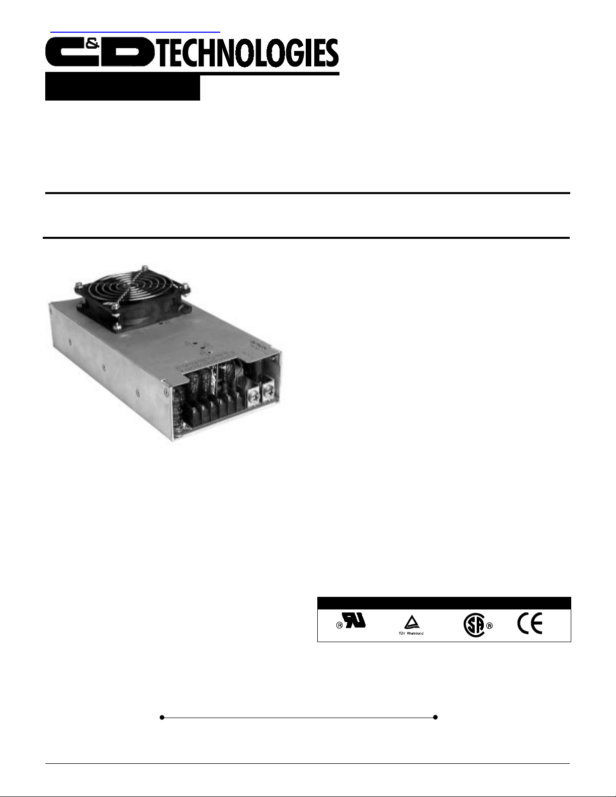
PT500
DESCRIPTION
The PT500 Series is a family of compact, fully featured,
multiple-output 500W power supplies with a 3.3V main output.
These high-current, 3.3V output platforms will support
requirements in which the logic has largely migrated from 5V
to 3.3V . With active Power Factor Correction (PFC) to EN610003-2, wide-range input of 90-264VAC, EMI compliance to FCC
and VDE Class B, and “CE” Marking, the PT500 Series is
ideal for systems targeting worldwide markets. The complement
of standard features includes remote sense compensation, output
voltage adjustment, remote inhibit, power fail warning, and
thermal shutdown. All outputs are fully isolated and regulated.
A complete array of output voltage configurations is available
to handle a broad range of applications. Available options
include a cover with integral fan and active current sharing for
redundant applications.
ll
l Active Power Factor Correction
ll
ll
l 3.3V Main Output
ll
ll
l High Surge Current Auxiliary Outputs
ll
ll
l Fully Isolated Outputs
ll
ll
l One, Two, Three or Four Output Models
ll
ll
l N + 1 Current Sharing
ll
ll
l FCC/VDE Class B EMI Filter Standard
ll
ll
l Fast Transient Response
ll
ll
l Optional Cover With Fan
ll
Internet: http://www.cdpo werelectronics.com
Power Electronics Division, United States
3400 E Britannia Drive, Tucson, Ariz ona 85706
Phone: 800.547.2537 Fax: 520.770.9369
PT500 4/99 REV A Page 1
132 Shannon Industrial Estate, Shannon, Co. Clare, Ireland
Tel: +353.61.474.133 Fax:+353.61.474.141
AGENCY APPRO V ALS
Power Electronics Division, Europe
C&D Technologies (P o w er Electronics) Ltd.
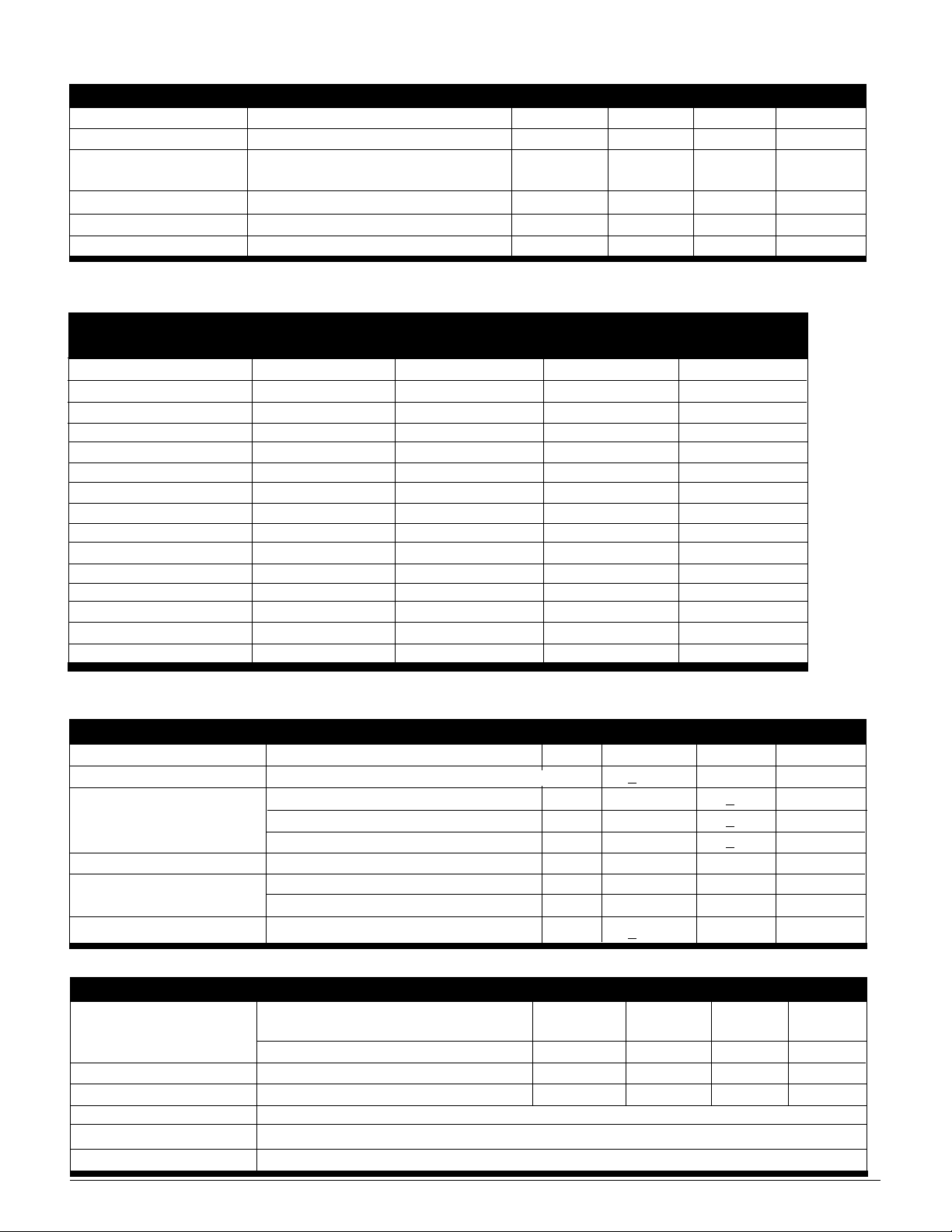
Input Specifications
Parameters Conditions Min Typ Max Units
Operating Range 47-63Hz 90 264 VAC
Input Current Nominal line, full load 8 A
Inrush Current 120V
240VAC, 250C, cold start 70 A pk
Efficiency Nominal line, full load 70 %
Holdup Full load 20 m
Pow er F actor
Notes: (1) Harmonic currents meet EN61000-3-2
(1)
Full load 0.99
0
AC, 25
C, cold start 30 Apk
Output Voltages and Maximum Rated Loads
OUTPUT #1 OUTPUT #2 OUTPUT #3 OUTPUT #4
MODEL NUMBER VOUT IMAX VNOM IMAX/IPK VNOM IMAX/IPK VNOM IMAX/IPK
PT500-U1A ± 3.3V 80A
PT500-U2A ± 3.3V 80A ± 12V 12A/15A
PT500-U2B ± 3.3V 80A ± 15V 12A/15A
PT500-U3A ±3.3V 80A ± 12V 12A/15A ± 12V 12A/15A - PT500-U3B ±3.3V 8 0A ± 15V 12A/15A ± 15V 12A/15A - PT500-U4C ±3.3 V 80A ± 5V 12A/15A ± 12V 12A/15A ± 12V 4.0A
PT500-U4D ±3.3 V 80A ± 5V 12A/15A ± 12V 12A/15A ± 24V 3.0A
PT500-U4E ±3.3V 80A ± 12V 12A/15A ± 12V 12A/15A ± 5V 4.0A
PT500-U4F ±3.3V 80A ± 5V 12A/15A ± 15V 12A/15A ± 15V 4.0A
PT500-U4G ±3.3V 80A ± 5V 12A/15A ± 15V 12A/15A ± 24V 3.0A
PT500-U4H ±3.3 V 80A ± 5V 12A/15A ± 12V 12A/15A ± 5.2V 10.0A
PT500-U4I ±3.3V 80A ± 5V 12A/15A ± 15V 12A/15A ± 12V 4.0A
PT500-U4J ±3.3V 80A ± 24V 4A ± 24V 4A ± 5V 10.0A
PT500-U4K ±3.3V 80A ± 5V 15A ± 12V 12A ± 5V 4.0A
PT500-U4L ±3.3V 80A ± 12V 12A ± 12V 12A ± 12V 4.0A
Note: Peak current ratings are for 10sec maximum. Total power not to exceed 500 watts.
sec
Output Specifications
Parameter Conditions Min Typ Max Units
Output Power All environmental and line conditions 500 Watts
Voltage Adjustment Range Relative to nominal output voltage, all outputs
Output Regulation Line
Load
Cross
Minimum Load Output #1 4 A
PARD V1, at output terminals, 20MHz B/W 50 mVp-p
Auxiliary Outputs 1 % pk-pk
Temperature Coefficient 0
0
to 500C, after 30 minute warm-up + 0.02 %/0C
+ 5 %
+ 0.1 %
+ 0.5 %
+ 0.1 %
Envir onmental Specifications
Parameter Conditions Min Typ Max Units
Ambient Temperature Operating output de-rated linearly to 50%
of rated capacity between 50
Non-operating -20 +85
Altitude Operating +10,000 Feet
Non-operating +50,000 Feet
Shock Per MIL-STD-810D, Method 516.3, Procedure I
Vibration Per MIL-STD-810D, Method 514.3, Procedure I
Cooling The PT500 is designed for full load operation in a 50°C ambient with 40 CFM airflow.
0
C and 700C 0 +70
0
C
0
C
PT500 4/99 REV APage 2

Product Features
Features Characteristic
Remote Sense 0.5V compensation, Output V1
Active Current Sharing Option Single Wire; 1% of max rated load
Cover w/Integral Fan Optional on all models
OVP 4.3V
Overcurrent Protection All outputs individually current limited with automatic recovery
Thermal Shutdown Automatic Restart
Power Fail Warning Signal (H) Transition to Logic “0” at least 10msec before loss of output regulation
Remote Inhibit (H) Logic “0” applied will inhibit output (referenced to –Sense terminal)
+0.5V, Output V1, latching
Product Compliances
Approval Characteristic
UL UL1950 and UL1012, File No. E14675
CSA C22.2 No. 234-M90, Level 6. File No. LR9070-154C
TUV EN60950, License No. R9576030
FCC, Part 15 Class B requirements for conducted emissions
VDE Class B requirements for conducted emissions
EN61000-3-2 Harmonic Currents, Class A
CE Mark Low Voltage Directive
Ordering Information
Model Designation
BASE MODEL
Chassis: “U” = unfinned, “M” = modified
Number of Outputs (1,2,3 or 4)
Output Voltage: See chart on facing page
Input Filter: “B” designates Class B EMI filter (standard feature)
Cover: “C” = plain cover, “F” = top mounted fan, “N” = no cover
Remote Inhibit: “H” designates that Logic “0” applied inhibits output (standard configuration)
Input: “P” designates Power Factor Corrected wide range (90-264V
Power Fail Warning: “H” designates transition to Logic “0” upon loss of AC (standard configuration)
Active Current Share: “M” designates current sharing on main output (V1) (standard feature)
NOTES: (1) Standard configurations shown; consult factory for other available options
(2) Cover required to meet EMI specification
(1)
PT500
(2)
AC) input (standard feature)
The information provided herein is believed to be reliable; however, C&D TECHNOLOGIES assumes no responsibility for inaccuracies or omissions. C&D TECHNOLOGIES
assumes no responsibility for the use of this information, and all use of such information shall be entirely at the user’s own risk. Prices and specifications are subject to
change without notice. No patent rights or licenses to any of the circuits described herein are implied or granted to any third party. C&D TECHNOLOGIES does not authorize
or warrant any C&D TECHNOLOGIES product for use in life support devices/systems or in aircraft control applications.
PT500 4/99 REV A Page 3

Mechanical
TOP VIEW
0.700
8.500
2.12
0.063
COVER
0.550
1
2
3
3.900
1
2
3
4.850
4
5
6
TB2
J9
3.3V
TB1
10.000
3.3V Return
Maximum depth of mounting screws is 0.156”
NOTES:
All dimensions are in inches
FAN MOUNTED ON CO VER ADDS 1.30”.
COOLING: The PT500 is designed to operate with 40 CFM airflow.
SHOCK AND VIBRATION: The PT500 family meets the requirements of MIL STD-810D. (Vibration-Method 514.3 Pocedure I; Shock-Method 516.3 Procedure I).
WEIGHT: Approximately 4 lbs.
Terminal Bloc k 1 Terminal Bloc k 2
POS FUNCTION POS FUNCTION
1 Ground 1 -V4
2 AC Neutral 2 +V4
3 AC Line 3 -V3
4 +V3
5 -V2
6 +V2
J9 Connector J9 Connector
PIN FUNCTION Molex No.
1 - Sense Connector 22-28-1050
2 + Sense
3 Current Share
4 Remote Inhibit
5 Power Fail
The information provided herein is believed to be reliable; however, C&D Technologies assumes no responsibility for inaccuracies or omissions. C&D Technologies assumes no
responsibility for the use of this information, and all use of such information shall be entirely at the user’s own risk. Prices and specifications are subject to change without notice. No patent
rights or licenses to any of the circuits described herein are implied or granted to any third party. C&D Technologies does not authorize or warrant any C&D Technologies product for use
in life support devices/systems or in aircraft control applications. C&D Technologies, Iso-ThermoFlex and T.E.A.M. Q are trademarks of C&D Technologies Corporation.
PT500 4/99 REV APage 4
 Loading...