

FEATURES
■ High Efficiency for Low Power
Applications
■ Pin Compatible with NME & NML
■ 1kVDC Isolation
■ SIP & DIP Package Styles
■ Single Output Rail
■ Power Density 0.36W/cm
3
■ 3.3V, 5V and 12V Input
■ 3.3V, 5V, 9V, 12V and 15V Output
■ Footprint from 0.69cm
2
■ UL 94V-0 Package Material
■ No Heatsink Required
■ Internal SMD Construction
■ Toroidal Magnetics
■ Fully Encapsulated
■ No External Components Required
■ MTTF up to 3.2 Million Hours
■ PCB Mounting
■ Custom Solutions Available
DESCRIPTION
The LME series of DC-DC converters are
optimised for low-power operation. Due to
the low quiescent current they are able to
offer efficiencies up to 75%. The use of
advanced magnetics ensures a minimal
quiescent current of around 2.5mA which
ensures that efficiency is maximised in low
power applications. They are ideally suited
to generating a negative supply where only
a positive rail exists.
LME SERIES
Isolated 250mW Single Output DC-DC Converters
SELECTION GUIDE
Nominal
Input Output Output Isolation Package
Voltage Voltage Current Efficiency Capacitance MTTF
Order Code (V) (V) (mA) (%) (pF) kHrs
LME0305D 3.3 5 50 70 25 2767 DIP
LME0305S 3.3 5 50 70 25 2767 SIP
LME0309D 3.3 9 28 75 30 1250 DIP
LME0309S 3.3 9 28 75 30 1250 SIP
LME0312D 3.3 12 21 75 38 655 DIP
LME0312S 3.3 12 21 75 38 655 SIP
LME0315D 3.3 15 16 75 38 367 DIP
LME0315S 3.3 15 16 75 38 367 SIP
LME0503D 5 3.3 76 70 25 2637 DIP
LME0503S 5 3.3 76 70 25 2637 SIP
LME0505D 5 5 50 70 29 2279 DIP
LME0505S 5 5 50 70 29 2279 SIP
LME0509D 5 9 28 75 37 1139 DIP
LME0509S 5 9 28 75 37 1139 SIP
LME0512D 5 12 21 75 41 624 DIP
LME0512S 5 12 21 75 41 624 SIP
LME0515D 5 15 16 75 40 357 DIP
LME0515S 5 15 16 75 40 357 SIP
LME1205D 12 5 50 70 38 536 DIP
LME1205S 12 5 50 70 38 536 SIP
LME1209D 12 9 28 75 40 434 DIP
LME1209S 12 9 28 75 40 434 SIP
LME1212D 12 12 21 75 43 330 DIP
LME1212S 12 12 21 75 43 330 SIP
LME1215D 12 15 16 75 45 237 DIP
LME1215S 12 15 16 75 45 237 SIP
When operated with additional external load capacitance the rise time of the input voltage will determine the
maximum external capacitance value for guaranteed start up. The slower the rise time of the input voltage the
greater the maximum value of the additional external capacitance for reliable start up.
INPUT CHARACTERISTICS
Parameter Conditions MIN TYP MAX Units
Continuous operation, 3.3V input types 2.97 3.3 3.63
Voltage Range Continuous operation, 5V input types 4.5 5 5.5 V
Continuous operation, 12V input types 10.8 12 13.2
OUTPUT CHARACTERISTICS
Parameter Conditions MIN TYP MAX Units
Rated Power2TA= 0°C to 70°C 0.25 W
Voltage Set
Point Accuracy
Line Regulation High VINto low V
Load Regulation
Ripple & Noise
See tolerance envelope
IN
10% load to rated load,
3.3V & 5V output types
10% load to rated load,
all other output types
BW=DC to 20MHz, LME03 types 75
BW=DC to 20MHz, all other output types 100
1
Style
1.2 %/%
15
%
10
mV p-p
www.dc-dc.com
ABSOLUTE MAXIMUM RATINGS
Short-circuit duration
Lead temperature 1.5mm from case for 10 seconds 300°C
Input voltage VIN, LME03 types 5V
Input voltage VIN, LME05 types 7V
Input voltage VIN, LME12 types 15V
1 Calculated using MIL-HDBK-217F with nominal input voltage at full load.
2 See derating curve
3 Supply voltage must be discontinued at the end of the short circuit duration.
All specifications typical at TA=25°C, nominal input voltage and rated output current unless otherwise specified.
3
1 second
LME SERIES
Isolated 250mW Single Output DC-DC Converters
ISOLATION CHARACTERISTICS
Parameter Conditions MIN TYP MAX Units
Isolation Test Voltage Flash tested for 1 second 1000 VDC
Resistance Viso=500VDC 1 GΩ
GENERAL CHARACTERISTICS
Parameter Conditions MIN TYP MAX Units
Switching Frequency All input types 100 kHz
TEMPERATURE CHARACTERISTICS
Parameter Conditions MIN TYP MAX Units
Specification All output types 0 70 °C
Storage –55 150 °C
Cooling Free air convection
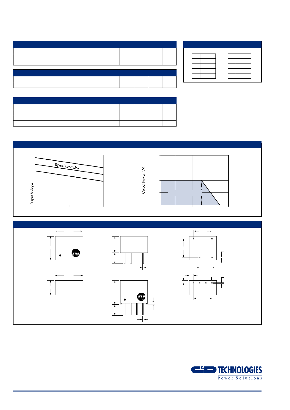
PERFORMANCE CHARACTERISTICS
+10%
+5%
V nominal
tolerance envelope
+2.5%
-2.5%
-7.5%
temperature derating graph
0.500
0.375
0.250
PIN CONNECTIONS
8 Pin DIP
PIN
1 GND
4 V
IN
5 +V
7 0V
4 Pin SIP
PIN
1 GND
2 V
3 0V
4 +V
IN
10 50 100
Output Load Current (%)
MECHANICAL DIMENSIONS
8 Pin DIP
11.50
LME0505D
YYWW
9.80
4 Pin SIP
6.00
11.50
6.80
4.1
10.0
4.1
LME0505S
YYWW
1
2 3 4
0.125
Safe Operating Area
0
–40 0 50 70 100 125 150
Ambient Temperature (°C)
7.62
1
7.62
7 5
1.9 Printed Face
1.25
7.62
0.50±0.05
0.50±0.05
All dimensions in mm XX.XX ±0.25mm. All pins on a
2.54mm pitch and within ±0.25mm of true position.
4
0.25±0.05
5.080.50±0.05
0.25±0.05
C&D Technologies (NCL) Limited reserve the right to alter or improve the
specification, internal design or manufacturing process at any time, without
notice. Please check with your supplier or visit our web site to ensure that
you have the current and complete specification for your product before use.
© C&D Technologies (NCL) Limited 2001 NDC LME.2
No part of this publication may be copied, transmitted or stored in a
retrieval system or reproduced in any way including, but not limited to,
photography, photocopy, magnetic or other recording means, without prior
written permission from C&D Technologies (NCL) Limited.
Instructions for use are available from www.dc-dc.com
C&D Technologies (NCL) Ltd
Tanners Drive, Blakelands North
Milton Keynes MK14 5BU, England
Tel: +44 (0)1908 615232
Fax:+44 (0)1908 617545
email: info@cdtechno-ncl.com
www: http://www.dc-dc.com
C&D Technologies (NCL), Inc.
5816 Creedmoor Road, Raleigh
NC 27612, USA
Tel: +1 (919) 571-9405
Fax: +1 (919) 571-9262
email: info@us.cdtechno-ncl.com
 Loading...