

Page 1
K
(
)
VRLA
41-6976
VRLA RB BATTERY RACKS
ASSEMBLY INSTRUCTIONS
(READ ALL INSTRUCTIONS PRIOR TO INSTALLATION)
For All Standard And Seismic Models Including Retrofitting
Standard Models To Meet Seismic Requirements
Safety
Installation of VRLA batteries should only be performed and supervised by trained personnel knowledgeable of lead
acid batteries and the required personal and equipment safety precautions. Keep unauthorized personnel away from
the batteries and assembly activity.
Observe battery safety procedures. Use insulated tools, gloves, safety glasses, and remove all jewelry etc..
Special care should always be taken to avoid short circuiting any battery connection.
Wash hands after any contact with lead or electrolyte.
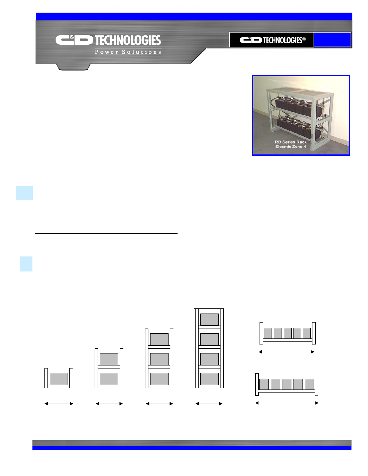
Rack Configurations
Racks are available in single or multiple tiers. Rack components must be assembled and secured on-site in
accordance with these C&D assembly instructions, rack drawings and applicable codes. Because EQ Racks meet
Seismic requirements, they may NOT be mechanically secured together.
A minimum distance of 3” must be allowed between racks and between racks and the building structure.
Rack Height
Rack Height
38.25"
Rack Height
21.25"
1 Tier 2 Tier 3 Tier
Depth
18.5"
Depth
18.5"
55.38"
Depth
18.5"
Rack Height
72.5"
4 Tier
w/Cover
Depth
18.5"
Narrow Rack
Width 38.0"
Wide Rack
Width 44.0"
End View Front View
Page 2

#
Ã
a
VRLA
Page 2 of 9
Tools for RB Rack Assembly
The following items will assist you to properly assemble rack materials. Insulated tools are strongly recommended
for safety purposes.
9/16” socket wrench Torque wrench to 46ft-lbs Tape measure
9/16” open-end wrench Needle nose pliers Knife
Chalk and line to mark floor Bubble level Square
Power drop cord Drill & concrete bit (for floor anchors)
Required Materials Supplied by Installer
Seismic Qualified floor anchor bolts (4 per rack)
1/8” thick (X) 2 3/8” wide (X) 3 3/8” long metal shims with 15/16” centered cutout (length wise).
Quantity of shims depends on floor surface.
Rack Location
Locate racks in a clean, cool, dry environment to avoid exposing the batteries to sources of radiant heat, such as
sunshine, heating units, radiators, and steam pipes etc. Top rows of batteries in multiple-tier configurations tend to
operate at a slightly higher temperature than batteries on lower tiers. Always provide adequate ceiling clearance for
ventilation and maintenance.
Í
☯
Anchoring
Seismic racks must be securely anchored to the floor and in accordance with applicable codes and regulations. Four
15/16” diameter mounting holes are provided in the rack base. Seismic racks must be secured to the floor using ALL
anchor bolt locations.
Anchor mounting hardware must be capable of withstanding foundation allowable loads of 4,000-lbs. pullout and 576lbs. shear. Anchor spacing based upon the mounting holes in the RB Rack is 12.5”. You must allow a minimum of 3”
between racks and between racks and the building structure to allow for drift.
To properly select anchoring system hardware, the concrete floor strength in psi must be
determined.
Grounding
Each rack has grounding strap provisions. Two 15/32” diameter mounting holes are located on each vertical frame
and accept single hole or dual hole lugs on 1” centers. The surfaces surrounding the holes are free of powder coat to
allow electrical contact.
Standard and Seismic Rack Comparison
EQ series Seismic Zone 4 racks are similar to standard racks, but with the addition of hold down struts, battery end
brackets, spacers, and covers for Seismic racks. Frames are the same for both Standard and EQ series racks. EQ
series Seismic racks are certified to the 1997 Uniform Building Code.
Page 3
VRLA
Page 3 of 9
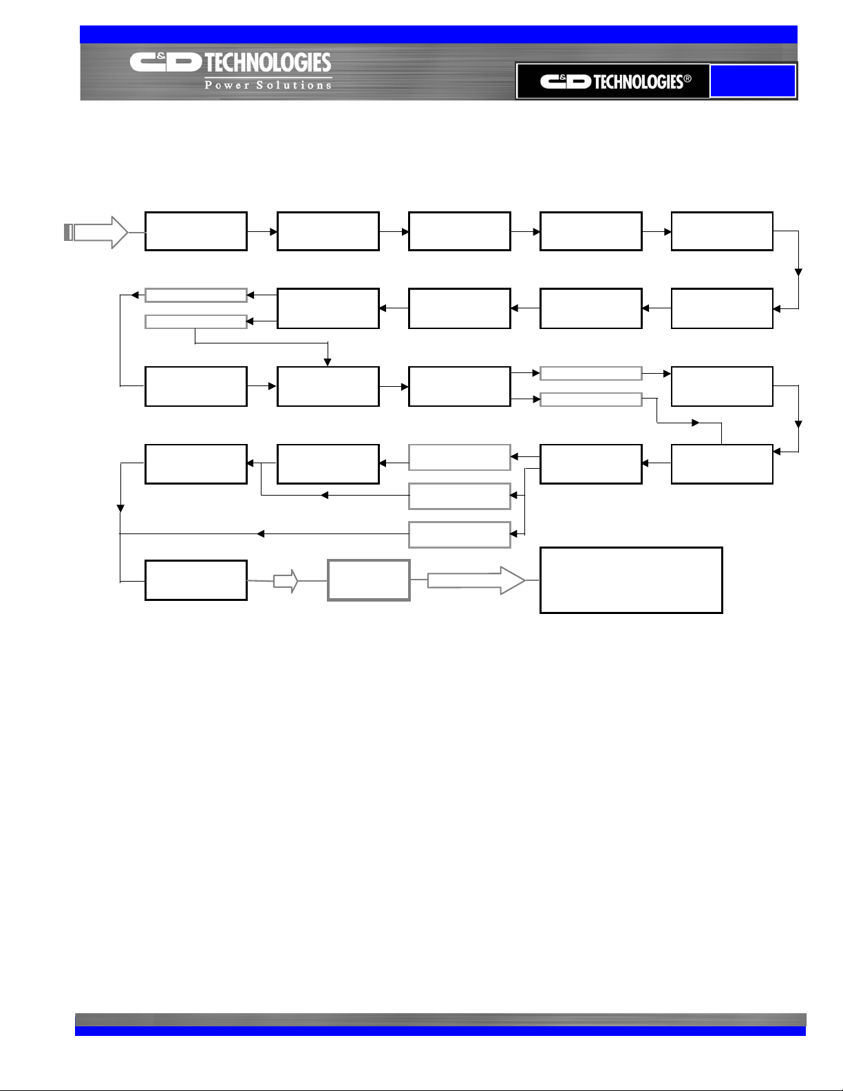
VRLA RB Battery Rack Assembly - Task Flow Chart
START
Receive and inspect
Rack Components
Seismic Rack
Standard Rack
Install hold down rod
Install Top Cover
Verify proper torque
of all connecting
hardware
Review drawings &
instructions
Assemble rack tiers
(rails), level rack and
torque bolts
Prepare Batteries for
Installation
Install Seismic Hold
Down Kit
To cable
installation phase
Verify parts received
against Bill of
Materials
Mount sway braces to
support frame
Install Batteries
Seismic Rack
Standard Rack with
cover
Standard Rack
without cover
QUESTIONS ?
Obtain installer
supplies - Anchor
bolts & shims etc.
Secure end support
frames to floor
Seismic Rack
Standard Rack
Install ground strap to
rack
Contact C&D Technologies @
1-800-543-8630
Get safety equipment
and tools to rack
location
Install floor mounting
hardware
Install spacer blocks
and end braces
Affix identification
labels to batteries and
strings
1. Receive and inspect rack components
Upon receipt of the RB Rack materials, inspect and document any damage to these materials.
Damage claims must be filed promptly with the carrier.
2. Review drawings and instructions
3. Verify Parts Received Against Bill of Materials
Standard RB Series Rack components are shipped in 2 boxes. If an optional cover was ordered, there will be one
additional box.
Seismic RB Series Racks are shipped in 3 boxes plus one additional box for each tier.
Before assembly, verify that all rack materials are present against the detailed bill of materials shown on the RB
Rack Assembly Drawing (RB_ _T) or (RB_ _TEQ).
4. Obtain installer supplies (listed on page 2)
5. Get safety equipment and tools (listed on page 2) to rack installation location
Page 4

A
p
VRLA
Page 4 of 9
6. Install floor-mounting hardware (supplied by installer)
Locate the rack’s general position, considering boundary and aisle clearances.
Locate floor-mounting locations.
Mark the floor for drilling floor anchor holes using dimensions shown below.
Ref. Dim.
Narrow Rack A 36.0”
Narrow Rack B 12.5”
Both Racks C 15/16” diam.
Wide Rack A 42.0”
C
(Diam.)
Floor Mtg. Holes
End Support
Frames
(Insides facing)
Wide Rack B 12.5”
7. Secure end-support frames to floor finger tight.
Depending on the installation method, sway braces can be installed per step 8 before securing end support frames
to the floor.
8. Install 2 sway braces to 2 end support frames and braces to themselves at their centers
Mounting hardware starting at outer rack surface – finger tight
1.25” (x) 3/8” – 16 Hex Bolt
3/8” Flat Washer
(materials being joined together)
3/8” Flat Washer
Mounting
Hardware
Locations
Sway Brace
End
Support
Frame
3/8” Star Washer
3/8” – 16 Hex nut
Rear View
9. Assemble rack tiers (LOWEST first), level rack and torque bolts
Adjust distance between rails to accommodate length of batteries to be installed.
Do NOT install batteries at this time.
After assembling:
a) Place one KYDEX insulating strip onto each battery support angle
b) Level and square all rack materials installed to this point using installer supplied shims
c) Torque all mounting hardware to 46 ft lbs. Torque floor anchors per manufacturer’s specification.
Mounting hardware starting at top of rack surface – finger tight
1.0” (x) 3/8” – 16 Hex Bolt
3/8” Flat Washer
(materials being joined together)
3/8” Flat Washer
Mounting
Hardware
3/8” Star Washer
3/8” – 16 Hex nut
End
Support
Frame
View
To
Rails
B
Page 5

VRLA
10. Seismic Racks – Install hold down rod on each tier’s end support frame
Mounting hardware starting at top of end-frame surface
Torque to 46 ft lbs
13 ¾” long Threaded rod 3/8” – 16 (End support frame)
3/8” Hex nut 3/8” Flat washer
3/8” Flat washer 3/8” – 16 Hex nut
Threaded
Rod
Mounting
Hardware
(Inside View)
End Support
Frame
11. Prepare Battery Terminals
Remove any pre-existing grease then lightly brush terminal contact surfaces with a brass brush or Scotch Brite
type pad. Coat terminals with anti-oxidant NO-OX-ID type grease or equivalent.
12. Install Batteries
Center KYDEX insulators on each battery support angle. Starting at the center of the LOWEST tier, install
batteries working out to each end. Leave a MIMIMUM of 0.5” between batteries for required ventilation. Pay
particular attention that each tier of batteries is oriented the same direction.
13. Seismic Racks – Install spacer blocks and secure end braces to battery support rail
End Brace
Mounting Hardware – torque to 46 ft lbs
3/8” – 16 Hex bolt 3/8” Flat washer
3/8” Flat washer 3/8” Star washer
Bracing Bracket 3/8” Hex nut
Support Rail
End Brace
with mounting
hardware
Support Rail Assembly with Batteries, Spacers, and End Braces
End brace mounting holes in battery support rail
Battery
Spacer
Block
Spacer block between end
brace and battery not
required when holes in end
brace match up to holes in
support
rail.
14. Affix identification labels to batteries and racks
Refer to the system wiring schematic.
The battery having the positive output for the string should be labeled as #1. Continue labeling the remaining
batteries in this string in ascending sequential order as they are connected in series from the #1 battery. The
battery at the negative output for this string will be the highest numbered battery.
Battery numbering sets are available through your C&D Dynasty Distributor. Individual strings that are connected
in parallel should be uniquely identified as “A”, “B” and “C”.
15. Install Ground Strap (supplied by installer) to Rack
Each vertical member of the end-support frame has 2 each 15/32” holes on 1.0” centers. They accommodate a
single hole or a 2-hole lug. The National Electrical Code 150-166 specifies conductor size will not be smaller than
the largest system conductor and in any case not smaller than #8 copper (#6 aluminum). The end of the ground
strap not attached to the rack should be connected in accordance with applicable codes.
Page 5 of 9
Page 6

Seismic Rack – Install Hold Down Kit
16.
CAUTION – Avoid shorting battery terminals against hold down strut!!
Place a KYDEX insulator over a hold down strut.
Hold down strut and
KYDEX insulator
Threaded rod, wing
nut and square
washer
Mounting Hardware
• Square washer
Battery
• 3/8” – 16 Wing nut
End support frame
Seismic Hold Down Kit - Front View RB Rack
Turn these parts over to form a “U” – Place the hold down assembly over the two threaded rods and connect the
hardware – ¼ turn past finger tight.
Install Top Cover (Seismic and Standard Rack as option)
17.
Mounting Hardware starting at outer cover
surface– torque to 46 ft lbs
Cover - Top View
Cover - Side View
• ¾” L Carriage bolt #3/8 – 16
(Top cover)
• 3/8 Flat washer
• 3/8 Lock washer
• 3/8 – 16 Hex nut
RB Rack - Front View
Verify proper torque of all connecting hardware
18.
Retrofitting Standard RB Racks
To Seismic Zone 4 Requirements
RB Rack Retrofit Materials Required
To retrofit an installed standard RB Rack to seismic Zone 4 standards, the C&D Dynasty retrofit options listed below
are required. For each part ordered, you will receive one box marked with the indicated part number shown. If a
quantity of 4 items is ordered, you will receive 4 separate boxes.
Part Description Quantity Required Part No. – Narrow Rack Part No. – Wide Rack
Top Cover 1 SMF101N SMF101W
Seismic Hold Down Kit 1 for each tier SMF105N SMF105W
VRLA
Page 6 of 9
Rail
Page 7

VRLA
Page 7 of 9
VRLA RB Battery Rack Retrofit - Task Flow Chart
START
Receive and inspect
retrofit components
Verify proper torque
of all connecting
hardware
Review drawings &
instructions
Install hold down rodInstall top cover
QUESTIONS ?
Verify retrofit items
received against Bill
of Materials
Install hold down strut
and KYDEX insulator
Contact C&D Technologies @
1-800-543-8630
Get safety equipment
and tools to rack
location
Install spacer blocks
and end braces
Verify rack is properly
anchored
Check installed
cables for adequate
clearance
R-1. Receive and inspect rack components
Upon receipt of the RB Rack materials, inspect and document any damage to these materials. Damage
claims must be filed promptly with the carrier.
R-2. Review drawings and instructions
R-3. Verify Parts Received Against Bill of Materials
Before assembly, verify that all rack materials are present against the detailed bill of materials shown on the RB
Rack Assembly Drawing (RB_ _TEQ).
R-4. Get safety equipment and tools to rack installation location
Safety equipment
as described on page 1 of this publication.
Tools
- The following items will assist you to properly install RB Rack retrofit materials.
Insulated tools are strongly recommended for safety purposes.
9/16” Socket wrench Torque wrench to 46ft-lbs Tape measure
9/16” Open-end wrench Needle nose pliers Knife
R-5. Anchoring
It is very important that the rack is securely anchored to the floor using ALL
holes provided in the rack’s base.
It is the responsibility of the installer to verify that the rack is anchored in accordance with allowable floor
loading, applicable codes and regulations. Under normal conditions, this should have been done with the initial
installation of the rack. If not, it needs to be done prior to performing the following procedures.
four 15/16” diameter mounting
Page 8

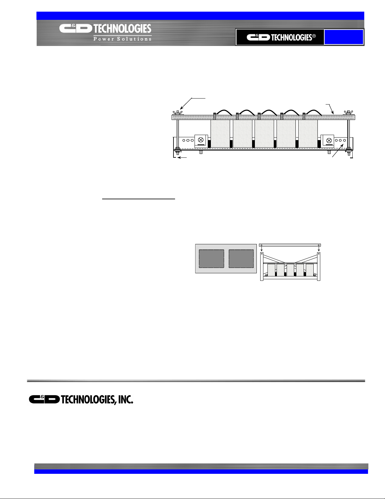
R-6. Check installed cables for adequate clearance
One inch clearance is required between the underside
of inter-connecting cables and the top of all battery
cases across each tier to accommodate the P3300 hold down strut and KYDEX insulating channel.
If this space is not available due to insufficient cable lengths, new cables of the correct length must be installed.
This situation will require replacing existing cables before going to the next assembly operation.
R-7. Seismic Racks – Install spacer blocks and secure end braces to battery support rail
End Brace
Mounting Hardware – torque to 46 ft lbs
3/8” – 16 Hex bolt 3/8” Flat washer
3/8” Flat washer 3/8” Star washer
Bracing Bracket 3/8” Hex nut
Support Rail
End Brace
with mounting
hardware
Support Rail Assembly with Batteries, Spacers, and End Braces
End brace mounting holes in battery support rail
Battery
Spacer
Block
Spacer block between end
brace and battery not
required when holes in end
brace match up to holes in
support
rail.
R-8. Install Seismic hold down strut and KYDEX insulator
CAUTION – Avoid shorting battery terminals against hold down strut !!
Place the “U” shaped KYDEX insulating
channel over the “U” shaped Hold down
strut.
Position this assembly so it looks like a
“U”. The KYDEX insulator will now be on
the bottom.
Starting on the lowest tier, at either end of
the rack, slide the hold down strut/insulator
assembly under the inter-cell cables so
that the flat side of the strut assembly rests
CENTERED on top of the battery cases.
Repeat this step for each tier.
Hold down strut assembly Cable
Battery
End Brace
Spacer block Battery Support Rail
VRLA
Page 8 of 9
Page 9
R-9. Install hold down rod
Attach a rod to each end support frame starting with the lowest tier Mounting Hardware – torque to 46 ft lbs
13 ¾” long threaded rod 3/8” – 16
3.8” hex nut
3/8” flat washer
end support frame
3/8” flat washer
3/8” – 16 hex nut
End Support Frame
Then secure the rod to the hold down strut
Mounting hardware – ¼ turn past finger tight
Square washer
3/8” wing nut – DO NOT OVER TORQUE
wing nut
R-10. Install Top Cover
Mounting Hardware starting at outer cover surface– torque to 46 ft lbs
• ¾” L Carriage bolt #3/8 – 16
(Top cover)
• 3/8 Flat washer
• 3/8 Lock washer
• 3/8 – 16 Hex nut
R-11. Verify proper torque of all hardware
REMEMBER, the wing nut on top of the hold down strut is only tightened ¼ turn past finger tight.
Hold down rod with square washer & wing nut
Cover - Top View
Hold down strut assembly
Battery
Battery Support Rail
Cover - Side View
RB Rack - Front View
VRLA
Page 9 of 9
Any data, descriptions or specifications presented herein are subject to revision by C&D
Technologies, Inc. without notice. While such information is believed to be accurate as indicated
herein, C&D Technologies, Inc. makes no warranty and hereby disclaims all warranties, express
1400 Union Meeting Road
P.O. Box 3053 • Blue Bell, PA 19422-0858
(215) 619-2700 • Fax (215) 619-7899 • (800) 543-8630
customersvc@cdtechno.com
www.cdtechno.com
or implied, with regard to the accuracy or completeness of such information. Further, because
the product(s) featured herein may be used under conditions beyond its control, C&D
Technologies, Inc. hereby disclaims all warranties, either express or implied, concerning the
fitness or suitability of such product(s) for any particular use or in any specif ic application or
arising from any course of dealing or usage of trade. The user is solely responsible for
determining the suitability of the product(s) featured herein for user’s intended purpose and in
user’s specific application.
Copyright 2007 C&D TECHNOLOGIES, INC. Printed in U.S.A. 41-6976
 Loading...