


cdtechno NPH10S2403i, NPH10S2412Ei, NPH10S2405i, NPH10S2415i, NPH10S4805Ei Datasheet
...
NPH10S SERIES
Isolated 10W Single Output DC-DC Converters
www.cdpoweronline.com
SELECTION GUIDE
FEATURES
■ High Efficiency to 86%
■ Power Density up to 1.5kW/L
(24W/in
3
)
■ 1.5kV Input to Output Isolation
■ Industry Standard Pinout
■ Surge Rating to 12W
■ Non Latching Current Limit
■ Fixed Frequency
■ Versatile Control Options
■ Continuous Rating to 10W at 72°C
Without Heatsink
■ Operation to Zero Load
■ Protected Against Load Faults
■ Internal Over Temperature Protection
■ Uses No Electrolytic Capacitors
■ UL 94V-0 Package Materials
DESCRIPTION
The NPH10S series of DC-DC Converters
combines ease of application with versatility.
The pin pattern is based on the popular
industry standard, but two additional pins
may optionally be fitted to provide a variety
of features not commonly found on units of
this type. High efficiency enables full rating
to be achieved in a small package without
heatsinking. Thermally protected against
sustained overload. The copper case
achieves efficient heat transfer and screening.
The product range has been recognised by
Underwriters Laboratory (UL) to UL 1950 for
operational insulation, file number E179522
applies.
Nominal Output Output Current Max Load
Input Voltage Voltage Current Limit2(Typ) Efficiency
Capacitance
Order Code
1
(V) (V) (A) (A) (%) (µF)
NPH10S2403i
24 3.4 2.94 4.5 79 470
NPH10S2405i
24 5.1 1.96 3.0 83 470
NPH10S2412i
24 12.1 0.83 1.2 86 100
NPH10S2415i
24 15.1 0.67 1.1 86 47
NPH10S4803i
48 3.4 2.94 4.1 80 470
NPH10S4805i
48 5.1 1.96 2.8 83 470
NPH10S4812i
48 12.1 0.83 1.2 86 56
NPH10S4815i
48 15.1 0.67 1.0 87 22
Parameter Conditions MIN NOM MAX Units
Voltage Range
Continuous operation, 24V input types 18 24 36 V
Continuous operation, 48V input types
3
36 48 75 V
Parameter Conditions MIN TYP MAX Units
Voltage Set 50% load after 30 mins at nominal
0.5 %
Point Error supply voltage
Overall
Case temperature –40°C to 110°C
Voltage Error
Load 0% - 100% 1 2.5 %
Input specified range
Temperature Coefficient
Over any 10°C span within the
of Output Voltage
specified temperature range
50 250 ppm°C
(slope)
Deviation of
Output Voltage
Specified over temperature MIN-MAX
0.5 1 %
Line Regulation Operating voltage range, 50% load 0.05 0.1 %
Load Regulation 0% - 100% rated load
4
0.5 %
Ripple rms 70 mV
Input voltage, 24V input types –0.5V to 40V
6
Input voltage, 48V input types –0.5V to 80V
6
Output Voltage
–0.3V to controlled output voltage (operating or non-operating)
Output trim control –1V to +30V
Synchronisation/shutdown control ±15V relative to input return
INPUT CHARACTERISTICS
OUTPUT CHARACTERISTICS
Parameter Conditions MIN TYP MAX Units
Voltage Trimming At rated load,
±10 %
Range Trim control at either output
Remote Switch Input
5
Not operating -15 0 1.5
V(voltage relative
to input negative)
Operating, open circuit voltage 9 10 11
Start Delay
Time from application of valid input
voltage to output being in specification
25 mS
Synchronisation
5
Specified drive signal 320 440 kHz
Switching Frequency 330 350 395 kHz
CONTROL CHARACTERISTICS
ABSOLUTE MAXIMUM RATINGS
ISOLATION CHARACTERISTICS
Parameter Conditions MIN TYP MAX Units
Isolation Voltage Flash tested for 1 second 1500 VDC
Resistance Viso=500VDC 1 GΩ
Capacitance
3.3V and 5V output 50
pF
12V and 15V output 90
1 If optional pins ADJ and SS are required (as indicated in the pin connections diagram) prefix the ending “i” with
an E when ordering, e.g. NPH10S4803Ei.
2Current is quoted when output is 95% of regulated voltage.
3 For applications requiring UL1950 recognition, input voltage must not exceed 60VDC.
4A minimum load of 10% of rating is recommended for typical applications ; see application notes.
5 Optional - Where fitted.
6 Absolute maximum value for 30 seconds. Prolonged operation may damage the product.
All specifications typical at TA=25°C, nominal input voltage and rated output current unless otherwise specified.
NPH10S SERIES
Isolated 10W Single Output DC-DC Converters
C&D Technologies (NCL) Ltd
Tanners Drive, Blakelands North
Milton Keynes MK14 5BU, England
Tel: +44 (0)1908 615232
Fax:+44 (0)1908 617545
email: info@cdtechno-ncl.com
www.cdpoweronline.com
C&D Technologies Inc.
3400 E Britannia Drive, Tucson,
Arizona 85706, USA
Tel: +1 (800) 547-2537
Fax: +1 (520) 741-4598
email: sales@cdtechno.com
C&D Technologies (NCL) Limited reserve the right to alter or improve the
specification, internal design or manufacturing process at any time, without
notice. Please check with your supplier or visit our web site to ensure that
you have the current and complete specification for your product before use.
For information and instructions on use, please consult the NPH SERIES
APPLICATION NOTES.
© C&D Technologies (NCL) Limited 2003 NDC NPH10S.6
No part of this publication may be copied, transmitted or stored in a
retrieval system or reproduced in any way including, but not limited to,
photography, photocopy, magnetic or other recording means, without prior
written permission from C&D Technologies (NCL) Limited.
Instructions for use are available from www.cdpoweronline.com
ENVIRONMENTAL
Parameter Conditions MIN TYP MAX Units
Case Temperature Full load –40 110 °C
Storage Absolute MAX internal temperature –40 125 °C
Relative Humidity Non condensing 85°C 85 %
Thermal Protection Operates at case temperature 110 °C
Weight: 22g
All dimensions in Inches (mm) ± 0.01 (0.25)
All pins on a 0.10 (2.54) pitch and within ± 0.01 (0.25) of true position
* Optional pins
Case connected internally to 0V pin
0.8
20.32
0.98
25.00
0.80 (20.32)
0.39 (10.00)
1.78 (4.50)
0.15 (3.70)
0.39 (9.96)
0.23
(5.84)
0.2 (5.08)
THERMAL CHARACTERISTICS
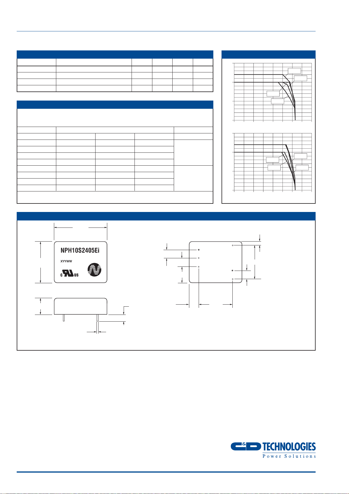
THERMAL PERFORMANCE
MAX power rating with case temperature maintained by external means
(eg forced air cooling)
Case Temperature
Part Number 100°C 105°C 110°C Units
NPH10S2403
10 7.0 2.3
NPH10S2405
10 8.2 3
NPH10S2412
10 9.5 4
W
NPH10S2415
12 9.5 4
NPH10S4803
10 7.0 1
NPH10S4805
10 4.7 1
NPH10S4812
12 8.0 0
W
NPH10S4815
12 7.5 0
MECHANICAL DIMENSIONS
15
10
5
0
-40 -20 0 20 40 60 80 100 120
Ambient Temperature (°C)
2412
2415
2405
2403
Output Power (W)
15
10
5
0
-40 -20 0 20 40 60 80 100 120
Ambient Temperature (°C)
Output Power (W)
4815
4812
4805
4803
SS
+V
IN
-V
IN
+V
OUT
ADJ
0V
0.2 (5.08)
BOTTOM VIEW
0.09 (2.34)
0.2 (5. 08)
Ø
0.04 (1.04)
0.04 (0.90)
1.26
(32.00)